1
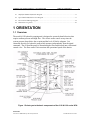
Installation and Operations Manual — Model 611X HPU Series MODEL 611x SERIES Wedges & Bollards Hydraulic Pumping Unit (HPU) OPERATIONS & MAINTENANCE MANUAL B&B ARMR CORPORATE OFFICE & TECHNICAL SUPPORT: 2009 CHENAULT DRIVE SUITE 114 CARROLLTON, TX 75006 PHONE: 800-367-0387 FAX: (972) 385-9887 E-mail: [email protected] [email protected] MADE IN THE USA B&B ARMR A Division of B&B Roadway and Security Solutions 611XWB-9001 Revision B2 Installation and Operations Manual — 611x Series HPU INTRODUCTION Your safety is extremely important to us. If you have any questions or are in doubt about any aspect of the equipment, please contact us. INTRODUCTION Welcome! Congratulations on your purchase of a B&B ARMR Hydraulic Pumping Unit (HPU). In addition to providing detailed operating instructions, this manual describes how to install, maintain, and troubleshoot your HPU. If you require additional assistance with any aspect of your installation or operation, please contact us. We have years of experience in all aspects of perimeter security and related disciplines, and our products are used throughout the world to control access and to protect people, equipment, and facilities. We offer a broad range of vehicle barrier and related security services: Turnkey installations Routine barrier preventative maintenance or emergency repairs (including work on non-B&B ARMR products) Spare or replacement parts Custom designs or special installations Equipment upgrades (modernize your old equipment with state-of-the-art hydraulics and control systems) Ancillary security equipment such as security guard enclosures, card readers, security lighting, and many other security related products. Technical support via telephone and possible on site support with advanced scheduling. Safety B&B ARMR A Division of B&B Roadway and Security Solutions 611XWB-9001 Revision B2 ii Installation and Operations Manual — 611x Series HPU INTRODUCTION SYMBOL MEANING: The lightning flash with arrowhead symbol, within an equilateral triangle, is intended to alert the user to the presence of non-insulated "dangerous voltage" within the product's enclosure that may be of sufficient magnitude to constitute a risk of electric shock to persons. The exclamation point within an equilateral triangle is intended to alert the user to the presence of important operating and maintenance (servicing) instruction in the literature accompanying the product. B&B ARMR does not assume responsibility for injury to persons or property during installation, operation, or maintenance. As the user, you are responsible for correct and safe installation, operation, and maintenance of this equipment. Users must follow the specific instructions and safety precautions located in this manual. In addition they must: Follow the safety standards of the Occupational Safety and Health Administration (OSHA), as well as other applicable federal, state, and local safety regulations and industry standards and procedures. For installation outside the United States, users must also follow applicable international, regional, and local safety standards. Engage only trained and experienced staff to install, operate, and maintain the equipment. Ensure that all repairs are performed correctly, using properly trained technicians and the correct tools and equipment. This HPU comes with a power ON/OFF switch. Although this switch does cut the power to the motor and various other devices, always use correct lock-out and safety procedures when servicing the unit. This unit is designed to be operated with the covers in place. Extreme caution should be used when operating without covers. Additional system safety devices may be included with this barrier system: o Vehicle loop detector(s) – Safety loop o Traffic arms o Traffic lights o IR beams o Safety edges B&B ARMR A Division of B&B Roadway and Security Solutions 611XWB-9001 Revision B2 iii Installation and Operations Manual — 611x Series HPU INTRODUCTION How to Contact Us If you have any questions or experience any problems with your vehicle barrier—or if we can help you with any other facility security issues—please contact us directly at: Corporate/Tech Support: B&B ARMR 2009 Chenault Drive Suite 114 Carrollton, TX 75006 USA Telephone: (972) 385-7899 Toll Free: (800) 367-0387 Fax: (972) 385-9887 E-mail: [email protected] [email protected] B&B ARMR A Division of B&B Roadway and Security Solutions 611XWB-9001 Revision B2 iv Installation and Operations Manual — 611X Series HPU TABLE OF CONTENTS Table of Contents INTRODUCTION........................................................................................................ii Safety ..............................................................................................................................ii How to Contact Us ....................................................................................................... iv 1 ORIENTATION ................................................................................................... 6 1.1 Overview .......................................................................................................................................... 6 1.1.1 Electrical Control Box ............................................................................................................ 7 1.1.2 Flow Control Valve ................................................................................................................ 7 1.1.3 System relief Valve ................................................................................................................ 7 1.1.4 Tank Weldment ...................................................................................................................... 7 1.1.5 Oil Site Gauge ........................................................................................................................ 7 1.1.6 Manifold Block ....................................................................................................................... 7 1.1.7 Pressure Switch....................................................................................................................... 8 1.1.8 Hand Pump ............................................................................................................................. 8 1.1.9 Pressure gauge ........................................................................................................................ 8 1.1.10 Accumulator....................................................................................................................... 8 1.1.11 Pump .................................................................................................................................. 8 1.1.12 Electric Motor .................................................................................................................... 8 1.1.13 EFO Valve and Coil ........................................................................................................... 8 1.1.14 Base Filter Assembly ......................................................................................................... 8 1.1.15 Directional Control Valve .................................................................................................. 9 1.1.16 Cabinet ............................................................................................................................... 9 1.1.17 Options ............................................................................................................................... 9 2 3 4 OPERATION ........................................................................................................ 9 2.1 Introduction ...................................................................................................................................... 9 2.2 Control Signals ................................................................................................................................ 9 2.3 Emergency Fast Operation (EFO) ................................................................................................... 9 2.4 Manual Operation ...........................................................................................................................10 MAINTENANCE ................................................................................................11 3.1 Introduction .....................................................................................................................................12 3.2 Monthly Inspections ........................................................................................................................12 3.3 Six-Month Inspections .....................................................................................................................13 3.4 Annual Maintenance Inspections ....................................................................................................13 TROUBLESHOOTING ..................................................................................... 14 4.1 611x Series HPU Troubleshooting Guide .......................................................................................14 5 WARRANTY ........................................................................................................ 16 6 APPENDIX.......................................................................................................... 17 B&B ARMR A Division of B&B Roadway and Security Solutions 611XWB-9001 Revision B2 5 Installation and Operations Manual — 611X Series HPU TABLE OF CONTENTS 6.1 Simplified Standard Hydraulic Diagram ........................................................................................17 6.2 Typical Bollard Hydraulic Flow Diagram ......................................................................................17 6.3 Electrical Field Wiring Diagram ....................................................................................................18 6.4 Maintenance Log Form ...................................................................................................................20 1 ORIENTATION 1.1 Overview The model 611X hydraulic pumping unit is designed to operate hydraulic barriers that require medium pressure and high flow. The electric motor comes on any time the system pressure drops below the set point and the level of fluid is adequate. It is connected directly to a hydraulic pump which operates independently from the signal command. The oil from the pump is drawn through a filter and directed into a directional control valve. The flow control valve monitors the operational speed of the barrier. Figure 1 Orients you to the basic components of the 6118 & 6119 series HPU: B&B ARMR A Division of B&B Roadway and Security Solutions 611XWB-9001 Revision B2 5 Installation and Operations Manual — 611X Series HPU ORIENTATION The HPU contains HIGH VOLTAGE components that can cause serious injury or death. Only trained service technicians should attempt any repair. Ensure at all times that proper safety lock-outs, barrier safety braces and all other safety systems are in place prior to any maintenance or service. The HPU is a hydraulic system that can be under extreme pressure. Caution should be used when working in and around unit without proper covers in place. 1.1.1 Electrical Control Box The control box houses the electronic controls in the HPU. The program installed in the PLC varies based on the barrier style and application. The power switch should be turned off any time the unit is serviced. Do not restore power to the unit until all traffic and pedestrians have been cleared from harm’s way. 1.1.2 Flow Control Valve The flow control valve(s) are located on the manifold and are used to control the amount of flow of hydraulic fluid both to and from the barrier under control. This in turn sets the speed of operation of the barrier. The lower flow control valve controls how fast the gate travels, while the upper control valve restricts how fast the barrier is opened. 1.1.3 System relief Valve The system relief valve enables the system to be de-pressurized during maintenance and service operations. 1.1.4 Tank Weldment The tank reservoir holds the hydraulic fluid that is not under pressure. The nominal capacity of the tank is 20 gallons (40 gallons on the 6117). B&B ARMR recommends the use of environment-friendly oil such as Mobil EAL 224 in all of our hydraulic systems. 1.1.5 Oil Site Gauge The oil site gauge gives an easy indication of the fluid level in the reservoir tank without requiring the removal of the top cover. 1.1.6 Manifold Block The main manifold block routes the pressurized hydraulic fluid to the various locations in the hydraulic system via control valves. B&B ARMR A Division of B&B Roadway and Security Solutions 611XWB-9001 Revision B2 7 Installation and Operations Manual — 611X Series HPU 1.1.7 ORIENTATION Pressure Switch Adjustment of the pressure switch determines the system pressure. This switch controls the motor to maintain the system pressure. See pressure switch adjustment process to ensure proper system pressure. 1.1.8 Hand Pump In case of electrical failure, a manual hand pump is provided to enable the system to be pressurized to operate the unit once the directional control valve is shifted. The valve should be shifted and then manually stroke the hand pump until the barrier has closed the roadway. NOTE: the manual pump is used in case of power loss when the barrier must be moved. 1.1.9 Pressure gauge The pressure gauge shows the actual HPU system pressure. Standard operations should be less than 2000 PSI. If higher pressure is required, please verify operation with B&B ARMR technical support. 1.1.10 Accumulator The accumulator acts as a pressure reservoir to store pressurized fluid. The electric pump pressurizes the accumulator and the accumulator provides a high volume of pressurized fluid in a short period of time. 1.1.11 Pump The pump is mechanically connected to the electric motor and provides the required pumping pressure to charge the accumulator. The pump typically provides fluid at a rate of 2 GPM. 1.1.12 Electric Motor The electric motor drives the hydraulic pump. The 611x series HPUs are provided with a variety of motor voltages. Ensure correct voltages prior to initial operation. 1.1.13 EFO Valve and Coil The Emergency Fast Operation (EFO) valve bypasses the flow control circuit and allows the system to provide full flow at highest system pressure. This operation is intended to move the barrier in the deployed position in a short amount of time. All safety inputs are ignored during EFO operation. 1.1.14 Base Filter Assembly The filter assembly is used to filter contaminants from the hydraulic oil during operation. Routine maintenance is required to replace the filter and ensure system is kept free of contamination. The strainer and spin on filter should be replaced as part of normal maintenance whenever the oil is serviced. B&B ARMR recommends the use of environment-friendly oil such as Mobil EAL 224 in all of our hydraulic systems. B&B ARMR A Division of B&B Roadway and Security Solutions 611XWB-9001 Revision B2 8 Installation and Operations Manual — 611X Series HPU ORIENTATION 1.1.15 Directional Control Valve The directional control valve operates the unit in the normal operation mode. It changes to allow fluid to pass to the barrier for deployment. 1.1.16 Cabinet The pump cabinet houses the pumping unit components. The hydraulic pump enclosure is weather-tight and lockable. Typical environmental operation is between 0 F and 110 F. Typical enclosure is designed to provide a NEMA level 3R rating. 1.1.17 Options The 611X series HPU’s are available with a broad array of options and field installed kits. Consult your ordering documentation to determine whether your system has the optional equipment. Multiple manifolds to drive multi-lane solutions. Multi-loop detection components for a variety of programmable modes of operation. A traffic control gate arm to warn the vehicle operator. This arm is positioned in front of the gate and does not rise until the gate is fully open, and it closes before the gate starts to close. Red/amber traffic lights. The light remains red if the gate is in any position except fully open. Infrared safety beams to detect pedestrian traffic or as an additional vehicle sensing device. 2 OPERATION 2.1 Introduction The HPU is controlled via a variety of dry contact closures into the Programmable Logic Controller (PLC). Most common systems use a B&B ARMR supplied control panel. Please reference control panel user manual for specific control options. 2.2 Control Signals The dry contact control signals are field connected based on optional equipment ordered per installation. For a detailed point to point connection, please refer to the site submittal prepared for the specific installation site. 2.3 Emergency Fast Operation (EFO) Optional emergency fast operation enables the pump to provide all pressure and flow possible in the shortest amount of time. EFO operation normally requires the user to provide a reset signal to the HPU to enable normal operation to continue. B&B ARMR A Division of B&B Roadway and Security Solutions 611XWB-9001 Revision B2 9 Installation and Operations Manual — 611X Series HPU OPERATION During EFO operation is it common for ALL safety signals to be bypassed to enable the barrier to close regardless of such safety devices. EFO is recommended to be used in emergency situations only. 2.4 Manual Operation The Model 611X series pumps are equipped with a manual hand pump to pressurize the accumulator and operate the barriers in case of power failure. The following lists out the recommended sequence to operate the pump in a manual mode: 1. Open door to HPU cabinet and identify the power switch, pressure gauge, manual hand pump and control valve(s). Your pumping unit may vary slightly from these illustrations. Consult technical assistance if unsure of locations of these components. HPU Power Switch Control Valve Pressure Gauge Hand Pump Figure 2 Model 6119 HPU without EFO Manifold 2. Turn the power switch off to the unit to ensure pump system does not inadvertently turn on without warning on power restore. 3. Verify area surrounding the barrier is clear of pedestrian traffic or other obstacles. B&B ARMR A Division of B&B Roadway and Security Solutions 611XWB-9001 Revision B2 10 Installation and Operations Manual — 611X Series HPU OPERATION Manual operation of the pump to raise and lower the barrier by-pass all safety lockouts and switches. Use extreme care when operating any barrier in the manual mode. 4. Check pressure gauge on pump to determine if accumulator system has adequate pressure to raise the barrier (1500-1900 psi or greater). 5. If pressure is less than barrier requirements, operate the manual hand pump until pressure reaches the desired level. 6. Manually shift desired control valve by placing a small screwdriver or other pointed instrument on the solenoid end and push. The “B” side of the valve deploys (raises) the barrier. The “A” side of the valve stows (lowers) the barrier. Figure 3 Model 6119 HPU without EFO Manifold 7. Multiple operations may require additional hand pumping to increase accumulator pressure. 8. After power is restored, turn pumping unit power back to the on position. No additional changes are required. 3 MAINTENANCE B&B ARMR A Division of B&B Roadway and Security Solutions 611XWB-9001 Revision B2 11 Installation and Operations Manual — 611X Series HPU MAINTENANCE Do not attempt repairs unless you are trained and qualified. This vehicle barrier can cause equipment damage and severe injury if it is operated or maintained improperly. 3.1 Introduction The 611X Series HPUs are designed to be largely maintenance free. As with any complex electromechanical device however, they must be regularly inspected to ensure they are operating correctly. We recommend a simple monthly visual inspection and a more thorough biannual inspection as described below. Please contact B&B ARMR Technical Service Support for assistance with inspections, maintenance, or repairs if needed. Component damage is likely if a vehicle strikes the barrier. If this occurs, contact B&B ARMR. We can help you assess the damage to make sure there is no hidden damage that will compromise safety or effectiveness and help you determine which components should be replaced. 3.2 Monthly Inspections We recommend you perform the following visual inspections monthly on the barrier system. An equipment maintenance log is supplied in the appendix to assist in the logging. Inspect the condition of the finish. If rust is present, wire brush and sand the area then paint with a primer and a matching color. Vacuum and clean the pumping unit area. Check paint and touch up if required. Check oil for level, pressure, and condition in the HPU (Recommended oil: Mobil EAL 224) If oil is contaminated, report and recommend replacement immediately (Recommended oil: Mobil EAL 224). Replacement requires authorization. Check barrier for operation through normal cycles. Adjust barrier speed to ensure proper operation. Check original submittal documents for normal operating speed for up and down. During the opening and closing cycles, verify the barrier operates smoothly and does not bind. Also verify that the barrier does not hit with excessive force when it contacts its full-open or full-closed positions. If necessary, adjust the barrier’s speed. Check the hydraulic pumping unit for leaks at all points. Visually inspect the operation and electrical contacts. Tighten electrical contacts if required. Check, adjust, and tighten all sensors (limit switches, proximity switches). If applicable, check traffic lights and replace any burned bulbs or LEDs. Check safety devices (loop, IR, etc.) for proper operation and report any anomalies (if applicable). Check the PLC for normal operation of all logic and functions. Lubricate all pivot points and the clevis pin. Inspect the cylinder and report abnormalities (if present). Check hoses for wear and report any abnormalities. B&B ARMR A Division of B&B Roadway and Security Solutions 611XWB-9001 Revision B2 12 Installation and Operations Manual — 611X Series HPU MAINTENANCE Check the operation of the control panel(s). Check the control panel’s buttons and lights for proper operation and replace if necessary. Update the operation and maintenance log. 3.3 Six-Month Inspections We recommend you perform the following inspections every six months. Repeat the visual inspections in the monthly inspection list. Turn the master power switch on the control circuit box to the OFF position. Inspect the hydraulic system for signs of oil leaks. CAUTION: The hydraulic system when in operation is under extreme pressure. Verify pressure on the barrier is completely relieved prior to removal of any hydraulic fittings. Check the hoses for wear or abrasion. Check all fittings for tightness. Inspect the oil level in the HPU by opening the tank; the level should be 1-1.5 inches below the top of the tank. Add oil as necessary. We recommend using environmentally safe oil such as Mobil EAL 224. Measure the resistance in any traffic loops and log the measurements and report anomalies (if applicable). Open the hydraulic oil tank in the HPU and inspect the oil for dirt or water. When the inspection is complete, turn the power on and test cycle the barrier to verify operation and control. 3.4 Annual Maintenance Inspections We recommend you perform the following inspections annually. Perform all quarterly maintenance steps. Replace the hydraulic fluid. B&B ARMR A Division of B&B Roadway and Security Solutions 611XWB-9001 Revision B2 13 Installation and Operations Manual — 611X Series HPU MAINTENANCE 14 4 TROUBLESHOOTING The table below provides a general guidance on identifying and correcting any problems with your 611X Series HPU. If you encounter problems that you cannot fix, contact B&B ARMR and we will gladly work with you to correct them. 611x Series HPU Troubleshooting Guide The table below provides guidance on identifying and correcting any problems with your 611X series HPU. Please refer to the barrier manual for more detailed troubleshooting guides. If you encounter problems that you cannot fix, contact B&B ARMR and we will gladly work with you to correct them. Symptom Actions 1. Check power 2. Check for binding between moving plate and frame. Check connection of linkage between frame and plate. Check for foreign debris. 3. Check pressure gauge Barrier does not open 4. Check overload protector when commanded on 5. Manually open the barrier by depressing the directional control panel control valve to see if problem is mechanical or electrical. 6. Check PLC input on pumping unit. 7. Check that safeties are clear. 8. Check PLC output on pumping unit 9. Check push button operation Barrier does not close when commanded on control panel HPU pump will not build up pressure but is running HPU pump will not turn on 1. Check power 2. Check for binding between moving plate and frame. Check connection of linkage between frame and plate. Check for foreign debris. 3. Check pressure gauge 4. Check overload protector 5. Manually close the barrier by depressing the directional control valve to see if problem is mechanical or electrical. 6. Check PLC input on pumping unit. 7. Check that safeties are clear. 8. Check PLC output on pumping unit 9. Check push button operation 1. Check power 2. Check hydraulic fluid level 3. Close pressure relief valve 1. Check power 2. Check motor overload, press start. 3. Check motor starter. 4. Check low level switch. B&B ARMR A Division of B&B Roadway and Security Solutions 611XWB-9001 Revision B2 Installation and Operations Manual — 611x Series HPU Symptom Hydraulic unit excessively hot Barrier moves too slowly Traffic indicator light does not change TROUBLESHOOTING Actions 5. Check pressure switch. 1. Check that the pressure relief valve is closed (fully clockwise). 2. Check that the pressure switch is adjusted to shut the motor off before 1900 PSI. 3. Check for correct voltages. 1. Check for mechanical binds. 2. Check flow control valve. 3. In extreme cold temperatures, a higher grade hydraulic fluid may be required to keep viscosity constant. 1. Check proper limit switch operation. 2. Check bulbs. 3. Check PLC outputs. B&B ARMR A Division of B&B Roadway and Security Solutions 611XWB-9001 Revision B2 15 Installation and Operations Manual — 611x Series HPU WARRANTY 5 WARRANTY BBRSS warranties for a period of one (1) year FOB manufacturing facility, unless otherwise specified by BBRSS in writing, from defects due to faulty material or workmanship. Damage due to handling during shipment and installation are not covered under warranty. BBRSS assumes no responsibility for service at customer site. BBRSS is in no event responsible for any labor costs under the warranty. Subject to the above limitation, all service, parts, and replacements necessary to maintain the equipment as warranted shall be furnished by others. BBRSS shall not have any liability under these specifications, other than for repair or replacement as described above for faulty product material or workmanship. Equipment malfunction or equipment failure of any kind, caused for any reason, including, but not limited to unauthorized repairs, improper installation, installation not performed by BBRSS authorized personnel, incoming supply power is outside the tolerance for the product, failure to perform manufacturer’s suggested preventative maintenance, modifications, misuse, accident, catastrophe, neglect, natural disaster, are not under warranty. The exclusive remedy for breach of any warranty by BBRSS shall be the repair or replacement at BBRSS’s option, of any defects in the equipment. IN NO EVENT SHALL BBRSS BE LIABLE FOR CONSEQUENTIAL OR SPECIAL DAMAGES OR ANY KIND OF PERSONAL DAMAGES. Except as provided herein, BBRSS makes no warranties or representations to consumer or to anyone else and consumer hereby waives all liability against BBRSS as well as any other person for the design, manufacture, sale, installation, and/or servicing of the Products. THE FOREGOING WARRANTIES ARE IN LIEU OF ALL OTHER WARRANTIES EXPRESS OR IMPLIED, INCLUDING THE IMPLIED WARRANTY OF MERCHANTABILITY AND FITNESS FOR A PARTICULAR PURPOSE. NO OTHER WARRANTIES EXIST. Any modification or alteration by anyone other than BBRSS will render the warranty herein as null and void. B&B ARMR A Division of B&B Roadway and Security Solutions 611XWB-9001 Revision B2 16 Installation and Operations Manual — 611x Series HPU WARRANTY 17 6 APPENDIX 6.1 Simplified Standard Hydraulic Diagram The following figure shows a typical hydraulic schematic for a 611X HPU. The schematic shown is for a single lane barrier system using a cylinder such as an 820 model. SIMPLIFIED STANDARD HYDRAULIC SCHEMATIC CYLINDER CONTROL EFO MANIFOLD PRESSURE SWITCH a PRESSURE GAUGE FLOW CONTROL VALVE a M MOTOR MANUAL VALVE PUMP ACCUMULATOR INTERNAL PUMP RELIEF SYSTEM PRESSURE RELIEF VALVE P B T A FLOW CONTROL VALVES CYLINDER b DIRECTIONAL CONTROL VALVE FIELD HOSES RESERVOIR Revision B 6.2 Typical Bollard Hydraulic Flow Diagram B&B ARMR A Division of B&B Roadway and Security Solutions 611XWB-9001 Revision B2 Installation and Operations Manual — 611X Series HPU APPENDIX 6.3 Electrical Field Wiring Diagram The following figure shows a typical field wiring schematic for a 611X HPU. B&B ARMR A Division of B&B Roadway and Security Solutions 611XWB-9001 Revision B2 18 Installation and Operations Manual — 611X Series HPU APPENDIX 19 . B&B ARMR A Division of B&B Roadway and Security Solutions 611XWB-9001 Revision B2 Installation and Operations Manual — 611X Series HPU APPENDIX 20 6.4 Maintenance Log Form Equipment Maintenance Log Type: Location: Tel: 800-367-0387 703-335-6006 email:[email protected] 1 2 3 4 5 6 7 8 9 10 11 1 Checklist Perfomed By complete? Anomolies YES NO YES NO YES NO YES NO YES NO YES NO YES NO YES NO YES NO YES NO YES NO YES NO 1 2 3 4 5 6 7 8 9 10 11 1 Checklist Perfomed By complete? Anomolies YES NO YES NO YES NO YES NO YES NO YES NO YES NO YES NO YES NO YES NO YES NO YES NO Date Monthly Annual Date Monthly Annual B&B ARMR A Division of B&B Roadway and Security Solutions Notes Notes 611XWB-9001 Revision B2