1
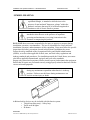
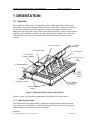
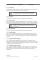
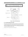
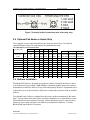
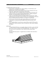
Installation and Operations Manual — Model 820 Series INTRODUCTION MODEL 820 SERIES SHALLOW MOUNT PLATE BARRIER INSTALLATION MANUAL B&B ARMR Corporate Office & Tech Support: 2009 Chenault Drive Carrollton, TX 75006 Suite 114 Phone: (972) 385-7899 Toll Free: (800) 367-0387 Fax: (972) 385-9887 E-mail: [email protected] [email protected] www.bb-armr.com MADE IN THE USA B&B ARMR A Division of B&B Roadway and Security Solutions 0820 Revision A2 Installation and Operations Manual — Model 820 Series ii INTRODUCTION Your safety is extremely important to us. If you have any questions or are in doubt about any aspect of the equipment, please contact us. INTRODUCTION Welcome! Congratulations on your purchase of a B&B ARMR vehicle barrier. In addition to providing detailed operating instructions, this manual describes how to install, maintain, and troubleshoot your vehicle barrier. If you require additional assistance with any aspect of your vehicle barrier's installation or operation, please contact us. With years of experience in all aspects of perimeter security and related disciplines, our products are used throughout the world to control access and to protect people, equipment, and facilities. We offer a broad range of vehicle barrier and related security services: Turnkey installations Routine barrier preventative maintenance or emergency repairs (including work on non-B&B ARMR products) Spare or replacement parts Custom designs or special installations Equipment upgrades (modernize your old equipment with state-of-the-art hydraulics and control systems) Ancillary security equipment such as security guard enclosures, card readers, security lighting, and many other security related products. Safety B&B ARMR A Division of B&B Roadway and Security Solutions 0820 Revision A2 Installation and Operations Manual — Model 820 Series iii INTRODUCTION SYMBOL MEANING: The lightning flash with arrowhead symbol, within an equilateral triangle, is intended to alert the user to the presence of non insulated "dangerous voltage" within the product's enclosure that may be of sufficient magnitude to constitute a risk of electric shock to persons. The exclamation point within an equilateral triangle is intended to alert the user to the presence of important operating and maintenance (servicing) instruction in the literature accompanying the product. B&B ARMR does not assume responsibility for injury to persons or property during installation, operation, or maintenance. The user is responsible for correct and safe installation, operation, and maintenance of this equipment. Users must follow the specific instructions and safety precautions located in this manual. In addition they must: Follow the safety standards of the Occupational Safety and Health Administration (OSHA), as well as other applicable federal, state, and local safety regulations and industry standards and procedures. For installation outside the United States, users must also follow applicable international, regional, and local safety standards. Engage only trained and experienced staff to install, operate, and maintain the equipment. Ensure that all repairs are performed correctly using properly trained technicians with the correct tools and equipment. This barrier comes with a Safety Lock Brace. Use this brace during any maintenance operations when barrier is in the up position. Failure to use this brace during maintenance can result in serious injury or death. Additional safety devices may be included with this barrier system: o Vehicle loop detector(s) – Safety loop o Traffic arms & lights o IR beams B&B ARMR A Division of B&B Roadway and Security Solutions 0820 Revision A2 Installation and Operations Manual — Model 820 Series iv INTRODUCTION How to Contact Us If you have any questions or experience any problems with your vehicle barrier or if we can help you with any other facility security issues please contact us directly at: Corporate/Tech Support: B&B ARMR 2009 Chenault Drive Suite 114 Carrollton, TX 75006 USA Telephone: (972) 385-7899 Toll Free: (800) 367-0387 Fax: (972) 385-9887 E-mail: [email protected] [email protected] System Installation Record To assist in documenting the products installed in your system, please take a minute to record the following reference information. This information can be located on the blue B&B ARMR model number plate located on the product in the cylinder access area. Additional columns are added for your convenience in documenting other components in the system. Site: Job #: Date: Serial Number: Model Number: Voltage: Phase: B&B ARMR A Division of B&B Roadway and Security Solutions 0820 Revision A2 Installation and Operations Manual — Model 820 Series TABLE OF CONTENTS Table of Contents INTRODUCTION .................................................................................................................. ii Safety......................................................................................................................................... ii How to Contact Us ................................................................................................................... iv System Installation Record ....................................................................................................... iv 1 ORIENTATION .............................................................................................................. 6 1.1 2 Overview ........................................................................................................................................................... 6 INSTALLATION ............................................................................................................. 8 2.1 Introduction....................................................................................................................................................... 8 2.2 Site Preparation .............................................................................................................................................. 10 2.3 Positioning ...................................................................................................................................................... 11 2.4 Rebar and Conduit Installation ....................................................................................................................... 12 2.5 Concrete .......................................................................................................................................................... 13 2.6 Hydraulic Connections.................................................................................................................................... 13 2.7 Proximity Switch Connection .......................................................................................................................... 14 2.8 Optional Pad Heater or Heater Strip .............................................................................................................. 15 2.9 Bellows Installation......................................................................................................................................... 15 2.10 3 Final Pre-operation Checklist ................................................................................................................... 17 TROUBLESHOOTING................................................................................................. 18 3.1 Model 820 Troubleshooting Guide.................................................................................................................. 18 4 WARRANTY ................................................................................................................... 20 5 APPENDIX ..................................................................................................................... 21 5.1 Exploded View parts List ................................................................................................................................ 21 5.2 Simplified Standard Hydraulic Diagram......................................................................................................... 22 B&B ARMR A Division of B&B Roadway and Security Solutions 0820 Revision A2 5 Installation and Operations Manual — Model 820 Series TABLE OF CONTENTS 5 1 ORIENTATION 1.1 Overview The model 820 vehicle barrier is designed to contain a high-speed vehicle impact and prevent that vehicle from entering a restricted access control area. The barrier consists of a cast in place foundation frame, raising plate with locking linkage, and associated hardware to allow the plate to move from a horizontal position to a raised, secure position with the aid of a hydraulic cylinder. The unit is designed for a shallow excavation, and includes all necessary accesses for drains, hydraulic conduits and electrical services required. 1.1.2. Attack Plate 1.1.9. Link Arm Bearings 1.1.4. Access Cover 1.1.3. Link Arms 1.1.8. Electrical Conduit Couplings ¾” 1.1.10. Center Lift Link Arm Bushing 1.1.5. Bearing Blocks 1.1.1 Base Support Frame 1.1.7. Hydraulic Conduit Couplings, 3" thread 1.1.11. Bellows (Uninstalled Position) 0820-2700 1.1.6. Drains 2.5" Thread Figure 1: Model 820 Shallow Mount Plate Barrier Figure 1 orients you to the basic components of the Model 820 vehicle barrier: 1.1.1 Base Support Frame The welded steel base support frame is engineered to distribute the crash impact load over a large area of soil surface. Coupled with the specified concrete base, the support frame ensures the barrier does not move on impact. B&B ARMR A Division of B&B Roadway and Security Solutions 0820 Revision A2 Installation and Operations Manual — Model 820 Series 1.1.2 INSTALLATION 7 Attack Plate The attack plate absorbs the impact load of the vehicle and allows a smooth surface for vehicles to roll over when the barrier is in the down position. CAUTION: This barrier is made of heavy steel components. Ensure all personnel are cleared of area during operation. 1.1.3 Link Arms The link arms tie the attack plate to the base support frame during impact. 1.1.4 Access Cover The access cover allows maintenance personnel to work on the hydraulic connections without having to be physically under the attack plate. Access to hydraulic cylinder and the proximity switch can be made by removal of the cover with a ½ inch allen wrench. CAUTION: Hydraulic cylinder and hoses are under extreme pressure. Use caution when working on barrier with access cover removed. 1.1.5 Bearing Blocks The bearing blocks aide in the support and adjustment of the attack plate. 1.1.6 Drain Couplings The 2 ½” drain couplings are provided to allow easy installation of drain pipe to the barrier. It is critical to the operation of the barrier that water drain out from inside the base support structure. Seal all unused drains prior to installation of the base support structure. 1.1.7 Hydraulic Conduit Couplings The 3” hydraulic conduit couplings provide easy interface for conduit to run the hydraulic hoses through. Hydraulic hoses and electrical wires should be run in separate conduits to avoid any chaffing of wires during barrier operation. Seal all unused conduit couplings prior to base support installation. 1.1.8 Electrical Conduit Couplings The ¾” electrical couplings are provided to run all electrical wires. Proximity switch wires should be run in their own conduit to assure no EMI noise affects the proximity switch signals. Seal all unused conduit couplings prior to base support structure installation. B&B ARMR A Division of B&B Roadway and Security Solutions 0820 Revision A2 Installation and Operations Manual — Model 820 Series 1.1.9 INSTALLATION 8 Link Arm Bearings The link arm bearings provide an anti-friction surface for the link arms to rotate on. Some bearings may require lubrication. 1.1.10 Center Lift Link Arm The center link arm provides the drive link to lift the attack plate. 1.1.11 Bellows The bellows provides a soft barrier to ensure debris does not blow or wash into the barrier. Although the bellows keeps the majority of the debris out of the base support frame, routine maintenance is required to keep the barrier clean and free of trash, rocks, and other foreign objects. 1.1.12 Options The Model 820 vehicle barrier is available with a broad array of options and field installed kits. Consult your ordering documentation to determine whether your system has the optional equipment. Base support structure heater wire. This optional kit includes the necessary components to add field installed heater strips around the base support frame prior to installation. This is highly recommended for areas where ice or snow may inhibit the performance of the barrier. A traffic control gate arm to warn the vehicle operator. This gate arm is positioned on the attack side of the barrier and does not open to allow traffic until the barrier is fully lowered (stowed), and the gate lowers to block traffic before the barrier starts to rise (deploy). Red/amber traffic lights. The light remains red if the gate is in any position except fully open. Infrared safety beams to detect pedestrian traffic or as an additional vehicle sensing device. 2 INSTALLATION 2.1 Introduction This section of the manual describes the procedure to set-up and configure the Model 820 Shallow Mount vehicle barrier for first-time operation. The product ships from the factory tested and ready for deployment following these steps. DANGER: High voltage electrical components are located in the Hydraulic Pumping Unit (HPU) cabinet. Service by qualified technicians only. B&B ARMR A Division of B&B Roadway and Security Solutions 0820 Revision A2 Installation and Operations Manual — Model 820 Series INSTALLATION 9 CAUTION: Heavy components and pinch points are present in this product. Use extreme care when servicing this unit. NOTE: The hydraulic hoses are constructed with JIC fittings to allow removal and installation without sealant. Care should be used when disconnecting the pressure side of the hose to insure the pressure has been released prior to disconnecting the fitting. The pressure can be relieved by activating the down control button and visually watching the cylinder shaft retract into the cylinder and the attack plate is in the completely lowered position. Prior to working on unit in UP position, insert supplied Safety Lock Brace to ensure attack plate does not move inadvertently. Safety Lock Brace Figure 2: Safety Lock Brace Location B&B ARMR A Division of B&B Roadway and Security Solutions 0820 Revision A2 Installation and Operations Manual — Model 820 Series INSTALLATION 10 2.2 Site Preparation The Model 820 Shallow Mount Barrier’s performance can be influenced by the surrounding soil conditions and grade. It is expected that the minimum soil compression force is 1600 PSF in and around the installation area. Please consult with B&B ARMR Technical Support if there are questions in regards to the installation site conditions. The following lists some recommendations related to site choice and preparation: 1. The 820 barrier is powered by hydraulic pressure from a remotely located Hydraulic Pumping Unit (HPU). It is critical the HPU and 820 barrier be within proximity to ensure any pressure drop in the hydraulic lines is minimal. Consult B&B ARMR Technical Support if HPU location is further than 30 feet from barrier. 2. Soil compressive strength under barrier shall be a minimum of 1600 PSF. Compact and add gravel where necessary to ensure solid soil base. Consult B&B ARMR Technical Support if soil compressive strength does not meet this minimum requirement. 3. Install barrier in area that has adequate drainage. Barrier’s operational performance is affected when there is inadequate drainage. 4. The barrier operates best when installed on a level surface. Slight inclines from attack side are acceptable, but inclines left and right may degrade barrier operational performance when opening and closing. Level site side to side prior to barrier installation. 5. Excavate install site to accommodate a minimum concrete pad dimension shown in table to match the size of the barrier you have purchased. If site excavation can not be completed per these minimum dimensions, please contact B&B ARMR Technical Support for a custom solution to meet the site requirements. Table 1. Concrete Pad Dimensions for Single 820 Barriers Model Size (Feet) 7 8 9 10 11 12 13 14 Concrete Pad Dimensions Width (in) 118.5 130.5 142.5 154.5 166.5 178.5 190.5 202.5 Length (in) 198 198 198 198 198 198 198 198 B&B ARMR A Division of B&B Roadway and Security Solutions Depth (in) 16 16 16 16 16 16 16 16 Estimated Concrete Required (Cubic Yards) 8.1 8.9 9.7 10.5 11.3 12.1 12.9 13.8 Estimated Lift Weight (Lbs) 4631 4863 6387 6624 6854 7091 8507 8739 0820 Revision A2 Installation and Operations Manual — Model 820 Series INSTALLATION 11 Figure 3 Barrier Concrete Pad Dimensions 2.3 Positioning 1. Position barrier using cinder blocks or similar product to ensure all four corners of the barrier are co-planer within 1/8”. Shim if necessary. It is critical to the operational performance of the barrier that the base support frame is not twisted. Four lifting holes are supplied near the corners of the barrier for lifting and positioning use (see figure 4). 2. Barrier position should be level within ¼” from left to right when viewing from attack side. Barrier may be mounted on an incline in attack direction. 3. Locate barrier in center of concrete pad site as shown in figure 3. B&B ARMR A Division of B&B Roadway and Security Solutions 0820 Revision A2 Installation and Operations Manual — Model 820 Series INSTALLATION 12 Lifting Holes Figure 4 Barrier Lifting Holes Drains 3/4" Couplings for electrical 3" Coupling for hydraulic hoses Figure 5 Conduit couplings 2.4 Rebar and Conduit Installation 1. Install drain conduits to enable positive flow away from barrier. Multiple drain conduit couplings are provided (See figure 5). Seal unused conduit drain couplings to ensure concrete does not fill drain tubes. 2. Install hydraulic hose conduits utilizing couplings provided. Seal all unused conduits to ensure concrete does not enter conduits. 3. Install electrical conduit utilizing the provided couplings. Seal all unused couplings prior to concrete installation. B&B ARMR A Division of B&B Roadway and Security Solutions 0820 Revision A2 Installation and Operations Manual — Model 820 Series INSTALLATION 13 4. Raise attack plate and brace using Safety Lock Brace. If hydraulic pump is already installed, run temporary hydraulic lines to barrier to raise attack plate. See section on hydraulic line connections for details. If HPU is not available, remove hydraulic cylinder plug, attach ¾-10 UNC lifting eye in attack plate and lift using crane or forklift. Use lifting eye rated above 5000lbs. Ensure shipping plugs in hydraulic cylinder are loosened to allow cylinder shaft to extend. CAUTION: Heavy components and pinch points are present in this product. Use extreme care when servicing this unit. Use Safety Lock Brace when performing installation of maintenance. 5. Set #4 rebar in 12” center cross patterns in pad. Slide the rebar into base support frame holes to ensure frame is rigidly attached to concrete pad. There is no need to weld the rebar to the frame. 6. If optional heater kit has been purchased, install heater core cable per kit instructions at this time prior to pouring concrete. 2.5 Concrete 1. Concrete shall be rated at 3000 psi or higher. 2. Assure concrete does not flow into trough areas or on bellows material. 3. Finish concrete level to within .125” of top section of link arm troughs and bellows troughs inside the base support frame. Assure the concrete does not extend higher than the top sections of the troughs. The attack plate is required to rest on the metal sections and not hit the concrete. 4. Finish concrete around front and back sections of barrier flush with top surface of steel base structure. 5. Vibrate concrete to assure all air bubbles and voids are removed under and around barrier. 6. When cleaning job site, do not use high pressure washer on anti-skid surface as it may lift coating. 2.6 Hydraulic Connections Connect hydraulic lines through conduit to cylinder connection using JIC fittings shown in figure 6. As a reference, use environmentally safe oil Mobil EAL 224 or equivalent when adding hydraulic oil to the HPU. Reference the HPU user manual to see detailed information. Prior to full operation the hydraulic lines and hydraulic cylinder must have its entrapped air bled out. B&B ARMR A Division of B&B Roadway and Security Solutions 0820 Revision A2 Installation and Operations Manual — Model 820 Series INSTALLATION 14 CAUTION: The hydraulic system when in operation is under extreme pressure. Verify pressure on the barrier is completely relieved prior to removal of any hydraulic fittings. Figure 6 Cylinder and Proximity switch 2.7 Proximity Switch Connection The proximity switch is adjusted in the factory and should require no further adjustment. To connect the proximity switch, use the included proximity switch connector and screw onto back end of proximity switch. Route wires clear of cylinder travel and pinch points. Once power is applied, the proximity switch will show a red LED light on when switch is closed and no LED light when switch is open. Proximity switch wire connections are shown in figure 7. B&B ARMR A Division of B&B Roadway and Security Solutions 0820 Revision A2 Installation and Operations Manual — Model 820 Series INSTALLATION 15 Figure 7 Proximity Switch Connections (wire colors may vary) 2.8 Optional Pad Heater or Heater Strip If so equipped, connect optional pad heater per heater kit instructions. See table for estimated lengths and power requirements for standard heater strip. Recommended Concrete Heater Runs Type: SRM/E 20-2C Barrier Model Number Watts/Foot 24.4 18.4 17.6 50F Start-Up 277VAC 220VAC 208VAC 277VAC 220VAC 208VAC Length of Barrier Heat Trace Required Required Required Size Cable Power Current Power Current Power Current Recommended Recommended Recommended (Ft) (Ft) (Watts) (Amps) (Watts) (Amps) (Watts) (Amps) Breaker Rating Breaker Rating Breaker Rating 820S-72 6 50 1220 4.4 920 4.2 880 4.2 15 15 15 820S-96 8 54 1318 4.8 994 4.5 950 4.6 15 15 15 820-84 7 54 1318 4.8 994 4.5 950 4.6 15 15 15 820-96 8 56 1366 4.9 1030 4.7 986 4.7 15 15 15 820-108 9 58 1415 5.1 1067 4.9 1021 4.9 15 15 15 820-120 10 78 1903 6.9 1435 6.5 1373 6.6 15 15 15 820-132 11 80 1952 7.0 1472 6.7 1408 6.8 15 15 15 820-144 12 82 2001 7.2 1509 6.9 1443 6.9 15 15 15 820-156 13 101 2464 8.9 1858 8.4 1778 8.5 15 15 15 820-168 14 103 2513 9.1 1895 8.6 1813 8.7 15 15 15 2.9 Bellows Installation The Model 820 bellows is designed to provide an aesthetic curtain for the barrier when it is in the deployed (up) position. B&B ARMR recommends monthly barrier preventative maintenance to ensure the bellows is kept clean and properly adjusted. Operational speed of the barrier to stow (down) may be adjusted to accommodate operation with an installed bellows. The optional barrier bellows is shipped from the factory without attachment to the attack plate. Test operation of the barrier prior to bellows installation is recommended to ensure all installation has been completed correctly. Minor adjustments may be required on the bellows to ensure proper operation for different environmental conditions. Consult a B&B ARMR representative if required. B&B ARMR A Division of B&B Roadway and Security Solutions 0820 Revision A2 Installation and Operations Manual — Model 820 Series INSTALLATION 16 To install bellows follow these steps. 1. Ensure bellows is attached to base support frame by ¼-20 UNC bolts or self tapping screws around the lower perimeter. 2. Ensure bellows has three batons installed in the first three folds below the cross support bar. Batons slide in from the sides of the bellows. 3. Verify the bellows brace is installed in the base support frame and bolted to the bellows cross brace (See figure) through folded material. Bellows cross brace should be riveted along bellows flaps using peel-type rivets. 4. Using ¼-20 UNC bolts, bolt bellows material to bottom of attack plate. Match drill clearance holes in bellows upper mounting area by slitting bellows with razor blade and drilling underlying aluminum cross support if not predrilled. 5. Drill four holes in the front tray under the plate placing one in each forward corner and two evenly spaced in the middle to bolt down the bellows to the ground. 6. Cycle completed barrier several times to ensure bellows material folds correctly during closure. Barrier speed may need to be adjusted to ensure proper folding of the bellows. RETROFIT: - To retrofit Model 820 barrier not originally shipped with bellows option, drill and tap 3/8” hole for bolt as shown in the following drawing. Use washers to space the bellows brace in a position as to not contact the barrier frame during operation. - The attack plate may require ¼” tapped holes to be drilled to allow the bellows mounting. B&B ARMR A Division of B&B Roadway and Security Solutions 0820 Revision A2 Installation and Operations Manual — Model 820 Series INSTALLATION 17 Bellows Top Mount /Attack Plate Bellows Bellows Cross Brace Rivets Batons Bellows Brace 1.00 .375 -16 BOLT QTY 1 .375 FLAT WASHER QTY 5 ( BOLT REQUIRED FOR RETROFIT ONLY) 2.25 Bellows Brace Figure 8 Bellows Brace 2.10 Final Pre-operation Checklist Before operating the Model 820 vehicle barrier, go through the checklist below and verify that each of these steps has been completed. CAUTION: For your safety, complete each of these steps before operating the barrier! B&B ARMR A Division of B&B Roadway and Security Solutions 0820 Revision A2 Installation and Operations Manual — Model 820 Series INSTALLATION 18 Verify unit has hydraulic fluid to recommended level. Verify control unit is plugged in and cable is routed clear of barrier operation. Verify area is clear of personnel and other obstructions. Ensure supplied power to HPU matches product requirements. Verify electrical hookups are completed per electrical wiring diagram matching particular product. It is recommended the unit be cycled 4 complete cycles prior to vehicle or pedestrian traffic. 3 TROUBLESHOOTING The table below provides a general guidance on identifying and correcting any problems with your Model 820 Series vehicle barrier. If you encounter problems that you cannot fix, contact B&B ARMR and we will gladly work with you to correct them. 3.1 Model 820 Troubleshooting Guide The table below provides guidance on identifying and correcting any problems with your Model 820 Series vehicle barrier. Please refer to the HPU O&M manual for more detailed troubleshooting guides referring to the pumping unit. If you encounter problems that you cannot fix, contact B&B ARMR and we will gladly work with you to correct them. Symptom Barrier does not raise up when commanded on control panel Barrier does not close when commanded on control panel Actions 1. Check power 2. Check overload protector 3. Check PLC output on pumping unit 4. Check that safeties are clear. 5. Check push button operation 6. Check PLC input on pumping unit. 7. Check pressure gauge 8. Manually raise the barrier by depressing the directional control valve to see if problem is mechanical or electrical. 9. Check for binding between moving plate and frame. Check connection of linkage between frame and plate. Check for debris. 1. Check power 2. Check PLC output on pumping unit 3. Check that safeties are clear. 4. Check push button operation 5. Check PLC input on pumping unit. 6. Check for binding between moving plate and frame. Check connection of linkage between frame and plate. Check for B&B ARMR A Division of B&B Roadway and Security Solutions 0820 Revision A2 Installation and Operations Manual — Model 820 Series Symptom HPU pump will not build up pressure but is running HPU pump will not turn on Barrier makes noise during operation Actions debris. 1. Check power 2. Close pressure relief valve 1. 2. 3. 4. 5. 1. 2. 3. 1. Hydraulic unit excessively hot Barrier moves too slowly Traffic indicator light does not change TROUBLESHOOTING 2. 3. 1. 2. 3. 1. 2. 3. Check power Check motor overload, press start. Check motor starter. Check low level switch. Check pressure switch. Check linkage between frame and plate. Be sure it is secured and properly lubricated (see maintenance check sheet). Check hinge area for debris and proper lubrication (see maintenance check sheet). Check hydraulic cylinder clevis pins for lubrication (see maintenance check sheet). Check that the pressure relief valve is closed (fully clockwise). Check that the pressure switch is adjusted to shut the motor off before 1900 PSI. Check for correct voltages. Check for mechanical binds. Check flow control valve. In extreme cold temperatures, a higher grade hydraulic fluid may be required to keep viscosity constant. Check bulbs. Check PLC outputs. Check proper limit switch operation. B&B ARMR A Division of B&B Roadway and Security Solutions 0820 Revision A2 19 Installation and Operations Manual — Model 820 Series WARRANTY 20 4 WARRANTY BBRSS warranties for a period of one (1) year FOB manufacturing facility, unless otherwise specified by BBRSS in writing, from defects due to faulty material or workmanship. Damage due to handling during shipment and installation are not covered under warranty. BBRSS assumes no responsibility for service at customer site. BBRSS is in no event responsible for any labor costs under the warranty. Subject to the above limitation, all service, parts, and replacements necessary to maintain the equipment as warranted shall be furnished by others. BBRSS shall not have any liability under these specifications, other than for repair or replacement as described above for faulty product material or workmanship. Equipment malfunction or equipment failure of any kind, caused for any reason, including, but not limited to unauthorized repairs, improper installation, installation not performed by BBRSS authorized personnel, incoming supply power is outside the tolerance for the product, failure to perform manufacturer’s suggested preventative maintenance, modifications, misuse, accident, catastrophe, neglect, natural disaster, are not under warranty. The exclusive remedy for breach of any warranty by BBRSS shall be the repair or replacement at BBRSS’s option, of any defects in the equipment. IN NO EVENT SHALL BBRSS BE LIABLE FOR CONSEQUENTIAL OR SPECIAL DAMAGES OR ANY KIND OF PERSONAL DAMAGES. Except as provided herein, BBRSS makes no warranties or representations to consumer or to anyone else and consumer hereby waives all liability against BBRSS as well as any other person for the design, manufacture, sale, installation, and/or servicing of the Products. THE FOREGOING WARRANTIES ARE IN LIEU OF ALL OTHER WARRANTIES EXPRESS OR IMPLIED, INCLUDING THE IMPLIED WARRANTY OF MERCHANTABILITY AND FITNESS FOR A PARTICULAR PURPOSE. NO OTHER WARRANTIES EXIST. Any modification or alteration by anyone other than BBRSS will render the warranty herein as null and void. B&B ARMR A Division of B&B Roadway and Security Solutions 0820 Revision A2 Installation and Operations Manual — Model 820 Series APPENDIX 21 5 APPENDIX 5.1 Exploded View parts List B&B ARMR A Division of B&B Roadway and Security Solutions 0820 Revision A2 Installation and Operations Manual — Model 820 Series APPENDIX 22 5.2 Simplified Standard Hydraulic Diagram The following figure shows a typical hydraulic schematic for a 611X HPU. The schematic shown is for a single lane barrier system using a cylinder. SIMPLIFIED STANDARD HYDRAULIC SCHEMATIC CYLINDER CONTROL EFO MANIFOLD PRESSURE SWITCH a PRESSURE GAUGE FLOW CONTROL VALVE a M MOTOR MANUAL VALVE PUMP ACCUMULATOR INTERNAL PUMP RELIEF SYSTEM PRESSURE RELIEF VALVE P B T A FLOW CONTROL VALVES CYLINDER b DIRECTIONAL CONTROL VALVE FIELD HOSES RESERVOIR Revision B B&B ARMR A Division of B&B Roadway and Security Solutions 0820 Revision A2