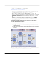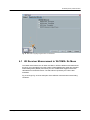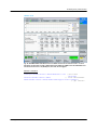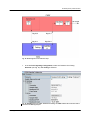
1
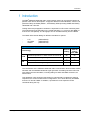
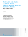
Testing UEs under Fading Conditions with the R&S®CMW500 RF Tester and the R&S®AMU200A Application Note Products: | R&SCMW500 | R&SAMU200A Bernhard Schulz March 2013 – 1MA194_0e Application Note This application note shows how to perform user equipment (UE) receiver tests, such as block error rate (BLER) and throughput tests, under fading conditions with the R&S®CMW500 RF tester and the R&S®AMU200A fading simulator in LTE and W-CDMA (HSPA+). Table of Contents 1MA194_0e 1 Introduction ............................................................................ 3 2 Measurement Setup ............................................................... 5 2.1 Overview........................................................................................................5 2.1.1 Fading Test Setup for One Baseband ........................................................5 2.1.2 Fading Test Setup for Two Basebands ......................................................6 2.2 AMU Configuration .......................................................................................7 3 LTE Measurements .............................................................. 19 3.1 UE Receiver Measurement in LTE: Extended BLER ...............................19 3.2 SISO Configuration ....................................................................................22 3.3 Rx Diversity (1x2 SIMO) Configuration ....................................................25 3.4 Tx Diversity (2x1 MISO) Configuration .....................................................30 3.5 Spatial Multiplexing (2x2 MIMO) Configuration .......................................34 4 W-CDMA (HSPA+) Measurements ...................................... 39 4.1 UE Receiver Measurement in W-CDMA: Rx Meas...................................40 4.2 SISO Configuration ....................................................................................43 4.3 Dual-Carrier Configuration (DC-HSPA+) ..................................................47 4.4 DC-HSPA+ with Rx Diversity .....................................................................50 5 Data Application Unit (DAU) ................................................ 55 5.1 LTE ...............................................................................................................58 5.2 W-CDMA (with HSPA+) ..............................................................................58 6 Appendix ............................................................................... 61 6.1 Literature .....................................................................................................61 6.2 Additional Information ...............................................................................61 6.3 Ordering Information .................................................................................62 Rohde & Schwarz Testing UEs under Fading Conditions with CMW500 and AMU200A 2 Introduction 1 Introduction ® The R&S CMW500 wideband radio communication tester can be used throughout all phases of UE device development. It supports different mobile standards, such as LTE (FDD and TDD), W-CDMA (HSPA+, TD-SCDMA), GSM (including GPRS and EDGE), cdma2000 and 1xEV-DO. Testing under real propagation conditions is important for UE receiver sensitivity tests. The measurement type depends on the mobile standard, e.g. a bit-error rate (BER) or a block-error rate (BLER). The throughput can be calculated directly from the BLER. The CMW offers internal fading for different standards as options: - LTE W-CDMA AWGN (CMW-KE500) (CMW-KE400) (CMW-KE100) Supported fading Technology LTE Predefined profiles acc. 3GPP.TS 36.101 Annex B External Fading with AMU Full user-defined fading settings Predefined profiles acc. 3GPP.TS 25.101 Annex B 3G Internal Fading Full user-defined fading settings The combination of the CMW500 wideband radio communication tester as base station simulator and the AMU200 baseband signal generator and fading simulator offers full user-defined channel simulation, including fading for SISO and MIMO scenarios, as well as noise. This application note shows the test setups for external fading, explains the settings required for the various measurement configurations, such as Rx diversity and MIMO for both LTE and W-CDMA. In addition, it specifies the most important remote commands along the way. 1MA194_0e Rohde & Schwarz Testing UEs under Fading Conditions with CMW500 and AMU200A 3 Introduction ® The following abbreviations are used in the following text for R&S test equipment: 1MA194_0e ® The R&S CMW500 wideband radio communication tester is referred to as CMW. ® The R&S AMU200A baseband signal generator and fading simulator is referred to as AMU. ® R&S refers to Rohde & Schwarz GmbH und Co KG. Rohde & Schwarz Testing UEs under Fading Conditions with CMW500 and AMU200A 4 Measurement Setup 2 Measurement Setup 2.1 Overview Fading and AWGN characteristics are applied in the AMU. To do this, it is necessary to feed the CMW’s digital baseband signals through the AMU. Here, a single or first signal is fed through DIG IQ OUT 2 via Baseband A and DIG IQ IN/OUT 1. A second signal is sent accordingly through DIG IQ OUT 4 via Baseband B and DIG IQ IN/OUT 3. Fig. 2 shows the CMW digital baseband connection. A single signal (SISO tests or one carrier) needs input and output A, while using two signals (MIMO or dual carrier) requires input and output A and B. From AMU (digital baseband out) B A To AMU (digital baseband in) A Fig. 1: CMW: Digital In / Out. Detailed configuration information for the AMU and CMW can be found at the end of this application note. 2.1.1 Fading Test Setup for One Baseband The following figure shows the setup for SISO-based measurements. 1MA194_0e Rohde & Schwarz Testing UEs under Fading Conditions with CMW500 and AMU200A 5 B Measurement Setup CMW RF 1 COM UE Dig.Baseband Out / In LAN Remote Ref1 Out 1 A A Ref In AMU Fig. 2: Hardware configuration for LTE terminal test under SISO fading conditions. The AMU fading simulator is connected to the CMW via the digital baseband input and output A. 2.1.2 Fading Test Setup for Two Basebands The following figure shows a setup with two baseband signals, which is required for scenarios using two basebands, such as MIMO or dual carrier. Please note that there are two possible configurations for the RF frontends available: ● Two FE basic (FE1 basic (CMW-S590A) + FE2 basic (CMW-B590A)) Or ● 1MA194_0e One FE1 advanced (CMW-S590D) Rohde & Schwarz Testing UEs under Fading Conditions with CMW500 and AMU200A 6 Measurement Setup CMW RF 2 COM RF 1 COM UE Dig.Baseband Out / In A B A Ref1 Out LAN Switch 1 LAN Remote B Ref In AMU Fig. 3: Hardware configuration for LTE terminal test under MIMO fading conditions. The AMU fading simulator is connected to the CMW via two digital baseband inputs and outputs A and B. 2.2 AMU Configuration Changing the input level or fading profile settings on the AMU affects the insertion loss, and this must be compensated on the CMW as shown in 3.3.7 before a throughput measurement or any other measurement is performed! External reference The AMU needs to be synchronized by connecting the CMW Ref1 Out to the AMU Ref In. The AMU must be set to external reference in the following menu. Fig. 4: External reference. 1MA194_0e Rohde & Schwarz Testing UEs under Fading Conditions with CMW500 and AMU200A 7 Measurement Setup Digital input Two important criteria of the baseband signal are the crest factor and the PEP peak envelope power). The PEP of the digital LTE baseband signal coming from the CMW is defined as 0 dBFS (= dB Full Scale, the level ratio of the signal to the maximum possible voltage of I or Q, e.g. 0.5 Vp = 1 Vpp [peak to peak]). The crest factor is the ratio between the PEP and (RMS) LEVEL. PEP = 0 dBFS 0 dBFS Crest Factor = 13 dB RMS Level = -13 dB -13 dBFS Fig. 5: PEP, RMS level and crest factor. The LTE signal at the CMW digital baseband output depends on the mobile standard and is shown in the SIGNALING application under IQ Settings | Crest Factor. In the example in Fig. 6, it is 15 dB. Fig. 6: The Crest factor depends on the mobile standard, and the CMW indicates its value. The crest factor must be taken into account when adjusting the digital input to the AMU. The AMU BB Input A (and B for MIMO) must be set to 0 dBFS PEP, and the crest factor must be set as determined above (15 dB in this example). 1MA194_0e Rohde & Schwarz Testing UEs under Fading Conditions with CMW500 and AMU200A 8 Measurement Setup Fig. 7: AMU Baseband Input Settings. Remote commands: SOURce1|2:BBIN:STATe ON SOURce1|2:BBIN:MODE DIGital SOURce1|2:BBIN:SRATe:SOURce USER SOURce1|2:BBIN:SRAT 100MHz SOURce1|2:BBIN:CFACtor 15.00 SOURce1|2:BBIN:POWer:PEAK 0.00 // // // // // // Turn Baseband A|B Inp. ON Select Digital Input Mode Select Digital Input Mode 100 MHz sample rate Set 15 dB Crest Factor Set 0 dBFS PEP Digital output The digital I/Q output A (and B for MIMO) must be turned ON, and the PEP must be set to the same value as at the input (0.00 dBFS). Set the output sample rate to 100 MHz. 1MA194_0e Rohde & Schwarz Testing UEs under Fading Conditions with CMW500 and AMU200A 9 Measurement Setup Fig. 8: Digital I/Q Output Settings. Remote commands: SOURce1|2:IQ:OUTPut:DIGital:SRATe:SOURce USER SOURce1|2:IQ:OUTPut:POWer:VIA PEP SOURce1|2:IQ:OUTPut:DIGital:POWer:PEP 0 // Set PEP = 0 dBFS SOURce1|2:IQ:OUTPut:DIGital:STATe ON // BB A|B dig. outp ON Display settings In the I/Q OUT SETTINGS menu, select LEVEL DISPLAY SETTINGS… to easily read the output level and insertion loss. Fig. 9: Level Display Settings Set the AUXILIARY INFORMATION parameter in the LEVEL DISPLAY SETTINGS A (and B for MIMO) menu to CREST FACTOR ((S+N)/S). This crest factor indicates the ratio of the signal’s peak value plus noise to the signal’s RMS level without noise. Fig. 10: Level Display Settings Remote commands: SOURce1|2:IQ:OUTPut:DISPlay DIGItal SOURce1|2:IQ:OUTPut:POWer:VIA PEP SOURce1|2:IQ:OUTPut:DISPlay:AINFormation CFSN 1MA194_0e Rohde & Schwarz Testing UEs under Fading Conditions with CMW500 and AMU200A 10 Measurement Setup Fading settings In principle, up to two baseband signals can be subjected to fading and AWGN in the AMU. In addition, it is possible to select different MIMO configurations. For the fading functionality, there are pre-defined scenarios in line with the specifications of the various wireless standards (for example, LTE EVA 5 Hz). In such cases, there is no need to configure any further settings. In addition, for tests that go beyond these requirements, it is also possible to set all of the fading parameters individually. In the Fading block, configure the Fading Settings. You can either choose Standard to conveniently select predefined scenarios or choose User to modify the individual parameters by implementing custom settings. Fig. 11: Block Fading: fading settings. Remote command: SOURce1|2:FSIMulator:STANdard xxx 1MA194_0e Rohde & Schwarz Testing UEs under Fading Conditions with CMW500 and AMU200A 11 Measurement Setup Fig. 12: The selection of pre-defined fading profiles. Figure 13: AMU Path Table: Detailed settings for multiple paths. If a second path is used, also configure the fading accordingly in Path B. The AMU needs to know the CMW’s RF frequency in order to calculate Doppler-based fading standards correctly. This frequency, e.g. 2.646 GHz, must be entered in the VIRTUAL RF control. 1MA194_0e Rohde & Schwarz Testing UEs under Fading Conditions with CMW500 and AMU200A 12 Measurement Setup Fig. 14: Virtual RF Remote command: SOURce1|2:FSIMulator:FREQuency 2646MHz Turn fading ON. Remote command: SOURce1|2:FSIMulator:STATe ON MIMO Signals With tests that use MIMO, it is also necessary to fade the cross components between the antennas. For a 2x2 MIMO test, for example, it is necessary to simulate a total of four paths. Select 2X2 MIMO in the Fading A (or B) config… menu. Fig. 15: 2x2 MIMO scenario. Remote command: SOUR:FSIM:ROUT FA1A2BFB1A2BM24 Select the desired fading standards in the LTE MIMO menu, e.g. EPA 5 Hz Low (Enhanced Pedestrian A, low correlation), or use individual settings. 1MA194_0e Rohde & Schwarz Testing UEs under Fading Conditions with CMW500 and AMU200A 13 Measurement Setup Fig. 16: LTE-MIMO fading standards, Remote command: SOURce1|2:FSIMulator:STANdard LMEPA5L Fig. 17: 2x2 MIMO fading scenario. Note: 1MA194_0e A setting change in one of the fading blocks (Fading AA, AB, BA or BB) also always applies to all other blocks. Rohde & Schwarz Testing UEs under Fading Conditions with CMW500 and AMU200A 14 Measurement Setup AWGN settings Press Config… in AWGN/IMP A/B control and select AWGN… Fig. 18: Select the AWGN menu. In the AWGN menu, set the System Bandwidth (e.g. 10 MHz), the desired Signal/Noise Ratio (e.g. 0.00 dB) and turn the State ON. Fig. 19: The AWGN parameters. Remote commands: SOURce1|2:AWGN:MODE ADD SOURce1|2:AWGN:BWID 10 MHz SOURce1|2:AWGN:BWID:RAT 1.0 SOURce1|2:AWGN:DISP:ORES DIG SOURce1|2:AWGN:POWer:MODE SN SOURce1|2:AWGN:BRATE 100 kbps SOURce1|2:AWGN:SNR 0.0 dB SOURce1|2:AWGN ON 1MA194_0e Rohde & Schwarz Testing UEs under Fading Conditions with CMW500 and AMU200A 15 Measurement Setup Fig. 20: MIMO fading + AWGN. Insertion Loss Compensation A faded signal has a higher crest factor than an unfaded signal has. In order to avoid distortion, the signal must be attenuated before entering the fading unit. The necessary attenuation, aka insertion loss, depends on the fading standard and on the AWGN level. The insertion loss in the baseband must be compensated in the CMW. This can be done easily by setting the CMW IQ Input level to the calculated AMU IQ Output level. 1MA194_0e Rohde & Schwarz Testing UEs under Fading Conditions with CMW500 and AMU200A 16 Measurement Setup Fig. 21: AMU settings for SISO fading. In the CMW, allowance must be made for the resulting crest factor (without AWGN) in order to compensate the insertion loss. Remote command: SOURce1|2:IQ:OUTPut:DIGital:POWer:LEVel? Fig. 22: Making allowance for the insertion loss from the AMU in the CMW. Here, the AMU signal’s level (without AWGN) must be entered as the IQ In level. 1MA194_0e Rohde & Schwarz Testing UEs under Fading Conditions with CMW500 and AMU200A 17 Measurement Setup Note: 1MA194_0e The fading profile and AWGN settings should not be changed during an active LTE connection, since doing that affects the DL power, which may lead to a call drop. Always set the fading profile and AWGN before establishing the connection. Rohde & Schwarz Testing UEs under Fading Conditions with CMW500 and AMU200A 18 LTE Measurements 3 LTE Measurements With the LTE standard, the UE receiver measurements include BLER, throughput and channel quality index (CQI). All measurements are summarized in the Extended BLER measurement application (see 3.1). Before starting the LTE signaling, external fading must be selected as the scenario. Once signaling has begun, or once a connection has been established with the DUT, it is no longer possible to change scenarios. Different antenna configurations (transmission modes) are possible with LTE. These modes also require different ways of handling fading: LTE Scenarios LTE Scenario Purpose TM CMW Configuration SISO Standard 1 Standard cell fading SIMO RX Diversity 1 Two RF Out Ports Fading MISO TX Diversity 2 Two RF Out Ports Fading MIMO Spatial Multiplexing 3/4 Two RF Out Ports Fading Table 1: LTE scenarios in the CMW. This section describes the necessary steps to perform an LTE Rx measurement under several conditions, such as SISO or 2x2 MIMO fading. For further information on LTE signaling and extended BLER measurements, refer to [5]. 3.1 UE Receiver Measurement in LTE: Extended BLER The CMW sends data to the UE via PDSCH subframes and determines the block error rate (BLER) from the positive ACKnowledgments (ACK) and negative ACKnowledgments (NACK) returned by the UE. Additional throughput results are calculated from the BLER results. The CQI indices reported by the UE are also evaluated. Fig. 23 through Fig. 26 show examples of the different measurements under fading conditions. 1MA194_0e Rohde & Schwarz Testing UEs under Fading Conditions with CMW500 and AMU200A 19 LTE Measurements Fig. 23: LTE Extended BLER: overview. Fig. 24: LTE Extended BLER: Throughput 1MA194_0e Rohde & Schwarz Testing UEs under Fading Conditions with CMW500 and AMU200A 20 LTE Measurements Fig. 25: LTE Extended BLER: BLER Fig. 26: LTE Extended BLER: CQI Reporting Remote Command: CONFigure:LTE:SIGN<i>:EBLer:SFRames 10000 // set 10000 frames INITiate:LTE:SIGN<i>:EBLer // start measurement FETCh:LTE:SIGN<i>:EBLer:ABSolute? // get results(abs.) 1MA194_0e Rohde & Schwarz Testing UEs under Fading Conditions with CMW500 and AMU200A 21 LTE Measurements 3.2 SISO Configuration This configuration uses only one data stream via one antenna. For this, it is only necessary to fade one path, and that can be done with one of the AMU channels. Fig. 27: Block diagram for the SISO test setup. 1. In the LTE Signaling Configuration, select the Standard Cell Fading Scenario (seeFig 28). Set the Fading to External. 1MA194_0e Rohde & Schwarz Testing UEs under Fading Conditions with CMW500 and AMU200A 22 LTE Measurements Fig. 28: LTE scenario for SISO: Standard Cell Fading. The CMW indicates the crest factor, which is entered in the AMU’s Dig IQ Input. Remote command: // Standard Cell Fading external via RF2COM and IQ2 Out ROUTe:LTE:SIGN:SCENario:SCFading RF2C,RX1,RF2C,TX1,IQ2O // read out information of IQ settings SENSe:LTE:SIGN<i>:IQOut:PATH<n>? 2. Take note of the Crest Factor under IQ Out and enter this value in the AMU under Baseband Input Level (see Fig. 7 in section 2.2). 3. Set a fading and switch on I/Q Out A (see section 2.2). 4. In the CMW, enter the corresponding crest value, which is indicated by AMU (see Fig. 29 and Fig. 30). 5. Use CONNECT to establish an LTE connection between the CMW and DUT. 6. If you modify the fading, remember to change the crest factor accordingly in the CMW. 1MA194_0e Rohde & Schwarz Testing UEs under Fading Conditions with CMW500 and AMU200A 23 LTE Measurements Fig. 29: AMU settings for SISO fading. Allowance must be made in the CMW for the resulting crest factor in order to compensate for the insertion loss. Fig. 30: Making allowance for the insertion loss from the AMU in the CMW. Here, the level of the AMU signal is entered as the IQ In level. Remote command: // set IQ In to PEP 0 dBFS and Level -25 dBFS CONFigure:LTE:SIGN<i>:IQIN:PATH<n> 0.0, -25.0 1MA194_0e Rohde & Schwarz Testing UEs under Fading Conditions with CMW500 and AMU200A 24 LTE Measurements 7. Start the RX measurement using Extended BLER (see section 3.1). Fig. 31 shows an example of an SISO measurement in the overview. Fig. 31: LTE RX measurement for SISO. 3.3 Rx Diversity (1x2 SIMO) Configuration For Rx diversity, a signal sent from one antenna is received at the UE with two antennas. Consequently, it arrives via two different receive paths. No additional coding is employed on the transmitter end. Therefore, in order to perform the measurement under fading conditions, it is necessary to simulate two receiving paths. 1MA194_0e Rohde & Schwarz Testing UEs under Fading Conditions with CMW500 and AMU200A 25 LTE Measurements Fig. 32: CMW SIMO setup (Rx Diversity). Remote commands: // set Two RF Output Ports external Fading ROUTe:LTE:SIGN:SCENario:TROFading RF1C,RX1,RF1C,TX1,IQ2O,RF2C,TX2,IQ4ON // set transmission scheme to SIMO CONFigure:LTE:SIGN<i>:CONNection:TSCHeme SIMO 1MA194_0e Rohde & Schwarz Testing UEs under Fading Conditions with CMW500 and AMU200A 26 LTE Measurements Fig. 33: Block diagram for the SIMO test setup. The two receive paths are simulated using the same stream. 1. In the LTE Signaling Configuration, select the Two RF Out Ports Fading Scenario (see Fig. 34). Set Fading to External. Fig. 34: LTE Scenario for two RF out ports: Two RF Out Ports Fading. The CMW indicates the crest factors, which are entered in the AMU’s Dig IQ input. 1MA194_0e Rohde & Schwarz Testing UEs under Fading Conditions with CMW500 and AMU200A 27 LTE Measurements Remote command: // read out information of IQ settings SENSe:LTE:SIGN<i>:IQOut:PATH<n>? 2. Take note of both Crest Factors shown under IQ Out and enter the valuec in the AMU under Baseband Input Level A and B (see Fig. 7 in section 2.2). 3. Set a fading for both paths, and switch on I/Q Out A and B (see Fig. 35). 4. In the CMW, enter both of the crest factors indicated by the AMU (see Fig. 35 and Fig. 36). 5. Use CONNECT to establish an LTE connection between the CMW and the DUT. 6. If you modify the fading and/or AWGN, remember to adapt the CMW settings to reflect the changes in the crest factor. Fig. 35: AMU settings for fading two paths (SIMO and MISO). The resulting crest factors must be reflected in the CMW in order to compensate for the insertion loss. 1MA194_0e Rohde & Schwarz Testing UEs under Fading Conditions with CMW500 and AMU200A 28 LTE Measurements Fig. 36: Making allowance in the CMW for the insertion loss from the AMU. Here, the level of the AMU signal is entered as the IQ In level. Remote command: // set IQ In to PEP 0 dBFS and Level -25 dBFS CONFigure:LTE:SIGN<i>:IQIN:PATH<n> 0.0, -25.0 7. Use Extended BLER to start the RX measurement (see section 3.1). Fig. 37 shows an example of an SIMO measurement in the overview. Fig. 37: LTE RX measurement for Rx Diversity (SIMO). 1MA194_0e Rohde & Schwarz Testing UEs under Fading Conditions with CMW500 and AMU200A 29 LTE Measurements 3.4 Tx Diversity (2x1 MISO) Configuration To conduct the Tx diversity measurement, one signal is transmitted via two antennas using different coding in order to achieve greater robustness. Here, too, there are two different receive paths. Consequently, to take this measurement under fading conditions, it is necessary to simulate two different receive paths. Fig. 38: CMW MISO setup. Remote commands: // set Two RF Output Ports external Fading ROUTe:LTE:SIGN:SCENario:TROFading RF1C,RX1,RF1C,TX1,IQ2O,RF2C,TX2,IQ4ON // set transmission scheme to Transmit Diversity CONFigure:LTE:SIGN<i>:CONNection:TSCHeme TXDiversity 1MA194_0e Rohde & Schwarz Testing UEs under Fading Conditions with CMW500 and AMU200A 30 LTE Measurements Fig. 39: Block diagram for the MISO test setup. Using different coding, one stream is transmitted via two antennas. Consequently, it is necessary to simulate two receive paths. 1. In the LTE Signaling Configuration, select the Two RF Out Ports Fading Scenario (see Fig. 40). Set Fading to External. Fig. 40: LTE scenario for two RF out ports: Two RF Out Ports Fading. The CMW indicates the crest factors, which are entered into the AMU Dig IQ input. 1MA194_0e Rohde & Schwarz Testing UEs under Fading Conditions with CMW500 and AMU200A 31 LTE Measurements Remote command: // read out information of IQ settings SENSe:LTE:SIGN<i>:IQOut:PATH<n>? 2. Take note of the Crest Factors under IQ Out and enter the values in the AMU under Baseband Input Level A and B (see Fig. 7 in section 2.2). 3. Set a fading for both paths, and switch I/Q Out A and B on (see Fig. 41). 4. In the CMW, enter both of the crest factors indicated by the AMU (see Fig. 41 and Fig. 42). 5. Use CONNECT to establish an LTE connection between the CMW and DUT. 6. If you modify the fading and or AWGN, remember to change the crest factor accordingly in the CMW. Fig. 41: AMU settings for fading two paths (SIMO and MISO). In the CMW, allowance must be made for the resulting crest factors in order to compensate the insertion loss. 1MA194_0e Rohde & Schwarz Testing UEs under Fading Conditions with CMW500 and AMU200A 32 LTE Measurements Fig. 42: Compensating for the insertion loss from the AMU in the CMW. Here, the level of the AMU signal is entered as the IQ IN level. Remote command: // set IQ In to PEP 0 dBFS and Level -25 dBFS CONFigure:LTE:SIGN<i>:IQIN:PATH<n> 0.0, -25.0 7. Use Extended BLER to start the RX measurement (see section 3.1). Fig. 43 shows an example of an MISO measurement in the overview. Fig. 43: LTE RX measurement for Tx diversity (MISO). 1MA194_0e Rohde & Schwarz Testing UEs under Fading Conditions with CMW500 and AMU200A 33 LTE Measurements 3.5 Spatial Multiplexing (2x2 MIMO) Configuration With spatial multiplexing, two different streams are transmitted via two antennas in order to boost the data throughput rate. For the simulation, it is also necessary to take the cross components into account; consequently, it is necessary to simulate a total of four receive paths. Fig. 44: CMW MIMO setup. Remote commands: // set Two RF Output Ports external Fading ROUTe:LTE:SIGN:SCENario:TROFading RF1C,RX1,RF1C,TX1,IQ2O,RF2C,TX2,IQ4ON // set transmission scheme to Multiplexing Open or Closed Loop CONFigure:LTE:SIGN<i>:CONNection:TSCHeme OLSMultiplex|CLSMultiplex // set the Precoding Matrix to PMI1 CONFigure:LTE:SIGN<i>:CONNection:PMATrix PMI1 1MA194_0e Rohde & Schwarz Testing UEs under Fading Conditions with CMW500 and AMU200A 34 LTE Measurements Fig. 45: Block diagram for the MIMO test setup. Two streams are transmitted via two antennas. Consequently, in order to also take the cross components into account, it is necessary to simulate four receive paths. 1. In the LTE Signaling Configuration, select the Two RF Out Ports Fading Scenario (see Fig. 46). Set Fading to External. Fig. 46: LTE Scenario for two RF Out Ports: Two RF Out Ports Fading. The CMW indicates the crest factors that are entered in the AMU Dig IQ Input. 1MA194_0e Rohde & Schwarz Testing UEs under Fading Conditions with CMW500 and AMU200A 35 LTE Measurements Remote command: // read out information of IQ settings SENSe:LTE:SIGN<i>:IQOut:PATH<n>? 2. Take note of the Crest Factors under IQ Out, and enter the values in the AMU under Baseband Input Level A and B (see Fig. 7 in section 2.2). 3. Set the AMU to 2x2 MIMO, and switch I/Q Out A and B on (see Fig. 44). 4. Select an appropriate fading setting. The setting for Block AA is then automatically used for the other paths, too. 5. In the CMW, enter both crest factors indicated by the AMU (see Fig. 47 and Fig. 48). 6. Establish an LTE connection between the CMW and the DUT via CONNECT. 7. If you modify the fading and/or AWGN, remember to change the crest factor accordingly in the CMW. There are three correlation modes for EPA, EVA and ETU LTE fading settings in line with 3GPP specification TS36.101. Low = No correlation between path A and B faders. This results in the best throughput and BLER results. Medium = A and B are correlated to a certain degree, throughput decreases and BLER increases. High = Full correlation between A and B faders which annuls the improvement by MIMO. Fig. 47: AMU settings for fading four paths (2x2 MIMO). In order to compensate the insertion loss, it is necessary to make allowance of the resulting crest factors in the CMW. 1MA194_0e Rohde & Schwarz Testing UEs under Fading Conditions with CMW500 and AMU200A 36 LTE Measurements Fig. 48: Compensating the insertion loss from the AMU in the CMW. Here, the level of the AMU signal is entered as the IQ In level. Remote command: // set IQ In to PEP 0 dBFS and Level -28.01 dBFS CONFigure:LTE:SIGN<i>:IQIN:PATH<n> 0.0, -28.01 8. Use Extended BLER to start the RX measurement (see section 3.1). Fig. 49 shows an example of an MISO measurement in the overview. 1MA194_0e Rohde & Schwarz Testing UEs under Fading Conditions with CMW500 and AMU200A 37 LTE Measurements Fig. 49: LTE RX measurement for 2x2 MIMO. The measurements are adapted automatically for both streams individually as well as in the form of an overall assessment. 1MA194_0e Rohde & Schwarz Testing UEs under Fading Conditions with CMW500 and AMU200A 38 W-CDMA (HSPA+) Measurements 4 W-CDMA (HSPA+) Measurements With the W-CDMA standard, UE receiver measurements include different types of measurements depending on the release: W-CDMA Rx measurements Release Name Measurement 99 RMC BER 5 HSDPA HSDPA ACK (BLER) 6 HSUPA E-HICH 7 HSPA+ HSDPA ACK (BLER) All measurements are summarized in the WCDMA RX Meas test and measurement applications (see 3.1). Before the start of the W-CDMA signaling, external fading must be selected as the scenario. Once signaling has begun, or once a connection has been established with the DUT, it is no longer possible to change scenarios. Different antenna configurations are possible with W-CDMA. They also require different ways of handling fading: W-CDMA scenarios W-CDMA scenario Purpose Release CMW configuration SISO Standard 99/5/6/7 Standard cell fading Dual Carrier DC-HSPA+ 5/7 Two RF Out Ports Fading DC – SIMO DC-HSPA+ with RX Diversity 5/7 Two RF Out Ports Fading Table 2: W-CDMA scenarios in the CMW. This section describes the steps required to perform a W-CDMA Rx measurement under several different conditions, such as SISO or DC-HSPA+ fading. For more information on W-CDMA signaling or on W-CDMA Rx measurements, refer to [6]. For W-CDMA, the CMW offers “wizards” . They make it very easy to configure the parameters for specific test cases. To do this, the CMW reads the UE report and sets the corresponding parameters – e.g. for maximum throughput (see Fig. 50). 1MA194_0e Rohde & Schwarz Testing UEs under Fading Conditions with CMW500 and AMU200A 39 W-CDMA (HSPA+) Measurements Fig. 50: The Fehler! Ungültiger Eigenverweis auf Textmarke.. 4.1 UE Receiver Measurement in W-CDMA: Rx Meas The CMW sends data to the UE either via RMC or HSPA subframes and determines the block error rate (BLER) from the positive ACKnowledgments (ACK) and negative ACKnowledgments (NACK) returned by the UE. Additional throughput results are calculated from the BLER results. The CQI indices reported by the UE are also evaluated. Fig. 51 through Fig. 53 show examples of the different measurements under fading conditions. 1MA194_0e Rohde & Schwarz Testing UEs under Fading Conditions with CMW500 and AMU200A 40 W-CDMA (HSPA+) Measurements BER Fig. 51: W-CDMA BER Measurement on DCH (RMC) Rel 99. The UE loops back the data stream sent from the CMW. The CMW determines the bit error rate (BER) and from that also determines the block error rates. Remote command: CONFigure:WCDMa:SIGN<i>:BER:TBLocks 10000 // set 10000 blocks INITiate:WCDMa:SIGN<i>:BER // start measurement FETCh:WCDMa:SIGN<i>:BER? // get results 1MA194_0e Rohde & Schwarz Testing UEs under Fading Conditions with CMW500 and AMU200A 41 W-CDMA (HSPA+) Measurements HSDPA ACK Fig. 52: W-CDMA HSDPA ACK Measurement on HSPA channels in line with Rel 5 and 7. For each data block, the UE sends an ACK or NACK back to the CMW. The CMW counts the ACK/NACKs and calculates the block error rate (BLER) and, from that, the throughput. Remote command: CONFigure:WCDMa:SIGN<i>:HACK:MSFRames 10000 //set 10000 subframes INITiate:WCDMa:SIGN<i>:HACK // start measurement FETCh:WCDMa:SIGN<i>:HACK:TRACe:THRoughput:TOTal:CURRent? // get results 1MA194_0e Rohde & Schwarz Testing UEs under Fading Conditions with CMW500 and AMU200A 42 W-CDMA (HSPA+) Measurements E-HICH Fig. 53: W-CDMA HSUPA E-HICH measurement on HSPA channels in line with Rel 6. On the uplink channels, the CMW measures the UE’s reaction to the information in the downlink channels. Remote command: CONFigure:WCDMa:SIGN<i>:EHICh:MFRames 10000 //set 10000 subframes INITiate:WCDMa:SIGN<i>:EHICh // start measurement FETCh:WCDMa:SIGN<i>:EHICh? // get results 4.2 SISO Configuration In this configuration, only one data stream is used via one antenna. For this, it is only necessary to fade one path. That can be done with one channel of the AMU or with the SMU. 1MA194_0e Rohde & Schwarz Testing UEs under Fading Conditions with CMW500 and AMU200A 43 W-CDMA (HSPA+) Measurements Fig. 54: Block diagram for the SISO test setup. 1. In the WCDMA Signaling Configuration, select the Standard Cell Fading Scenario (see Fig. 55). Set Fading to External. Fig. 55: WCDMA scenario for SISO: Standard Cell Fading. The CMW indicates the crest factor that is entered in the AMU Dig IQ Input. 1MA194_0e Rohde & Schwarz Testing UEs under Fading Conditions with CMW500 and AMU200A 44 W-CDMA (HSPA+) Measurements Remote command: // Standard Cell Fading external with RF2C and IQ 2 ROUTe:WCDMa:SIGN:SCENario:SCFading RF2C,RX1,RF2C,TX1,IQ2O // read out IQ settings SENSe:WCDMa:SIGN<i>:IQOut:CARRier<carrier>? 2. Take note of the Crest Factor under IQ Out, and enter this value in the AMU under Baseband Input Level (see Fig. 7 in section 2.2). 3. Set a fading, and switch I/Q Out A on (see section 2.2). 4. In the CMW, enter the crest factors indicated by the AMU (see Fig. 56 and Fig. 57). 5. Establish a WCDMA-connection between the CMW and the DUT, e.g. using CONNECT HSPA TM. 6. If you modify the fading and/or AWGN, remember to change the crest factor accordingly in the CMW. Fig. 56: AMU settings for SISO fading. In the CMW, it is necessary to make allowance for the resulting crest factor in order to compensate the insertion loss. 1MA194_0e Rohde & Schwarz Testing UEs under Fading Conditions with CMW500 and AMU200A 45 W-CDMA (HSPA+) Measurements Fig. 57: Compensating the insertion loss from the AMU in the CMW. Here, the level of the AMU signal is entered as the IQ IN level. Remote command: // set IQ in to PEP 0 dBFS and Level to -26.77 dBFS CONFigure:WCDMa:SIGN<i>:IQIN:CARRier<carrier> 0, -26.77 7. Start the RX measurement via WCDMA Rx Meas. (see section 3.1). Fig. 58 shows an example of the SISO measurement in the overview. Fig. 58: WCDMA RX measurement for SISO. 1MA194_0e Rohde & Schwarz Testing UEs under Fading Conditions with CMW500 and AMU200A 46 W-CDMA (HSPA+) Measurements 4.3 Dual-Carrier Configuration (DC-HSPA+) With the DC-HSPA+ standard, two different carriers are transmitted via two antennas in order to increase the data throughput. For the simulation, it is necessary to use two fading paths in this case. Fig. 59: Block diagram for the DC-HSPA test setup. Two carriers are transmitted via two antennas and with different fading. With the CMW, two different RF connectors can be used or the signal can be provided at one output port. 1. In the WCDMA Signaling Configuration, select the Dual Carrier Fading Scenario (see Fig. 61). Set Fading to External. The CMW can accommodate different antenna configurations for the UE. Output for the second carrier can either be provided through the same RF port or through a separate one. Fig. 60: Routing of the signals in the CMW. 1MA194_0e Rohde & Schwarz Testing UEs under Fading Conditions with CMW500 and AMU200A 47 W-CDMA (HSPA+) Measurements Fig. 61: WCDMA scenario for two carriers: Dual-carrier fading. The CMW indicates the crest factors that are entered in the AMU Dig IQ Input. Remote command: // Dual Carrier Fading external ROUTe:WCDMa:SIGN:SCENario:DCFading RF1C,RX1,RF1C,TX1,RF3C,TX2,IQ2O,IQ4O // use Dual Carrier -> NO RX Diversity CONFigure:WCDMa:SIGN:SCENario:DCFading:EXTernal:RXDiversity OFF // read out IQ Settings SENSe:WCDMa:SIGN<i>:IQOut:CARRier<carrier>? 2. Take note of the Crest Factors under IQ Out and enter the values in the AMU under Baseband Input Level A and B (see Fig. 7 in section 2.2). 3. Set a fading for both paths, and switch I/Q Out A and B on (see Fig. 35). 4. In the CMW, enter both crest factors indicated by the AMU (see Fig. 62 and Fig. 63). 5. Establish a WCDMA connection between the CMW and DUT, for example by using CONNECT HSPA TM. 6. If you modify the fading, remember to change the crest factor accordingly in the CMW. 1MA194_0e Rohde & Schwarz Testing UEs under Fading Conditions with CMW500 and AMU200A 48 W-CDMA (HSPA+) Measurements Fig. 62: AMU settings for fading two paths. In the CMW, it is necessary to make allowance for the resulting crest factors in order to compensate the insertion loss. Fig. 63: Compensating for the insertion loss from the AMU in the CMW. Here, the level of the AMU signal is entered as the IQ In level. Remote command: // set IQ in to PEP 0 dBFS and Level to -25.66 dBFS CONFigure:WCDMa:SIGN<i>:IQIN:CARRier<carrier> 0, -25.66 1MA194_0e Rohde & Schwarz Testing UEs under Fading Conditions with CMW500 and AMU200A 49 W-CDMA (HSPA+) Measurements 7. Start the RX measurement via WCDMA Rx Meas. (see section 3.1). Fig. 64 shows an example of the DC-HSPA measurement in the overview. Fig. 64: WCDMA RX measurement for DC-HSPA. The measurements are adapted automatically for both streams individually and as an overall assessment. 4.4 DC-HSPA+ with Rx Diversity With the DC-HSPA+ standard, two different carriers are transmitted via two antennas in order to increase the data throughput. Here, too, it is possible to simulate the RX diversity reception. Since it is necessary to simulate two carriers for two antennas each, four fading paths are required in this case. The four paths are made available via the AMU’s 2x2 MIMO function. However, this is NOT a MIMO function in W-CDMA! 1MA194_0e Rohde & Schwarz Testing UEs under Fading Conditions with CMW500 and AMU200A 50 W-CDMA (HSPA+) Measurements Fig. 65: Block diagram for the DC-HSPA test setup with RX diversity. Two carriers are transmitted via two antennas and with different fading. The UE’s RX diversity antenna is operated via RF1COM. Fig. 66: Generating Rx diversity for dual carriers: Both carrier signals are generated in the CMW’s baseband (with a frequency of 0 Hz). In the AMU, the second signal is offset by 5 MHz in the baseband (Note: If the second carrier violates the upper frequency band limit, the carrier is shifted to – 5MHz). Due to the cross components (MIMO function), both carrier signals are available on both of the AMU’s paths. In the CMW, both paths are modulated to the carrier frequency f1. 1. In the WCDMA Signaling Configuration, select the Dual Carrier Fading Scenario (see Fig. 68). Set Fading to External. For the Rx-diversity reception, a second DUT antenna must be supplied with a signal. To do this, the CMW outputs a signal via a separate RF2COM RF Port. 1MA194_0e Rohde & Schwarz Testing UEs under Fading Conditions with CMW500 and AMU200A 51 W-CDMA (HSPA+) Measurements Fig. 67: Routing of the signals in the CMW. Fig. 68: WCDMA scenario for two carriers: Dual carrier fading. The CMW indicates the crest factors that are entered in the AMU Dig IQ inputs. Remote command: // Dual Carrier Fading external ROUTe:WCDMa:SIGN:SCENario:DCFading RF1C,RX1,RF1C,TX1,RF2C,TX2,IQ2O,IQ4O // use Dual Carrier -> RX Diversity is simulated in the AMU CONFigure:WCDMa:SIGN:SCENario:DCFading:EXTernal:RXDiversity ON // read out IQ Settings SENSe:WCDMa:SIGN<i>:IQOut:CARRier<carrier>? 2. Take note of the Crest Factors under IQ Out, and enter the values in the AMU under Baseband Input Level A and B (see Fig. 7 in section 2.2). 1MA194_0e Rohde & Schwarz Testing UEs under Fading Conditions with CMW500 and AMU200A 52 W-CDMA (HSPA+) Measurements 3. For the second path, configure a frequency offset of 5 MHz, and switch I/Q Out A and B on (see Fig. 35). (Note: If the second carrier violates the upper frequency band limit, the carrier is shifted to – 5MHz.) Fig. 69: For RX diversity, the second path must have a frequency offset of 5 MHz (channel spacing between two channels). (Note: If the second carrier violates the upper frequency band limit, the carrier is shifted to – 5MHz.) 4. The four paths are realized using the AMU’s 2x2-MIMO function. In addition, select the fading. This fading value is automatically used for all four paths. Set the virtual RF frequency to the mid-point between the two carriers. (Example: Carrier 1 at 2112.6 MHz and Carrier 2 at 2117.6 MHz -> Virtual frequency at 2115.1 MHz). 5. In the CMW, enter both of the crest factors indicated by the AMU (see Fig. 70 and Fig. 71). 6. Establish a WCDMA connection between the CMW and DUT, e.g. using CONNECT HSPA TM. 7. If you modify the fading and/or AWGN, remember to change the crest factor accordingly in the CMW. Fig. 70: AMU settings for dual carriers for Rx diversity: Fading of four paths. The second path must be offset by 5 MHz. In the CMW, allowance must be made for the resulting crest factors in order to compensate the insertion loss. 1MA194_0e Rohde & Schwarz Testing UEs under Fading Conditions with CMW500 and AMU200A 53 W-CDMA (HSPA+) Measurements Fig. 71: Compensating the insertion loss from the AMU in the CMW. Here, enter the level of the AMU signals as the IQ In level. Remote command: // set IQ in to PEP 0 dBFS and Level to -29.56 dBFS CONFigure:WCDMa:SIGN<i>:IQIN:CARRier<carrier> 0, -29.56 8. Use WCDMA Rx Meas to start the RX measurement (see section 3.1). Fig. 72 shows an example of a DC-HSPA measurement in the overview. Fig. 72: WCDMA RX measurement for DC-HSPA. The measurements are adapted automatically for both streams individually and for the overall assessment. 1MA194_0e Rohde & Schwarz Testing UEs under Fading Conditions with CMW500 and AMU200A 54 Data Application Unit (DAU) 5 Data Application Unit (DAU) Applications with the DAU can also employ external fading. Doing this only requires taking a few steps beyond the steps described earlier in this document: 1. Enable end-to-end data connections in the individuals radio access networks (RANs). Fig. 73: Enable Data end-to-end must already be activated in the individual RANs (in this example, for WCDMA). 2. Configure the DAU (see below). 3. From the UE, establish an end-to-end connection (no test mode). 4. Perform the measurements (e.g. directly in the device or with special end-to-endmeasurements) on the CMW. For further information on operating the DAU, please refer to [7]. The DAU application IPERF sends data packages with a defined data rate to the UE. It is used for the following BLER and throughput measurement. Press the MEASURE button on the CMW and check Data Appl. Measurements 1. Fig. 74: Select DAU menu. 1MA194_0e Press the DATA 1 MEAS software tab to enter the DAU Menu. Select the iPerf menu tab. Press CONFIGURE SERVICES software key. In the DATA APPLICATION CONTROL window, select the IP CONFIG tab and use following settings. Close the window. Rohde & Schwarz Testing UEs under Fading Conditions with CMW500 and AMU200A 55 Data Application Unit (DAU) Fig. 75: The IP Config menu. In the DATA APPLICATION MEASUREMENTS 1 window select IPERF and press the CONFIG… software key. Fig. 76: Running IPERF. 1MA194_0e Rohde & Schwarz Testing UEs under Fading Conditions with CMW500 and AMU200A 56 Data Application Unit (DAU) In the IPERF CONFIG window, select CLIENT #1, UDP and BIT RATE = e.g. 50 Mbit/s (must be ≤ DL IP data rate, see 3.2.1). This sets the Downlink data rate. Press Ok to return to the DATA APPLICATION MEASUREMENTS 1 window. Fig. 77: IPerf Config window. Press the Iperf software key and press the ON/OFF button. The yellow RUN status message indicates that the data generator is running. Fig. 78: Iperf is running. Remote commands: Configuration: TEST DURATION – Time the test should last (in seconds). CONFigure:DATA:MEAS1:IPERf:TDURation 1000 PORT NUMBER – Data Application Unit (LAN DAU) port number for the connection. CONFigure:DATA:MEAS1:IPERf:CLIent1:PORT 5001 W INDOW SIZE – Size of the Negative Acknowledgement (NACK) window (in kbyte). CONFigure:DATA:MEAS1:IPERf:CLIent1:WSIZe 32 LISTEN PORT – UE's listen port number for the connection. CONFigure:DATA:MEAS1:IPERf:CLIent1:LPORt BITRATE – Maximum bit rate to be transferred (in kbps). CONFigure:DATA:MEAS1:IPERf:CLIent1:BITRate 56M PROTOCOL – Specifies the protocol used for data transfer for the client connection. CONFigure:DATA:MEAS1:IPERf:CLIent1:PROTocol UDP IPADDRESS – Specifies the IP address of an IPerf client. CONFigure:DATA:MEAS1:IPERf:CLIent1:IPADdress 172.22.1.100 ENABLE – Activates an IPerf client instance. CONFigure:DATA:MEAS1:IPERf:CLIENT1:ENABLE ON Start/Stop generating data: INIT:DATA:MEAS1:IPERf 1MA194_0e Rohde & Schwarz Testing UEs under Fading Conditions with CMW500 and AMU200A 57 Data Application Unit (DAU) STOP:DATA:MEAS1:IPERf ABORt:DATA:MEAS1:IPERf 5.1 LTE For LTE, there are several special settings for end-to-end tests. Under Connection, the Type must be set to Data Application (Fig. 80). Fig. 79: Special Settings for end-to-end tests: Data Application. Remote command: // SET CONNECTION TYPE TO DATA APPLICATION CONFigure:LTE:SIGN<i>:CONNection:CTYPe DAPPlication 5.2 W-CDMA (with HSPA+) For W-CDMA, there are several special settings for end-to-end tests. Under Packet Data, HSDPA or HSUPA should be entered under Data Rate (Fig. 80). Here, too, the WCDMA Wizard is available for automatic setup using the UE capability (see Fig. 50 on page 39). 1MA194_0e Rohde & Schwarz Testing UEs under Fading Conditions with CMW500 and AMU200A 58 Data Application Unit (DAU) Fig. 80: Special settings for end-to-end tests: Packet data. Remote command: // SET PACKET DATA DATA RATE TO HSDPA AND HSUPA CONFigure:WCDMa:SIGN<i>:CONNection:PACKet:DRATe HSDPa, HSUPa The W-CDMA option offers an additional throughput measurement based on end-toend data connections (RLC throughput, Fig. 81). The HSDPA ACK and E-HICH receiver measurements for Layer1 (under RX Meas, see section 4.1) also work in the end-to-end configuration. Beyond this, all Tx tests can also be used with end-to-end connections. 1MA194_0e Rohde & Schwarz Testing UEs under Fading Conditions with CMW500 and AMU200A 59 Data Application Unit (DAU) Fig. 81: RLC throughput measurements in WCDMA. Here, the throughput is measured directly in the end-to-end connection. 1MA194_0e Rohde & Schwarz Testing UEs under Fading Conditions with CMW500 and AMU200A 60 Appendix 6 Appendix 6.1 Literature [1] Application Note 1MA111, UMTS Long Term Evolution (LTE) Technology Introduction [2] Application Note 1MA142, Introduction to MIMO [3] Application Note 1GP51 Guidelines for MIMO Test Setups – Part 2 [4] Application Note 1SP11 WiMAX MIMO Multipath Performance Measurements [5] User Manual, R&S®CMW-KM5xx/-KS5xx LTE Firmware Applications [6] User Manual, R&S®CMW-KG4xx/-KM4xx/-KS4xx WCDMA Firmware Applications [7] User Manual, R&S®CMW-B450A/-KM050 Data Application Units [8] Application Note 1MA177 LTE Terminal Tests under Fading Conditions with R&S®CMW500 and R&S®AMU200A 6.2 Additional Information Please send your comments and suggestions regarding this application note to [email protected] 1MA194_0e Rohde & Schwarz Testing UEs under Fading Conditions with CMW500 and AMU200A 61 Appendix 6.3 Ordering Information Ordering Information CMW500 Wideband Radio Communication Tester CMW500 RF Tester Hardware configuration CMW500 Base Unit 1201.0002K50 CMW-PS502 CMW500 Mainframe 02 1202.5408.02 CMW-S600B CMW500 FP with MMI H600B 1201.0102.03 CMW-S550B BB Flexible Link H550B 1202.4801.03 CMW-S590A RF Frontend (Basic) H590A 1202.5108.02 CMW-B590A 2nd RF Frontend (Basic) H590A 1202.8707.02 RF Frontend, 1202.5108.03 Or CMW-S590D advanced functionality CMW-B620A DVI Interface 1202.5808.02 CMW.B660A Option Carrier H660A 1202.7000.02 CMW-B661A Ethernet Switch H661A 1202.7100.02 CMW-B690B OCXO (Highly Stable) H690B 1202.6004.02 CMW-B300A Signaling Unit Wideband H300A 1202.8759.02 CMW-B300A Signaling Unit Wideband H300A 1202.8759.02 CMW-B570B RF TRX H570A 1202.8659.03 CMW-B450A Data Application Unit 1202.8759.02 CMW-B510F Digital IQ 1 to 4 H510A 1202.8007.07 Software LTE RF Tester CMW-KS500 LTE FDD Release 8, SISO, Basic 1203.6108.02 CMW-KS510 LTE Release 8, SISO, advanced functionality 1203.9859.02 CMW-KS520 LTE MIMO 2x2 1207.3555.02 CMW-KS525 LTE, user defined bands 1207.4000.02 CMW-KM500 LTE FDD Release 8, 1203.5501.02 TX measurement, uplink CMW-KM550 LTE TDD (TD-LTE) Release 8, 1203.8952.02 TX measurement, uplink Software W-CDMA RF Tester CMW-KS400 1MA194_0e WCDMA Release 99, Basic 1203.0751.02 Rohde & Schwarz Testing UEs under Fading Conditions with CMW500 and AMU200A 62 Appendix CMW-KS410 WCDMA Release 99, advanced functionality 1203.9807.02 CMW-KS401 WCDMA Release 5/6 HSPA, Basic 1203.9907.02 CMW-KS411 WCDMA Release 5/6 HSPA, 1207.3503.02 advanced functionality CMW-KS403 WCDMA Release 7 HSPA+, SISO, Basic 1203.9959.02 CMW-KS404 WCDMA Release 8, Basic 1207.6154.02 CMW-KS425 WCDMA, user- defined bands, 1207.3955.02 CMW-KM400 WCDMA Release 99, TX measurement, uplink 1203.0700.02 CMW-KM401 WCDMA Release 5/6 HSPA , 1203.2954.02 TX measurement, uplink CMW-KM403 WCDMA Release 7 HSPA+, 1203.9007.02 TX measurement, uplink IP Test Extension CMW-KA100 Enabling of IP-Data Interface for IPV4 1207.2607.02 CMW-KA150 Extension of IP-Data Interface to IPv6 1207.2659.02 CMW-KM050 IP Based Measurements 1203.5901.02 Mini USIM LTE R8 1202.9503.02 Optional CMW-Z03 AMU200A Baseband Signal Generator 1MA194_0e AMU200A Base Unit 1402.4090K02 AMU-B13 Baseband Main Module 1402.5500.02 AMU-B13 Baseband Main Module 1402.5500.02 AMU-B17 Analog/Digital Baseband Inputs 1402.5900.02 AMU-B17 Analog/Digital Baseband Inputs 1402.5900.02 AMU-B14 Fading Simulator 1402.5600.02 AMU-B15 Fading Simulator extension 1402.5700.02 AMU-B18 Digital I/Q Output 1402.6006.02 AMU-K62 Additional White Gaussian Noise 1402.7202.02 AMU-K62 Additional White Gaussian Noise 1402.7202.02 AMU-K74 MIMO Fading 1402.9857.02 Rohde & Schwarz Testing UEs under Fading Conditions with CMW500 and AMU200A 63 About Rohde & Schwarz Rohde & Schwarz is an independent group of companies specializing in electronics. It is a leading supplier of solutions in the fields of test and measurement, broadcasting, radiomonitoring and radiolocation, as well as secure communications. Established more than 75 years ago, Rohde & Schwarz has a global presence and a dedicated service network in over 70 countries. Company headquarters are in Munich, Germany. Environmental commitment ● Energy-efficient products ● Continuous improvement in environmental sustainability ● ISO 14001-certified environmental management system Regional contact Europe, Africa, Middle East +49 89 4129 12345 [email protected] North America 1-888-TEST-RSA (1-888-837-8772) [email protected] Latin America +1-410-910-7988 [email protected] Asia/Pacific +65 65 13 04 88 [email protected] China +86-800-810-8228 /+86-400-650-5896 [email protected] This application note and the supplied programs may only be used subject to the conditions of use set forth in the download area of the Rohde & Schwarz website. R&S® is a registered trademark of Rohde & Schwarz GmbH & Co. KG; Trade names are trademarks of the owners. Rohde & Schwarz GmbH & Co. KG Mühldorfstraße 15 | D - 81671 München Phone + 49 89 4129 - 0 | Fax + 49 89 4129 – 13777 www.rohde-schwarz.com