1
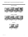
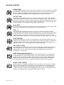
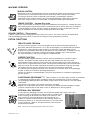
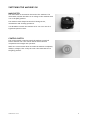
USER MANUAL
FOR
SINGLE CHAMBER
DOUBLE CHAMBERS
SPECIALS
Ensure that you have the following information on hand for explanations and/or comments.
MACHINE CODES / SPECIFICATIONS
Machine type:…………………………………..
Number:………………………………………
Single seal
Seal 1-2
Digital standard
Display info
Cut-off seal
Bi-active seal
Digital sensor
Code 1 ………
Double seal
Soft-air
Gas flushing
Code 2 ………
Henkelman BV - P.O. Box 2117 - 5202 CC ’s-Hertogenbosch
Telephone: +31 (0)73 – 621 36 71 - Telefax: +31 (0)73 – 622 13 18
E-mail: [email protected] - Internet: www.henkelman.com
User manual single/double-chambers-Eng/rev01
CONTENTS
Contents
2
Range single chambers / double chambers and specials
3
Introduction – machine codes / specifications
4
The most important components in the machine
5
Installation instructions
· Safety and installation
· Installation and safe usage of a gassing system
6
6
6
Machine versions
7
Switching the machine on
9
Starting the machine
10
Description of the control panel
11
Description of panel display – Individual cycles
13
Programming values with the control panel
· Manual (re)programming - digital time control
· Manual (re)programming - sensor control
· Automatic (re)programming – digital time control
· Automatic (re)programming - sensor control
15
15
16
17
18
Operational control of the machine
19
Maintenance
·
·
·
·
·
20
20
21
22
23
25
of the machine
General maintenance
Maintenance schedule – Oil filling procedure
Condioning Programme “C”
Oil types – maintenance of the seal bar
Dimensions and specifications of service components for maintenance
Electrical diagrams
26
Pneumatic diagrams
29
Important comments on special versions & applications
· Machine with gas flushing system
· Packaging liquid products
31
Problem solving
32
Liability – Guarantee
34
Machine specifications
35
Manufacturer’s default settings
37
This manual relates to the Henkelman Floor models and double chamber models. The general instructions apply to
these categories of models. Henkelman BV cannot be held liable for any damage caused by deviating machine
specifications.
This manual has been created with the utmost care. Henkelman BV will not accept any liability for any errors in this
manual and/or the consequences of the incorrect interpretation of this manual.
Henkelman BV is not liable for damages and/or problems caused by the use of components not supplied by
Henkelman BV
If this manual does not contain instructions for certain repairs, adjustments or maintenance, please contact your
dealer or Henkelman B.V.
Henkelman BV reserves the right to change specifications and/or components without prior notice.
All rights reserved. Nothing in this publication may be copied or made public by means of photocopies, printing or
any manner whatsoever without prior permission from Henkelman BV
HENKELMAN user manual
2
SUPERIOUR QUALITY IN MAP/VACUUM PACKAGING TECHNOLOGY
SINGLE CHAMBER
H300 AA
H300
H400AA
H400 RVS
DOUBLE CHAMBER
H500
H700
H600
H800
SPECIALS
H325
HENKELMAN user manual
H350
3
INTRODUCTION
Henkelman is a name that stands for quality in the vacuum / MAP (gassing) packaging technology field.
This quality is a product of our vision and the associated, tried-and-tested approach. Specialist knowledge
of the market and the product guarantees solid machines that meet high quality standards and provide
optimum operational safety and convenience.
The aim of Vacuum / MAP packaging technology is to add significant product value by means of extended
product storage life, increased product hygiene or better product presentation. Using ORIGINAL
HENKELMAN packaging systems and their applications will benefit the operational efficiency, quality,
storage life and presentation of products.
The range of machines consists of a large number of models and versions that are capable of meeting
specific and individual user requirements in various sectors of industry.
The packaging systems are used in the food and non-food sectors, retail and wholesale businesses and
small and large-scale industrial production units.
All the packaging systems in this manual have the following items as standard:
w
w
Digital time control panel with 9 individually adjustable programs.
Double seal - Standard time controlled seal system with 2x 3.5 mm concaved wire.
The following options (for additional costs) are applicable to most packaging systems:
ð
ð
ð
ð
ð
ð
ð
ð
Cut-off seal – (Standard time controlled seal system with
1x 3,5 mm concaved seal wire and 1 x cut-off wire Ø1.1 mm)
8 mm seal – (Standard time controlled seal system with 1x 8 mm flat seal wire)
Seal 1-2 – (Advanced time controlled seal system with separate adjustable seal and cut-off time)
1x 3.5 mm concaved seal wire and 1 x cut-off wire Ø1.1 mm
Bi-active seal – Time controlled double-sided seals system with 2 flat seal threads 1 x 5 mm and 1 x 8 mm
Gas flushing system– Injection of gas for MAP packaging applications
Sensor control – Digital control panel with pressure sensor
Soft-air – Controlled decompression system
Liquid insert plate – additional component for the packaging of liquid products.
(All versions are described in detail on pages 7 and 8)
The complete machine specifications are provided in the Henkelman catalogue. If you have any further
questions or comments, please contact your supplier or Henkelman BV for further information.
If you have any questions or comments regarding the operation or application of your machine, ensure
that you have the information printed on the front of this manual on hand for explanations or comments.
HENKELMAN user manual
4
THE MOST IMPORTANT COMPONENTS IN THE MACHINE
Seal bar
Contra-bar / Silicon profile
Lid seal
Lid lock
Vacuum meter
Controle switch
Machine plate
Control panel
Main switch
Oil filling plug
Oil sight glass
Oil drainage plug
HENKELMAN user manual
5
INSTALLATION INSTRUCTIONS
Safety and installation
q
Never package products under vacuum that may be damaged during the packaging process. Live goods
may never be vacuum packed!
q
The machine must be placed on a stable and level surface. A level surface is required to allow the
machine to be closed effectively.
q
The direct vicinity of the machine must provide sufficient ventilation space. Machines may not,
therefore, be built in and there must be a gap of at least 5 cm around the machine.
q
Check that the voltage stated on the type plate (on the back of the machine) corresponds with the
mains voltage. If you have any doubt, contact your supplier or Henkelman BV
q
If you are installing a three-phase version, check the direction of the pump.
F
The earth connection (green/yellow) of the machine must be connected correctly. Consult your
installer if you have any doubt.
q
Check the oil level of the vacuum pump.
q
The ambient temperature around the machine must be between 5° and 30°C. If this is not the case,
the type of oil used must be changed. For the correct type of oil refer to page 36 or consult your
supplier/Henkelman BV
q
Prevent the machine from tilting during installation; this may damage the vacuum pump.
Installation and safe usage of a gas flush system
F
NEVER use flammable gasses or gas mixtures containing oxygen. If these gas mixtures are used
there is a risk of the vacuum pump and/or machine exploding. The Guarantee will lapse and
Henkelman will not be held liable in any way whatsoever if accidents and/or damage result from
the use of the gasses stated.
q
The gas bottles must always be secured correctly. If the gas function and/or the machine are not in
use, the gas bottle must be closed at the main valve. This will prevent unnecessary leakage.
q
If the machine is fitted with a gas flush system, the pressure on the pressure-reducing valve of the gas
bottle may never be higher than 1 atmosphere/1 ATO. Higher pressure will damage the machine.
Consult your gas supplier for more information on the use and installation of gas bottles. Some models
are fitted with a connection for external seal pressure. This will be discussed on pages 8 and 36.
HENKELMAN user manual
6
MACHINE VERSIONS
DOUBLE SEAL
The vacuum bag is sealed with two 3.5 mm concaved wires. The wires used have a rounded
concaved shape. This shape ensures that moisture and dirt on the seal seam is pushed to
the side, closing the packaging cleanly and completely. Two seal wires provide extra
security against rough handling of the packaging during transport and storage.
CUT-OFF SEAL
The vacuum bag is sealed with two wires. The inner seal wire is 3.5 mm wide and has a
rounded concaved shape, and the outer seal wire has a diameter of Ø 1.1 mm. The outer
wire has two functions: this wire creates a narrow seal, and the remaining flap can be torn
off manually due to the fact that the wire almost completely burns through the bag. This
provides optimum product hygiene during transport and storage.
8 mm SEAL
The vacuum bag is sealed with a single flat seal wire, 8 mm wide. This seal system is used
especially for packaging in which presentation is an important factor.
SEAL 1-2
The vacuum bag is sealed with two wires. One wire is 3.5 mm wide with a rounded
concaved shape, and the other wire has a diameter of Ø 1.1 mm. The function of SEAL 1-2
is the same as the CUT-OFF but provides the option to control the wires separately. This
makes it possible to activate the cut-off wire for longer time than the seal wire. This
modification makes it possible to seal and cut-off almost any type of bag, e.g. shrink bags.
BI-ACTIVE SEAL
Bi-active seal has a seal wire both on top and bottom. This principle enables seals to be
produced from the bottom and the top simultaneously, with the aim being to produce the
optimum amount of heat in the vacuum bag. This seal system is applied to bags with a
thickness of 200+ mu, or, for example, laminated aluminium bags.
GAS FLUSH SYSTEM
A gas flush system provides the option to fill the vacuum bag with a quantity of gas after
the termination of the vacuum cycle. This option is frequently used for vulnerable or
fragile products or if the gas provides the product with added value (e.g. product
presentation or storage life).
SOFT-AIR (slow decompression)
Soft-air is a system that the chamber can be slowly decompressed for a programmable
period subsequent to vacuuming and sealing. The vacuum chamber is decompressed so
slowly that the vacuum bag can shape itself around the product without damaging the
product or the vacuum bag. Soft-air is used primarily for the packaging of soft and/or
vulnerable products (e.g. fish), or products with hard protrusions (e.g. spare ribs).
DIGITAL TIME CONTROL
All the machines are equipped with digital controls as standard. These controls allow the
separate programming of the time control of all sub-processes in the packaging process
(vacuum, seal, decompression and possibly gas flush and soft-air). It is also possible to
record the settings of frequently used packaging processes in one of the 9 programs. The
controls are extremely easy to comprehend and simple to operate.
HENKELMAN user manual
7
MACHINE VERSIONS
SENSOR CONTROL
With Sensor control, the packaging process is controlled by means of an extremely accurate
pressure sensor. This pressure sensor ensures that the process is finished accurately
according to pressure values, expressed in percentages, programmed in advance.
Application of the pressure sensor ensures consistent packaging results and an optimum
cycle time. Sensor control is normally used in combination with a gas flush system.
SENSOR CONTROL - Vacuum Plus time
Sensor control makes it possible to program an additional vacuum period – vacuum plus time
after reaching the programmed pressure. Vacuum plus time is used to allow the air trapped
in the packaging to escape, thereby creating an optimum vacuum. Vacuum plus time can
only be used when the vacuum sensor pressure has been set to 99%.
SENSOR CONTROL – Time control
A sensor control can also be programmed for normal time control. The sensor will then be deactivated
and the packaging process will be carried out according to the programmed cycle times.
EXTRA FUNCTIONS
SERVICE HOURS PROGRAM
The service hours program is a service program which is used for installing a number of
hours after which the panel shows “oil” in the second display, to indicate that the machine
needs service. This program is used as memory to maintain a good and stable service
program for the machine. With help of this option we can prevent that, if settled correctly,
the oil is polluted in a way that it affects the optimal condition of the vacuum pump.
For more information, contact your supplier or Henkelman BV.
SLEEPER FUNCTION
Both the standard digital and sensor controls have the possibility to activate a sleeper
function. The sleeper function ensures that the pump switches off after the period
programmed into the sleeper function (while the controls remain active) if the machine is
not in use for a significant period of time. The pump will automatically reactivate when the
machine is used. This function eliminates unnecessary noise pollution caused by the pump.
The sleeper function will only activate after the first cycle has been completed.
It is necessary for the pump to heat up for a minimum of 15 minutes prior to the packaging
in order to allow it to reach its operating temperature.
Contact you supplier or Henkelman BV if you have any questions or comments regarding this
specific option.
CONDITIONING PROGRAMME “C” (only necessary in case the sleeper function is activated)
15 min
A conditioning program has been included to limit the contamination of the oil caused by
the packaging of damp products (this means products that contain moisture, but also liquids
and sauces).
This option is only useful if the sleeper function is activated
Regular use of this option will prevent unnecessary oil changes and the possibility of pump
corrosion caused by the excess water in the oil. Read more on this on page 22.
EXTERNAL SEAL PRESSURE
1 Bar
In some specific packaging processes, the normal seal system may require extra seal
pressure in order to guarantee an effective seal. For these cases,
a hose coupling can be fitted to the back of the machine. This
hose coupling is connected directly to the seal system. It is
possible to connect compressed air to this coupling. NOTE: the
maximum pressure for an external connection is 1 ATO (see photo
of the connector). (Refer to the specifications in the machine
specifications chapter).
Photo – Connectors for the gas supply and external seal pressure
HENKELMAN user manual
8
SWITCHING THE MACHINE ON
MAIN SWITCH
The main switch is mounted on the back of the machine. The
main switch ensures that there is no voltage in the machine when
it is in the [OFF] position.
The machine must always be switch off during service,
maintenance and cleaning operations.
It is advisable to switch the machine off if it is not in use for a
significant period of time.
CONTROL SWITCH
The control switch is used to switch the machine on and off
before and after use. The control switch ensures that all
components are brought into operation.
NOTE: the control switch does not make the machine completely
dead (no voltage). This is only the case if the main switch is in
the [OFF] position.
HENKELMAN user manual
9
STARTING THE MACHINE
Pressing the control switch starts the machine
(Main switch [ON] position). As the machine starts, two codes will be displayed on the control panel.
q
The first code will indicate the machine version (configuration).
q
The second code will indicate the software version of the control.
This information is significant for the supplier if you wish to receive information on the version and the
options offered by the machine and its controls. It is also wise to have these codes, and also the machine
type and number, on hand if any problems should occur.
The above codes are purely mend as an example, and not corresponding with the actual codes of your
machine.
After displaying both the codes, the default program number will be shown, and the pump will start, the
machine is ready to use. It is advisable to allow the machine to run for 15 minutes before commencing
packaging. The oil will be heated and the pump will reach its optimum operating temperature after 15
minutes.
q
Service-indicator If the [oil] message is displayed when the
machine starts, this indicates that the programmed service period
has expired.
If this is the case, you can contact your supplier who will carry out any agreed maintenance operations.
The default setting of the service indicator is [OFF]. Your dealer can program the service period of your
machine to ensure that regular preventive maintenance is carried out. This indicator is particularly useful
as a memory jogger for required oil changes.
F
NOTE
It is still possible to use the machine if [oil] is displayed. However, we recommend making an
appointment for a service or oil change as soon as possible.
HENKELMAN user manual
10
DESCRIPTION OF THE CONTROL PANEL
The control panel has two displays with which all the functions can be programmed. The progress of the
packaging process can be monitored on these displays.
DISPLAY 1
This display indicates the number of the active program during the
programming of the process values or during the course of the packaging
process. Display [C] indicates that the machine is running through the
conditioning program (see page 22).
DISPLAY 2
This display shows the programmed values of the various functions. A value on
the right indicates the time of the function, while values on the left indicate
the pressure in the chamber. If a sensor is used, a percentage is programmed
(this percentage corresponds with the actual pressure).
0% = atmospheric pressure
99% = 10 mbar
PROG BUTTON
The correct program can be selected with this button. There is the range from
0 till 9 and “C”. Program 0 cannot be changed; this is for service and
maintenance purpose only.
REPROG BUTTON
This button is used to record or change the program settings. The program in
question must first be selected with the [PROG] button. Pressing the [REPROG]
button opens the program (the program number will flash), allowing the
correct settings to be programmed. Pushing the report button again will record
the changed values. The program number will then stop flashing.
FUNCTION SELECTION BUTTONS
These buttons are used to select the desired function (vacuum, gas, seal, softair) within a program. The function display light will switch on if the function is
active.
HENKELMAN user manual
11
COMBINATION BUTTON [+] and [ STOP VACUUM ]
Use this button to increase the function values while configuring the program.
If this button is used while the machine is in operation, the current function
will be terminated and the following function will be started.
COMBINATION BUTTON [ - ] and [ STOP ]
Use this button to decrease function values while configuring a program. The
entire program will be terminated immediately if this button is used while the
machine is in operation; regardless of what function is active at the time the
button was pressed. The result will be that the machine will decompress until
the lid opens.
CYCLE DISPLAY
These LEDs indicate the functions that are currently active during the
configuration of programs or while the machine is in operation.
VACUUM METER
The vacuum meter indicates the actual pressure in the chamber. The following
table indicates the vacuum percentages that correspond with the position of
the vacuum meter.
Vacuum meter position
0
0.2
0.3
0.4
0.5
0.6
0.7
0.8
0.9
-1.0
in %
0
20
30
40
50
60
70
80
90
99
The vacuum meter will ‘run up’ to the left during the vacuum process. During
the gas flush process, the vacuum meter will partially fall back to the right,
and it will return to its original starting position during decompression.
HENKELMAN user manual
12
DESCRIPTION OF PANEL DISPLAYS OF INDIVIDUAL SUB-PROCESSES IN THE
PACKAGING PROCESS
GENERAL
The packaging process automatically runs through the individual functions. The maximum number of
functions within the process is 6 - vacuum, vacuum plus, gas, seal, soft-air, decompression. The minimum
number of functions is 3 - vacuum, seal and decompression. The number of functions is determined by the
version of the machine (standard and optional versions). This chapter describes the displays of the
individual functions on the control panel. The functions automatically follow each other in sequence
within the entire packaging process.
The operational displays of the individual functions and the programming procedures for the configuration
and saving of individual values are described in this and the following chapter.
VACUUM FUNCTION
LED for vacuum function display
Display of vacuum time (right) or vacuum percentage (left)
The time can be programmed to a maximum of 99 seconds. In the case of sensor operation, the maximum
vacuum percentage is 99%. However, a vacuum plus time can be programmed that will switch on
automatically when 99% is reached. The vacuum plus time is an additional function that ensures the
achievement of an optimum vacuum (only available at when programmed at 99%).
The correct value for the vacuum cycle depends on the chamber volume and the machine capacity. The
vacuum meter indicates the pressure in the chamber, and this allows the time period for the creation of
the vacuum to be determined on the basis of the readings on this meter.
The programming procedures for this cycle are described in the following chapter.
GASFLUSH FUNCTION
LED on for gas function display
Display of gas time (right) or chamber pressure percentage (left)
The time of the gas flush process can be programmed to a maximum of 99 seconds. However, the
maximum time for gas flush cycle in time-controlled programs is the time it takes the vacuum meter to
return to 50% (see table on page 12). In the case of sensor operation, the minimum gas percentage is 30%
(in terms of software). However, we recommend maintaining a minimum percentage of 50%. This means
that the packaging will contain 50% gas and 50% vacuum. The minimum of 50% will guarantee good seal
quality.
Information on the use, benefits and dangers of the gassing of products will be discussed in detail on page
31.
HENKELMAN user manual
13
SEAL FUNCTION
LED on for the seal function display
Seal time function display (right)
The sealing time can be programmed to a maximum of 6 seconds. However, the time that will create an
optimum seal depends on the type of seal system and the type of packaging material. The standard seal
system with standard vacuum packaging materials requires an average seal time of 2.5 to 3.0 seconds. A
number of tests will have to be carried out on the packaging material in advance in order to determine
the seal time that will create an optimum seal. Insufficient seal time will result in an inadequate or
incomplete seal, and excessive seal time will result in seal that are burnt through.
F
NOTE
The quality of the seal depends not only on the time, but also on the condition of the seal bar.
The seal bar must undergo regular servicing – see pages 23 and 24.
SOFT-AIR FUNCTION
LED on for soft-air function display
Soft-air time function display righ)
The time of soft-air can be programmed to a maximum of 99 seconds. The most suitable time can be
determined on the basis of tests. If vulnerable and/or sharp products are being packaged, slow
decompression (soft-air) for a specific time will prevent damage to the product or packaging material.
DECOMPRESSION FUNCTION
The decompression function is displayed by means of horizontal stripes that
jump up and down.
Decompression ensures that the chamber returns to the normal pressure level (1 ATO). After
decompression, the process is complete and the packaging is finished. The lid opens automatically.
HENKELMAN user manual
14
PROGRAMMING VALUES WITH THE CONTROL PANEL
GENERAL
There are two ways to program or change the values of a program:
Manual and automatic programming. The procedures for both ways differ for digital control and sensor
control. All programming options will be explained in this chapter, step by step.
MANUAL (RE)PROGRAMMING – DIGITAL TIME CONTROL
Lid open
A.
Select the correct programme no. for reprogramming with the PROG
0–9
button
B.
Press the REPROG button to access the (re)programming function.
The programme number will start to flash.
C.
Use the function selection button to select the desired function for the (re)programming
of these (time) values. The LED for the desired function is now switched on.
D.
Use the [+] and n [-] buttons to select the desired time value of the function.
The time values will appear in the large display.
E.
Repeat steps C and D for the programming of all desired functions. It is not necessary to
run through all the functions. Steps C and D need only be carried out for the functions
that require (re)programming.
F.
Press the REPROG button to save the (re)programmed values and return to the normal
operating function. (The programme number will now stop flashing)
HENKELMAN user manual
15
MANUAL (RE)PROGRAMMING – SENSOR CONTROL (optional)
Lid open
Use the PROG 0 – 9 button to select the correct programme no. for (re)programming
A.
B.
Press the REPROG button to access the (re)programming function.
The programme number will now start to flash.
Use the function selection button to select the desired function for the
(re)programming of these (percentage) values.
The LED for the desired function is now switched on.
C.
VACUUM PLUS TIME
Pressing the function selection button once selects the percentage value of the vacuum
function. If the value 99% is selected (see step D), VACUUM PLUS TIME will be displayed
after the function selection button is pressed a second time. This time can be
programmed with the aid of step D. Pressing this button a third time will move you on
to the following step.
D.
Use the [+] and [-] buttons to select the desired (percentage or time value) of the
function. The values are shown in the large display.
E.
Repeat steps C and D for the programming of any desired sub-process. It is not
necessary to go through all the functions. Steps C and D need only be carried out for
the function that requires (re)programming.
F.
Press the REPROG button to save the (re)programmed values and return to the normal
operating function. (The programme number will stop flashing.)
NOTES FOR THE MANUAL (RE)PROGRAMMER
F
DE_ACTIVATING GAS FLUSH / SOFT-AIR CYCLE
The gas and/or soft-air cycles can also be switched off with the manual programming functions. During step D, the [-]
button must be held down until OFF appears in the display. This indicates that the function has been deactivated within
the program in question.
F
MACHINE VERSION
If the machine has not been fitted with a gas flush and/or soft-air function, it will not be possible to select this function
during step C.
HENKELMAN user manual
16
AUTOMATIC (RE)PROGRAMMABLE – DIGITAL TIME CONTROL
A.
Use the PROG 0 – 9 button to select the correct programme no. for the
(re)programming
B.
Press the REPROG button to access the (re)programming function.
The programme number will now start to flash.
Close lid
C.
When the lid is closed, the machine will automatically start operating in the first
function – creating a vacuum.
D.
The time value during the creation of a vacuum will increase while the vacuum
meter moves towards –1. To create a maximum vacuum in the packaging, the
vacuum meter must be at the – 1 position for at least 5 seconds. The STOP
VACUUM button must be pressed after this time has elapsed. The programming
function will now move automatically to the next step, while the vacuum value is
saved automatically in the programme.
E.
The time value in the gas flush function increases while the vacuum meter drops
back to 0. The STOP VACUUM button on the vacuum meter must be pressed after
the desired packaging pressure has been achieved. The programming function will
now automatically move to the next step, while the gas value is automatically saved
in the programme.
F.
The time value of the seal function can only be programmed in manual
programming. This is to prevent the seal time from being activated for too long.
This may have consequences for the seal wires and the seal bar. During this
automatic programming, the seal function will run through its manually programmed
time and then progress automatically to the next step.
G.
The time value in the soft-air function can only programmed in manual
programming. This prevents an unnecessary long soft-air time.
During this automatic programming, the soft-air function will run through its
manually programmed time and then progress automatically to the next step.
After completing the soft-air function, the machine will start decompressing.
H.
Lid opens
automatically
After the decompression phase, the lid will open automatically and all values will be
saved in the programme in question. The programme number will stop flashing).
NOTES REGARDING AUTOMATIC (RE)PROGRAMMING
F
SWITCHING OFF THE GAS FLUSH / SOFT-AIR CYCLE
The gas flush function and/or soft-air function can only be switched off with the manual programming functions. See
manual programming on pages 15 and 16.
F
MACHINE VERSION
If the machine is not fitted with a gas and/or soft-air function, these functions will be skipped automatically during the
automatic (re)programming.
HENKELMAN user manual
17
AUTOMATIC (RE)PROGRAMMING – SENSOR CONTROL
A.
Use the PROG 0 – 9 button to select the correct programme no. for (re)programming
B.
Press the REPROG button to access the (re)programming function.
The programme number will start to flash.
C.
Close lid
When the lid is closed, the machine will automatically start operating in the first
function – creating a vacuum.
The percentual pressure value during the creation of the vacuum will run to 99 and
then automatically switch to VACUUM PLUS TIME. To achieve maximum vacuum in
the packaging, the vacuum meter must have been at the – 0.1 position for at least 5
seconds. After the desired period of VACUUM PLUS, the STOP VACUUM button
must be pressed. The programming function will then move automatically to the
following step, while the vacuum value (percentage and VACUUM PLUS) is
automatically saved in the programme.
D.
See information on VACUUM PLUS – page 8.
E.
The percentual pressure value in the gassing function increases while the vacuum
meter drops back to 0. The STOP VACUUM button must be pressed when the desired
packaging pressure has been reached on the vacuum meter. The programming
function now moves automatically to the following step, while the gassing value is
saved automatically in the programme.
F.
The time value of the seal function can only be programmed in the manualprogramming mode. This is to prevent the seal time from being activated for too long,
which could have consequences for the seal threads and seal bar. During this
automated programming, the seal function runs through its manually programmed
duration and then changes automatically to the following phase.
The time value in the soft-air function can only programmed in manual programming.
This prevents an unnecessary long soft-air time.
During this automatic programming, the soft-air function will run through its manually
programmed time and then progress automatically to the next step.
After completing the soft-air function, the machine will start decompressing.
G.
Lid opens
automatically
After the decompression phase, the lid will open automatically and all values will be
saved in the programme in question. The programme number will stop flashing.
NOTES REGARDING AUTOMATIC (RE)PROGRAMMING
F
SWITCHING OFF THE GAS FLUSH / SOFT-AIR CYCLE
The gas flush function and/or soft-air function can only be switched off with the manual programming functions. See
manual programming on pages 15 and 16.
F
MACHINE VERSION
If the machine is not fitted with a gas and/or soft-air function, these functions will be skipped automatically during the
automatic (re)programming.
HENKELMAN user manual
18
OPERATIONAL CONTROL OF THE MACHINE
START PROGRAMME
1. Switch the machine on by means of the main switch and/or control switch.
2. Fill the vacuum bag with the product. Select a size of bag that the product will fit into easily, but
that is also not too big. Ensure that conditions are hygienic during this process. The packaging
material, product and hands must be clean and, if possible, dry.
3. Place the vacuum bag in the machine. The open side must be laid over the seal bar. However, the
bag may not protrude outside the chamber. If the product is much lower than the silicon holder, it is
recommended to use the filler plates supplied with the machine. This will make the process easier
and shorten the cycle time.
4. The vacuum bag must be laid over the seal bar without creases.
5. If a gas flush system is used, the opening of the vacuum bag must be
laid over the gas pipes.
6. Use the [PROG] button to select the desired program for the packaging
process. Refer to the previous chapter for an explanation of the
configuration of the desired programs, and refer to page 36 for the
manufacturer’s default programs.
7. Close the lid, and the machine will start the entire program by
automatically running through all the functions. The lid will open
automatically after the final function “decompression”.
8. If desired, the process can be interrupted either partially or completely by
respectively pressing the [VACUUM STOP] button or [STOP] button. The
[VACUUM STOP] button interrupts the vacuum process and changes
automatically to the next phase. The [STOP] button interrupts the entire
process and goes directly to the decompression phase.
9. The packaged product can be removed from the machine.
10. If the machine is fitted with a cut-off seal system, the excess foil can be
torn off.
F
NOTES
- Correct size and good quality vacuum bag
- Maximum 75% product filling in vacuum bag
HENKELMAN user manual
19
MAINTENANCE OF THE MACHINE
GENERAL MAINTENANCE
Regular and complete maintenance is necessary for the prevention of disruptions and ensuring the
optimum life span of the machine.
We recommend that you arrange the maintenance intervals in consultation with the supplier by means of
a maintenance contract. If the machine is used intensively (more than 4 hours per day), we recommend a
half-yearly service. In other cases, a single complete annual service will be sufficient. (This depends on
location and application).
However, there are minor maintenance operations that must be carried out more frequently and that can
be performed by the user. A maintenance schedule and these maintenance operations are provided in this
chapter. The following important comments must be taken into account before you start any
maintenance.
IMPORTANT BEFORE AND DURING MAINTENANCE OPERATIONS
F Prior to performing any maintenance, ensure that the machine is completely switched off by the
main switch.
F If the machine is not functioning correctly, the main switch must be switched off immediately in
order to ensure that the machine is completely deactivated.
F If the maintenance schedule described in this chapter is not adhered to in its entirety, neither the
supplier nor Henkelman BV can be held liable for possible disruptions or defects.
F Always consult the supplier or Henkelman BV if you have any questions or if there is any confusion
regarding maintenance.
F Major service must be carried out by a recognized supplier.
F The machines are designed for a maximum of 8 hours use per day. If this period has clearly been
exceeded, the supplier and manufacturer cannot be held liable for any disruptions or defects.
F High pressure cleaning of the machine is not permitted. High pressure cleaning may cause
significant damage to the electronic and other components of the machine.
F Water may never be allowed to enter the extraction outlet of the chamber or the blow off outlet
of the pump. This will irreparably damage the pump.
F The machine may never be tilted during transportation. This may damage the vacuum pump.
HENKELMAN user manual
20
MAINTENANCE SCHEDULE
DAILY:
Clean the vacuum chamber, lid, and possibly the housing after use with a damp cloth.
Never clean the machine with a high-pressure hose. This may cause defects in
machine components. If the machine has been fitted with a transparent lid, never
clean it with a synthetic cleaner.
WEEKLY:
Check the oil level, paying close attention to quantity and clarity. If the oil is
insufficient or extremely cloudy, the pump must be filled up with the correct type of
oil (see page 21-23 for instructions). Be sure to check whether the oil filter needs
changing (see photo of oil filling procedure).
Check the seal bar for damage. Replace the seal wire and/or teflon tape if necessary
(see page 23-24 for instructions). Pay close attention to the quality of the contra
rubber and contra bar and replace if necessary.
Check the lid seal and replace it if it has been damaged or pulled out. Ensure that
exactly the right length is cut. (The ends must meet precisely) No opening may be
created through which air in the chamber can flow. See correct length on page 24.
HALF YEARLY:
Oil must be replaced a minimum of once every six months. Check the oil exhaust filter
for counter pressure. Consult your supplier for more information.
MAINTENANCE – OIL FILLING PROCEDURE
Depending on the model, the oil sight glass and oil-filling opening are on the back or the right of the
machine.
300-500 and 700 types
600-800 types
DRAINING OIL
If the oil check reveals that the oil is either white or cloudy, it must be replaced. Before the oil is
drained, the machine must first be warmed up in order to make the oil thinner and better able to absorb
the dirt. The conditioning program [C] can be used for this (see following page).
After the oil has been heated, the drainage plug is removed (note: it may be hot!). Ensure that as much of
the dirt as possible is removed along with the oil. Replace the plug after drainage is completed.
OIL FILLING
The oil-filling plug is unscrewed with an open-end spanner. This is the plug above the
sight glass. The pump can now be filled up with oil. Ensure that filling is carried out
in small amounts, poured in at short intervals. The oil level may not rise more than 2
mm above the gauge line (80%). It is better to top up too little than too much.
HENKELMAN user manual
21
CONDITIONING PROGRAMME “C”. (only necessary in case the sleeper function is activated)
A conditioning program has been included to limit the contamination of the oil caused by the packaging of
damp products (this means products that contain moisture, but also liquids and sauces).
This option is only necessary if the sleeper function is activated.
Regular use of this option will prevent unnecessary oil changes and the possibility of pump corrosion
caused by the excess water in the oil.
Method:
Run through the various program numbers with the aid of the “PROG” button. Stop when “C”
Appears in the first display. The machine is now ready for the “Conditioning program “.
Closing the lid will start the program.
The cycle will alternate between creating a vacuum and decompressing for a
period of 15 minutes.
These 15 minutes will be counted down to zero in the second display.
During this cycle, an inspection light will run in the first display.
The program will terminate after 15 minutes.
The inspection light will fade.
‘C’ will once again be displayed in the first display.
To leave the “Conditioning program”, use the ‘PROG’ button to select another program.
We recommend that you carry this procedure out at least once per week, and twice per week if you are
packaging products that contain moisture.
HENKELMAN user manual
22
OIL TYPES
Take note of the type of oil used for the pump. Another type of oil may damage the pump. The following
types of oil can be used in the machines.
Machine type
300 Types / 500
300 Types / 500
60 Hz.
400 Types / 600 / 700
800
Pump type
Oil quantity
063-122
063-132
100-132
302-132
1 litres
2 litres
2 litres
6.5 litres
Oil type
Viscosity VG
Viscosity VG
Viscosity VG
Viscosity VG
100
100
100
100
Examples of supplier’s brands of these types of oil are Shell Vitrea 100, Aral Motanol GM 100, BP Energol
CS 100 or Texaco Regal R+ O 100. The quantities of oil in the table are appropriate for the relevant
pumps. The quantities of other types may differ. If the machine is used beyond normal ambient
temperature specifications, see page 31 or consult your supplier for the correct type of oil.
MAINTAINING THE SEAL BAR
The seal quality of the packaging is entirely dependent on the maintenance of the seal bar and the contra
bar. The seal wires and teflon tape must be in good condition in order to guarantee a good seal. These
components must be maintained regularly.
The seal bar and contra bar must be cleaned with a moist cloth on a daily basis. There may be no
imperfections on the top of the seal bar and the silicon rubber in the contra bar must be in good condition
and replaced regularly.
REPLACING THE SEAL WIRES AND TEFLON TAPE
è Remove the seal bar from the machine by unscrewing the locking screws on
the side of the bar or the screw if the bar is in the lid.
è Teflon tape is removed from the seal bar and the seal wires can now be
removed by unscrewing the clamping plates.
è Check that both tension springs are present and correctly positioned before
placing the new seal wires.
è Cut a new piece of seal wire to the length of the seal bar plus
approximately 15 cm. If it is a double seal system or cot-off seal system, a
second piece of seal wire or a piece of cot-off wire will have to be cut.
è Place the wire or wires in one of the clamping plates on the side of the
seal bar and screw the clamping plates into place. Ensure that the wires
are evenly placed over the width of the bar.
è Place the seal bar with the top facing down in a bench vice and tighten the
seal wire or wires.
è The ends of the seal wires may now be inserted into another clamping
plate and the clamping plate screw may be tightened manually. Use
pliers to further tighten the threads.
HENKELMAN user manual
23
è For optimum wire tension, use the pliers as a lever.
The tighter the wires, the longer they can be used.
è Cut the excess wire off after both wires have been tightened and fixed in
place.
Cut off just under the clamping plate
è Place a new piece of teflon tape on top of the new seal wires. Rub the
Teflon tape so that the contours of the seal threads are clearly visible.
è Cut the Teflon as shown at the photo. (This is necessary because the ends
must be able to move freely if the wire expand).
è Cut the Teflon tape so the hole for fixating the seal bar into the machine is
free.
è
è
The fastons (for the electrical connection of the seal bar)
Make sure the washer is behind the electrical terminal.
The seal bar can now be put back into the machine.
POINTS OF ATTENTION WHEN REPLACNG THE LID AND CONTRA RUBBER
Lid rubber:
The length of the new lid rubber to be fitted is ascertained on the basis of the
old rubber. A lid rubber that is too short or too long may cause problems when
closing the lid.
The rubber must be placed evenly and without any tension.
The ends must be cut straight and laid tightly against each other. This will
prevent leaks.
Contra seal rubber:
In the same way, the length is ascertained on the basis of the old rubber.
Here too, the rubber must be pressed into the groove evenly and without tension in order to create a
correct seal.
HENKELMAN user manual
24
DIMENSIONS AND SPECIFICATIONS OF SERVICE COMPONENTS FOR MAINTENANCE
HENKELMAN
CODE
DESCRIPTION
MACHINE TYPES
300(A) II
0305000
Seal wire
3.5 x 0.3
0305010
Cut-off wire
Ø 1.1
0305510
Teflon tape
0320210
Lid rubber
6x8
0320228
Lid rubber
4x9
0320200
Contra rubber
17 x 8
300 AA
300 S
400 A
KL
400
LL
500
600
700
800
4 x 760 (double)
2 x 840 (cut-off)
2 x 640
2 x 950
4 x 950
4 x 610
4 x 880
4 x 710
4 x 1100
2 x 760
1 x 840
1 x 640
1 x 950
2 x 950
2 x 610
2 x 880
2 x 710
2 x 1100
2 x 570
1 x 650
1 x 550
1 x 860
2 x 860
2 x 520
2 x 800
2 x 620
2 x 1050
1 x2500
3000
3000
2450
3000
3000
4000
2 x 510
1 x 590
1 x 490
1 x 810
2 x 810
4 x 460
4 x 640
4 x 560
X
X
X
X
X
X
4 x 840
Oil filter
0939090
0939091
Oil filter
X
0939011
Oil exhaust
filter
1 x 50 Hz
0939010
Oil exhaust
filter
1 x 60 Hz
0939015
Oil exhaust
filter
0439520
Oil
1x
2x
2x
2x
2x
3x
1 litre
2 litre
2 litre
1 litre
2 litre
2 litre
6 litre
Dimensions are in millimetres. This table only includes the standard versions for machines. Consult your
supplier for the dimensions and specifications of specific versions.
MAINTENANCE OF A BI-ACTIVE SEAL MECHANISM
If the machine is fitted with a bi-active seal mechanism, the maintenance of the seal bars must be carried
out with great accuracy and precision. The seal wires on the lower and upper bars must be positioned
exactly below and above each other. We recommend that you ask your supplier to carry out this
operation.
HENKELMAN user manual
25
ELECTRICAL DIAGRAMS
We have divided the electrical diagrams into a main current and control current diagrams.
In addition, the single and double chambers have their own control current diagrams.
Single chamber control diagram (300-400 Series):
Double chamber control diagram(600-800 Series):
HENKELMAN user manual
26
Double chamber control diagram(500-700 Series):
Main current diagram for single and double chambers:
HENKELMAN user manual
27
Overview of the fuses used:
Various fuses are used in the machines described and are indicated in the relevant diagrams.
For the sake of completeness, the locations of these fuses are given again:
Depending on the type of machine and the relevant connection voltage, a circuit breaker or fuses will be
mounted at the mains voltage entry point (in the electrical connection box).
Fuses are also fitted in any transformers used (control and seal transformers).
Two fuses are fitted to the control printed circuit board.
The various mains voltages mean that an enormous range of fuses has been used. For the correct values,
we therefore refer you to the specifications for the component in question.
WARNING
è To prevent fire and/or other irreparable damage, the replacement fuses must be of the
same values and types.
HENKELMAN user manual
28
PNEUMATIC DIAGRAMS:
The pneumatic diagrams are sub-divided into the following groups:
· Single chamber with a transparent lid
· Single chamber with a closed Stainless Steel lid
· Double chamber with a aluminium casted chamber and lid with control window.
· Double chamber with a closed Stainless Steel lid.
Pneumatic diagram H300A & H300
Pneumatic diagram H300RVS & H400RVS
HENKELMAN user manual
29
PNEUMATIC DIAGRAMS – 2
Pneumatic diagram H500 & H700
Pneumatic diagram H600 series & H800
HENKELMAN user manual
30
IMPORTANT COMMENTS ON SPECIAL MACHINE VERSIONS & APPLICATIONS
MACHINE WITH GAS FLUSH SYSTEM [MAP]
A package with a complete vacuum is subject to a pressure of 1 kilogram per cm2 or 1 ATO. Some products
are too fragile, soft or sharp, which may mean that this pressure will damage the product and/or the
packaging.
A gas flush system that makes it possible to fill packaging with gas solves the problem of how to protect
these products against vacuum pressure. Gas flush also provides other benefits for specific products in
terms of storage life, presentation and handling. Contact your dealer and/or gas supplier for more
information on gas flush packaging and types of gas mixtures.
The following points are extremely important when using a gas flush system:
è NEVER USE GAS MIXTURES WITH MORE THAN 10-15% OXYGEN (O2). THIS CAN RESULT IN LETHAL
EXPLOSIONS.
è NEVER USE SEPARATE GAS BOTTLES WITH A MIXER WHEN ONE OF THE BOTTLES CONTAINS
OXYGEN. THIS CAN RESULT IN LETHAL EXPLOSIONS.
è All liability lapses and the guarantee are invalid for any accidents and/or damage resulting from
the use of oxygen.
è The maximum permitted gas pressure in the packaging is 50% (-0,5 bar on the vacuum meter). A
higher gas pressure will have a negative effect on the seal quality. If a higher gas pressure is required,
consult the supplier regarding the options for the connection of external seal pressure. Page 8.
è We recommend that you check the pressure and the quantity of gas in the gas bottle regularly and
replace the bottle if there is insufficient pressure and the gassing cycle time is too long. Ensure that
the gas bottles are secured correctly.
è Always close the main valve of the gas bottle when the machine is not in use or when the gas function
is inactive.
PACKAGING LIQUID PRODUCTS
The machines can also be used for the packaging of liquid products such as soups or sauces. The packaging
principle is the same as that used for the packaging of dry products. However, the time of the vacuum
process must be shorter than the time it takes for the liquid product to boil.
The boiling points of liquids are reached at lower pressure and higher temperatures. Tests will have to be
carried out in order to ascertain the time that it takes for the product to boil.
The automatic programming (see pages 17-18) has a convenient configuration procedure for this. When
the product reaches its boiling point, the STOP VACUUM button is pressed and the correct value (time or
percentage) is immediately saved in the program.
The following table of the relationship between pressure and water temperature will serve as an
indication:
Vacuum pressure [mbar]
1000
800
600
400
200
100
50
20
10
5
2
Temperature [°C]
100
94
86
76
60
45
33
18
7
-2
-13
HENKELMAN user manual
31
PROBLEM SOLVING - 1
PROBLEM
The machine does not
operate.
CAUSE
·
SOLUTION
The plug has not been inserted
into the wall socket.
The mains voltage fuse is (are)
defective.
The circuit breaker in the
electricity connection box is
activated.
The contact block of the power
switch has come loose
·
·
Check it and secure it again if
necessary
·
·
The fuse on the printed circuit
board has blown.
The fuse in the control
transformer has blown
The lid switch is defective.
·
There is an internal PCB defect. ·
Remove the front panel and fit a
new fuse.
Check it and replace it if
necessary.
The lid switch must be set in the
correct manner.
Consult your dealer.
The lid does not open
automatically.
·
The gas damper or spring is
defective.
·
Consult your dealer.
There is insufficient
vacuum.
·
The vacuum value has not been
programmed long enough.
There is insufficient oil in the
vacuum pump.
·
Increase the vacuum time.
·
Check the oil level and top up if
necessary. The correct type of oil
is necessary for the effective
operation of the vacuum pump.
Lay the vacuum bag a little nearer
to the seal bar.
·
·
·
The machine is not
operating but the
operation light is lit.
·
·
·
·
·
·
The suction hole at the rear of
the vacuum chamber has been
partially block by the vacuum
bag.
The lid rubber is worn out.
The oil is dirty.
·
·
·
·
·
·
·
Insert the plug into the wall
socket.
Replace the fuse(s) (take note of
the correct value)
Reset the circuit breaker.
Replace the lid rubber.
Replace the oil with the prescribed
oil type
.
Machine creates
vacuum too slowly.
·
·
HENKELMAN user manual
The intake filter of the pump is
blocked.
The oil exhaust filter is blocked
·
Consult your dealer.
·
Consult your dealer.
32
PROBLEM SOLVING - 2
PROBLEM
The vacuum bag has not
been sealed correctly.
CAUSE
·
The vacuum bag was not placed
over the seal bar correctly.
·
The seal time has been set too
long or too short.
The silicon rubber in the contra
bar is damaged and/or worn.
The Teflon tape has been
damaged.
The opening of the vacuum bag
has been contaminated.
There has been gas flushed too
far back
·
·
·
·
The gas percentage in
the vacuum bag is
insufficient (optional).
·
·
·
·
The gas bottle is empty or
nearly empty.
The gas bottle is still closed.
The gas flushing value has been
set too long or too short.
The gas pressure has been set
incorrectly.
SOLUTION
·
Place the vacuum bag tightly and
smoothly over the seal bar.
Ensure that the opening of the
bag always stays inside the
vacuum chamber.
·
·
Set the seal time longer or
shorter.
Replace the silicon rubber.
·
Replace the Teflon tape.
·
Clean the opening of the vacuum
bag.
Check this by switching the gas
function off.
·
·
Replace the gas bottle.
·
Ascertain whether the gas bottle
valve is closed. If so, open it.
·
Increase or decrease the gas flush
value.
Check the pressure gauge to
ensure that the gas pressure has
been set to 1 atmosphere.
·
WARNING! The pressure of the gas
mixture may never be higher than 1
atmosphere.
WARNING
è To prevent fire and/or other irreparable damage, the values and types of the replacement
fuses must correspond with the originals.
HENKELMAN user manual
33
LIABILITY
1. We exclude all responsibility inasmuch it is not proviced for by law.
2. Our liability will never exceed the total amount of the particular order.
3. Subject to the generally accepted rules of law concerning public order and good faith, we are not
obliged to compensate for damages of any nature, direct or indirect, including operational damages
to movable and immovable property or damage to any persons including the contracting party or any
third party.
4. Under any circumstances we are not responsible for damage that is caused by or is the result of
misuse of the equipment as delivered or through using said equipment for any other purpose than for
what the contracting party has purchased it.
GUARANTEE
1.
2.
3.
4.
5.
6.
In compliance with the under mentioned restrictions, we guarantee the equipment
as delivered by us for a period of 6 months. This guarantee is limited to those malfunctions occuring due to factory defects, and does not include malfunctions that
are caused by any form of wear or tear during use of the equipment or parts as
delivered.
Any parts or attachments that we have received from any third party are not
guaranteed for any period longer than the guarantee given us by said third party.
The guarantee is cancelled if the contracting party or any third party brought in by the contracting
party, uses the equipment in an incompetent manner.
The guarantee is also cancelled if the contracting party or any third party brought in by the
contracting party, makes any changes or adjustments to the equipment as delivered.
If it is necessary to replace any parts in accordance with this guarantee, than all parts replaced
become our property.
If the contracting party fails to fulfill in whole or part of any obligations in compliance with this
agreement for any period of time, then we are not bound to the guarantee as long as the situation
continues.
The term of warranty and liability are a subdivision of the general sales conditions and are available on
request.
HENKELMAN user manual
34
MACHINE SPECIFICATIONS FOR STANDARD MODELS
300
300 A
300 AA
300 S KK
Model:
Cycle period:
Double seal:
Soft-air:
Nett seal length (mm)
Final vacuum:
Vacuum pump (Busch):
Vacuum chamber:
Housing:
Lid:
Dimensions in mm,
Machine (w x l x h):
Chamber (l x h):
Ambient temperature:
Electrical,
Mains voltage:
Frequency:
Capacity:
Floor
15-40 sec.
standard
standard
1 x 590 or 2 x 500
99.95%
063 m3/u
Stainless Steel
Stainless Steel
transp. plastic
Floor
15-40 sec.
standard
option
1 x 600 of 2 x 500
99.95%
063 m3/u
Aluminium
Stainless Steel
transp. plastic
Floor
20-45 sec.
standard
option
2 x 500
99.95%
063 m3/u
Aluminium
Stainless Steel
Aluminium
Floor
15-35 sec.
standard
standard
2 x 500
99.95%
063 m3/u
Stainless Steel
Stainless Steel
Stainless Steel
680 x 680 x 1020
680 x 680 x 1020
490 x 520 x 170
490 x 520 x 170
min.5˚C,max 30˚C min.5˚C,max 30˚C
680 x 680 x 1020
490 x 520 x 210
min.5˚C,max 30˚C
680 x 680 x 1020
490 x 520 x 190
min.5˚C,max 30˚C
see type plate
see type plate
see type plate
see type plate
see type plate
see type plate
see type plate
see type plate
see type plate
see type plate
see type plate
see type plate
350 KK
400 A KL
400 LL
500
Model:
Cycle period:
Double seal:
Soft-air:
Net seal length (mm)
Final vacuum:
Vacuum pump (Busch):
Vacuum chamber:
Housing:
Lid:
Dimensions in mm,
Machine (w x l x h):
Chamber (l x h):
Ambient temperature:
Electrical,
Mains voltage:
Frequency:
Capacity:
Floor
15-40 sec.
standard
standard
2 x 320
99.95%
063 m3/u
Stainless Steel
Stainless Steel
transp. plastic
Floor
15-35 sec.
standard
option
1 x 760 1 x 475
99.95%
100 m3/u
Aluminium
Stainless Steel
Aluminium
Floor
15-40 sec.
standard
standard
2 x 805
99.95%
100 m3/u
Stainless Steel
Stainless Steel
Stainless Steel
Double chamber
15-35 sec.
standard
option
2 x 440
99.95%
063 m3/u
Aluminium
Stainless Steel
Aluminium
465 x 1050 x 1010 800 x 900 x 1050
320 x 890 x 100
760 x 515 x 210
min.5˚C,max 30˚C min.5˚C,max 30˚C
760 x 920 x 1150
455 x 830 x 190
min.5˚C,max 30˚C
880 x 1080 x 1070
470 x 570 x 210
min.5˚C,max 30˚C
see type plate
see type plate
see type plate
see type plate
see type plate
see type plate
see type plate
see type plate
see type plate
see type plate
see type plate
see type plate
600
675
700
800
Double chamber
15-40 sec.
standard
standard
2 x 620
99,95%
100 m3/u
Stainless Steel
Stainless Steel
Stainless Steel
Double chamber
15-35 sec.
standard
option
2 x 620
99,95%
160 m3/u
Stainless Steel
Stainless Steel
Stainless Steel
Double chamber
15-35 sec.
standard
option
2 x 540
99,95%
100 m3/u
Aluminium
Stainless Steel
Aluminium
Double chamber
15-40 sec.
standard
standard
2 x 840
99,95%
300 m3/u
Stainless Steel
Stainless Steel
Stainless Steel
870 x 1550 x 1180 1200 x 1550 x 1080
620 x 500 x 210
620 x 750 x 210
min.5˚C,max 30˚C min.5˚C,max 30˚C
1010 x 1280 x 1070
580 x 700 x 210
min.5˚C,max 30˚C
1200 x 2000 x 1180
840 x 830 x 210
min.5˚C,max 30˚C
see type plate
see type plate
see type plate
see type plate
see type plate
see type plate
see type plate
see type plate
see type plate
Model:
Cycle period:
Double seal:
Soft-air:
Net seal length (mm)
Final vacuum:
Vacuum pump (Busch):
Vacuum chamber:
Housing:
Lid:
Dimensions in mm,
Machine (w x l x h):
Chamber (l x h):
Ambient temperature:
Electrical,
Mains voltage:
Frequency:
Capacity:
HENKELMAN user manual
see type plate
see type plate
see type plate
35
MACHINE SPECIFICATIONS
OIL SPECIFICATIONS
Recommended oil types for deviating ambient temperatures
Ambient temperature
Recommended oil types
5-12°C
VM 068
30-40°C
VS 100 or VE 101
ELECTRICAL CONNECTION
The maximum voltage fluctuation is +/-10% of the official voltage stated on the type plate.
GAS BOTTLE CONNECTION SPECIFICATIONS
The maximum gas pressure in the machine is 1 ATO. This pressure is adjusted at the gas bottle by means
of a gas pressure distributor. The following specifications apply to the connection of the bottle to the
machine.
Machine type
300
400
500
600
700
X
x
x
x
x
Hose column: Ø 8 mm
Hose column: Ø 13 mm
800
x
EXTERNAL SEAL PRESSURE CONNECTION SPECIFICATIONS
Maximum permissible pressure
1 bar
Composition
Dry compressed air
Hose connection
Hose column Ø 6mm
NOISE LEVEL SPECIFICATION
Measured noise level for all
types
< 70 DB
WEIGHTS AND VOLUMES
Machine type
300
300 AA
400
400 A
500
600
675
700
800
Machine dimensions
L
W
H
68
68
102
68
68
102
91
74
112
91
74
112
108
89
104
87
155
118
120
155
118
127
102
104
120
200
118
Machine dimensions packed
L
w
H
87
87
130
87
87
130
108
96
140
108
96
140
126
103
132
173
98
139
173
133
138
108
146
140
218
133
138
Volume packed (m3)
0.98
0.98
1.45
1.45
1.71
2.35
3.17
2.20
4.00
Weight unpacked (kg)
142
147
251
200
210
359
535
315
657
Weight packed (kg)
200
205
317
273
293
479
660
427
855
HENKELMAN user manual
36
MANUFACTURER’S DEFAULT PROGRAMME SETTINGS
DIGITAL TIME CONTROL
Programme
0*
1
2
3
4
5
6
7
8
9
Vacuum value
Gas value
30
OFF
25
OFF
20
OFF
15
OFF
10
OFF
30
5
25
5
20
10
20
15
15
15
Seal time
2.5
2.5
2.5
2.5
2.5
2.5
2.5
2.5
2.5
2.5
3
3
3
3
3
2
2
2
2
2
Soft-air time
MANUFACTURER’S DEFAULT PROGRAMME SETTINGS
SENSOR CONTROL
Programme
0*
1
2
3
4
5
6
7
8
9
Vacuum value
Vacuum plus
time
Gas value
99
99
99
99
99
99
99
OFF
OFF
OFF
15
10
15
10
10
10
OFF
30
30
30
OFF
OFF
80
70
60
50
80
OFF
80
OFF
Seal time
2.5
2.5
2.5
2.5
2.5
2.5
2.5
2.5
2.5
2.5
3
3
2
2
2
2
2
2
2
2
6
7
8
9
Soft-air time
CLIENT PROGRAMME SETTINGS – TO BE FILLED IN
Programme
0*
Vacuum value
99
Vacuum plus
time
1
2
3
4
5
15
OFF
Gas value
2,5
Seal time
3
Soft-air time
* Programme number 0 cannot be changed
HENKELMAN user manual
37
NOTES:
HENKELMAN user manual
38