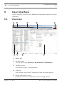
1
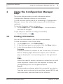
Configuration Manager 5.0
en
Installation and operation manual
Configuration Manager
5.0
Table of Contents | en
3
Table of contents
1
Using the Configuration Manager help
5
1.1
Finding information
5
1.2
Printing the Help
6
2
Introduction
7
2.1
About this manual
7
2.2
Conventions in this document
7
2.3
Additional documentation
7
3
System overview
8
3.1
Functions
4
Installation and starting
11
4.1
System requirements
12
4.2
Installation
14
4.3
Starting the program
14
4.4
Removing the program
15
5
User interface
16
5.1
Overview
16
5.2
The Menu bar
17
5.2.1
The File menu
17
5.2.2
The Tools menu
18
5.2.3
The Help menu
19
5.3
Toolbar tabs
20
5.3.1
The Devices tab
20
5.3.2
The My Devices tab
20
5.3.3
The Preferences tab
21
5.4
Toolbar icons
27
5.5
The Info bar
28
5.6
The Quick indication icons
28
5.7
The Status bar
29
5.8
The View pane
29
5.9
Used icons
31
5.10
Shortcut menu
32
5.11
Blocked input fields
35
Bosch Sicherheitssysteme GmbH
8
2014.02 | V2 | DOC
4
Configuration Manager
5.0
en | Table of Contents
6
Device configuration using Configuration Wizard
37
7
Working with Configuration Manager
39
7.1
Adding devices to the system
39
7.2
Allocating devices
39
7.2.1
Allocating listed devices
39
7.2.2
Allocating unlisted devices
40
7.3
Clearing device allocations
41
7.4
Creating groups
42
7.5
Accessing the device
43
7.6
Replacing devices
44
7.7
Saving screenshots, recordings and vbd.xml databases
46
7.8
Working offline
46
7.9
System emulation
49
7.10
Notes on multiple configuration
50
7.11
Configuring the toolbar
51
7.12
Obtaining device information
52
7.13
Disabling network scan
53
7.14
Working with Video Client
53
7.14.1
Creating users and user rights
54
7.14.2
Selecting components
55
7.14.3
Specifying access rights
55
7.15
Using Table view
56
7.16
Using Device Health Monitor
59
7.17
Device configuration using the View pane
60
7.18
Mapping replay clients using iqn-Mapper
61
7.19
Working with other components
63
7.19.1
IVA / IVMD
63
7.19.2
Video Client
63
7.19.3
VRM
63
7.19.4
Bosch VMS
63
7.19.5
Monitor Wall
64
Index
65
2014.02 | V2 | DOC
Bosch Sicherheitssysteme GmbH
Configuration Manager
5.0
1
Using the Configuration Manager help | en
5
Using the Configuration Manager
help
The online Help provides you with information about
Configuration Manager directly on your screen.
To find out more about how to do something in Configuration
Manager, access the online Help using any of the following
methods.
To use the Contents, Index, or Search:
4
On the Help menu, click Online Help.... Use the buttons
and links to navigate.
To get Help on a window or dialog (if available):
4
1.1
On the toolbar, click
.
Finding information
You can find information in the Help in several ways.
To find information in the Online Help:
1.
On the Help menu, click Online Help.....
2.
If the left-hand pane is not visible, click the Show button.
3.
In the Help window, do the following:
Contents
Display the table of contents for the Online Help. Click each
book to display pages that link to topics, and click each
page to display the corresponding topic in the right-hand
pane.
Index
Search for specific words or phrases or select from a list of
index keywords. Double-click the keyword to display the
corresponding topic in the right-hand pane.
Search
Locate words or phrases within the content of your topics.
Type the word or phrase in the text field, press ENTER, and
select the topic you want from the list of topics.
Bosch Sicherheitssysteme GmbH
2014.02 | V2 | DOC
6
Configuration Manager
5.0
en | Using the Configuration Manager help
Notice!
Texts of the user interface are marked bold.
4
The arrow invites you to click on the underlined text or to
click an item in the application.
Related Topics
4
Click to display a topic with information on the application
window you currently use. This topic provides information
on the application window controls.
1.2
Printing the Help
While using the Online Help, you can print topics and
information right from the browser window.
To print a Help topic:
1.
Right-click in the right pane and select Print.
The Print dialog box opens.
2.
2014.02 | V2 | DOC
Click Print. The topic is printed to the specified printer.
Bosch Sicherheitssysteme GmbH
Configuration Manager
5.0
2
Introduction
2.1
About this manual
Introduction | en
7
This manual is intended for persons responsible for configuring
and managing a CCTV system. This manual describes how to use
the Configuration Manager program.
This document assumes that the reader is familiar with both the
CCTV system and the other programs that are integrated into
the system.
2.2
Conventions in this document
In this document, the following symbols and notations are used
to draw attention to special situations:
Notice!
This symbol indicates special features and provides tips and
information for easier, more convenient use of the software.
Terms that you can find in the program, such as menu options or
commands, are written in bold.
2.3
Additional documentation
Once the Configuration Manager program has been installed,
this document is also available as online Help within the
program.
Documentation for Bosch Security System products can be
found as follows:
4
www.boschsecurity.com > select your region and your
country > select Product Catalog > start a search for your
product > select the product in the search results to show
the existing documents.
Bosch Sicherheitssysteme GmbH
2014.02 | V2 | DOC
8
3
Configuration Manager
5.0
en | System overview
System overview
Configuration Manager program is used to configure all IP
devices and components in your CCTV network. With
Configuration Manager you have access to all devices and
software components.
The program offers also a configuration wizard for quick basic
configuration of devices. However, you can also carry out the
further configuration with the normal user interface.
3.1
Functions
Configuration Manager provides the following functions (the
availability of these depends on the environment in which the
program is used):
–
Network Scan
The network scan is performed automatically every time
Configuration Manager starts, and is repeated at regular
intervals.
This function automatically detects all compatible devices
present in a network, such as cameras or video senders,
video receivers or VRM. The status of a device is also
queried in each scan and then indicated by the icons in
front of the devices.
–
Device information and configuration
Comparable with the Web browser view, Configuration
Manager shows the current configuration for each device
and allows you to change the settings.
–
Device system integration
You use the Device allocator in Configuration Manager to
make devices accessible for use with Video Client.
–
Configuration Wizard
A Configuration Wizard helps you to configure all devices
for basic operation in just a few steps, even for extensive
systems.
2014.02 | V2 | DOC
Bosch Sicherheitssysteme GmbH
Configuration Manager
5.0
–
System overview | en
9
Multiple configuration
You can use Configuration Manager to make individual
settings for multiple devices simultaneously (for example,
time settings), allowing you to configure large systems
more quickly.
–
Simpler access to devices
The Screenshot Scan function gives an overview of all the
cameras that provide video data. The screenshots can be
used to identify the camera and device, and give you direct
access to said camera or device.
–
Table View
This allows you to compile specific parameter settings for
selected devices. This provides you with a quick overview
of the settings that are of interest to you and allows you to
export this information for archiving at the push of a
button.
–
Device Health Monitor
This provides you with a quick overview of the status of
selected devices, such as the encoder load and type of
network connection.
–
Work Offline
Configuration Manager allows you to make settings for
selected devices offline. When in operation, the
configuration data of the devices is transferred to your
computer where it can be edited offline.
This functionality can also be used to back up the
configuration data of the devices locally. If, for example, a
device needs to be replaced by another of the same type,
this data can then be transferred to the new device.
This functionality is extended with the Replacement
command. Replaced devices are detected and automatic
configuration is possible thanks to the saved data.
Bosch Sicherheitssysteme GmbH
2014.02 | V2 | DOC
10
en | System overview
–
Configuration Manager
5.0
System emulation
The complete system configuration can be saved as a
system image and emulated using a different Configuration
Manager application. This function helps you to isolate
problems without having to access the actual system.
–
Access to license management
Firmware modules requiring a license, such as IVA
(Intelligent Video Analysis), are set up using Configuration
Manager.
2014.02 | V2 | DOC
Bosch Sicherheitssysteme GmbH
Configuration Manager
5.0
4
Installation and starting | en
11
Installation and starting
Configuration Manager is automatically part of the installation
for all video IP devices from Bosch that require Configuration
Manager for configuration purposes. Furthermore, you can also
use Configuration Manager to simplify the configuration in a
CCTV system with many similar video senders.
Bosch Sicherheitssysteme GmbH
2014.02 | V2 | DOC
12
4.1
Configuration Manager
5.0
en | Installation and starting
System requirements
Operating system
–
Windows XP SP3 (32 bit), .NET
–
Windows 7 SP1 (32 bit, 64 bit in
Framework 3.5 required
32 bit emulation mode), .NET
Framework 3.5 required
–
Windows 8 (32 bit, 64 bit in 32 bit
emulation mode), .NET Framework
3.5 required
Supported graphic NVIDIA Quadro 600
card
NVIDIA Quadro 2000
NVIDIA Quadro 5000
NVIDIA Quadro FX 580
NVIDIA Quadro FX 1400
NVIDIA Quadro FX 1500
NVIDIA Quadro FX 1700
NVIDIA Quadro FX 1800
NVIDIA Quadro FX 3500
NVIDIA Quadro FX 3700
NVIDIA Quadro FX 3800
NVIDIA Quadro FX 4000
NVIDIA Quadro FX 4600
NVIDIA Quadro FX 4700
NVIDIA Quadro FX 4800
NVIDIA Quadro Fermi 2000
NVIDIA Quadro Fermi 4000
NVIDIA NVS 295
NVIDIA NVS 440
NVIDIA NVS 450
NVIDIA GT 520
ATI FirePro V2460
ATI FirePro V3700
ATI FirePro V3800
ATI FirePro V3900
2014.02 | V2 | DOC
Bosch Sicherheitssysteme GmbH
Configuration Manager
5.0
Installation and starting | en
13
ATI FirePro V4800
ATI FirePro V4900
ATI FirePro V5700
ATI FirePro V5800
ATI FirePro V5900
ATI FirePro V7900
ATI FirePro V8800
ATI FireGL V5600
ATI FirePro V7200
Graphic cards that are not listed here
must be at least fully compatible to
DirectX 9.
Onboard graphic
All with first generation of Intel Core i-
adapter
series.
Sound card
Recommended
Network adapter
100 Mbps
Notice!
All Microsoft updates and hotfixes must be installed on target
PCs. Graphic card drivers must also have the latest officially
released version.
Bosch Sicherheitssysteme GmbH
2014.02 | V2 | DOC
14
4.2
Configuration Manager
5.0
en | Installation and starting
Installation
You can install Configuration Manager on as many computers
running Microsoft Windows as you wish.
To install Configuration Manager:
1.
Close all other applications before beginning the
installation.
2.
Download the software package.
3.
Select the extraction directory and double-click
Setup_ConfigManager.exe.
The Configuration Manager wizard dialog box is displayed.
4.
On the Welcome dialog box, click Next.
5.
In the Select components to install: list, select the
respective tools, then click Next.
6.
In the Choose Install Location dialog box, select the
destination folder, then click Install.
The installation process starts.
Note: We recommend using the default destination folder.
7.
4.3
Click Finish.
Starting the program
After successful installation, you will find the following icon on
your desktop:
To start the program:
4
Double click this icon.
or
4
On the Start menu, click Configuration Manager.
Note:
Several video IP devices from Bosch enable you to start
Configuration Manager directly within the relevant program.
2014.02 | V2 | DOC
Bosch Sicherheitssysteme GmbH
Configuration Manager
5.0
Installation and starting | en
15
Operation of Configuration Manager varies according to the
context in which it is being used. In some cases, it is merely a
tool that enables you to configure video IP devices from Bosch
more conveniently and more comprehensively. For certain
programs and firmware modules, however, Configuration
Manager is indispensable, as it is the only way to set these up.
4.4
Removing the program
If you no longer wish to use the program on your computer, you
can remove the program at any time.
To remove the program:
1.
Click Start, click Settings, then click Control Panel.
2.
Double-click Add or Remove Programs.
3.
Select the Configuration Manager entry.
4.
Click Remove.
Bosch Sicherheitssysteme GmbH
2014.02 | V2 | DOC
16
5
Configuration Manager
5.0
en | User interface
User interface
In this section, you will find detailed information about the user
interface.
5.1
Overview
2
1
6
7
3
4
8
1
Menu bar
2
Toolbar tabs
5
9
For quick access (Devices, My Devices, Preferences)
3
Toolbar icons
For quick access (configurable).
4
Info bar
With name, type and IP address of the selected device.
5
Quick indication icons
Displays CPU load, network and recording status.
2014.02 | V2 | DOC
Bosch Sicherheitssysteme GmbH
Configuration Manager
5.0
User interface | en
6
Device tree structure with filter option.
7
Additional functions, for example, Refresh
8
Status bar
9
View pane
17
Depending on the toolbar tab selected, this window
displays different device tabs with configuration options
and information.
5.2
The Menu bar
This section contains special operational functions, tools and
help functions.
5.2.1
The File menu
To obtain the menu commands:
4
Click the File menu. The following commands are
displayed.
Connect to Server...
Connects Configuration Manager to a server. This allows you to
set up a server and configure a client/server system.
Disconnect from Server
The connection between Configuration Manager and a server is
broken.
Work Offline / Work Online
The settings for selected devices can be made offline while the
device remains in operation. For this purpose, the configuration
files of the devices are backed up locally on your computer. You
can edit the data and send it back to the devices at a later
stage.
Emulate Alien System... / Abandon Emulation
Imports the system image of an alien Configuration Manager
system.
Bosch Sicherheitssysteme GmbH
2014.02 | V2 | DOC
18
en | User interface
Configuration Manager
5.0
Close
The Configuration Manager program is closed. This also breaks
the connection between Configuration Manager and the server.
5.2.2
The Tools menu
To obtain the menu commands:
4
Click the Tools menu. The following commands are
displayed.
Configuration Wizard...
Starts the wizard for the basic configuration of devices.
Logging...
Displays the Device Communication Log dialog box.
Here, you can view the RCP+ commands that are transmitted by
Configuration Manager when connecting to devices, if you have
enabled logging.
Device Allocator...
Displays the Device Allocator dialog box. An overview of all
available devices in the network and all devices that are
allocated to the system.
Table View...
Displays the Devices Table View dialog box. A summary of
specific settings for individually selected devices.
Screenshot Scan...
Displays a window in which a screenshot for each of the
connected cameras is displayed. If you right-click a screenshots,
the commands are displayed relevant for the device.
Device Health Monitor...
Displays the Device Health Monitor dialog box, which provides
a quick overview of the status of selected devices.
Save System Image
Saves the image of the currentConfiguration Manager system for
emulation on a different PC.
2014.02 | V2 | DOC
Bosch Sicherheitssysteme GmbH
Configuration Manager
5.0
User interface | en
19
iqn-Mapper...
Displays the iqn-Mapper dialog box, in which you can map
replay clients to NetApp iSCSI systems.
Others
Other software components can be started directly.
The prerequisite for this is that the relevant program is installed
on the same PC.
5.2.3
The Help menu
To obtain the menu commands:
4
Click the Help menu. The following commands are
displayed.
Online Help...
Displays the Configuration Manager online Help.
Online Help VRM...
Displays the Video Recording Manager online Help.
About...
Displays the About Configuration Manager dialog box,
containing information on, for example, the software
components installed on this PC and the software version
numbers of the installed components.
Bosch Sicherheitssysteme GmbH
2014.02 | V2 | DOC
20
en | User interface
5.3
Configuration Manager
5.0
Toolbar tabs
The toolbar enables quick access to the most important
functions.
5.3.1
The Devices tab
This tab shows all video IP devices supported by Configuration
Manager that are detected in the network scan.
Additional Information:
–
The information about a device is shown in bold if the
device is newly detected since the last network scan.
–
The information about a device is shown in red if the device
has an IP address or a MAC address that is already used by
another device in the system. This might be the case, for
example, if several devices that have not yet been
configured are connected directly after one another.
–
Additional information about the devices can be seen if you
scroll to the right.
5.3.2
The My Devices tab
This tab shows all devices that have previously been manually
allocated to the system.
Additional Information:
–
The information about a device is shown in bold if the
device is newly detected since the last network scan.
–
The information about a device is shown in red if the device
has an IP address or a MAC address that is already used by
another device in the system. This might be the case, for
example, if several devices that have not yet been
configured are connected directly after one another.
–
Additional information about the devices can be seen if you
scroll to the right.
2014.02 | V2 | DOC
Bosch Sicherheitssysteme GmbH
Configuration Manager
5.0
5.3.3
User interface | en
21
The Preferences tab
This tab enables you to access general and application-specific
settings. Here, you can carry out a basic configuration for
Configuration Manager itself as well as for other video IP
devices from Bosch.
This tab has a tree structure with the following main folders:
–
General
–
Applications
If necessary, expand the folders to obtain subordinate items.
General folder
In this tab you make the settings that affect several programs.
Changes only become active if you click the Save icon on the
toolbar.
–
General > Directories
Specifies where screenshots, recording sequences and
vdb.xml databases should be saved. These settings are
relevant for Video Client.
–
General > Logging
Enable or disable the logging of RCP+ commands. A log file
is created for every device in the system.
You can also specify the minimum period for which you
want the log data to be saved.
–
General > Client/Server
–
Access tab > Server group
Connect to server
Enable this option if you manage your system with
VRM.
For details, refer to the separate VRM documentation.
Server IP address
Enter the IP address of the computer on which VRM
has been started.
IP address failover server 1
IP address failover server 2
Bosch Sicherheitssysteme GmbH
2014.02 | V2 | DOC
22
Configuration Manager
5.0
en | User interface
If necessary, enter the IP addresses of the failover
server computers.
–
iSCSI Media tab > iSCSI Media group
Password
Enter the password for accessing the iSCSI media, if
these are password-protected. When assigning
passwords, please note that they must be valid for the
entire system.
Applications folder
In this tab you make the settings that affect an individual
program. When leaving this page Configuration Manager asks
you whether you want to save the changes. Changes only
become active if you click the Save icon on the toolbar.
Only programs that are installed on your computer are listed
under this tab. If a program is not listed under this tab, check if
it is installed on your computer and install it if necessary.
–
Applications > Configuration Manager
This is where you can change the default settings for
Configuration Manager.
–
Access tab > Access group
Password
Assign a password here that protects access to
Configuration Manager. If you do not enter anything in
this field, the program will start without asking for a
password.
This password is only valid for the computer on which
it was defined.
–
Network Scan tab > Network Scan group
Run continuous network scan
Enable this option if the network is to be scanned at
regular intervals.
Scan interval [s]
Enter the time interval in seconds for automatic
scanning here, choosing a value between 10 and
3600 seconds (1 hour).
2014.02 | V2 | DOC
Bosch Sicherheitssysteme GmbH
Configuration Manager
5.0
User interface | en
23
Use Multicast
If you are using devices in various subnets, activate
this option. This allows all devices that belong to a
different subnet than the PC on which Configuration
Manager is installed to also be included in the network
scan. Otherwise you will have to manually add these
devices to the system.
Multicast operation requires a multicast-enabled
network that uses the UDP and the Internet Group
Management IGMP protocols.
–
Network Scan tab > IP address range group
Mode
Specify the IP address ranges and expressly permit or
prohibit the use of these addresses.
–
Video tab > Monitor group
Refresh interval
Select how often the screenshots that are shown in
the various tabs (e.g. VCA) are refreshed:
Continuous: Image is refreshed as often as possible.
0 seconds: Image is displayed once but not refreshed.
1 … 10 seconds: Image is refreshed accordingly.
Encoder
Select whether the images should be displayed in
video format (MPEG) or as constantly updated
screenshots (JPEG).
–
Repository tab > Repository group
Database folder
Select the path to the folder for offline configuration.
If you do not enter anything here, the following default
setting is used.
–
Logging tab > Device I/O group
Select whether the device communication log should
be wrtten in a file and which data it should include.
–
Appearance tab > Startup group
Restore last view
Bosch Sicherheitssysteme GmbH
2014.02 | V2 | DOC
24
Configuration Manager
5.0
en | User interface
If enabled, the view last used is displayed when
Configuration Manager is next started.
After confirmation only
If enabled, the next time you start Configuration
Manager you will be asked whether you want to
restore the last view used.
–
Appearance tab > View group
Show ONVIF devices (experimental)
If enabled, all ONVIF devices are displayed.
–
Appearance tab > Toolbar group
Main toolbar
Click Edit to adapt the toolbar.
–
Appearance tab > Database camera name group
Prefix device name to camera name
Displays the encoder device name before the camera
name in the camera list if cameras are integrated into
the system over video encoders.
–
Applications > Video Client
This is where you can change the settings of Video Client.
–
User Management tab > Management tab
Users group
Implement user administration to control access to the
Video Client program.
–
Cameras tab > Camera Order tab
Camera order group
Define which cameras are listed in Video Client and
define corresponding access rights.
–
Cameras tab > Camera Access tab
Camera access group
Specify the access rights for the cameras listed in
Video Client. Each user is assigned the highest
authorization level by default.
–
Digital Inputs tab > Digital Input Order tab
Digital input order group
2014.02 | V2 | DOC
Bosch Sicherheitssysteme GmbH
Configuration Manager
5.0
User interface | en
25
Define which digital inputs are listed in Video Client
and define corresponding access rights.
–
Digital Inputs tab > Digital Input Access
Digital input access group
Specify the access rights for the digital inputs listed in
Video Client. Each user is assigned the highest
authorization level by default.
–
Alarm Outputs tab > Output Order tab
Output order group
Define which alarm outputs are listed in Video Client
and define corresponding access rights.
–
Alarm Outputs tab > Output Access
Output access group
Specify the access rights for the alarm outputs listed in
Video Client. Each user is assigned the highest
authorization level by default.
–
Application tab > Application tab
> Workstation recording group
Path for workstation recording
Select the path to the folder to which Video Client will
export manual recordings. If you do not enter anything
here, the following default setting is used:
%current user%\My Documents\ Bosch\VideoClient
\Recording
Maximum disk usage [GB]
Define the maximum hard disk memory to be used for
manual recordings. If you do not enter anything here,
the default setting 10 is used.
Delete recordings when maximum disk usage
exceeded
Activate this option if existing recordings are to be
overwritten when the specified maximum memory
capacity has been reached.
–
Application tab > Application tab
> IntuiKey group
Bosch Sicherheitssysteme GmbH
2014.02 | V2 | DOC
26
Configuration Manager
5.0
en | User interface
Use keyboard
Select the checkbox if a Intui Keyboard is used.
COM port
If the program is operated via an IntuiKey control
panel, enter the number of the COM port here.
–
Application tab > License tab
On this page you can find information on the licensing
of camera channels in Video Client. A Video Client
installation has 16 camera channels as standard. You
can enable additional channels by purchasing a
license.
For more information, please see the Video Client
operator’s manual.
Host-ID
The host ID, which is needed to install a license for
additional camera channels for Video Client, is
displayed here.
Number of cameras
The number of enabled camera channels is displayed
here.
Add License...
Click to add a license file for additional camera
channels. The Add License File.
2014.02 | V2 | DOC
Bosch Sicherheitssysteme GmbH
Configuration Manager
5.0
5.4
User interface | en
27
Toolbar icons
The toolbar icons allow quick access to several Configuration
Manager functions.
Reload page
Reloads the page for the selected device.
Info
Displays detailed information about the selected device.
Live video
Displays the live video data from the selected device.
Logging
Displays the Device Communication Log dialog box.
Here, you can view the RCP+ commands that are transmitted by
Configuration Manager when connecting to devices, if you have
enabled logging.
Device allocator
Displays the Device Allocator dialog box. This dialog box allows
you to allocate devices to the system and build the device tree
structure.
Table view
Displays the Table View dialog box.
Save
Saves any settings that have been configured for the selected
device.
Bosch Sicherheitssysteme GmbH
2014.02 | V2 | DOC
28
5.5
Configuration Manager
5.0
en | User interface
The Info bar
When one of the Devices or My Devices tabs is selected, an info
bar is displayed above the View pane. This info bar provides you
with brief information about each selected device as follows:
–
Device name
–
Device type
–
Device IP address
Note: If several devices are selected, all fields contain the entry
<Multiple>
For hardware devices, you can use the icons on the right-hand
edge of the bar to display additional information.
5.6
The Quick indication icons
To display the quick indication icons:
4
Drag the pointer on the icons to view details on the
processor load, network connection and recording status:
Quick indication icon description
–
The left icon indicates the proportions of the individual
functions on the encoder load, shown as percentages. For
devices with two processors, a separate icon is shown for
each processor.
–
The icon in the middle indicates the network connection
type and the speed of the outgoing (UL = Uplink) and
incoming (DL = Downlink) data traffic.
–
The right icon indicates information on the recording
status.
–
Green: active recording
–
Red: error
–
Orange: recording scheduler active, no current
recordings
–
Gray: recording scheduler not active, no current
recordings
2014.02 | V2 | DOC
Bosch Sicherheitssysteme GmbH
Configuration Manager
5.0
5.7
User interface | en
29
The Status bar
The status bar at the bottom edge of the window shows the
following:
–
In the left section: whether or not a network scan is
currently in progress.
–
In the central section: the number of detected, visible and
selected devices.
–
In the right section: whether you are currently working
Online or Offline, and whether or not Configuration
Manager is currently connected to a server. If it is
connected to a server, the server IP address is displayed.
Otherwise the entry DB local appears here.
If you are emulating an alien system, the entry System
emulation appears here.
–
On the far right: the version number of Configuration
Manager is displayed.
5.8
The View pane
The View pane for the Devices and My Devices tabs shows a
series of subdivided tabs, the number and content of which
depend on the device selected in the list.
The tabs in the View pane can be used to make the
configuration settings that the device also provides in the Web
browser view, some of them with a slightly different
composition.
Access from Configuration Manager to the devices can be
configured when selecting the General and Unit Access tab (not
necessary for web browser).
Detailed information about the configuration options for a
device can be found in the relevant device documentation and
the online Help in the relevant Web browser view.
Bosch Sicherheitssysteme GmbH
2014.02 | V2 | DOC
30
en | User interface
Configuration Manager
5.0
Notice!
Changes only become active if you click the Save icon on the
toolbar.
2014.02 | V2 | DOC
Bosch Sicherheitssysteme GmbH
Configuration Manager
5.0
5.9
User interface | en
31
Used icons
The devices in the Devices / My Devices tabs are represented
by the following icons:
Device icons
Encoder/Decoder
Camera
Hardware recorder
Storage system
iSCSI target
Drive
VRM server
VRM failover server
VRM server for second recording stream
VRM failover server for second recording stream
Device status icons
The status of a device is represented as follows:
Device is online.
Device is offline.
Devices that are displayed dimmed are unattainable.
No communication is possible. For example, these
could be devices for which the power supply has been
interrupted.
Device is faulty.
A red icon with an exclamation point indicates devices
that are faulty.
Bosch Sicherheitssysteme GmbH
2014.02 | V2 | DOC
32
Configuration Manager
5.0
en | User interface
Device is password-protected.
Devices that are protected by a password are indicated
by a padlock until you have authenticated yourself for
the device.
Device is offline and password-protected.
This devices are displayed dimmed and indicated by a
padlock.
5.10
Shortcut menu
Right-click a device to open the shortcut menu. If you have
selected multiple devices, not all options in the shortcut menu
are enabled.
The following provides an overview of the commands:
Add to System...
(Devices tab)
Allocates the selected device to the system. Before making an
allocation, you can select a group or create a new one.
This command corresponds to the Device Allocator dialog box.
Select Group
(My Devices tab)
If several devices have been grouped, use this command to
select all devices or cameras of that group for editing.
New Device...
(My Devices tab)
Allocates a non-listed device to the system. This command is
only active if you click the area in the left pane in which no
devices are listed.
Delete
(My Devices)
Deletes the selected device from the system.
2014.02 | V2 | DOC
Bosch Sicherheitssysteme GmbH
Configuration Manager
5.0
User interface | en
33
Set Session Authentication...
(Devices tab)
If a selected device is protected by a password, you must
authenticate yourself for that device.
Configure...
Displays the respective configuration tool if installed.
Add iSCSI System... (VRM)
Displays the Add iSCSI System dialog box.
Here, you can add an iSCSI system to the VRM using the host IP
address and the SNMP IP address.
LUN Assignment... (iSCSI system)
Displays the LUN Assignment dialog box. Here, you can add
individual LUNs to the system.
File Upload
–
Firmware...
You can select the desired upload file and start the upload.
Refer to the information about firmware uploads in the
documentation for the relevant device.
You can use this command to carry out a firmware upload
for several devices at the same time. You must ensure that
all selected devices are of the same device type when you
carry out a firmware upload for several devices at the same
time.
–
SSL Certificate...
Upload an SSL certificate to the device to enable encrypted
communication with the device.
–
Decoder Logo...
The decoder logo is the image displayed by the decoder if
there is no connection to a device. You can upload your
own logo for this purpose. This must be in H.263 format.
Bosch Sicherheitssysteme GmbH
2014.02 | V2 | DOC
34
Configuration Manager
5.0
en | User interface
Settings
(Add to System... and My Devices tab)
–
Download...
Configuration data of the selected devices is saved on your
computer for offline editing.
–
Upload...
The configuration data that was edited offline is sent to the
selected device. Once the upload has been successfully
completed, the device operates according to the new
configuration data.
–
Replacement... (only in My Devices tab)
Configuration data of replaced devices is automatically
replaced with locally stored data of a device of the same
type.
Device Network Settings...
(Add to System... and My Devices tab)
You will see the Network settings dialog box.
This dialog box is used to change the IP address, subnet mask
and gateway of the selected device or activate automatic IP
assignment via DHCP.
This is only possible for devices that are not passwordprotected.
Show Live Video...
(Add to System... and My Devices tab)
A window opens, displaying the live video data from the
selected device. You are offered different display options
depending on which device you selected.
Show in Web Browser...
(Add to System... and My Devices tab)
The livepage of the Web browser view for the device is opened
in the default browser.
Show Settings in Web Browser...
The configuration page of the Web browser view for the device
is opened in the default browser.
2014.02 | V2 | DOC
Bosch Sicherheitssysteme GmbH
Configuration Manager
5.0
User interface | en
35
Device Info...
The dialog box containing device information is displayed.
Blink LED
(Add to System... and My Devices tab)
A LED on the device flashes. This allows you to check whether
there is any communication between Configuration Manager and
the device. This command also helps you to identify a device if
several devices of the same type are installed at the same
location.
Restart
(Add to System... and My Devices tab)
Initiates a reboot of the device. This is only possible for devices
that are not password-protected.
Ping
(Add to System... and My Devices tab)
Pings the selected device to confirm network communication
with the device.
5.11
Blocked input fields
It is possible that some fields are blocked for editing. The
causes for the block are indicated by different entries in the
fields.
If several devices are selected, some
settings cannot be made. The input fields
are marked with a padlock.
If a device is currently recording, some
settings cannot be modified. The input
fields are marked with a padlock. If
necessary, stop the recording.
Bosch Sicherheitssysteme GmbH
2014.02 | V2 | DOC
36
Configuration Manager
5.0
en | User interface
If there is a configuration error, individual
fields are marked accordingly.
This icon is also displayed if the device is
offline and you attempt to load or save
settings.
Input fields you are not authorized to
change are marked by a padlock and are
blocked for editing.
Some input fields cannot be edited when
you are working offline (date and time
settings).
2014.02 | V2 | DOC
Bosch Sicherheitssysteme GmbH
Configuration Manager
5.0
6
Device configuration using Configuration Wizard | en
37
Device configuration using
Configuration Wizard
Configuration Wizard helps you to configure devices in the
network quickly and conveniently for basic operation.
Using Configuration Wizard:
1.
In the Tools menu, click Configuration Wizard..., then click
Next >.
The Configuration Wizard dialog box is displayed. The
wizard guides you through the configuration process.
2.
Passwords
You have the option of assigning universal, system-wide
passwords for the three specified user groups.
If you do not wish to do this, leave the input fields empty.
The passwords for the system user accounts are mapped to
the system components.
When accessing a device, the following passwords are
used:
administrator is used for access level service
operator is used for access level user.
Also observe the authorization levels:
–
Authorization levels of Configuration Manager:
(highest / medium / lowest)
administrator / operator / live
–
Authorization levels of video devices:
(highest / medium / lowest)
service / user / live
3.
Recorder
Select whether to record locally on the devices (e.g. to an
SD card) or using a recorder.
When using a recorder, enter the relevant IP address or
select the address of a configured recorder from the list.
4.
Device Selection
All devices detected in the network are listed. Select the
devices you want to configure with the wizard.
Bosch Sicherheitssysteme GmbH
2014.02 | V2 | DOC
38
en | Device configuration using Configuration Wizard
Configuration Manager
5.0
Note: Not all devices support IP address configuration via
DHCP. If required, click Update to configure these devices
manually at a later stage.
5.
Network
Activate the Use DHCP option if all devices support DHCP
and you want to assign IP addresses automatically in this
way.
Alternatively, enter an IP address range. This must provide
sufficient IP addresses for all the devices to be configured.
6.
Date and Time
Select whether the date and time are to be taken from the
settings on your PC or from an SNTP server. If necessary,
reset the system time and date on your PC or enter the IP
address of an SNTP server.
7.
Video Quality
Specify the quality of the video data for all devices. The
relevant settings for each device are made automatically.
8.
Recording
Create a uniform recording scheduler for all devices. If no
recordings are to be scheduled, you must select Off mode
for every recording profile.
9.
Summary
A summary of the selected settings is displayed.
Click Apply to configure the devices according to the
selected settings.
2014.02 | V2 | DOC
Bosch Sicherheitssysteme GmbH
Configuration Manager
5.0
7
Working with Configuration Manager | en
39
Working with Configuration Manager
The following section offers a list of user actions for configuring
hardware and software components that can be performed
using Configuration Manager.
7.1
Adding devices to the system
You can add devices and components to the system that are
detected in the network.
To add devices to the system:
1.
On the toolbar, click the Devices tab, right-click a device in
the tree structure, then click Add to System....
The Add Device to System dialog box is displayed.
2.
Select an existing group to assign the device or leave the
field empty if you do not want to assign the device to a
group.
3.
Click OK.
See also:
–
7.2
Allocating devices, page 39
Allocating devices
Before working with Video Client, you must complete the
allocation, as the program can only access devices that have
been allocated to the system.
7.2.1
Allocating listed devices
You can allocate all devices using the Devices tab. It is also
possible to allocate devices to the system by adding them to the
My Devices tab. This simplifies configuration as you can limit
yourself to a relevant selection of available devices and clearly
arrange the allocated devices in groups.
To allocate listed devices using the Device Allocator icon:
Bosch Sicherheitssysteme GmbH
2014.02 | V2 | DOC
40
Configuration Manager
5.0
en | Working with Configuration Manager
1.
On the toolbar, click the Device Allocator
icon.
The Device Allocator dialog box is displayed.
All devices detected in the network are displayed on the
left-hand side of the dialog box, while those allocated to
the system appear on the right.
2.
Drag the unallocated devices from the left to the right-hand
side of the window.
3.
If necessary, sort the list of entries. To do this, click the
appropriate table header.
4.
Click OK.
The devices are integrated into the system.
Notice!
If it is not possible to integrate a device, a warning message
appears.
See also:
–
7.2.2
Creating groups, page 42
Allocating unlisted devices
The Device Allocator dialog box also enables you to allocate
devices to the system that were not detected during the
network scan.
Allocating an unlisted device:
1.
In the Device Allocator dialog box, right-click into the
Allocated devices area (but not on a device).
2.
Click New Device....
The Device Editor dialog box is displayed.
3.
Enter the URL (for example, the IP address with the port
number) of the device. The IP address must previously have
been set on the device.
4.
In the Type list, select <Auto detect> or select the device
type from the list of supported devices.
If you select an ISDN-compatible device, the field for the
telephone number is also activated.
2014.02 | V2 | DOC
Bosch Sicherheitssysteme GmbH
Configuration Manager
5.0
5.
Working with Configuration Manager | en
41
Enter the telephone number for the ISDN connection if you
want a device to be connected using an ISDN line.
6.
Click OK.
The device is listed as allocated device.
Notice!
You can only allocate supported devices. In the tree structure of
the Devices and My Devices tabs, not supported devices are
displayed dimmed or red.
See also:
7.3
–
Creating groups, page 42
–
Used icons, page 31
Clearing device allocations
You can remove devices from the system at any time by clearing
the allocation. The devices are then no longer listed in the My
Devices tab and can no longer be accessed in Video Client.
To clear device allocations:
1.
On the toolbar, click the Device Allocator
icon.
The Device Allocator dialog box is displayed.
2.
Drag a device from the right to the left-hand side of the
dialog box
or
right-click the device and click Delete.
3.
Click OK.
Notice!
Delete groups in the same way. If you delete a group, you also
clear the allocation of all devices that you have allocated to that
group.
Bosch Sicherheitssysteme GmbH
2014.02 | V2 | DOC
42
en | Working with Configuration Manager
7.4
Creating groups
Configuration Manager
5.0
The Device Allocator dialog box enables you to clearly combine
the devices into groups, for example sorted by locations.
To create groups:
1.
In the Device Allocator dialog box, right-click into the
Allocated devices area (but not on a device).
2.
Click New Group....
The Add New Group dialog box is displayed.
3.
Enter a name for the new group.
4.
Click OK.
The group is added to the list.
5.
Drag a device from the list to the group name.
The device is added to the group and listed under the
corresponding name.
Note: To remove a device from a group, drag the device
from the group to the list.
6.
Click OK.
The grouping is displayed in the device tree structure.
You can also create sub-groups by dragging a group to the name
of another group in the Device Allocator dialog box.
Additional Options
–
On the toolbar, click the My Devices tab, right-click the
tree structure area (but not on device), then click New
Device....
–
On the toolbar, click the Devices tab, right-click a device in
the tree structure, then click Add to System....
A dialog box is displayed, in which you can assign the
device to a group. Select an existing group to assign the
device or leave the field empty if you do not want to assign
the device to a group.
2014.02 | V2 | DOC
Bosch Sicherheitssysteme GmbH
Configuration Manager
5.0
7.5
Working with Configuration Manager | en
43
Accessing the device
If a device is not currently communicating with the system, for
example, because it is only temporarily contactable or because a
firewall is blocking communication, a message is displayed in
the view window.
In this case, Configuration Manager offers various setting
options to enable communication again.
IP address failure
Communication can fail because the device IP address has been
changed (for example, using the device's Web browser view)
and Configuration Manager is still using the old IP address to
establish the connection.
1.
On the toolbar, click the Devices tab.
2.
Click Refresh (below the tree structure).
Configuration Manager scans the network for devices and
displays them with their current settings.
Device Access
If a firewall is blocking communication between the device
andConfiguration Manager, you can change the transmission
protocol:
1.
On the toolbar, click the My Devices tab, click the General
tab, then click the Unit Access tab.
2.
In the Device access group, select the transmission
protocol from the Protocol list.
–
Standard
–
HTTP
UDP transmission via unspecified port
TCP transmission via preset port
–
HTTPS
TCP transmission via preset port
3.
If you have selected HTTP or HTTPS as the protocol, you
must set the port to correspond to the settings stored in
the device.
Bosch Sicherheitssysteme GmbH
2014.02 | V2 | DOC
44
Configuration Manager
5.0
en | Working with Configuration Manager
4.
Under Authentication, you can set up a password for a user
name of the relevant device. This means that Configuration
Manager automatically has access to the device when
establishing a connection without the password protection
having to be disabled each time.
Notice!
Do not use any special characters, for example &, in the
password.
Special characters are not supported for the password and can
prevent you from being able to access the program.
7.6
Replacing devices
If devices must be replaced, most of the configuration for the
new devices can be done automatically using the Replacement
function.
The Replacement function can only be used on devices that are
allocated to the system – such devices are listed in the My
Devices tab.
To replace devices:
1.
On the toolbar, click the Preferences tab, expand
Applications in the tree structure, click Configuration
Manager, then click the Repository tab.
2.
In the Database folder box, enter the location in which
configuration data is to be backed up.
3.
On the toolbar, click the My Devices tab, right-click the
device, click Settings, then click Download....
The device configuration settings are saved locally on your
PC.
4.
Replace the device.
5.
In Configuration Manager, click the My Devices tab.
The replaced device is shown as not being configured.
2014.02 | V2 | DOC
Bosch Sicherheitssysteme GmbH
Configuration Manager
5.0
6.
Working with Configuration Manager | en
45
Right-click the device, click Settings, then click
Replacement....
The Device Replacement Wizard dialog box lists all devices
that are the same type as the replaced device and for which
configuration data is saved.
7.
Select the replacement device that was installed instead of
the selected device.
8.
Click Next >.
Automatic configuration is started.
9.
You will be informed if the firmware version of the device
and the configuration file differ. You are able to download a
new firmware version onto the device.
10. Click Next > again.
The Device Replacement dialog box is displayed, listing the
selected device and additional information.
11. Click Start.
The configuration files are transferred. If it is not possible
to transfer all the data, the number of data packets not
transferred is listed in the Failed column.
Once the transfer is complete the device is rebooted so
that the new settings take effect.
When the Cancel button is replaced by the Close button,
the procedure is complete.
12. Click Close.
The Device Replacement Wizard dialog box is displayed
again.
13. Click Finished to complete the procedure.
Bosch Sicherheitssysteme GmbH
2014.02 | V2 | DOC
46
Configuration Manager
5.0
en | Working with Configuration Manager
7.7
Saving screenshots, recordings and
vbd.xml databases
Specify where screenshots, recording sequences and vdb.xml
databases should be saved.
These settings are relevant for Video Client.
To save screenshots, recordings and vbd.xml databases:
1.
On the toolbar, click the Preferences tab, expand General
in the tree structure, click Directories, then click the
Directories tab.
2.
In the relevant input field, enter the path for the storage
location or click … to select a folder.
You can select any directory that is available in the network as
the target location.
If you do not enter a screenshot folder and a recording folder,
the following default setting is used:
–
C:\New Folder
Warning!
!
7.8
Check the selected directories regularly for available storage
capacity. Delete recordings that are no longer required.
Working offline
The Work Offline function is used for the following:
–
To transmit configuration data of all selected devices to one
PC, to allow this to be edited locally.
–
To back up the configuration files of all selected devices
locally on one PC. If a device is replaced by one of the same
type, the configuration data can be transmitted straight to
the new device.
The Work Offline function can only be used on devices that are
allocated to the system – such devices are listed in the My
Devices tab.
2014.02 | V2 | DOC
Bosch Sicherheitssysteme GmbH
Configuration Manager
5.0
Working with Configuration Manager | en
47
To change the location in which configuration data is to be
backed up:
1.
On the toolbar, click the Preferences tab, expand
Applications in the tree structure, click Configuration
Manager, then click the Repository tab.
2.
In the Database folder box, enter the path to the desired
folder.
To download data for offline configuration:
1.
On the File menu, click Work Offline.
If any of the devices in the system do not support offline
configuration, a message is displayed.
Click OK to continue.
2.
In the next dialog box, you can choose whether current
configuration data of all devices in the system is to be
saved to the local repository. Click Yes to update your
locally saved device database.
3.
The Download of Settings dialog box lists all devices for
which configuration data is currently being transferred.
4.
Click Start.
If it is not possible to transfer all the data for individual
devices, the number of data packets not transferred is
listed in the Failed column.
When the Cancel button is replaced by the Close button,
the procedure is complete.
5.
Click Close.
If the configuration data is inconsistent for individual
devices, you will receive a warning message. You can cancel
the procedure at this stage and then continue to work
online. If you ignore the warning, you will work offline.
Offline now appears in the status bar:
6.
Now use Configuration Manager to configure the devices
offline. Any changes that you now make will only be saved
locally on your computer.
Bosch Sicherheitssysteme GmbH
2014.02 | V2 | DOC
48
Configuration Manager
5.0
en | Working with Configuration Manager
Notice!
Configuration Manager always starts up in online mode. If
Configuration Manager was closed while offline, on the next
start you will receive a message if the configuration files in the
repository differ from the current device settings. You can then
choose whether to upload.
You can also perform the transfer for an individual device, for
example, to back up the configuration locally before a device is
replaced.
To back up configuration:
1.
2.
On the toolbar, click the Devices or My Devices tab.
Right-click the device, click Settings, then click
Download....
To uploading offline configuration data:
1.
On the File menu, click Work Online.
2.
To send the amended configuration data to specific
devices, select these devices in the My Devices tab.
3.
Right-click these devices, click Settings, then click
Upload....
The selected devices are listed in the Upload of Settings
dialog box.
4.
Click Start to start the procedure.
When the Cancel button is replaced by the Close button,
the procedure is complete.
5.
Click Close.
If the configuration data is inconsistent for individual
devices, you will receive a warning message. You can cancel
the procedure at this stage and then continue to work
offline. If you ignore this warning, you will work online.
The devices now have the offline configuration settings and
Online appears in the status bar again:
2014.02 | V2 | DOC
Bosch Sicherheitssysteme GmbH
Configuration Manager
5.0
Working with Configuration Manager | en
49
Notice!
Configuration Manager always starts up in online mode. If
Configuration Manager was closed while offline, on the next
start you will receive a message if the configuration files in the
repository differ from the current device settings. You can then
choose whether to upload.
7.9
System emulation
The complete system configuration can be saved as a system
image and emulated using a different Configuration Manager
application. This function helps you to isolate problems without
having to access the actual system.
To save a system image:
1.
On the Tools menu, click Save System Image....
The Save System Image dialog box opens.
2.
Select the storage location and enter a name for the zip
file.
3.
Click Save.
To emulate an alien system
1.
Save the zip file containing the image of the alien system to
your PC.
2.
On the File menu, click Emulate Alien System....
The Choose Alien System dialog box is displayed in which
you can select the storage location and the image file.
3.
Click Open.
The emulation is performed automatically. The message
System emulation appears in the status bar.
4.
On the File menu, click Abandon Emulation to return to
your own system.
The message System emulation disappears in the status
bar.
Bosch Sicherheitssysteme GmbH
2014.02 | V2 | DOC
50
Configuration Manager
5.0
en | Working with Configuration Manager
7.10
Notes on multiple configuration
It is possible to select multiple devices and then simultaneously
make settings for all selected devices. In this way, CCTV
systems can be set up quickly and efficiently.
To configure multiple devices:
1.
Click the Devices or My Devices tab, then select the
devices in the tree structure.
Note: For selecting multiple devices, use CTRL and/or
SHIFT.
2.
In the View pane, select the tab in which you want to make
changes.
The following special features are available for multiple
selections:
–
Input fields that can only be changed for individual
devices (for example, Device IP address) are blocked.
–
Input fields where the settings for the selected devices
differ because of their type (for example, recording
planning for different video senders) are blocked.
–
Input fields that already have identical settings for all
selected devices show these settings.
–
Input fields containing different entries for the
–
Options that are only activated (checked) for some of
selected devices show <multiple> or M.
the selected devices are indicated by a green square.
3.
Change the settings as desired.
4.
Click Save.
Changed input fields that previously contained <multiple>
or M now display the uniform value.
5.
Continue for all other tabs in which you want to make
changes.
2014.02 | V2 | DOC
Bosch Sicherheitssysteme GmbH
Configuration Manager
5.0
7.11
Working with Configuration Manager | en
51
Configuring the toolbar
You can adapt the toolbar individually to your needs.
Notice!
Do not use any special characters, for example &, in the
password.
Special characters are not supported for the password and can
prevent you from being able to access the program.
To adapt the toolbar to your requirements:
1.
On the toolbar, click the Preferences tab, expand
Applications in the tree structure, click Configuration
Manager, then click the Appearance tab
2.
In the Toolbar group, click Edit.... The Toolbar Settings
dialog box is displayed.
3.
Select an entry and click one of the arrow buttons to move
the entry.
You can move an entry from the Available actions list to the
Showed actions list or vice versa.
You can move an entry in the Showed actions list up and
down.
4.
Click Apply to adopt the changes and make further
changes.
5.
If necessary, click Default to restore the original settings.
6.
Click OK.
Bosch Sicherheitssysteme GmbH
2014.02 | V2 | DOC
52
Configuration Manager
5.0
en | Working with Configuration Manager
7.12
Obtaining device information
Configuration Manager gives you easy access to all devices in
the network and you can quickly obtain all the information you
need for each individual device in a clear format.
To obtain device information:
1.
On the toolbar, click the Devices or My Devices tab.
2.
Right-click a device, then click Device Info... . The
hardware, configuration and connection information are
displayed.
Additional options:
–
The info bar above the view pane shows the name, device
type and IP address. For hardware devices, it also gives
information on the processor load, network connection and
recording status.
–
The tabs in the view pane show all the available
configuration settings (comparable with the Web browser
view for the relevant device).
2014.02 | V2 | DOC
Bosch Sicherheitssysteme GmbH
Configuration Manager
5.0
7.13
Working with Configuration Manager | en
53
Disabling network scan
If you do not want to use the automatic network scan, you can
disable it. Note that in this case the status of the devices will
not be checked regularly.
Regardless of the default setting, you can trigger a network scan
manually at any time.
To disable the automatic network scan:
1.
On the toolbar, click the Preferences tab, expand
Applications in the tree structure, click Configuration
Manager, then click the Network Scan tab.
2.
In the Network Scan group, click to clear the Run
continuous network scan.
To trigger a network scan manually:
7.14
1.
On the toolbar, click the Devices tab.
2.
Click Refresh (below the tree structure).
Working with Video Client
Configuration Manager is indispensable when working with
Video Client, as it allocates those devices to the system to
which Video Client is to have access.
This is where you can change the default settings for
Video Client.
Notice!
Do not use any special characters, for example &, in the
password.
Special characters are not supported for the password and can
prevent you from being able to access the program.
Note: If you define a password for the user administrator, this
must be entered every time the database is opened.
Bosch Sicherheitssysteme GmbH
2014.02 | V2 | DOC
54
Configuration Manager
5.0
en | Working with Configuration Manager
7.14.1
Creating users and user rights
To create users and define user rights:
1.
On the toolbar, click the Preferences tab, expand
Applications in the tree structure, click Video Client, then
click the User Management tab.
2.
To create an additional user, in the Users group, click
3.
Enter the user name and password.
4.
To define individual user rights, under Rights, select the
Add.... The User dialog box is displayed.
relevant check boxes.
Playback recordings
The user can replay recordings in Video Client
Export recordings
The user can export recordings in Video Client
Delete recordings
The user can delete recordings in Video Client
Allow text display
The user can view data from ATM/POS devices
Close application
The user can close the Video Clientapplication
Exit full-screen mode
The user can exit full-screen mode in Video Client
Allow workstation recording
The user can record on the local workstation.
5.
To remove a user, select an entry in the list of created users
and click Remove.
2014.02 | V2 | DOC
Bosch Sicherheitssysteme GmbH
Configuration Manager
5.0
7.14.2
Working with Configuration Manager | en
55
Selecting components
To select components:
1.
On the toolbar, click the Preferences tab, expand
Applications in the tree structure, click Video Client, click
the Cameras/Alarm Outputs tab, then click the relevant
Order tab.
2.
Select the components to be listed in Video Client.
The sort order of these lists matches that in Video Client.
3.
Click the Top, Up, Down and Bottom buttons to change the
position of a selected component within the list.
7.14.3
Specifying access rights
You can specify different access rights for each user.
To specify access rights:
1.
On the toolbar, click the Preferences tab, expand
Applications in the tree structure, click Video Client, click
the Cameras/Digital Inputs/Alarm Outputs tab, then click
the relevant Access tab.
–
To change the access rights for a single device:
Left-click the relevant colored table cell until the
desired authorization level is selected.
–
To assign the access rights for all components (or vice
versa):
Right-click the header of the colored column or row
header and select the desired access right.
Camera Access rights
PTZ configuration
The user can configure the PTZ settings.
PTZ control
The user can control the camera.
View only
The user can display video.
Bosch Sicherheitssysteme GmbH
2014.02 | V2 | DOC
56
Configuration Manager
5.0
en | Working with Configuration Manager
Access denied
The user has no access to the camera.
Digital Input Access / Output Access rights
Control allowed
The user can control the component.
View only
The user can display the component.
Access denied
The user has no access to the component.
7.15
Using Table view
The table view provides the option of presenting a summary of
specific settings for individually selected devices in the form of a
clearly arranged table. This table can be exported in *.csv
format.
To use the Table View:
1.
On the toolbar, click the Devices or My Devices tab, then
select one or more devices or cameras in the tree structure.
2.
On the toolbar, click the Table view
icon.
The Table View window is displayed.
The table contains a column in which all previously selected
devices and cameras are listed.
3.
Drag the names of the required setting parameters from the
different tabs into the table.
A new column is created in the table for the parameter; this
2014.02 | V2 | DOC
Bosch Sicherheitssysteme GmbH
Configuration Manager
5.0
Working with Configuration Manager | en
57
displays the value for each of the selected devices and
cameras.
4.
Keep adding more columns to the table in this way until all
the required parameters are available in this view.
Note: Not all parameters can be added to the view.
5.
If necessary, add more devices or cameras to the Table
View. To do this, press CTRL and select in the tree
structure.
6.
Click in a field in the table. You can set parameters for
individual devices or cameras directly from here.
Bosch Sicherheitssysteme GmbH
2014.02 | V2 | DOC
58
Configuration Manager
5.0
en | Working with Configuration Manager
Toolbar in the Table View
Set
Saves any changes that you have made to the settings for
devices and cameras from within the Table View.
Export
Exports the table in *.csv format.
Reload
Reloads the original display. You can reject all changes by doing
this.
Copy
Copies the table to the clipboard.
Topmost
Displays the Table View always as the topmost window. If
required, enable this option before you drag parameters from
the tabs into the table.
Template
Loads or saves a table template.
Additional options in the Table View
–
Sorting the table:
Click a column header to sort the table.
–
Device commands:
Right-click one of the devices.
–
Removing a column:
Right-click a column header, then click Remove Column.
–
Removing all columns:
Right-click the Device column header on the left, then click
Remove All Columns. The selection for the devices and
cameras remains the same.
–
Moving a column:
Drag a column header to another position.
2014.02 | V2 | DOC
Bosch Sicherheitssysteme GmbH
Configuration Manager
5.0
7.16
Working with Configuration Manager | en
59
Using Device Health Monitor
The device health monitor displays a dialog box containing
status information for selected devices, which would otherwise
be viewed via the icons on the right edge of the info bar.
1.
On the toolbar, click the Devices or My Devices tab, then
select one or more devices or cameras the devices in the
tree structure.
2.
In the Tools menu, click Device Health Monitor....
The Device Health Monitor dialog box is displayed.
3.
In the menu bar, click Selection
or
On the toolbar, click
.
For each device selected, the quick indication icons from
the info bar are displayed.
4.
Place the pointer on the icons to view details on the
processor load, network connection and recording status:
5.
To display information for other devices, change the
selection in the main tab and click Selection in the dialog
box.
6.
To reorganize the display, click Sort and select the category
by which to sort.
A second click reverses the sort order.
7.
In the View menu, click Show Icon Bar to display a toolbar
providing quick access to the various menu options.
Quick indication icon description
–
The left icon indicates the proportions of the individual
functions on the encoder load, shown as percentages. For
devices with two processors, a separate icon is shown for
each processor.
Bosch Sicherheitssysteme GmbH
2014.02 | V2 | DOC
60
Configuration Manager
5.0
en | Working with Configuration Manager
–
The icon in the middle indicates the network connection
type and the speed of the outgoing (UL = Uplink) and
incoming (DL = Downlink) data traffic.
–
The right icon indicates information on the recording
status.
–
Green: active recording
–
Red: error
–
Orange: recording scheduler active, no current
recordings
–
Gray: recording scheduler not active, no current
recordings
7.17
Device configuration using the View pane
The View pane for the Devices and My Devices tabs shows a
series of tabs, the number and content of which depend on the
device selected in the tree structure.
The tabs can be used to make the configuration settings that the
device also provides in the Web browser view, some of them
with a slightly different composition.
Due to the large number of possible settings, not all of the
details are dealt with here. Below are just a few examples of the
configuration options:
–
Display stamping (camera name, time stamp) on or off
–
Creation of encoder profiles
–
Configuration of output to an analog monitor (decoder)
–
Alarm configuration
–
Planning local recordings
etc.
Detailed information about the configuration options for a
device can be found in the relevant device documentation and
the online Help in the relevant Web browser view.
To make changes in the View pane:
1.
On the toolbar, click the Devices or My Devices tab, then
select the device in the tree structure.
2014.02 | V2 | DOC
Bosch Sicherheitssysteme GmbH
Configuration Manager
5.0
2.
Working with Configuration Manager | en
61
In the View pane on the right, click the tab for the area you
want to edit.
3.
Make the desired changes.
4.
On the toolbar, click the Save icon to save the new
settings.
5.
Continue with the settings in the other tabs.
Some settings (for example, Device time) can only be changed
if the device is not currently recording. If necessary, stop any
recordings before making changes.
7.18
Mapping replay clients using iqn-Mapper
Bosch iqn-Mapper... is a tool used to map replay clients to
NetApp iSCSI systems. The mapping is necessary to play back
video data stored on NetApp iSCSI systems. It is not required in
order to play back video data stored on other iSCSI systems
supported by Bosch or local storage media such as USB hard
disks or CF cards.
You do not need to select the relevant devices; iqn-Mapper...
automatically maps only those entries listed in the My Devices
tab that save to NetApp iSCSI systems. This includes all senders
that use NetApp iSCSI systems as local storage as well as all
VRM systems.
To map replay clients:
1.
On the Tools menu, click iqn-Mapper.... The iqn-Mapper...
dialog box is displayed.
The first parameter is determined automatically where
possible. No further entries are required.
The second parameter Configuration password (sender
only) is only available if iqn-Mapper identifies senders in
the My Devices tab that use NetApp iSCSI systems as local
storage.
2.
If the second parameter is available, enter the password
defined for user root on the NetApp iSCSI drive.
Bosch Sicherheitssysteme GmbH
2014.02 | V2 | DOC
62
Configuration Manager
5.0
en | Working with Configuration Manager
3.
Click OK to start the mapping for the iSCSI drive with the
relevant password.
As well as monitoring the status via the progress bar, you
can also view additional information in the lower part of the
window.
4.
Repeat the previous steps for all root passwords in your
system. If you also have drives that are not passwordprotected, repeat step 3 leaving the Configuration
password (sender only) field blank.
5.
If the second parameter is not available, click OK. The
entire mapping process is performed automatically.
6.
If no error messages appear in the lower part of the dialog
box, the mapping has been completed successfully. Click
Close.
You can now play the stored video data on the PC.
The mapping process only has to be performed once for each
PC to be used for video data playback. You only have to repeat
the process to map any new iSCSI drives that you have added to
your system.
2014.02 | V2 | DOC
Bosch Sicherheitssysteme GmbH
Configuration Manager
5.0
Working with Configuration Manager | en
7.19
Working with other components
7.19.1
IVA / IVMD
63
IVA (Intelligent Video Analysis) and IVMD (Intelligent Video
Motion Detection) are modules in the device's firmware that
may require a license. They are enabled in the License tab of the
relevant device; the license applies to the video IP device from
Bosch only. IVA and IVMD are set up exclusively using
Configuration Manager.
More detailed information on IVA and IVMD as well as on the
configuration of these firmware modules using Configuration
Manager can be found in the separate documentation supplied
in the Bosch online catalog.
7.19.2
Video Client
Configuration Manager is indispensable when working with
Video Client, as it allocates those devices to the system to
which Video Client is to have access. In addition, you can use
the Preferences tab to make basic settings for using
Video Client.
Also refer to the separate Video Client documentation.
7.19.3
VRM
If you want to play back recordings managed by VRM using
Video Client, the devices for which the recordings are available,
must be allocated to the system with Configuration Manager. In
addition, a connection must be established to the VRM server.
Further details can be found in the separate VRM
documentation.
7.19.4
Bosch VMS
For Bosch VMS, Configuration Manager is primarily a tool for
performing the device configuration efficiently.
Bosch Sicherheitssysteme GmbH
2014.02 | V2 | DOC
64
en | Working with Configuration Manager
7.19.5
Configuration Manager
5.0
Monitor Wall
Monitor Wall is treated as a hardware decoder by Configuration
Manager. As soon as Monitor Wall is running on a PC with an IP
network connection, it is added to the list after the network
scan.
You can use Configuration Manager to make various settings,
which are explained in more detail in the separate Monitor Wall
documentation.
2014.02 | V2 | DOC
Bosch Sicherheitssysteme GmbH
Configuration Manager
5.0
Index | en
65
Index
A
accessing the Help, 5
D
Database
folder, 23
Alien system
emulating, 49
Device
B
allocating group;Device
C
allocating;Device allocator, 40
grouping, 42
Blink LED, 35
clearing allocation, 41
COM port, 26
icons, 31
Configuration data
IP address, 43
downloading, 47
Password protected, 32
saving, 47
replacing, 44
Configuration Wizard, 37
restart, 35
Connection
status, 31
local or server, 29
synchronized settings, 50
unattainable, 31
Device access;Firewall, 43
Device communication log, 23
Device faulty, 31
Device Health Monitor, 59
Device network settings, 34
Directories
specifying;Screenshot:specifyi
ng
directory;Recording:specifyi
ng
directory;Database:specifyi
ng directory, 46
Download, 34
F
Firmware upload, 33
Bosch Sicherheitssysteme GmbH
2014.02 | V2 | DOC
66
Configuration Manager
5.0
en | Index
P
H
Padlock, 35
Help
Finding information in the
Password
Configuration Manager, 22
Help, 5
iSCSI media, 22
Printing the Help, 6
Help (menu), 19
Processor load indicator, 28
I
Program
IP address range, 23
R
Info bar, 28
iqn-Mapper, 19, 61
starting, 14
Refresh;System
iSCSI system, 33, 61
refreshing view, 53
IVA / IVMD, 63
Removing the program, 15
L
Replace, 34
Logging;RCP+ logging, 21
LUN
assign, 33
S
Scan interval, 22
Screenshot
refresh interval, 23
M
Making changes, 60
Multicast, 23
Screenshot scan, 18
Set session
authentication;Authentication,
N
Network scan, 22
disabling, 53
triggering, 53
O
Offline, 17, 46
Online, 17
online application Help, 5
Online;Configuration data
33
Status bar, 29
Symbols, 7
System emulation, 49
T
Table view, 56
Toolbar, 20
configuring, 51
uploading, 48
2014.02 | V2 | DOC
Bosch Sicherheitssysteme GmbH
Configuration Manager
5.0
U
Unit access;Unit
accessing, 43
Index | en
V
Video Client, 53
recording, 25
Upload, 34
selecting components, 55
User administration
specifying access rights, 55
Creating user administration,
54
67
VRM, 63
W
Web browser view, 34
Bosch Sicherheitssysteme GmbH
2014.02 | V2 | DOC
Bosch Sicherheitssysteme GmbH
Robert-Bosch-Ring 5
85630 Grasbrunn
Germany
www.boschsecurity.com
© Bosch Sicherheitssysteme GmbH, 2014