Transcript
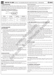
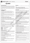
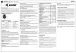
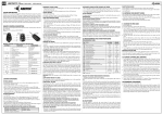
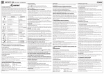
EN
EN
KEETEC CZ 10
CONTROL UNIT OF CENTRAL LOCKING SYSTEM
R
R
USER MANUAL
to be switched on (max. 30 sec.). If you don’t press any button, light duration will be
unlimited. Duration programming will automatically end after 30 seconds.
VEHICLE SEARCHING (only RC MOTO)
Press button
for vehicle searching. Directional lights flashes 10 times.
WARNING: Carefully read following instructions and technical specifica- tions in this manual before installation. The system must be installed and
used only according to this manual. The system is designed for vehicles with
12V power supply. It has to be connected to 12V output and to the ground.
Neither producer or seller of the system is responsible for damages caused by
incorrect installation, using or operating of this product. Unprofessional operation or modification of the system can damage the system alone, or the electric
system of the vehicle and leads to warranty loss. For proper working of the
system we recommend the installation to be made by authorized service.
DESCRIPTION
KEETEC CZ 10 is control unit of central locking system with remote controls designed
for vehicles with 12V power supply. The controller works with the minus-controlled
central locking systems or by adding additional relay (not included) with other types
of central locking systems. Trunk time-programming output can be used for control
different devices in vehicle. Communication between control unit and remote controls
is protected with hopping code.
+
ignition turned off
vehicle unlock
locked vehicle
trunk open
ignition turned off
III. SCHEMATIC
FUNCTION
trunk open
CONDITIONS
(only RC KEY)
„LOCK CHECK“ is turned off
„LOCK CHECK“ is turned on
activation of „LOCK CHECK“ (check of last pressed
button on remote control)
always (only RC MAX)
for more
than1sec.
turn on LED diode in front of remote control
always (RC MAX, RC METAL)
for more
than 1sec.
turn on LED diode in front of remote control
always (RC LINE)
adjust length of LED lighting when button is pressed
always (only RC MAX)
vehicle searching
always (only RC MOTO)
+
antenna
ignition turned off
a: „LOCK CHECK“ activation
b: „LOCK CHECK“ deactivation
for 2sec.
The location of the control unit
Place the control unit from inside the protective plastic dashboard. Attach the antenna
control unit so that it does not touch the metal parts of the vehicle.
vehicle lock
BUTTON
for 1sec.
Remove the plastic covers the dashboard of the vehicle. Find the wires that control
central locking, located on the control unit. For some types of vehicles to be powered
directly by the central locking the door of the car. The testing functions in the vehicle
wiring, use only digital multimeter, and even if you know what function the wire serves.
After determining the wires, disconnect the battery and connect the wiring harness
designed for central locking wires for proper functioning, according to the attached
diagrams. All connections soldered and insulated. After installing central locking plug
from the car battery and insert the fuse into the fuse housing from the central locking.
Protest the proper functioning of the central locking and electric vehicles performance
(ignition, directional lights, ..) Install the plastic covers of the dashboard.
CONNECTOR CN1 (4PIN) - INPUTS AND OUTPUTS
Red (+) power supply +12V (input wire)
Black (-) GND (input wire)
Green (-) unlock -300mA (output wire)
Blue (-) lock -300mA (output wire)
CONNECTOR CN2 (2PIN) - OUTPUTS
Purple (-) trunk open -500mA (input wire). Length of output switching is programmable.
Orange (+) power output for directional lights (output wire). Outputs are separated
by rectifying diodes.
I. REMOTE CONTROL BUTTON DESCRIPTION
for 1sec.
II. SYSTEM INSTALLATION
service button
LED diode
Note: Lock Check function is available only at RC MAX remote controls!
15A
+12V
“LOCK CHECK” FUNCTION (RC MAX)
This function allows you to check which button was pushed last time. Buttons for
locking and unlocking can be checked and therefore user can check, whether he
locked the car or not. LOCK CHECK function is optional and turned off from factory.
You can activate the function by holding buttons and together for two seconds.
When activating, icons for locking and unlocking will blink once. When deactivating,
they will blink twice. If the function is activated, you can check the last pushed button
by briefly pushing button . After that the icon of locking or unlocking will light for
approx. 0,8 sec, depending on which button was pushed last time.
Warning: When the LOCK CHECK function is activated, battery life will be shorter.
LOW BATTERY INDICATOR (RC MAX)
If the battery indicator will flash in blue colour when locking or unlocking vehicle, the
battery in remote control is weak and you have to replace it with new one.
TORCH FUNCTION (RC MAX, RC METAL, RC LINE)
By holding button
on remote control RC MAX, RC METAL and button
on RC
LINE for more than 1 sec, high power LED in front of the remote will light up. LED will
light as long as you hold the button or for a specified time, even if you hold the button longer (only RC MAX). The time how long the LED can glow is adjustable (only
RC MAX).
LED LIGHTS DURATION SETTING ON RC MAX
Duration of LED light can be adjusted from 1 to 30 sec or without limit. Push buttons
and
together for 1 sec. Red LED will flash for 3 sec. After those 3 sec,the LED
will start to flash in 1 sec. intervals. Press the button
for as long as you wish the
light
GND
red
10A
directional lights
(output “+”)
black
unlock “-” 300mA green
(output)
blue
PROGRAMMING TRUNK OUTPUT
Trunk output is factory set to be switched on for 1 second after activation. System
allows user to set these 3 options:
1. activate output for specific time (from 1 to 300 sec.). After trunk output activation,
this output is turned on for specific time.
2. output is permanently turned on when button for trunk open is pushed, and turned
off by next press of this button
3. in steady-state output has “-”12V (grounded). After trunk output activation, there is
no voltage on this output and output for directional lights is permanently turned
on. By next push of button for trunk open, output for trunk open is grounded (“”12V) again and output for directional lights is turned off.
Procedure to program different options:
- disconnect system from power supply and press service button
- keep service button pressed and connect/disconnect system from power supply 3
times within 5 seconds, while the third time system remains connected to the power
supply. LED diode turns on. Release service button.
- LED diode turns off for a while and then turns on to confirm programming mode
(programming procedure is same for all options, proceed as follows according
to each option)
- programming option no.1: press trunk open button 1x. LED diode starts flashing
in one second intervals (number of flashes means how long will be trunk output
turned on after activation). When the number of flashes corresponds to time how
long you want the output turned on, press the button for trunk open again. Length
of turn on for the output is set.
- programming option no.2: press and hold the button for trunk open. LED diode turns
off. When LED diode flashes once, release the button. Output is set.
- programming option no.3: press and hold the button for trunk open. LED diode turns
off and starts flashing in intervals (one, two). After second flash release the button.
Output is set.
SYSTEM RESET
- disconnect system from power supply and press service button
- keep service button pressed and connect/disconnect system from power supply 10
times within 13 seconds, while the tenth time system remains connected to the
power supply. Release service button.
- directional lights flashes 3x. System is now reset to factory settings, also all remote
controls are deleted from memory.
Note: CZ 10 contains remote controls operating in band 433,92 MHz. Ask your
dealer for declaration of conformity for CZ 10 and remote controls.
orange
purple
- LED diode on control unit starts flashing to confirm that you entered into programming
mode
- if you want to remove old remote controls when programming new ones, press lock
button (factory settings) on already programmed remote control. Flashing LED
diode turns on for two seconds, then starts to flash again.
- if you don’t want to remove old remote controls when programming new ones, press
unlock button on already programmed remote control. Flashing LED diode turns
on for five seconds, then starts to flash again.
- programming ends automatically after 10 seconds
trunk open “-” 500mA
(output)
lock “-” 300mA
(output)
IV. PROGRAMMING REMOTE CONTROLS
System can be programmed with up to 10 pcs of remote controls.
- disconnect system from power supply and press service button
- keep service button pressed and connect/disconnect system from power supply 5
times within 7 seconds, while the fifth time system remains connected to the power
supply. Release service button.
- LED diode on control unit starts flashing to confirm that you entered into programming
mode and directional lights flashes 5 times.
- press any button on remote control within 5 seconds.
- successful programming of remote control is confirmed by flash of directional lights
(1x for RC1, 2x for RC2 ...)
- programming ends automatically after 5 seconds after last remote control is
programmed
Add or delete programmed remotes when programming new remote
controls
- disconnect system from power supply and press service button
- keep service button pressed and connect/disconnect system from power supply 7
times within 10 seconds, while the seventh time system remains connected to the
power supply. Release service button.