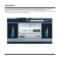
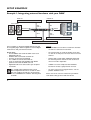
1
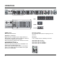
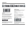
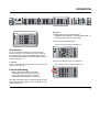
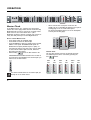
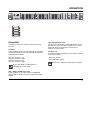
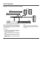
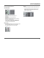
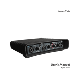
Digital Konnekt x32
User’s Manual
English Version
IMPORTANT SAFETY INSTRUCTIONS
The lightning flash with an arrowhead symbol within
an equilateral triangle is intended to alert the user to
the presence of uninsulated “dangerous voltage”
within the product's enclosure that may be of sufficient
magnitude to constitute a risk of electric shock to persons.
1
2
3
4
5
6
7
8
9
10
11
12
13
14
Read these instructions.
Keep these instructions.
Heed all warnings.
Follow all instructions.
Do not use this apparatus near water.
Clean only with dry cloth.
Do not block any ventilation openings. Install in accordance
with the manufacturer's instructions.
Do not install near any heat sources such as radiators, heat
registers, stoves, or other apparatus (including amplifiers)
that produce heat.
Do not defeat the safety purpose of the polarized or
grounding-type plug. A polarized plug has two blades with
one wider than the other. A grounding type plug has two
blades and a third grounding prong. The wide blade or the
third prong are provided for your safety. If the provided plug
does not fit into your outlet, consult an electrician for
replacement of the obsolete outlet.
Protect the power cord from being walked on or pinched
particularly at plugs, convenience receptacles, and the point
where they exit from the apparatus.
Only use attachments/accessories specified by the
manufacturer.
Use only with the cart, stand, tripod, bracket, or
table specified by the manufacturer, or sold with the
apparatus. When a cart is used, use caution when
moving the cart/apparatus combination to avoid
injury from tip-over.
Unplug this apparatus during lightning storms or when
unused for long periods of time.
Refer all servicing to qualified service personnel. Servicing
is required when the apparatus has been damaged in any
way, such as power-supply cord or plug is damaged, liquid
has been spilled or objects have fallen into the apparatus,
the apparatus has been exposed to rain or moisture, does
not operate normally, or has been dropped.
The exclamation point within an equilateral triangle is
intended to alert the user to the presence of important
operating and maintenance (servicing) instructions in
the literature accompanying the product.
Warning!
•
•
•
•
•
To reduce the risk of fire or electrical shock, do not expose
this equipment to dripping or splashing and ensure that no
objects filled with liquids, such as vases, are placed on the
equipment.
This apparatus must be earthed.
Use a three wire grounding type line cord like the one
supplied with the product.
Be advised that different operating voltages require the use
of different types of line cord and attachment plugs.
Check the voltage in your area and use the correct type.
See table below:
Voltage
Line plug according to standard
110-125V
UL817 and CSA C22.2 no 42.
220-230V CEE 7 page VII, SR section
107-2-D1/IEC 83 page C4.
240V
•
•
•
•
•
BS 1363 of 1984.
Specification for 13A fused
plugs and switched and
unswitched socket outlets.
This equipment should be installed near the socket
outlet and disconnection of the device should be easily
accessible.
To completely disconnect from AC mains, disconnect the
power supply cord from the AC receptacle.
The mains plug of the power supply shall remain readily
operable.
Do not install in a confined space.
Do not open the unit – risk of electric shock inside.
Caution:
You are cautioned that any change or modifications not
expressly approved in this manual could void your authority to
operate this equipment.
Service
•
•
There are no user-serviceable parts inside.
All service must be performed by qualified personnel.
a
EMC / EMI & CERTIFICATE OF CONFORMITY
EMC/EMI
This equipment has been tested and found to comply
with the limits for a Class B Digital device, pursuant to
part 15 of the FCC rules.
These limits are designed to provide reasonable
protection against harmful interference in residential
installations. This equipment generates, uses and can
radiate radio frequency energy and, if not installed and
used in accordance with the instructions, may cause
harmful interference to radio communications. However,
there is no guarantee that interference will not occur in a
particular installation. If this equipment does cause
harmful interference to radio or television reception,
which can be determined by turning the equipment off
and on. The user is encouraged to try to correct the
interference by one or more of the following measures:
•
•
•
•
Reorient or relocate the receiving antenna.
Increase the separation between the equipment and
receiver.
Connect the equipment into an outlet on a circuit
different from that to which the receiver is connected.
Consult the dealer or an experienced radio/TV
technician for help.
For Customers in Canada:
This Class B digital apparatus complies with Canadian
ICES-003.
Cet appareil numérique de la classe B est conforme à la
norme NMB-003 du Canada.
Certificate of Conformity
TC Electronic A/S, Sindalsvej 34, 8240
Risskov, Denmark, hereby declares on own
responsibility that the following product:
Digital Konnekt x32
that is covered by this certificate and
marked with CE-label conforms with
following standards:
EN 60065
Safety requirements for mains
(IEC 60065) operated electronic and
related apparatus for household
and similar general use
EN 55103-1 Product family standard for
audio,video, audio-visual and
entertainment lighting control
apparatus for professional
use. Part 1: Emission.
EN 55103-2 Product family standard for
audio, video, audio-visual and
entertainment lighting control
apparatus for professional
use. Part 2: Immunity.
With reference to regulations in following
directives:
73/23/EEC, 89/336/EEC
Issued in Risskov, June 2007
Mads Peter Lübeck
Chief Executive Officer
b
TABLE OF CONTENTS
INTRODUCTION
APPENDIX
Important Safety Instructions . . . . . . . . . . . . . .a
Certificate of Conformity . . . . . . . . . . . . . . . . . .b
Table Of Contents . . . . . . . . . . . . . . . . . . . . . . .3
Introduction . . . . . . . . . . . . . . . . . . . . . . . . . . . .5
Technical specifications . . . . . . . . . . . . . . . . .28
OPERATION
AES/SPDIF/TOS in section . . . . . . . . . . . . . . .6
AES+SPDIF+TOS routing . . . . . . . . . . . . . . . .7
ADAT in . . . . . . . . . . . . . . . . . . . . . . . . . . . . . .8
ADAT routing . . . . . . . . . . . . . . . . . . . . . . . . . .8
Firewire in . . . . . . . . . . . . . . . . . . . . . . . . . . . . .9
Firewire routing . . . . . . . . . . . . . . . . . . . . . . . . .9
Master Clock section . . . . . . . . . . . . . . . . . . .10
Setup Util . . . . . . . . . . . . . . . . . . . . . . . . . . . .11
Scenes . . . . . . . . . . . . . . . . . . . . . . . . . . . . . .12
Monitor . . . . . . . . . . . . . . . . . . . . . . . . . . . . . .12
Rear Panel View . . . . . . . . . . . . . . . . . . . . . . .13
The integrator . . . . . . . . . . . . . . . . . . . . . . . . .14
SETUP EXAMPLES
Example 1: Integrating external hardware
with your DAW . . . . . . . . . . . . . . . . . . . . . . . .16
Example 2: Conventional audio interface . . . .20
Example 3: PA setup . . . . . . . . . . . . . . . . . . .22
Digital Konnekt x32 and ProTools . . . . . . . . .24
TC NEAR CONTROL PANEL
Buffer Size . . . . . . . . . . . . . . . . . . . . . . . . . . .26
System Clock . . . . . . . . . . . . . . . . . . . . . . . . .26
Status . . . . . . . . . . . . . . . . . . . . . . . . . . . . . . .27
Software update . . . . . . . . . . . . . . . . . . . . . . .27
Versions . . . . . . . . . . . . . . . . . . . . . . . . . . . . .27
Reset to default . . . . . . . . . . . . . . . . . . . . . . .27
TC Electronic, Sindalsvej 34, DK-8240 Risskov – [email protected]
English Version
Manual revision 1.01 – SW – V 1.00
3
INTRODUCTION
Digital Konnekt x32 – Patchbay, Format Converter, Audio Interface and hardware integrator
Digital Konnekt x32 not only puts patching and signal-splitting under preset control, and converts between formats. What
comes out is also better than what went in.
Thanks to System 6000 grade clock clean-up and jitter rejection, Digital Konnekt x32 makes your other audio devices and
DAW perform better while at the same time facilitating digital interfacing. Digital Konnekt handles AES, ADAT, SPDIF and
Firewire audio, and provides extra features such as computer independent operation, convenient monitoring and UI lock.
Clock and jitter reduction
Thanks to System 6000 grade clock clean-up and jitter rejection, Digital Konnekt x32 makes your other audio devices and
DAW perform better while at the same time facilitating digital interfacing. Digital Konnekt x32 takes any AES, ADAT, SPDIF
or Firewire signal and transforms it into a professional and distributed Reference Clock. A solid clock foundation improves
the reliability of digital interfacing as well as the performance of AD and DA converters in your entire studio.
Synchronous routing is 24 bit transparent, even between formats, while sample rate converters may be inserted on inputs
that run free or use a different clock reference.
All the Tools – One Toolbox
Up until now, the pro audio market has only seen single function units such as format- and sample rate converters,
patchbays, house clocks and audio interfaces offering digital signal handling. Never before have these essential functions
been incorporated in a single platform linking your entire fleet of digital devices to your DAW.
Make your favorite hardware the heart of your DAW
With Digital Konnekt and the new Integrator plug-in, you can now utilize your trusted and favorite digital hardware tools
within your DAW system.
Featuring TC's plug-in streaming technology, the Integrator plug-in (VST and AU) facilitates seamless integration of all
external units with your recording setup; once connected, adding the unique sound of your Reverb4000 (or any other
external digital hardware unit – TC or non-TC) is just a mouse click away. And with the built-in latency roundtrip measuring
feature and your DAW’s latency compensation, your projects will not suffer from latency induced by external hardware.
Features
• Flexible digital patchbay
• Format Converter
• 16x16 ch Audio interface
• Seamless DAW integration with Integrator plug-in
• Unique digital matrix style UI for direct selection of
signals
•
•
•
•
•
8 ch of sample rate conversion on board for optimal
digital adaptation
Analog outs (phone and balanced line) for monitoring
Scene recall enabling instant recall of full setups
Front panel UI lock to prevent unintended use
JET™ technology ensures rock solid digital signal
handling
Should this manual leave any of your questions unanswered, please use the TC Support service, which you
can access via our website www.tcelectronic.com. Over a period of time, we will collect the most frequently
asked questions and update the manual accordingly. Manual updates are available for download on our
website in PDF format. The current manual revision number is found at the bottom of page 3.
5
OPERATION
aes+spdif+tos
aes/spdif/tos in
TOS IN 5/6
TOS
SPDIF
SRC
1-2
3-4
5-6
adat
7-8
mon
aes+spdif+tos
adat in
1-2
3-4
5-6
adat
7-8
mon
aes+spdif+tos
firewire in
1-2
3-4
5-6
adat
mon
7-8
1-2
NS
1/2
1-2
1-8
1/2
3/4
3-4
DS
3/4
3-4
9-16
3/4
3-4
5/6
5-6
5/6
5-6
5/6
5-6
7-8
7/8
1/2
master clock
1-2
setup/util
44.1k
digitalkonnekt x32
adat
1-8
7/8
FRONT
aes/spdif clock master
SRC
7-8
LOCK
SIG
adat
1-8
7/8
LOCK
SIG
7-8
x4
aes
/spdif
aes+spdif+tos
aes/spdif/tos in
TOS
SPDIF
SRC
1/2
1-2
3-4
5-6
adat
7-8
5-6
FORMAT CONVERTER | PATCHBAY | FIREWIRE IO
FRONT
aes/spdif clock master
7/8
adat
1-8
AES/SPDIF/TOS In
This is the input select section for the AES/SPDIF and
Toslink inputs on Digital Konnekt x32.
When neither Toslink or S/PDIF inputs are selected (no
LEDs are lit), Digital Konnekt x32 defaults to the signal
present on the AES inputs.
7/8
1/2
3/4
5/6
7/8
3/4
5/6
7/8
SPDIF
7-8
MAIN
1-2
IN
96k
3-4
ADAT MAIN OUT
TOS
1-2
96k
3-4
TYP
MA
TC
Selecting channels
For each input channel pair one input type can be
selected.
Example 1
In the example below the following is selected:
Input
Input
Input
Input
channel
channel
channel
channel
aes/spdif/tos in
TOS
SPDIF
SRC
1
3
5
FRONT
aes/spdif clock master
6
5/6
IN
OUT
1/2
Toslink
TOS IN 5/6 - connection
Digital Konnekt x32 handles up to 6 input channels of
optical SPDIF via Toslink. Input connections for channels
1/2 and 3/4 are located on the rear panel.
Input connection for channels 5/6 is located on the front.
+phones
spdif I/O
LOCK
SIG
POWER switch
Mains power on/off switch.
monitor
aes/ebu outputs
3/4
3-4
5/6
4
HOLD TO STORE SCENE
a
1-2
3/4
digitalkonnekt x32
mon
3
lock device
HOLD TO UN-LOCK
aes/ebu inputs
TOS IN 5/6
2
input signal
P security
INT
hold to select input
1/2
1
AES pro out
monitor LEDs
SEL
LOCK
SIG
AES
dual wire XLR
x2
adat
adat
1-8
192kHz fs
48k
WCK in
FORMAT CONVERTER | PATCHBAY | FIREWIRE IO
scenes
clock rate
firewire
7
L
pair
pair
pair
pair
1/2: Tos
3/4: SPDIF
5/6: AES/EBU
7/8: AES/EBU
OPERATION
SRC
Digital Konnekt x32 has 4 sample rate converters and
thus features individual sample rate conversion on any
input channel pair in this section OR on all ADAT
channels.
When activating sample rate conversion SRC in the
ADAT section, any selected sample rate conversion in
the AES/SPDIF/TOS section is deselected.
AES+SPDIF+TOS Routing
This is the routing section for the AES/SPDIF and Toslink
inputs.
aes+spdif+tos
1-2
3-4
5-6
adat
7-8
mon
1-2
3-4
5-6
adat
1-8
7-8
Each input channel pair can be routed to any
AES/SPDIF/TOS output and to ADAT outputs.
Furthermore any input channel pair can be routed to
monitor+headphone out.
7
OPERATION
aes+spdif+tos
aes/spdif/tos in
TOS IN 5/6
TOS
SPDIF
SRC
1-2
3-4
5-6
adat
7-8
mon
aes+spdif+tos
adat in
1-2
3-4
5-6
adat
7-8
mon
aes+spdif+tos
firewire in
1-2
3-4
5-6
adat
7-8
mon
1-2
NS
1/2
1-2
1-8
1/2
3/4
3-4
DS
3/4
3-4
9-16
3/4
3-4
5/6
5-6
5/6
5-6
5/6
5-6
1/2
master clock
1-2
setup/util
44.1k
FORMAT CONVERTER | PATCHBAY | FIREWIRE IO
7/8
FRONT
aes/spdif clock master
1-2
3-4
5-6
adat
7-8
mon
1/2
DS
3/4
3-4
5/6
5-6
7/8
7-8
LOCK
SIG
NS & DS - (Normal and Double Sample Rate)
Using these switches you can alternate between using
normal or double sample rate for the ADAT format.
At normal sample rate, 44.1 or 48 kHz, up to eight
channels can be sent on a single lightpipe cable. Use
MAIN 1-2 connections on the rear panel.
1-2
96k
3-4
7/8
adat
x4
7-8
SEL
aes
/spdif
LOCK
SIG
2
INT
hold to select input
input signal
monitor LEDs
P security
lock device
HOLD TO UN-LOCK
3
4
monitor
HOLD TO STORE SCENE
+phones
ADAT Routing
The four ADAT channel pairs can be routed to any pair of
AES+SPDIF+TOS channels and to the eight ADAT
channels simultaneously as well.
Normal sample rate
This section routes the signal present on the ADAT in
connection. The signal can be routed to AES/EBU,
SPDIF, Toslink and ADAT outputs and any pair of
channels can also be routed to monitor out.
IN
7-8
adat
1-8
1
AES pro out
x2
Example 2
In the example below the following is selected:
ADAT In
MAIN
adat
1-8
dual wire XLR
f
1-2
adat
1-8
7/8
SRC
LOCK
SIG
NS
SRC
7-8
LOCK
SIG
aes+spdif+tos
adat in
adat
1-8
192kHz fs
48k
WCK in
digitalkonnekt x32
scenes
clock rate
firewire
ADAT MAIN OUT
TOS
1-2
ADAT ch.
ADAT ch.
ADAT ch.
ADAT ch.
1-2
3-4
5-6
7-8
is
is
is
is
sent
sent
sent
sent
to AES+SPDIF+TOS
to AES+SPDIF+TOS
to AES+SPDIF+TOS
to AES+SPDIF+TOS
ch.
ch.
ch.
ch.
1-2
3-4
5-6
7-8
All ADAT channels are sent to ADAT out.
ADAT channels 1-2 are sent to the analog monitor and
headphones outputs.
aes+spdif+tos
adat in
NS
1/2
DS
3/4
96k
1-2
3-4
5-6
adat
7-8
1-2
3-4
5-6
5/6
3-4
SRC
7/8
mon
adat
1-8
7-8
LOCK
SIG
At double sample rate, 88.2 or 96kHz, four channels per
lightpipe connection can be sent. To facilitate eight
channels, two lightpipe cables for inputs and 2 lightpipe
cables for outputs must be used.
8
SRC - (Sample Rate Conversion)
Press to activate sample rate conversion on all ADAT
input channels. This will deselect any previously selected
sample rate conversion.
OPERATION
aes+spdif+tos
aes/spdif/tos in
TOS IN 5/6
TOS
SPDIF
SRC
1-2
3-4
5-6
adat
7-8
mon
aes+spdif+tos
adat in
1-2
3-4
5-6
adat
7-8
mon
aes+spdif+tos
firewire in
1-2
3-4
5-6
adat
7-8
mon
1-2
NS
1/2
1-2
1-8
1/2
3/4
3-4
DS
3/4
3-4
9-16
3/4
3-4
5/6
5-6
5/6
5-6
5/6
5-6
7-8
7/8
1/2
master clock
1-2
setup/util
44.1k
digitalkonnekt x32
aes/spdif clock master
1-8
1/2
9-16
3/4
1-2
3-4
5-6
7-8
SRC
LOCK
SIG
aes+spdif+tos
firewire in
adat
1-8
7/8
FRONT
adat
mon
m
1-2
3-4
adat
1-8
1
AES pro out
2
input signal
3
x2
adat
x4
7-8
SEL
aes
/spdif
LOCK
SIG
dual wire XLR
INT
hold to select input
monitor LEDs
P security
lock device
HOLD TO UN-LOCK
4
HOLD TO STORE SCENE
monitor
+phones
Example 3
A typical setting for this section would be:
• Routing firewire channels 1-8 to AES+SPDIF+TOS 1-8
• Routing firewire channels 9-16 to ADAT.
5-6
5/6
LOCK
SIG
adat
1-8
LOCK
SIG
7-8
7/8
7/8
192kHz fs
48k
WCK in
FORMAT CONVERTER | PATCHBAY | FIREWIRE IO
scenes
clock rate
firewire
adat
1-8
This is set up in the following way:
7-8
h
•
Press 1-8 to route firewire channels 1-8
aes+spdif+tos
firewire in
Firewire In
1-8
1/2
9-16
3/4
Up to 16 channels of audio can be received via the
firewire connection. This section route these channels.
The signal can be routed to, AES/EBU, SPDIF (coax),
Tos-link and ADAT outputs. Any channel pair can also be
routed to monitor out.
1-2
3-4
5-6
adat
7-8
mon
1-2
3-4
5-6
5/6
adat
1-8
7/8
7-8
LOCK
SIG
We have routed channels 1/2 to monitor out.
1-8 & 9-16
Select 1-8 to route firewire channels 1-8 and select 9-16
to route channels 9-16.
Firewire Routing
-
Firewire channels 1-8 can be routed to
AES+SPDIF+TOS outputs or to ADAT out.
Firewire channels 9-16 can be routed to
AES+SPDIF+TOS outputs or to ADAT out.
•
Press 9-16 to route firewire channels 9-16
aes+spdif+tos
firewire in
1-8
1/2
9-16
3/4
1-2
3-4
5-6
adat
7-8
1-2
3-4
5-6
5/6
7/8
mon
adat
1-8
7-8
LOCK
SIG
Note that ADAT channels are handled in groups of eight
channels thus either channels 1-8 OR channels 9-16 are
routed to ADAT out.
9
OPERATION
aes+spdif+tos
aes/spdif/tos in
TOS IN 5/6
TOS
SPDIF
SRC
1-2
3-4
5-6
adat
7-8
mon
aes+spdif+tos
adat in
1-2
3-4
5-6
adat
7-8
mon
aes+spdif+tos
firewire in
1-2
3-4
5-6
adat
mon
7-8
1-2
NS
1/2
1-2
1-8
1/2
3/4
3-4
DS
3/4
3-4
9-16
3/4
3-4
5/6
5-6
5/6
5-6
5/6
5-6
7-8
7/8
1/2
master clock
1-2
setup/util
44.1k
digitalkonnekt x32
7/8
FRONT
aes/spdif clock master
LOCK
SIG
adat
1-8
7-8
SRC
7/8
adat
1-8
LOCK
SIG
Master Clock
•
In any digital system, one, and only one clock can be
master. Due to the highly stable clock in the DICEII chip,
Digital Konnekt x32 can be used as an excellent master
clock. However, due to the DICEII JET™ (Jitter
Elimination Technique) and the 4 sample rate converters
it may also lock perfectly to external digital devices.
aes
/spdif
hold to select input
AES/SPDIF/OPTO section located on the left side of
the front panel corresponding to the channel pair you
want to use as clock master:
aes
/spdif
3
P security
lock device
4
monitor
+phones
HOLD TO STORE SCENE
When connected to a computer via firewire the
sample rate is set according to options on the System
Settings page in the TC Near control panel.
For further information please refer to the description
of the System Setting page.
mon
master clock
setup/util
44.1k
192kHz fs
dual wire XLR
48k
AES pro out
WCK in
x2
5-6
adat
adat
1-8
sc
clock rate
3-4
input signal
x4
7-8
monitor LEDs
SEL
aes
/spdif
INT
hold to select input
P security
lock device
HOLD TO UN-LOCK
HO
Internal Clock
You may also choose to lock to an internal clock rate.
The following rates can be selected by pressing the
INT
button.
SEL
INT
f
put
H
44.1
kHz
48
kHz
clock rate
e
44.1k
n
aster
44.1k
n
96
kHz
44.1k
e
44.1k
n
44.1k
n
x2
x2
x2
x4
x4
x4
x4
x4
INT
INT
t
SEL
t
48k
x2
x4
SEL
INT
INT
ut
SEL
INT
ut
44.1k
n
x2
SEL
clock rate
e
48k
x2
SEL
192
kHz
clock rate
e
48k
48k
n
176.4
kHz
clock rate
clock rate
e
48k
SEL
t
88.2
kHz
clock rate
e
48k
10
2
input signal
HOLD TO UN-LOCK
firewire
SRC
You cannot activate SRC on the channel pair you
attempt to use as clock master.
1
AES pro out
monitor LEDs
INT
1-2
/tos in
F
x4
SEL
hold to select input
adat
How to set the Master Clock
• Press WCK to lock to wordclock input
• Press ADAT to lock to the ADAT input
• Press AES/SPDIF to lock to a signal present on AES,
SPDIF or Tos inputs. AES/SPDIF/TOS inputs are
divided into four pairs (Toslink only three pairs), of
two channels and you may lock to any of these pairs.
To select which channel pair to lock to, follow the
procedure described below.
• While holding
press the SRC button in the
7-8
LOCK
SIG
dual wire XLR
x2
adat
adat
1-8
192kHz fs
48k
WCK in
FORMAT CONVERTER | PATCHBAY | FIREWIRE IO
scenes
clock rate
firewire
INT
t
OPERATION
aes+spdif+tos
aes/spdif/tos in
TOS IN 5/6
TOS
SPDIF
SRC
1-2
3-4
5-6
adat
7-8
mon
aes+spdif+tos
adat in
1-2
3-4
5-6
adat
7-8
mon
aes+spdif+tos
firewire in
1-2
3-4
5-6
adat
7-8
mon
1-2
NS
1/2
1-2
1-8
1/2
3/4
3-4
DS
3/4
3-4
9-16
3/4
3-4
5/6
5-6
5/6
5-6
5/6
5-6
7-8
7/8
1/2
master clock
1-2
setup/util
44.1k
digitalkonnekt x32
7/8
FRONT
aes/spdif clock master
setup/util
adat
1-8
7-8
SRC
LOCK
SIG
7/8
LOCK
SIG
adat
1-8
LOCK
SIG
adat
1-8
192kHz fs
dual wire XLR
1
AES pro out
2
48k
WCK in
FORMAT CONVERTER | PATCHBAY | FIREWIRE IO
scenes
clock rate
firewire
x2
adat
7-8
x4
SEL
aes
/spdif
hold to select input
INT
input signal
monitor LEDs
P security
lock device
HOLD TO UN-LOCK
3
4
HOLD TO STORE SCENE
monitor
+phones
sce
192kHz fs
dual wire XLR
AES pro out
input signal
monitor LEDs
P security
lock device
HOLD TO UN-LOCK
HOLD
Setup/Util
Consider this section the master section of the format
converter.
192 kHz fs
With this option selected, 4 input channels of AES signal
at 192 khz on dual wire XLR can be handled. Channels
are distributed as follows:
AES
AES
AES
AES
1/2
3/4
5/6
7/8
:
:
:
:
Channel
Channel
Channel
Channel
1
1
2
2
Left
Right
Left
Right
Input Signal Monitor LEDs
The blue LOCK SIG LEDs normally indicate the current
lock state for each of the input sections. However, these
LEDs can also be used as input meters for these
sections. Press to activate.
Security Lock
To avoid unintended operation of the front panel controls,
these can be locked.
- Press once to lock
- Press and hold to unlock
Monitor level, and power switch cannot be locked.
Beware that SPDIF or TOS signals are
unavailable in 192 kHz mode!
AES - (AES or SPDIF Status bits)
This key allows you to switch between sending AES
(professional) or SPDIF (consumer) status bits on AES
outputs.
11
OPERATION
aes+spdif+tos
aes/spdif/tos in
TOS IN 5/6
TOS
SPDIF
SRC
1-2
3-4
5-6
adat
7-8
mon
aes+spdif+tos
adat in
1-2
3-4
5-6
adat
7-8
mon
aes+spdif+tos
firewire in
1-2
3-4
5-6
adat
7-8
mon
1-2
NS
1/2
1-2
1-8
1/2
3/4
3-4
DS
3/4
3-4
9-16
3/4
3-4
5/6
5-6
5/6
5-6
5/6
5-6
7-8
7/8
1/2
master clock
1-2
setup/util
44.1k
digitalkonnekt x32
7/8
FRONT
aes/spdif clock master
adat
1-8
7-8
LOCK
SIG
SRC
7/8
LOCK
SIG
scenes
fs
R
1
out
2
al
3
s
ty
4
vice
K
HOLD TO STORE SCENE
monitor
+phones
Scenes
Up to four Scene presets can be stored and recalled via
the four scene buttons. A Scene preset stores all current
settings except power on/off status and the position of
the monitor level knob.
Operation is simple:
• Press and hold to store a Scene preset
• Press to recall a Scene preset
Monitor
The Monitor section provides a 1/4” TRS jack connection
for headphones out and a knob for level control. The
knob controls both the monitor and headphones level.
12
adat
1-8
LOCK
SIG
adat
1-8
192kHz fs
dual wire XLR
1
AES pro out
2
48k
WCK in
FORMAT CONVERTER | PATCHBAY | FIREWIRE IO
scenes
clock rate
firewire
x2
adat
7-8
x4
SEL
aes
/spdif
hold to select input
INT
input signal
monitor LEDs
P security
lock device
HOLD TO UN-LOCK
3
4
HOLD TO STORE SCENE
monitor
+phones
REAR PANEL VIEW
aes/ebu inputs
aes/ebu outputs
MAIN
spdif I/O
1-2
IN
96k
3-4
ADAT MAIN OUT
TOS
1-2
96k
100-240 V~AC 50-60Hz, 15W
3-4
L
12345687-9872
TYPE: PB001
MADE IN DENMARK
IN
OUT
monitor
TC ELECTRONIC
R
R
C
1/2
3/4
5/6
7/8
1/2
3/4
5/6
7/8
1/2
3/4
5/6
7/8
firewire
OUT
WCK
IN
UL60065
EN/IEC 60065
CSA FILE | LR108093
US
PROFESSIONAL AUDIO EQUIPMENT
THIS CLASS B DIGITAL DEVICE MEETS ALL REQUIREMENTS OF THE CANADIAN INTERFERENCECAUSING EQUIPMENT REGULATIONS AND COMPLIES WITH PART 15 OF THE FCC RULES.
OPERATION SUBJECT TO CONDITIONS STATED IN THE MANUAL.
1 - Analog Out
Balanced analog outputs on 1/4” TRS jacks. The level of
the outputs is controlled by the monitor level control knob
on the front panel.
Toslink:
- Digital Konnekt x32 handles up to 6 input channels
and 4 output channels of optical SPDIF via Toslink.
Input for Toslink channels 5/6 is located on the front.
2 - AES/EBU inputs
Female XLR connectors for up to 8 AES channels.
9 - Firewire
Firewire connection for connecting Digital Konnekt x32 to
a computer and/or linking up to 4 units.
3 - AES/EBU outputs
Male XLR connectors for up to 8 AES channels.
4 - SPDIF I/O
Upper row:
- RCA connectors for 8 input channels of SPDIF
10 - Wordclock Out
Due to the DICE II chip, Digital Konnekt x32 can act as
an excellent master clock generator for you setup.
Connect via standard BNC plugs.
Lower row:
- RCA connectors for 8 output channels of SPDIF
11 - Wordclock In
Connect your external wordclock generator here and
select “WCK in@ on the front panel.
5-8 ADAT/Toslink I/O connectors
The optical connections carry either Toslink (optical
SPDIF) or ADAT signal.
12 - Power In
The switchmode power-supply accepts from 100 to
240VAC.
ADAT:
- At normal sample rate 8 channels of ADAT is carried
on a single lightpipe. Use the MAIN connector.
- At double sample rate 8 channels of ADAT is
distributed on 2 lightpipe connectors. Use both the MAIN
and the 96 kHz connections.
13
INTEGRATOR
The Integrator plug-in for Digital Konnekt x32 makes integration of external hardware into your DAW environment
seamless. It offers a “plug-in” audio routing representation of your external digital effects processors.
Integrator as it operates as a normal VST/AU plug-in and can be inserted on any track, utilizing external effects as a send
or insert effects on any track or bus in your host application.
14
INTEGRATOR
Installation
The Integrator plug-in is automatically installed when the
TC Near control panel is installed.
where Integrator is inserted.
Parameters
Lock
Green - indicates correct lock between the selected
external digital device and Digital Konnekt x32.
Red - indicates “no lock”. Check connections and
settings.
Device
Selects the connected digital devices you are setting up.
1st audio channel
Your DAW detects audio channels on the Digital Konnekt
x32 and label these automatically. As the Integrator acts
as a stereo plug-in interface between the DAW and
external stereo devices, you always select two channel
(by default). These are identified by the name of the first
channel. In the illustration on the previous page, channel
pair 9/10 is selected even though the label says “fw ch
9”.
When inserting Integrator on a mono track it still
occupies a pair of channels.
Calibrate
Integrating external digital devices will introduce a short
latency. But your host application can be set up to
compensate for this using the calibrate function in the
Integrator.
•
Press CALIBRATE to measure the total roundtrip
latency including the latency within the external device.
The latency compensation feature of the host application
will then make sure to compensate for this latency.
This procedure should be carried out on each audio track
15
SETUP EXAMPLES
Example 1: Integrating external hardware with your DAW
FINALIZER 96K
REVERB 4000
REVERB 4000 FINALIZER
ACTIVE SPEAKERS
SPDIF
COAX 1/2
MONITOR OUT
aes+spdif+tos
aes/spdif/tos in
TOS IN 5/6
TOS
SPDIF
SRC
1/2
1-2
3-4
5-6
adat
7-8
mon
aes+spdif+tos
adat in
1-2
NS
1/2
3-4
DS
3/4
1-2
3-4
5-6
adat
7-8
ADAT
FIREWORX
mon
aes+spdif+tos
firewire in
1-2
1-8
1/2
3-4
9-16
3/4
1-2
3-4
5-6
adat
7-8
mon
master clock
1-2
setup/util
3-4
44.1k
FRONT
aes/spdif clock master
7/8
LOCK
SIG
adat
1-8
7-8
5-6
5/6
SRC
7/8
adat
1-8
LOCK
SIG
7-8
adat
1-8
dual wire XLR
AES pro out
NON TC PRODUCT
FIREWIRE
1
2
x2
5-6
5/6
7/8
LOCK
SIG
192kHz fs
48k
WCK in
5-6
5/6
digitalkonnekt x32
FORMAT CONVERTER | PATCHBAY | FIREWIRE IO
scenes
clock rate
firewire
3/4
adat
7-8
x4
SEL
aes
/spdif
hold to select input
INT
input signal
monitor LEDs
P security
lock device
HOLD TO UN-LOCK
3
4
monitor
HOLD TO STORE SCENE
+phones
C400XL
SPDIF
COAX 3/4
AES 5/6
COMPUTER
NON TC PRODUCT
FIREWORX
AES 7/8
C400XL
In this example we show how Digital Konnekt x32 and
the Integrator plug-in allow integration of external digital
effect devices with your DAW via Firewire.
Objects:
- Reverb 4000 is an excellent reverb and we intend to
use this as a send effect in our DAW.
Connections:
• Reverb 4000 is connected via SPDIF coax 1/2 on
Digital Konnekt x32
• Finalizer 96K is connected via ADAT I/O
• FireworX is connected via AES 5/6
• The C400XL is connected via AES 7/8
• A non TC Electronic related product with SPDIF
option is connected via SPDIF coax 3/4
• Digital Konnekt x32 is connected to your computer
via Firewire
-
The FireworX has an excellent vocoder preset and
we want to use this preset an insert effect on a mono
channel.
-
Finalizer 96k is a top quality multiband compressor
for mastering and we want to use this as an insert
effect on a master output bus.
-
C400XL is a stereo compressor and should be
inserted on a track, a group track or on a bus.
-
We leave it up to you to suggest how the “non-TC
product” should be used
The example above illustrates how several
different digital formats can be used at the same
time. We could just as well have connected the
the Reverb4000 and the Finalizer 96k using AES
or SPDIF.
16
Please refer to the reference manual for you DAW to
learn about setting up insert and send effects.
SETUP EXAMPLES
Setting up Digital Konnekt x32
AES/SPDIF/TOS in
• SPDIF is selected for channel pairs 1/2 and 3/4.
• AES is selected for channel pairs 5/6 and 7/8 (no
LEDs are lit).
aes+spdif+tos
aes/spdif/tos in
TOS
SPDIF
SRC
1-2
1/2
3-4
5-6
7-8
3/4
Clock
• In the DAW you select External - as clock source.
This allows you to use the Digital Konnekt x32 as
master clock.
• Make sure that all external devices are set to lock to
external clock
• The “non- TC Electronic” product is set to lock to
external clock. - If this is not possible - use the
sample rate converter on Digital konnekt x32 for
channel 3/4.
5/6
Now the Digital Konnekt x32 operates as a digital
patchbay as well as an excellent master clock.
7/8
FRONT
LOCK
SIG
aes/spdif clock master
master clock
setup/util
clock rate
ADAT in
• We select Normal Sample rate and route ADAT
channels to ADAT out.
firewire
44.1k
x2
x4
SEL
adat in
NS
DS
1/2
1-2
3-4
5-6
aes
/spdif
adat
7-8
dual wire XLR
AES pro out
WCK in
adat
aes+spdif+tos
192kHz fs
48k
hold to select input
INT
input signal
monitor LEDs
P security
lock device
HOLD TO UN-LOCK
3/4
5/6
SRC
adat
1-8
7/8
LOCK
SIG
Firewire
• In the Firewire section we choose to monitor
channels 9/10.
aes+spdif+tos
firewire in
1-8
1/2
9-16
3/4
1-2
3-4
5-6
adat
7-8
1-2
3-4
5-6
5/6
7/8
mon
adat
1-8
7-8
LOCK
SIG
Therefore you must route the main output channels from
your DAW to outputs 9/10.
17
SETUP EXAMPLES
The Integrator
Now that Digital Konnekt x32 is set up it is time to set up
your DAW application utilizing the Integrator plug-in.
For each external effect, one instance of the Integrator
plug-in must be set up. Each of the Integrator instances
then represents one external effect.
This example illustrates how Integrator is inserted in
Cubase LE with Integrator set up according to the
physical connections as shown in the illustration on page 16.
•
•
For each external effects unit you want to integrate you
make the same considerations as you are used to when
setting up software plug-in effects.
- insert effects are inserted directly on tracks or on a
master bus.
- send effects are set up on a fx track
Reverb 4000 - or other Reverbs
•
Insert the Integrator on a stereo track or a stereo bus.
•
Select firewire channel 1/2 by selecting “fw ch 1”
As all channels are handled in pairs, selecting “fw ch
1” is therefore the same as selecting firewire
channels 1-2.
This is how you insert the Integrator plug-in.
The Integrator plug-in now opens.
FireworX
As described, we want to use the FireworX as an insert
effect on a mono track.
•
18
Select firewire channel 5/6 by selecting “fw ch 5”.
SETUP EXAMPLES
Integrator always acts as a stereo plug-in, - also
when inserted on a mono-track.
Non-TC Electronic product
• Insert the Integrator on a stereo track or a stereo bus.
C400XL
• Insert the Integrator on a stereo track on a stereo
bus.
•
•
Select firewire channel 3/4 by selecting “fw ch 3”
Select firewire channel 7/8 by selecting “fw ch 7”
Finalizer 96K
• The Finalizer will typically be used for mastering.
Insert Integrator on you master stereo bus.
•
Select firewire channel 9/10 by selecting “fw ch 9”.
19
SETUP EXAMPLES
Example 2: Conventional audio interface
AIR SPEAKERS
PREAMP #2
CAT 5
PREAMP #1
AES 1/2
SPDIF
5/6
aes+spdif+tos
aes/spdif/tos in
TOS IN 5/6
TOS
SPDIF
SRC
1/2
1-2
3-4
5-6
adat
7-8
mon
1-2
aes+spdif+tos
adat in
NS
1/2
1-2
3-4
5-6
adat
7-8
mon
SPDIF
7/8
aes+spdif+tos
firewire in
1-2
1-8
3-4
9-16
1/2
1-2
3-4
5-6
adat
7-8
mon
master clock
1-2
DS
3/4
3-4
3/4
setup/util
44.1k
7/8
LOCK
SIG
adat
1-8
7-8
5-6
5/6
SRC
7/8
LOCK
SIG
TOSLINK
3/4
adat
1-8
7-8
adat
1-8
dual wire XLR
AES pro out
1
2
x2
5-6
5/6
7/8
LOCK
SIG
192kHz fs
48k
WCK in
5-6
5/6
FRONT
aes/spdif clock master
scenes
clock rate
firewire
3-4
3/4
digitalkonnekt x32
FORMAT CONVERTER | PATCHBAY | FIREWIRE IO
adat
7-8
x4
SEL
aes
/spdif
INT
hold to select input
input signal
monitor LEDs
P security
lock device
HOLD TO UN-LOCK
FIREWIRE
3
4
HOLD TO STORE SCENE
monitor
+phones
SPDIF
1/2
KEYBOARD
CD/DVD PLAYER
COMPUTER
In this example we show how to use the Digital Konnekt
x32 as a conventional audio interface with four different
external digital sources are connected. For monitoring we
have connected a couple of active monitors equipped
with AES/EBU input.
Connections
• A keyboard or another digital instrument with SPDIF
out is connected to SPDIF 1/2 inputs on Digital
Konnekt x32 using a coax cable.
• A CD player with Toslink output is connected to TOS
3/4 inputs on Digital Konnekt x32 using a lightpipe
cable.
• Two preamps with SPDIF outputs are connected to
the SPDIF inputs 5/6 and 7/8 on Digital Konnekt x32
using coax cable.
• Digital Konnekt x32 is connected to the computer via
20
•
firewire.
The master Air monitor is fed from Digital Konnekt
x32’s AES 1/2 outputs. The Air slave monitor is
connected to the Air master monitor via a standard
CAT-5 cable.
SETUP EXAMPLES
Setting up Digital Konnekt x32
Firewire
• We want to monitor the DAW on AES channels 1/2.
AES/SPDIF/TOS in
•
TOS
SPDIF
Via your host program you must send your main
outputs to AES 1/2 and activate AES 1/2 in the
Firewire monitor section.
aes+spdif+tos
aes/spdif/tos in
SRC
1/2
1-2
3-4
5-6
7-8
3/4
5/6
7/8
FRONT
LOCK
SIG
aes/spdif clock master
•
•
•
•
SPDIF is selected for channel pair 1/2.
(keyboard)
TOS is selected for channel pair 3/4
(CD player)
SPDIF is selected for channel pairs 5/6 and 7/8
(preamp #1 and preamp #2)
As none of the attached devices can sync to an
external clock we activate SRC (Sample Rate
Conversion) for all channel pairs.
aes+spdif+tos
firewire in
1-8
1/2
9-16
3/4
1-2
3-4
5-6
adat
7-8
1-2
3-4
5-6
5/6
7/8
mon
adat
1-8
7-8
LOCK
SIG
Master Clock
• We want Digital Konnekt x32 to act as master clock
and master clock is therefore set to Internal.
• The actual clock-rate is set on your DAW
master clock
clock rate
firewire
44.1k
48k
WCK in
x2
adat
x4
SEL
aes
/spdif
INT
hold to select input
21
SETUP EXAMPLES
Example 3: PA setup
To PA System
Internal Clock
MASTER EQ
POWER
ON/OFF
O
I
EDIT
QVGA TFT COLOR DISPLAY
VIEW
CHANNEL
CHANNEL
PARAM EQ
PARAM EQ
GRAPH EQ
GRAPH EQ
DYN EQ
DYN EQ
CONTROL
LOCAL
GLOBAL
EDIT CONTROL
RECALL
STORE
SETUP
UTILITY
ALL
GROUP
COPY
PASTE
FLAT
CHANNEL
SELECT
ADJUST
FREQUENCY
BANDWIDTH
GAIN
NETWORK
ACTIVITY
OK
EQ STATION
AES 3/4
AES 1/2
aes+spdif+tos
aes/spdif/tos in
TOS IN 5/6
TOS
SPDIF
SRC
1/2
1-2
3-4
5-6
adat
7-8
mon
aes+spdif+tos
adat in
1-2
NS
1/2
3-4
DS
3/4
1-2
3-4
5-6
adat
7-8
mon
aes+spdif+tos
firewire in
1-2
1-8
1/2
3-4
9-16
3/4
1-2
3-4
5-6
adat
7-8
mon
master clock
1-2
setup/util
3-4
44.1k
FRONT
aes/spdif clock master
7/8
LOCK
SIG
adat
1-8
7-8
5-6
5/6
SRC
7/8
LOCK
SIG
adat
1-8
7-8
adat
1-8
dual wire XLR
AES pro out
AES 5/6
1
2
x2
5-6
5/6
7/8
LOCK
SIG
192kHz fs
48k
WCK in
5-6
5/6
digitalkonnekt x32
FORMAT CONVERTER | PATCHBAY | FIREWIRE IO
scenes
clock rate
firewire
3/4
adat
7-8
x4
SEL
aes
/spdif
hold to select input
INT
input signal
monitor LEDs
P security
lock device
HOLD TO UN-LOCK
3
4
HOLD TO STORE SCENE
BROADCAST feed
monitor
+phones
FIREWIRE
E.g. 16 CH REC/PLAY-BACK
LAPTOP
(DAW)
In this example Digital Konnekt x32 is used in a live
situation as a digital splitter box that routes the signal to
both a laptop computer for recording/play-back, to the PA
system via a master EQ and to a broadcast station.
Connections
• The main output channels of the digital mixing
console is fed via AES to the AES 1/2 inputs on
Digital Konnekt x32
• AES 3/4 from Digital Konnekt x32 is routed to the PA
• AES 5/6 feeds a broadcast station
• A laptop computer is connected via Firewire for
recording purposes.
In this setup the sample rate is set by the DAW running
on your laptop, but the mixer is set to act as master
clock.
22
Mixer
In this setup where the mixer acts as master clock, make
sure to set the mixer’s clock to internal. As Digital
Konnekt x32 has excellent sample rate converters via the
DICEII chip you should not hesitate to use the SRC
function.
Master EQ
The master EQ is fed via AES 3/4 from Digital Konnekt
x32. The EQ must be set to external sync.
Broadcast feed
Via AES 5/6 we send the signal to a broadcast section.
SETUP EXAMPLES
Setting up Digital Konnekt x32
AES/SPDIF/TOS in
• AES 1/2 is selected in the AES/SPDIF/TOS section
as none of the LEDs are lit. The blue 1/2 LED
indicates that a signal is present on AES 1/2
• Sample Rate conversion is activated on channels pair
1/2
• AES channels 1/2 is routed to the master EQ via AES
3/4 out and also via 5/6 to broadcast
aes+spdif+tos
aes/spdif/tos in
TOS
SPDIF
SRC
1/2
1-2
3-4
5-6
adat
7-8
1-2
3-4
3/4
5-6
5/6
FRONT
aes/spdif clock master
7/8
mon
adat
1-8
7-8
LOCK
SIG
23
SETUP EXAMPLES
Example 4: Digital Konnekt x32 and ProTools
AIR SPEAKERS
CAT 5
PROTOOLS SYSTEM
AES/EBU 1/2
DVD PLAYER
AES 7/8
TOS 5/6
aes+spdif+tos
aes/spdif/tos in
TOS IN 5/6
TOS
SPDIF
SRC
1/2
1-2
3-4
5-6
adat
7-8
mon
1-2
aes+spdif+tos
adat in
NS
1/2
1-2
3-4
5-6
adat
7-8
mon
1-8
3-4
9-16
1/2
1-2
3-4
5-6
adat
7-8
mon
master clock
1-2
DS
3/4
3-4
3/4
setup/util
44.1k
7/8
LOCK
SIG
5-6
adat
1-8
7-8
5-6
5/6
SRC
7/8
adat
1-8
LOCK
SIG
7-8
Connections:
• A DVD player is connected to TOS 5/6
• Finalizer 96K is connected via SPDIF coax 3/4
• Reverb 4000 is connected via SPDIF coax 5/6 on
Digital Konnekt x32
• AES 7/8 out is connected to active monitors
• AES 1/2 in/out is connected to ProTools
adat
7-8
x4
SEL
aes
/spdif
hold to select input
INT
input signal
monitor LEDs
P security
lock device
HOLD TO UN-LOCK
1
2
3
4
HOLD TO STORE SCENE
monitor
+phones
SPDIF 5/6
SPDIF 3/4
FINALIZER 96K
This example illustrates Digital Konnekt x32 used in
conjunction with a ProTools setup integrating external
digital devices. The screenshot in this example is based
on ProTools HD but applies to any version of Pro Tools
hardware that has digital in (AES/EBU, SPDIF, ADAT,
TOS or Word Clock).
adat
1-8
dual wire XLR
AES pro out
x2
5-6
5/6
7/8
LOCK
SIG
192kHz fs
48k
WCK in
FRONT
aes/spdif clock master
scenes
clock rate
firewire
3-4
3/4
5/6
digitalkonnekt x32
FORMAT CONVERTER | PATCHBAY | FIREWIRE IO
24
aes+spdif+tos
firewire in
1-2
REVERB 4000
Objects:
- Reverb 4000 is an excellent reverb and we will use
this as a send effect in ProTools.
-
Finalizer 96k is a top quality multiband compressor
for mastering and we want to use this as an insert
effect on a master output bus.
-
We want to be able to route stereo audio from the
DVD player via TOS to ProTools or directly to the
active monitors
As we have five external digital devices and only four
channel pairs (not counting ADAT) we have put the DVD
player on the same channel pair as the Reverb 4000. In
the AES/SPDIF/TOS input select section you will then
have to decide which device that should be routed for the
current application. - It is likely that you don’t need to
listen to the DVD player and route the Reverb 4000 at
the same time.
SETUP EXAMPLES
Setting up Digital Konnekt x32
AES/SPDIF/TOS in
• SPDIF is selected for channel pair 5/6 (Reverb 4000)
- select TOS 5/6 to route the DVD player instead
SRC is activated for channel pair 5/6 only when the
DVD is used
• SPDIF is selected for channel pair 3/4 (Finalizer 96K
• AES is selected for channel pair 7/8 (no LEDs are lit)
aes+spdif+tos
aes/spdif/tos in
TOS
SPDIF
SRC
Clock
• In Pro Tools you select AES/EBU - as clock source.
Digital Konnekt x32 then acts as master clock.
• The Finalizer 96k is set to lock to SPDIF
• The Reverb 4000 is set to lock to SPDIF
• SRC must be activated for channel pairs 5/6 only
when the DVD player is routed.
1/2
1-2
3-4
5-6
7-8
3/4
5/6
FRONT
aes/spdif clock master
7/8
LOCK
SIG
Protools Hardware Setup page example
Pro Tools is setup to lock to an external source
connected to AES/EBU. In this case it locks to Digital
Konnekt x32.
25
TC NEAR CONTROL PANEL
System Clock
Clock Master
With the Clock Master parameter you select which of the
Konnekts in your setup units that should act as system
Clock Master.
In a digital setup, it is important that all connected
devices run at the same sample rate. The Clock Master
device defines this sample rate, and distributes a digital
clock based on this sample rate to all devices in the
setup. There can be one, and only one clock master in a
digital setup, and you cannot select your computer here.
However, the Clock Master device may sync to an
external device. See “Sync Source” below.
Buffer Size
Buffer Size*
The buffer size can be set from 32 to 8192 samples.
The higher the buffer setting, the longer latency through
Digital Konnekt x32. You should only increase the buffer
size if you experience problems such a clicks and pops
in the sound. Note that clicks and pops in the sound may
also derive from clock problems. These should be
resolved first.
*
26
Setting the buffer size via the TC Near control panel
is relevant for the PC version only. On Mac
computers buffer size is set in the audio application.
For instance in Logic Pro go to: Audio/Hardware
drivers to set the buffer size.
Sync Source
The Sync Source parameter determines to which the
device the Clock Master should sync. The DICE II
FireWire chip provides excellent clock and in many
setups the “internal” option is the best choice. However,
you may sync to any digital device attached to the Digital
Konnekt x32 digital inputs and enjoy the outstanding
JetPLL jitter rejection technology also provided by the
DICE II.
Sample Rate
If Sync Source is set to “Internal”, the sample rate must
be set. The options are:
44.1 kHz
48 kHz
88.2 kHz
96 kHz
176.4 kHz
192 kHz
The sample rate is typically set by your host application.
If you e.g. play a 44.1 kHz project the sample rate
automatically shifts to 44.1 kHz. If you later load and play
a 48 kHz song, the sample rate shifts to 48 kHz.
Though Konnekt receives information about the sample
rate it still provides the actual digital clock.
Status
Example
Various lock status indications can be given:
Internal Lock
Indicates that the system is locked to the Digital Konnekt
x32 unit set as clock master.
External Lock
Indicates that the system is locked to an external digital
device connected to the Digital Konnekt x32 set as clock
master.
•
No Reference
External sync on the Digital Konnekt x32 set as master is
unobtainable. Check connections and external device.
Press UPDATE FIRMWARE and you will be directed
to the folder where the firmware is located.
Example
Versions
This section gives information on Control panel versions
and FireWire driver.
Check for updates
• If the computer is connected to the Internet you may
check for updates by pressing “CHECK FOR
UPDATES”. You will be directed to the Konnekt
product page at www.tcelectronic.com
• Press “Click here to download the latest version” and
download the full installer.
• Run the installer.
Updating firmware
• Once the installer has been run (see above), the
latest version of firmware is placed in the TC Near
folder on your hard disk.
• You will now need to update the firmware for each
Konnekt unit in the setup.
• Go to the “About page” for the unit you wish to
update.
•
•
Select the “xxx.bin” file with the highest number. This
is the latest released firmware.
Now press “Open” and wait while the firmware is
being updated.
Reset to Default
The Reset to Default function will reset the selected
Konnekt unit to factory default settings for the currently
loaded software.
The software will not be degraded to previous
software versions and no presets are affected.
27