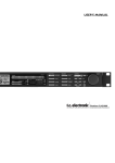
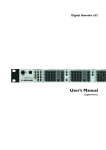
1
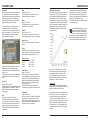
DB2
LOUDNESS CONSISTENCY
PROCESSOR
USER’S MANUAL
IMPORTANT SAFETY INSTRUCTIONS
The lightning flash with an arrowhead
symbol within an equilateral triangle is
intended to alert the user to the presence
of uninsulated “dangerous voltage” within
the product’s enclosure that may be of sufficient
magnitude to constitute a risk of electric shock to
persons.
The exclamation point within an equilateral triangle is intended to alert the user
to the presence of important operating
and maintenance (servicing) instructions
in the literature accompanying the product.
1
2
3
4
5
6
7
Warning!
• To reduce the risk of fire or electrical shock,
do not expose this equipment to dripping or
splashing and ensure that no objects filled
with liquids, such as vases, are placed on the
equipment.
• This apparatus must be earthed.
• Use a three wire grounding type line cord like the one supplied with the product.
• Be advised that different operating voltages
require the use of different types of line cord and attachment plugs.
• Check the voltage in your area and use the correct type. See table below:
Read these instructions.
Keep these instructions.
Heed all warnings.
Follow all instructions.
Do not use this apparatus near water.
Clean only with dry cloth.
Do not block any ventilation openings. Install
in accordance with the manufacturer’s instructions.
8 Do not install near heat sources such as
radiators, heat registers, stoves, or other
apparatus (including amplifiers) that produce
heat.
9 Do not defeat the safety purpose of the polarized or grounding-type plug. A polarized plug has two blades with one wider than the other. A grounding type plug has two blades and a third grounding prong.
The wide blade or the third prong are provided
for your safety. If the provided plug does not
fit into your outlet, consult an electrician for
replacement of the obsolete outlet.
10 Protect the power cord from being walked on or pinched particularly at plugs, convenience receptacles, and the point where they exit from the apparatus.
11 Only use attachments/accessories specified
by the manufacturer.
12 Use only with the cart, stand, tripod,
bracket, or table specified by the
manufacturer, or sold with the
apparatus. When a cart is used, use
caution when moving the cart/apparatus combination to avoid injury from tip-over.
13 Unplug this apparatus during lightning storms
or when unused for long periods of time.
14 Refer all servicing to qualified service personnel. Servicing is required when the apparatus has been damaged in any way, such as power-supply cord or plug is damaged, liquid has been spilled or objects
have fallen into the apparatus, the apparatus has been exposed to rain or moisture, does not operate normally, or has
been dropped.
Voltage Line plug according to standard
110 to 125 V UL817 and CSA C22.2 no 42.
220 to 230 V CEE 7 page VII, SR section
107-2-D1/IEC 83 page C4.
240 V
BS 1363 of 1984.
Specification for 13A fused plugs
and switched and unswitched
socket outlets.
• This equipment should be installed near the
socket outlet, and disconnection of the device
should be easily accessible.
• To completely disconnect from AC mains,
disconnect the power supply cord from the AC
receptacle.
• The mains plug of the power supply shall
remain readily operable.
• Do not install in a confined space.
• Do not open the unit – risk of electric shock
inside!
Caution:
You are cautioned that any change or modifications not expressively approved in this
manual could void your authority to operate this
equipment.
Service
• There are no user-serviceable parts inside.
• All service must be performed by qualified
personnel.
a
IMPORTANT SAFETY INSTRUCTIONS
EMC / EMI.
These limits are designed to provide reasonable protection against harmful interference
in residential installations. This equipment
generates, uses and can radiate radio
frequency energy and, if not installed and used
in accordance with the instructions, may cause
harmful interference to radio communications.
However, there is no guarantee that interference will not occur in a particular installation. If
this equipment does cause harmful interference
to radio or television reception, which can be
determined by turning the equipment off and
on, the user is encouraged to try to correct the
interference by one or more of the following
measures:
•
•
•
•
Reorient or relocate the receiving antenna.
Increase the separation between the equipment and receiver.
Connect the equipment into an outlet on a circuit different from that to which the receiver is connected.
Consult the dealer or an experienced radio/TV technician for help.
For the customers in Canada:
This Class B digital apparatus complies with
Canadian ICES-003.
Cet appareil numérique de la classe B est
conforme à la norme NMB-003 du Canada.
TABLE OF CONTENTS
Important Safety Instructions........................... a
Certificate of Conformity
TC Electronic A/S, Sindalsvej 34, 8240
Risskov, Denmark, hereby declares on own
responsibility that following products:
DB2 – Loudness Consistency Processor
Table Of Contents............................................ 3
Introduction....................................................... 5
Quick Start Guide............................................. 7
Front Panel Overview....................................... 8
Front Panel Overview....................................... 9
Rear Panel..................................................... 10
– that is covered by this certificate and
marked with CE-label conforms with
following standards:
Signal Flow Diagram...................................... 11
EN 60065
(IEC 60065) EN 55103-1 EN 55103-2
The TC Icon Editor......................................... 14
Safety requirements for mains
operated electronic and related apparatus for household and similar general use
Product family standard for audio,video, audio-visual and entertainment lighting control apparatus for professional use. Part 1: Emission.
Product family standard for audio, video, audio-visual and entertainment lighting control apparatus for professional use. Part 2: Immunity.
With reference to regulations in following
directives:
2006/95/EEC, 89/336/EEC
May 2009
Anders Faurskov
Chief Executive Officer
Typical Setups................................................ 12
Installation - Icon Editor.................................. 13
Preset Structure – Recall/Store/Delete.......... 16
Basics – Preset Handling............................... 17
Cloning DB2’s................................................. 18
System – I/O Page......................................... 19
System – I/O Page......................................... 20
GPI................................................................. 21
Front Panel Configuration.............................. 22
System – Net Page & Icon Views.................. 23
I/O Page......................................................... 24
Main Page...................................................... 25
Loudness page............................................... 27
EQ Page......................................................... 29
5-band Page................................................... 32
Limiter............................................................. 34
Appendix........................................................ 35
Troubleshooting.............................................. 36
Technical Specifications................................. 37
DB2 Presets................................................... 38
Self Test......................................................... 41
b
TC Electronic, Sindalsvej 34, DK-8240 Risskov – [email protected]
English Version
Prod. No: 606142012
Rev 3 – SW – V 1.25
3
INTRODUCTION
Introducing DB2
Consistency in loudness levels plus sync of audio to picture: These are the two most important
issues you need to get right in today’s broadcast. They are also two of the reasons why TC Electronic’s DB range of high definition audio processors has set the standard amongst broadcasters
the world over.
DB2 puts all of the tools necessary for trouble-free broadcasting into one rack-mountable unit,
and adds to a scalable family of processors covering every application – from regional stations to
network centers, from podcast to HDTV, from AC3 to linear, and from mono to 5.1.
DB2 is the new smaller brother of DB4 and DB8. It is the perfect choice for dual mono or stereo
operation in MPEG, AAC, AC3 or linear audio transmission and linking. Performance is similar to its
bigger siblings, and is also preset compatible across the range. Like the rest of the DB family, DB2
offers high-quality loudness correction without metadata dependence and is compatible with the
latest ITU and EBU audio standards.
DB2 is compliant with ITU-R BS.1770-2, EBU R128, ATSC A/85, TR-B32 and OP59 and enables
one-pass trickle-down from any of those standards to optimum mobile broadcast.
DTV Step by Step
With the launch of DB2, TC Electronic also introduces a new commitment to buyers of any DB
processor: Within two years of the original purchase, users may upgrade DB2 to DB4 or DB8, and
DB4 to DB8, at only the price difference plus a modest handling cost.
For let’s face it: Nobody knows if your audience will prefer stereo, multiple stereo, multichannel, or
something else – so we want to ensure that you can stay as flexible and as automated as possible
at a minimum entry cost, yet retain a valuable option to upgrade.
The Transparent Loop
TC Electronic is the world’s premier supplier of automatic loudness correction equipment. It
has developed a high quality loudness range trickle-down concept that works independently of
metadata, but is nevertheless fully compliant with meta data in, for instance, the AC3 codec. DB
processors not only automate loudness control in a proper way – they also help take the extra
workload and unpredictable behavior out of the codec.
Applied in ingest and/or transmission, DB processors are part of a transparent loop, based on open
EBU and ITU standards, spanning from production over transmission to delivery at the home. Production can use metering of any brand compliant with these standards, including TC Electronic’s
LM5D radar meter, and obtain predictable results across broadcast platforms. News, soap, commercial, film, music, promo: All genres are covered.
5
INTRODUCTION
The Tools
DB-2 offers broadcasters a wide variety of connection options to ensure simple yet comprehensive
integration into all of the most popular broadcasting systems. DB-2 can also be controlled remotely
with TC’s award-winning Icon software, allowing direct parameter control and preset switching from
any location.
Based on an immensely powerful, low latency topology, DB2 offers a host of 48 bit resolution tools
to be invoked simultaneously:
*
*
*
*
*
*
*
Loudness correction as per ITU-R BS.1770-2
5-band Level Optimization
Online Delay Adjustment
Adaptive Limiting
Emphasis Compensation
Filtering and EQ
Stereo Width Adjustment
The Connections
Audio I/O include 24 bit AES3-id on BNC connectors and balanced analog on XLR connectors with
analog domain gain scaling. Digital as well as analog inputs and outputs feature hardware bypass.
Remote control may be established via RS232, USB and/or GPI, and SNMP signaling is available
via the Icon application.
About this manual
The latest manual revision can always be downloaded from www.tcelectronic.com
If you have questions that are not answered by this manual, you may want to use our TC Support
Interactive site. This site is also accessed via www.tcelectronic.com
6
QUICK START GUIDE
Quick Guide
Requirements
One DB2 Loudness Consistency Processor and
a computer with an Intel Pentium (or better)
processor and Windows 95, 98, NT, 2000, ME
or XP installed.
Installation of TC Icon Editor Software
Enter the CD, open it, run Setup.exe and follow
the instructions shown on-screen.
Connecting DB2
• Connect the RS232 In port of the DB2 to a
COM port on your PC. If there are several
COM ports, note to which port you have
connected the DB2.
(The supplied RS232-to-USB connector can
be used to connect the DB2 to a computer’s
USB port. However, note that where RS232
can carry signal over cable lengths of up to
200 meters, USB cable lengths should not
exceed 10 meters.)
• Programming the DB2 does not necessarily
require audio to be connected. However, if
audio connections are needed, make audio
connections according to the setup illustrations in this manual.
Getting started with the TC Icon Editor
• Power up the DB2 and start the TC Icon
software on your computer.
• Go to the Setup / Devices / Port page to
select which COM (1 to 4) port you have
connected the DB2 (per default, the Editor
will look at COM ports 1 to 4 automatically).
• Go to the Setup / Devices / Select page.
Click DETECT and assign the detected DB2
to one of the eight device locations in the
right side of the display. To do so, simply
click any of the eight buttons.
• Click the ICON button in the upper left corner
to go the pages from where all local DB2
parameters are controlled.
Library Page: handles presets
System Page: handles Clock, Level trims,
Lock functions and the variable yellow LED
Threshold.
Engine: All algorithm parameters.
Cloning DB2’s using a PCMCIA card
Once a single DB2 has been set up for the
desired applications, other DB2’s in the house
can be easily cloned using a standard PCMCIA
card. In other words; it is NOT necessary to
hook up every single DB2 to a computer to set
these up.
• Insert an unprotected PCMCIA card into the
source DB2’s card slot.
• Go to the TC Icon System/Card page.
• Decide whether you wish to exclude the
System Preset that hold overall Clock
settings, Analog Trim levels, Dither, Status
Bit settings and GPI settings. To exclude the
System Preset, activate the “Exclude System
Preset” button.
Then click CREATE CLONE CARD.
•
•
•
•
ALL DATA previously stored on the card
will be destroyed when formatting the
card! If the card is write-protected, no
data can be written on the card. The
protect/unprotect switch is located at the
edge of the card.
Remove the card and go to the target DB2
unit.
Power off the target DB2 unit.
Insert the card and power up using the front
panel POWER key while holding the OK key
pressed. Press UTILITY until the display
shows “C” (CLONE).
Now press the OK key. All settings (with or
without “System Preset”, depending on your
previous selection) are now copied to the
target DB2.
7
FRONT PANEL OVERVIEW
POWER On/Off
Switches power On/Off.
To completely disconnect from
mains, the Rear panel POWER
switch must be used.
PCMCIA Slot
For software updates and
preset backups.
ERROR LED
Indicates various error states,
e.g. signal overflow, digital
input or sync lost.
48/44.1/32 kHz LEDs
Indicates output sample rate.
Note that input sample rate
may be different when DB2’s
sample rate converter is
engaged. A blinking sample
rate LED indicates a sync
error, e.g. that a digital input is
unavailable.
GAIN Meter
Indicates the current Loudness
correction gain as per ITU-R
BS.1770 or ITU-R BS.1770-2.
OPTIMIZE Meters
Indicates gain reduction in the
5-band processor.
When Utility is activated,
this section is used for alpha
numerical display.
LIMIT Meter
Indicates gain reduction of the
output true-peak limiter.
FRONT PANEL OVERVIEW
INPUT/OUTPUT Meters
• The Input meters indicate
the level of the Input signal
after the In Gain control
(set via the TC Icon control
interface).
• The Output meters indicate
the current Output level.
UTILITY & OK Keys
The UTILITY and OK keys are used for
software version check and access to Reset
and Software Load menus – see appendix for
details.
These keys do not disturb operation, and
may be used while the unit is on-air.
• Threshold value for meter
color change:
For both Input/Output
meters: Below -20 dB
the meter LEDs are green.
From -20 dB to 0 dB LED
color can be green or
yellow.
The value for this color
change is set via the TC
Icon Editor on the System
Front page.
ANALOG IN/DIGITAL IN
Indicates currently selected
input type. In case digital input
is lost, the Analog In LED
blinks to show that the unit has
switched to analog input for
redundancy purposes.
DUAL MONO LED
Indicates that the DB2 is
operating in Dual mono mode.
EDITED LED
Indicates that the currently
recalled preset has been
edited but not stored.
8
9
REAR PANEL
Power Input
100 to 240V
Power Switch
Balanced
Analog
Inputs
XLR
SIGNAL FLOW DIAGRAM
Balanced
Analog
Outputs
XLR
GPI IN
AES3-id S/PDIF RS 232
Input/ 9 pin Sub D
Input/
Output
Output
RS232:
For connecting to a PC RS232 port, use a standard 9 pin Sub D cable. (Supplied)
For connecting to a PC USB port, use the supplied RS232 to USB connector
(Note max recommended USB cable length 10 m, while the RS232 part of the cable
may be much longer)
GPI In:
Use standard stereo ¼” jack. (not supplied)
SYNC:
Use standard shielded 75 Ohm Coax cable with BNC connectors (not supplied).
XLR to XLR
10
BNC
Sync In
XLR to Jack
Stereo
11
TYPICAL SETUPS
INSTALLATION - ICON EDITOR
Connecting and Setting up the DB2
In use – no TC Icon Editor/PC connection
necessary.
• Connect your audio source material to DB2
Inputs. Options are balanced Analog, digital
AES3-id or S/PDIF.
• Connect Outputs to relevant media.
Standard Setup
• Connect a free RS232 serial COM port on
the computer to the RS232 connection on the
rear of DB2. Use the supplied RS232 to USB
connector when connecting to USB.
(Note max. verified USB cable length is 10 m)
• Start the TC Icon PC Editor and select appropriate COM port.
(Read TC Icon installation procedure section)
Make audio connections if these are necessary
for programming.
Cloning DB2’s using a PCMCIA card
Once a single DB2 has been set up for the
desired applications, other DB2’s in the house
can be easily cloned using a standard PCMCIA
card. In other words; it is NOT necessary to
hook up every single DB2 to a computer to set
these up.
• Insert an unprotected PCMCIA card into the
source DB2’s card slot.
• Go to the TC Icon System/Card page.
• Decide whether you wish to exclude the
System Preset that hold overall Clock
settings, Analog Trim levels, Dither, Status
Bit settings and GPI settings. To exclude the
System Preset, activate the “Exclude System
Preset” button.
Then click CREATE CLONE CARD.
12
•
•
•
•
ALL DATA previously stored on the card
will be destroyed when formatting the
card! If the card is write-protected, no
data can be written on the card. The
protect/unprotect switch is located at the
edge of the card.
Remove the card and go to the target DB2
unit.
Power off the target DB2 unit.
Insert the card and power up using the front
panel POWER key while holding the OK key
pressed. Press UTILITY until the display
shows “C” (CLONE).
Now press the OK key. All settings (with or
without “System Preset”, depending on your
previous selection) are now copied to the
target DB2.
Requirements for running the TC Icon
Software Editor
• A PC with a Pentium or compatible processor
with one of the following operating systems:
Windows 95, Windows 98, Windows NT,
Windows 2000, Windows ME, Windows XP
and Windows Vista.
Problems?
If during the process described above you
have discovered that the required MS Installer
program is NOT already installed on your
computer, you should run the installation file
including the MS installer: TC Icon x.xx.zip
This file is located in the folder called:
The CD-ROM
The CD-ROM delivered with the TC Icon
Software Editor contains:
• A folder called “TC Icon Software Editor –
Update version“. Use the contents of this
folder if the MS Installer* has already been
installed on your computer.
• A folder called “TC Icon Software Editor +
MS Installer” (use the contents of this folder
if MS Installer has not been installed on your
computer – see below)
• The DB2 Manual in PDF format.
TC Icon Software Editor + Microsoft Installer.
Installing
the TC Icon Software Editor
Your computer probably holds the required MS
Installer program and you only need to run the
file called: TC Icon x.xx.msi
This file is located on the CD in the folder
called: “TC Icon Software Editor – Update Version”
• Exit all programs currently running on your
computer and open the CD contents in
Windows Explorer.
• Open the folder called “TC Icon Software
Editor – Update Version”.
• Copy the file called “TC Icon x.xx.msi” to a
location on your computer’s hard drive.
• Double-click the icon and follow the instructions.
A “TC Icon” shortcut will appear both on the
desktop and in the Start menu.
This file includes both the Microsoft Installer
Service and the TC Icon Software Editor.
• Exit all programs currently running on your
computer and open the CD contents in
Windows Explorer.
• Open the folder “TC Icon Software Editor +
MS Installer” and double-click on “TC Icon
x.xx.zip”.
• Select a location to unzip the files to.
“Windows/Temp” is automatically suggested.
• Click FINISH.
• Restart your computer when prompted to.
• After restart, the installation of the TC Icon
Software Editor will proceed.
• Follow the instructions.
A “TC Icon” shortcut will appear both on the
desktop and in the Start menu.
* The MS installer is a small installation program by Microsoft
which is required to run a regular .msi-update. The program is
installed on most computers running Windows 98 SE and up.
DB2 needs Icon software 4.01 or higher
for correct operation
13
THE TC ICON EDITOR
THE TC ICON EDITOR
Introduction
The TC Icon Software Editor is a generic editor
that currently controls the following products
by TC Electronic: System 6000, DB-8/DB-4/
P2/Reverb4000 and DB2. In this section only
subjects relevant for usage with the DB2 will be
discussed.
DB2 is connected to your computer via a serial
COM port (RS232) or via the supplied RS232to-USB converter.
Another active application may access
the selected COM Port, resulting in a
conflict. If this is the case, you should
close that application or connect the DB2 to
another COM port. Also see this manual’s
“Troubleshooting” section.
Basic Operation
The Icon Link button in the upper left corner
allows you to navigate between two main
pages/modes.
Fig 1 – Setup/Select Page
• Go to the TC Icon Setup/Devices page.
System pages handle overall clock settings, I/O
settings and network settings.
Engine pages allow you to control all algorithmspecific processing parameters.
Renaming Presets
All user presets can easily be renamed.
Click on the CURRENT ENGINE NAME button
on the Store page. A keyboard display will open.
Please note that RS232 can be used
over long distances (up to 200 meters),
whereas the cable length should not
exceed 10 meters when the RS232 to
USB converter is used.
Navigating the Software Editor or TC Icon
display is easy once you have grasped the
basic concepts explained in the following
section.
Basics:
• Click the top tabs to make primary selections.
• Click the side tabs or elements to make
secondary selections.
• On the Setup/UI page select either “Faders
at bottom” or “Fader at Right Side”.
• Click on parameter value fields to instantly
assign parameters to Fader 6.
• Adjust values using Faders 1 to 6. (Also see
the explanation of LINK on next page.)
Unpacked and ready
• Connect the DB2 according to the illustrations on page 12.
• Install the software according to the explanations on the previous page of this manual.
• Power up DB2 and start the TC Icon
software on your computer.
• Go to the Setup/Devices/Ports page to select
the COM port (1 to 4) to which you have
connected the DB2.
• Click the DETECT button. The TC Icon Editor
will scan the System and find the connected
DB2’s.
• When the connected DB2 is detected,
assign the unit to one of the eight shortcut
buttons on the right side of the display by
clicking one of the eight buttons (see above).
Any button will do. When several units are
connected, this page serves as a convenient
organizer for the entire system.
• Go to the Select page (top tab), and you will
see a screen similar to the one below. The
number of connected units and their locations
may vary depending on your specific setup.
Via the “overall” Select & Setup pages
you can access overall settings and make
choices such as:
• Selecting which of the connected units you
want to operate.
• Enabling devices for networking.
• Making TC Icon settings (such as display and
fader appearance).
On the Select page shown above (Fig. 1), all
connected units will appear. Click on one of the
units shown on that page.
Auto Page
This page is not required for operating a DB2.
Fig 2 – Operating pages
• Click the large DB2 button.
• TC Icon now retrieves data from the DB2.
• When ready you will see the Main operating
display.
• Select the correct port. (Note that when you
open the Setup Port page for the first time,
all COM ports – 1 to 4 – are selected).
14
Click the Icon Link button in the upper left
corner to select these pages.
These pages are relevant to one specific unit.
Library pages handle operations such as
recalling, storing and deleting presets.
Please note that entering the name and
pressing ENTER does not permanently
store the new name. To actually store
a preset, you have to click the STORE
button on the Store page.
Fader Assign
The Fader Assign button allows you to assign
any algorithm parameter to any of the six
Faders. This means that you are not limited to
operating the parameters visible on the current
page. You can have e.g. the In Gain parameter
from the Main page assigned to Fader 1, the
Loudness Level Trim from the Loudness page
assigned to Fader 2 etc.
To assign a parameter:
• Click the Fader Assign button.
• Select the Fader you wish to link a parameter
to by clicking the field just above the fader.
• Click the parameter you wish to link to the
selected fader.
15
PRESET STRUCTURE – RECALL/STORE/DELETE
Library Pages
On these pages, all preset operations are
handled.
BASICS – PRESET HANDLING
Engine Presets
Bank Handling
Via the Library Bank page, you can:
• Backup and retrieve the System User bank.
• Backup and retrieve any user bank (U1 to
U8) to any user bank location (U1 to U8) or
to your hard disk.
Engine presets hold all parameters and settings
from the Engine page.
To recall a preset:
• Simply select the desired preset by clicking
on the preset name in the list.
• Then click the RECALL button.
Preset List
Recall button
User Presets
The User banks U1 to U8 can hold up to eight
presets each.
To delete a preset:
• Select the Delete page by clicking the
DELETE side tab.
• Select the preset you wish to delete.
• Click DELETE.
From Bank
On this page you select which bank on the DB2
you wish to copy from.
Factory Presets
DB2 comes loaded from the factory with a
collection of general purpose factory presets,
organized in banks F1 to F8.
System Presets:
There are three System User memory locations
and one Factory Default. None of them is
affected by regular Recall operations.
System User memory 1 is always recalled
when powering up the unit.
System presets include:
Analog Trim, Meters, Dither, Remote and
Bypass settings.
System parameters are described later in this
manual.
16
From File
If you have already stored banks on your
computer, this is where the files will appear.
Store – Delete
To store a preset:
• Select the Store page by clicking the STORE
side tab.
• Select a preset location.
• Click STORE.
When Presets are stored or deleted, parameters on the In/Out page and Engine Layers are
always affected.
System parameters, on the other hand, are
unaffected by any other commands than a
specific System Store or System Delete.
To Bank
Select which DB2 bank you wish to copy the
selected bank to.
To File
Select “To File” if you wish to backup the
selected bank to your hard disk.
The TC Icon saves the bank files in a
specific location. This location varies
slightly between different operating
systems.
As an example, Windows 2000 saves backup
files in Application Data\TC Electronic\TC Icon\
DB2 Presets\xxxxx
Do not move the files from this location, or the
TC Icon will not be able to display the presets
on the “From File” page.
17
CLONING DB2’S
Cloning DB2s
Cloning DB2’s using a PCMCIA card
Once a single DB2 has been set up for the
desired applications, other DB2’s in the house
can be easily cloned using a standard PCMCIA
card. In other words; it is NOT necessary to
hook up every single DB2 to a computer to set
these up.
• Insert an unprotected PCMCIA card into the
source DB2’s card slot.
• Go to the TC Icon System/Card page.
• Decide whether you wish to exclude the
System Preset that hold overall Clock
settings, Analog Trim levels, Dither, Status
Bit settings and GPI settings. To exclude the
System Preset, activate the “Exclude System
Preset” button.
Then click CREATE CLONE CARD.
•
•
•
•
ALL DATA previously stored on the card
will be destroyed when formatting the
card! If the card is write-protected, no
data can be written on the card. The
protect/unprotect switch is located at the
edge of the card.
Remove the card and go to the target DB2
unit.
Power off the target DB2 unit.
Insert the card and power up using the front
panel POWER key while holding the OK key
pressed. Press UTILITY until the display
shows “C” (CLONE).
Now press the OK key. All settings (with or
without “System Preset”, depending on your
previous selection) are now copied to the
target DB2.
SYSTEM – I/O PAGE
Bypass and Redundancy
DB2 includes hardware bypass on its analog as
well as AES3-id inputs and outputs.
Output Trim L & Output Trim R
Range: +1.00 to -1.00 dB in 0.05 dB increments
Level trim for analog outputs.
When selected, the unit furthermore constantly
monitors its digital inputs for signal integrity.
If the digital input is lost, automatic input
redundancy switching is invoked. In this case,
DB2 switches to internal 48 kHz sample rate
operation and analog inputs.
Digital Output
Redundancy alarm is indicated by the 48 kHz
and Analog In LEDs blinking and the ERROR
LED lit. Once the digital input is reestablished,
DB2 reverts to normal operation and clears the
alarm.
Dither
Range: 8, 12, 14, 16, 18, 20, 22, 24, off
DB2 processes audio signals internally at 48 bit
resolution. Dither must be set to match downstream devices.
Parameters on the System page can be
stored and recalled via System presets and
are unaffected by normal Recall operations.
Clock Preferences
Analog
Range: Internal 44.1 kHz
Internal 48 kHz
Ext. W. Clk. (External Word Clock)
Ext. DI
Sets the processing clock frequency to be used
when analog inputs are used.
Digital
Range: Internal 44.1 kHz
Internal 48 kHz
Ext W Clk (External Word Clock)
Ext. DI
Sets processing clock frequency to be used
when processing signal from the AES or S/
PDIF input.
Digital w. SRC
Range: Internal 44.1 kHz
Internal 48 kHz
Ext Word Clock
Sets the processing clock frequency to be used
when Digital SRC is selected on the Engine I/O
page.
Analog Trim
Input Trim L & Input Trim R
Range: +1.00 to -1.00 dB in 0.05 dB increments
Level trim for analog inputs.
18
Status Bits
Select whether the DB2 should send out AES/
EBU or S/PDIF status bit information.
GPI
The GPI input reads the analog DC level fed
to this port, and may be assigned to a variety
of functions: It may set the output level, add
or change the on-line delay, enter and exit
bypass, and make DB2 switch between up to 8
presets.
GPI Assign
Disabled
The device connected to the GPI port is disregarded.
Fader
Select this setting to enable GPI control of
DB2’s output gain. The DC level on the tip of
the connector is read and used to adjust the
output gain (“Output Fader” on the Engine/
Limit page). Inside DB2, a 10 kOhm resistor
is connected between +5 V and the tip of the
GPI jack. Therefore, a passive external fader or
potentiometer can be used to control the output
gain. Use the Calibration function to optimize
the control range for a given pot.
Bypass
Select this setting to enable bypassing DB2
using an external switch. Note that you may
accidentally put DB2 to bypass mode when
selecting between the GPI settings. The Bypass
function is defined on the System/Front page.
19
off
off
on
on
RL2
GPI Implementation
GPI Implementation
SYSTEM – I/O PAGE
Delay
Select this setting to enable online adjustment
of delay (e.g. for lip-sync) using an external
switch or impulse relay. DB2 measures the
time interval between two switch closures, and
inserts this as its current delay.
(The “Delay” parameter on the Engine/Main
page has a range from 0 to 1000 ms). Thanks
to a silent update mechanism, the delay may
be adjusted while audio is passed through the
processor without introducing pitch change or
click noise.
Calibrate
Nov 1, 2002
Three modes...
Three modes...
1 of 2: Select between 2 presets
1 of 2: Select between
2 presets
1 of 4: Select
between 4 presets
1 of 4: Select between
4 presets
1 of 8: Select
between 8 presets
1 of 8: Select between 8 presets
RL1
vers #1.30
The ring terminal of the ¼” jack is not
used.
If
GPI Preset mode is selected and no device is
connected to the GPI input, the DB2 will always
recall preset 1 at power up.
20
R2, 22k
vers #1.30
RL1
off
on
tip
nc
ring
nc
sleeve
RL1
off
preset 1on
preset 2
tip
GPI Input
ring
Select 1 of 2
sleeve
GPI Input
Select 1 of 2
RL3
R3, 47k
RL2
R2, 22k
R1, 12k
RL1
R1, 12k
Use this function to calibrate DB2 to a
connected GPI controller (e.g. master control
relays or a potentiometer such as the TC Master
Fader).
To calibrate the GPI controller:
• Connect the GPI Controller to the GPI Input
jack and click CALIBRATE.
• Set the GPI controller to its minimum position
and click “Set Lo Threshold”.
• Set the GPI controller to its maximum position
and click “Set Hi Threshold”.
• Press OK to complete the calibration
procedure.
GPI Current voltage:
Indicates the current voltage on the GPI Input.
With no GPI controller connected, the voltage is
1000 mV. Therefore it is worth noticing that the
maximum indicated value on e.g. Master Fader
is a lower voltage value than the minimum
value.
Select 1 of 4
preset 1
preset 2
R2, 22k
RL2
R2, 22k
GPI
GPI Input
ring
nc
preset 1
preset 2
preset 3
preset 4
sleeve
RL1
RL2
off
off
on
on
RL2
tip
RL1
R1, 12k
RL1
off
on
off
on
tip
RL1
nc
ring
nc
sleeve
Preset
Range: 2 presets, 4 presets or 8 presets
Selection between up to 8 presets is achieved
by feeding the processor a DC voltage to its
¼” jack input. The Input voltage is compared
against voltage windows that correspond to
certain presets.
Between the valid voltage windows, invalid
windows have been inserted to protect against
erratic operation. The processor constantly
monitors the GPI input, and only if several consecutive measurements point to the same, valid
voltage window, a recall is performed.
The voltage windows chosen enable easy
“binary relay encoding” as shown on the next
page in fig. 1. If long cable runs are required,
HF decoupling using a ceramic capacitor
across the tip and sleeve terminals inside the
jack plug may be indicated.
Nov 1, 2002
off
on
off
on
RL2
RL1
off
off
off preset 1on
on preset 2off
preset
3on
on
preset 4
tip
GPI Input
ring
Select 1 of 4
sleeve
preset 1
preset 2
preset 3
preset 4
RL3
off
off
off
off
on
on
on
on
RL2
off
off
on
on
off
off
on
on
tip
RL1
R1, 12k
RL1
off
on
off
on
off
on
off
on
nc
ring
preset 1
preset 2
preset 3
preset 4
preset 5
preset 6
preset 7
preset 8
GPI Input
Select 1 of 8
sleeve
GPI Input
Select 1 of 4
GPI Technical Specifications
Inside the processor, a RL3
10 kOhm
resistor
connects the tip terminal to a +5 V power supply. When
RL2
RL1
RL3
RL2 off RL1 off
off
preset 1
off
off the
1on
nothing is connected
to
input,
the
voltage therefore is +5 V. Resistors can be used to
off offGPI
off preset
presetinput
2
RL3 off
off off on on preset 2off
RL3
preset 3
off
on
off on preset 3onin Fig
pull down
the voltage
asoffsuggested
preset1.
4
R3, 47k
off
on on on off preset 4off
R3, 47k
preset 5
on
off on off off preset 5on
preset 6
In Table 1, voltages
outside
limits mentioned
are to be considered invalid. No action is taken
off on on the
on preset 6off
preset 7
RL2 on
on
on on off on preset 7on
RL2
preset
8
if
invalid
measurements
are
made.
GPI
recall
action resumes when a stable, valid measurement
on
on
on
preset
8
R2, 22k
R2, 22k
again is detected.
tip
tip
R1, 12k
RL1
R1, 12k
Mode
RL1
nc
ring
nc
sleeve
GPI Input
ring
Select 1 of 8
sleeve
GPI Input
Select 1 of 8
Preset No
Target / Vs
Min typ / V
Target typ / V
Max typ / V
1
2
1.000
0.000
2.67
0.00
5.00
0.00
5.00
0.51
1
2
3
4
1.000
0.687
0.545
0.438
4.16
3.38
2.67
0.00
5.00
3.44
2.73
2.19
5.00
3.50
2.79
2.25
1
2
3
4
5
6
7
8
1.000
0.824
0.687
0.600
0.545
0.489
0.437
0.400
4.50
4.06
3.38
2.94
2.67
2.38
2.13
0.00
5.00
4.12
3.44
3.00
2.73
2.44
2.19
2.00
5.00
4.18
3.50
3.06
2.79
2.50
2.25
2.06
1 of 2
1 of 4
1 of 8
Rather than absolute voltage measurements, the windows are defined as a fraction of the
supply voltage, Vs. This voltage can be measured with a high impedance DMM on the Tip
terminal when no pull down resistors are applied. The table shows values as a fraction of Vs,
and, as a guideline, typical voltages when Vs = 5.000 V. (If the supply voltage is e.g. 5.015 V,
the table should be corrected by multiplying these values by 5.015/5).
21
FRONT PANEL CONFIGURATION
SYSTEM – NET PAGE & ICON VIEWS
Fader at right side
Bypass Configuration
Press the round BYPASS button to activate.
Normal:
No Delay in bypass and
Dithering is active.
Relay:
Bit-transparent digital and
analog Bypass Relay.
No Codec Delay: No delay in bypass.
Bypass bit transparency.
Codec Delay:
Delay active in Bypass.
Bypass bit transparency.
Yellow LED Threshold
Analog In, Analog Out & Out Threshold
Range: 0 to 20 dB
Use this parameter to set the response
threshold for the two yellow digits on the In/Out
meters.
The upper part of this page holds information
on the current software versions and the serial
number of the accessed unit.
No Faders
Network Identification
This is a simple naming function that enables
you to name each connected unit.
UI – Icon Views
On the Icon Setup page, two sub-pages are
available for controlling the TC Icon software’s appearance.
Fader Appearance
Three options are available. Changes will take
place next time you open the TC Icon.
Faders at bottom
Color Page
Use this page to select a color scheme you like
or to create your own.
22
23
I/O PAGE
MAIN PAGE
Analog Levels
Analog Scale
Range: -3 to +27 dBu @ Full scale
Use this parameter to set the sensitivity of the
analog input.
Analog In Offset
Range: -3 to +25 dBu @ Full scale
Use this parameter to set the analog input
level.
Input & Clock
Input Select
Range: Analog, Digital
Use this parameter to select the appropriate
input type.
Analog Out Offset
Range: -3 to +24 dBu @ Full scale
Use this parameter to match the analog output
gain to the following (“downstream”) device.
Digital Level
Digital Out Offset
Range: -12 dB to 0 dB
The Digital Out Offset parameter controls the
digital output level in accordance to the set
Analog Scale Output level.
Input
Filter
In Gain
Range: 0 dB to Off
There are separate level controls for the left
and right Input (A and B).
Lo Cut
Range: Off to 200 Hz
This is a second order LoCut filter on both
inputs.
Clock Select
Range: Internal 44.1, Internal 48k, Word Clock,
Ext DI
Use this parameter to select the output sample
rate.
Phase Inv L/R
Range: Normal/Inverted
Click to invert the phase of channels L, R, or
both.
Hi Cut
Range: Off to 3 kHz
This is an 8th order HiCut filter on both inputs.
Digital SRC
Range: On/Off
For optimum performance, establish a synchronous signal-path. Sample rate conversion
reduces the dynamic range a bit and adds
latency.
Delay
Range: 0 to 1000 ms
Use this parameter for delay alignment of the
input channels. Depending on the selected
configuration type, either one common Delay
setting or individual delay settings are available.
Digital Input Select
Range: AES3-id, S/PDIF
Use this parameter to select the digital input
format.
Delay Unit
Range: ms, 24 fps, 25 fps, 30 fps
Use this parameter to select which unit should
be used to display the Delay parameter. Please
note that changing this parameter does not
affect the actual delay time.
24
Setup
Look-ahead Dly
Range: 0 to 15 ms
If the 5-band compression sections is set to use
very short Attack times (up to approximately 10
to 15 ms), overshoots may occur. The Lookahead function allows the DB2 to evaluate
the material just before processing. This way,
artifacts can be prevented.
Be aware that the Look-ahead delay function
actually delays the output signal.
25
MAIN PAGE
MAIN PAGE
Configuration
Configuration
LOUDNESS PAGE
– Stereo: In this mode, the Loudness, EQ
and Multiband sections operate in tandem:
Whatever gain change is applied to one
channel, is applied to the other. Also, many
parameters have mutual left and right
controls.
Processing Overview
– Dual Mono: In this mode, the Loudness, EQ
and Multiband sections treat the two Input
signals completely independently.
– Stereo Wide: In this mode, the apparent
width and image of stereo signal can be
altered simultaneously with controlling
loudness and peak level. The left and right
signal is internally de-composed into an M
(= Mono) and S (Stereo) component, and
reverted to left and right signals before peak
limiting on the Output.
– Sum Mono: Left and right channels are
summed after Delay, Filters and AGC.
Reference Level
Reference Level defines the standard operating
level, and scales the Threshold and Target
Level parameters of the Loudness control and
Multiband section accordingly. The Threshold of
the Limiter is not influenced by this setting, but
is always relative to 0 dBFS.
Analog vs. Digital level
If you use analog interfacing, remember to
always define the relationship between absolute
analog and digital level before adjusting parameters in the Engines.
Typical analog I/O level scaling would be +24
dBu in the Americas and some parts of Asia,
and +18 dBu in Europe, Japan and some parts
of Asia.
Note 1: Be careful when switching between
configurations. Going from Dual Mono to Stereo
will result in parameter settings of the left (or
“A”) channel being copied to the right (or “B”)
channel. Going from Dual Mono to Stereo and
back to Dual Mono will therefore overwrite the
original settings for the right channel (or “B”
channel)!
26
Note 2: In all configuration modes, linking of
the Brickwall Limiter is set separately on the
Limiter page. Some broadcasters like the sound
of operating left and right limiting without stereo
coupling because they feel that it maximizes
loudness and widens the stereo image.
On dual mono sources, of course you should
always choose un-linked Limiter operation.
– Left Mono: Only the left channel is being
processed.
– Right Mono: Only the right channel is being
processed.
Target Level
Range: +10 dB to -10 dB
This is the level the Loudness controller will
aim at. Target Level is relative to Reference
Level on the Main Page. Add Target Level
to Reference Level to calculate the target
loudness level. When Loudness Measure is set
to BS.1770-2, the calculation will have the unit
“LUFS”, also known as “LKFS”.
Example: When using the BS.1770-2 measure,
with Reference Level at -20 dBFS and Target
Level at -1 dB, the loudness section of DB2
targets a loudness of -21 LUFS (the same as
-21 LKFS).
Max Reduction
Range: -20 dB to 0 dB
This is the maximum attenuation the Loudness
Control is allowed to perform. If set to 0.0 dB,
the Loudness Control cannot attenuate the
signal at all. The level diagram on the next
page is shown with Max Reduction set at 0.0
dB.
Max Gain
Range: 0 to +20 dB
This is the maximum gain the Loudness Control
is allowed to perform. If set to 0.0 dB, the
Loudness Control cannot add gain to the signal
at all.
27
LOUDNESS PAGE
Freeze Level
Range: -10 dB to -40 dB
Use this parameter to set the minimum level
required before the Loudness Control will start
adding more gain. It would typically be set
to avoid boosting signals considered noise.
The Freeze Level parameter is relative to the
Reference Level setting on the Main page.
EQ PAGE
Level Trim
Range: -18 dB to + 18 dB
Because DB2 internally operates with 48 bit
precision on all audio signals, it is possible
to correct loudness manually without the risk
of overloads. The Level Trim can be used for
permanent offsets or live loudness adjustments.
EQ Page
Freeze Hold
Range: 0 to 5 seconds
When the input signal drops below the Freeze
Level, the Gain Correction of the Loudness
Section is frozen for the period you set with the
Hold parameter. When the Hold period expires,
the Gain Correction falls back to 0 dB gain.
Introduction
DB2 features a digital three-band parametric
EQ with high-pass and low-pass filters switchable between Notch, Parametric, Shelving and
Cut types. The needle-sharp notch filter has a
range down to 0.01 octave, and the shelving
filters has a variable slope, ranging from gentle
3 dB/oct. over 6 and 9 to 12 dB/oct. Cut filters
can be switched between 12 dB/oct. maximum
flat amplitude (Butterworth) or flat group delay
(Bessel) types. The parametric equalizer
features a natural and well-defined bandwidth
behavior at all gain and width settings.
Type Selector
• Click TYPE and use faders 1 to 3 to select
filter types.
For Lo and Hi filters, you can select between
these filter types:
Parametric, Notch, Shelve and Cut.
For the Mid filter, select between these filter
types:
Parametric and Notch.
Basic Operation
• Click the Lo, Mid and Hi buttons to activate/
deactivate the EQ bands.
• Select Freq, Gain, Type or Lo/Hi to access
all four parameters on individual bands.
• Click BYPASS EQ to bypass all three bands.
28
29
EQ PAGE
Parametric Filter – Broad Type
EQ PAGE
Cut Filter – Bessel Type
Type
Click TYPE and use Faders 1 to 3 to set the
BW value for each of the three EQ bands.
Range for the Notch filter:
Lo BW:
0.02 oct. to 1 oct.
Mid BW:
0.02 oct. to 1 oct.
Hi BW:
0.02 oct. to 1 oct.
Range for the Parametric filter:
Lo BW:
0.1 oct. to 4 oct.
Mid BW:
0.1 oct. to 4 oct.
Hi BW:
0.1 oct. to 4 oct.
Shelving Filter
Cut Filter – Butterworth Type
Range for the Shelving filter:
Lo BW:
3 dB/oct. to 12 dB/oct.
Hi BW:
3 dB/oct. to 12 dB/oct.
Range for the Cut filter:
Lo BW:
Bessel or Butterworth
Hi BW:
Bessel or Butterworth
Bandwidth/Q – Key-Values:
BW
Q
0.5
–
2.87
0.7
–
2.04
1.0
–
1.41
Notch Filter – Narrow Type
Freq
Click FREQ and use Faders 1 to 3 to adjust the
frequency for each of the three bands.
Range – Lo band:
Range – Mid band:
Range – Hi band:
20 Hz to 20 kHz
20 Hz to 20 kHz
20 Hz to 40 kHz
Gain
Click GAIN and use Faders 1 to 3 to adjust
gain for each of the three EQ bands.
Range for Parametric, Shelve and Cut types:
Lo Gain:
-12 dB to +12 dB
Mid Gain:
-12 dB to +12 dB
Hi Gain:
-12 dB to +12 dB
Range for the Notch filter:
Lo Gain:
-100 dB to 0 dB
Mid Gain:
-100 dB to 0 dB
Hi Gain:
-100 dB to 0 dB
30
31
5-BAND PAGE
Introduction
Multi-band processing can be used for evening
out spectral differences between programs,
optimizing levels and/or assisting the loudness
correction when changes in loudness occur
suddenly. Make your settings on the 5-band
pages according to the task at hand.
The 5-band processor in DB2 may be used
simultaneously with all other processing
modules. The section may be switched to four,
three or two bands or to “DXP” mode, which
lifts low-level signals instead of performing
regular multi-band compression.
5-BAND PAGE
Ratio
Range: Off to Infinity
Use this parameter to set the ratio for each
frequency band in the compressor.
Attack
Range: 0.3 to 250 ms
Use this parameter to set the attack time for
each band of the compressor.
Release
Range: 20 ms to 7 sec.
Use this parameter to set the time it takes for
each compressor band to recover to unity gain.
DXP Mode – Introduction
The 5-band section works either in normal compression mode or in DXP (“Detail Expansion”)
mode. Instead of attenuating signals above a
certain threshold, DXP mode lifts up signals
that are below the Threshold; thereby bringing
out details rather than squashing the loud parts.
DXP mode therefore is capable of adding intelligibility and air to speech, lifting harmonics,
or emphasizing ambience without increasing
overall peak level.
Bypass Comp.
Click to this button to bypass the 5-band compressor.
Try setting the Steer and/or Threshold parameters differently in the bands to hear the effect.
High Steer values add more detail gain than
low values, but remember that Threshold has to
be negative to add detail gain at all.
DXP Threshold relates to the Reference Level
set on the Main page.
To disable DXP detail gain at very low
levels, use the Defeat Threshold and
Defeat Ratio controls. Defeat threshold
relates to the DXP threshold, and allows
for a certain level-window, inside which detail
gain is applied. Defeat Ratio determines the
slope at which DXP detail gain is defeated.
Xovers
Click this button to access the four cross-over
points between the five bands. The parameters
are automatically assigned to faders 1 to 4.
Pressing Threshold, Range, Ratio, Attack and
Release buttons will immediately assign Lo,
Mid, Hi and All values for these parameters to
Faders 1 to 6.
The “All” parameter offers a relative adjustment
of all bands. Its value reflects that of the Mid
band.
Threshold
Range: -25 dB to +20 dB
Use this parameter to set the threshold for each
frequency band in the compressor. Values are
relative to the Reference Level parameter on
the Main page.
Gain
Range: 0.0 to 18 dB in 0.1 dB steps.
Use this parameter to apply make-up gain to
each frequency band. The gain is reflected on
the 5-band meter on the Icon remote, thereby
giving an idea of the frequency response of
DB2 when levels are below the threshold of
compression.
32
Parameter Range:
Xover 1:
Off to 1.6 kHz
Xover 2:
Off to 4 kHz
Xover 3:
100 Hz to Off
Xover 4:
250 Hz to Off
Defeat Thresh
Range: -3 to -30 dB
This is a unique control which defeats gain
from the multiband compressor below a certain
threshold. No matter what spectral shaping is
applied from the multiband system: Below the
Defeat Threshold, the frequency response is
flat and gain is unity.
Defeat Threshold is relative to Compressor
Threshold, which is relative to Reference Level.
Defeat Ratio
Range: Off to Infinity
Controls how close to the Defeat Threshold the
make-up gain of the compressor is counteracted. At high ratios, the signal only has to be
slightly below the Defeat Threshold before the
compressor gain is fully defeated.
As shown in the illustration, gain is positive
below threshold, unity at Threshold, and the
effect decreases above Threshold. In DXP
mode, Ratio becomes Steer. Steer can be
regarded as an adaptive Ratio that gradually
approaches 1:1 above the threshold.
Multiband DXP
DXP mode can be used with any number of
bands (up to five). Multiband DXP is particularly
effective in bringing out air and clarity.
The processor can act as an automatic EQ that
removes a boost when it’s not needed: at very
low levels (where noise is dominant) and at
loud levels (where sibilance would become a
problem). Apart from being effective on speech,
DXP mode can also be used in mastering to
bring up low levels – e.g. when preparing film
or concerts for domestic or noisy environment
listening.
33
APPENDIX
LIMITER
with distortion figures surpassing the quality
demands of DVD-Audio mastering. Oversampling is used to prevent inter-sample peaks
from reaching the Output, and time-constants
adapt to the Input signal.
Emphasis
Emphasis compensation may be added to the
limiter. DB2 uses a sliding low-pass filter to
complement the limiter. While emphasis is used
in analog broadcast, low bit rate codecs may
also benefit sonically from this function.
Link Limiter
Range: On/Off
When Link is active, the same amount of peak
limiting is always applied to both channels.
Some broadcasters like the sound of operating
left and right limiting without stereo coupling
because they feel that it maximizes loudness
and widens the stereo image. Of course
you should always choose unlinked Limiter
operation on dual mono sources.
The Configuration control on the Main
page does not affect the Link Limiter
setting. This link is running individually
from the selected configuration.
SoftClip A/L and B/RSoftClip A/L and B/R
Parameter range: -3 dB to Off
When active, SoftClip applies a saturation
effect to signals that come close to maximum
Output level. The threshold is relative to the
Threshold of the Brickwall Limiter.
This controlled distortion of transients works
well for adding loudness, but is not a desirable
effect with some data compression codecs.
While the Brickwall Limiter is extremely low distortion, SoftClip is not. Use your own judgment
to decide whether it improves your production
or not.
Threshold A/L & Threshold B/R
Parameter range: -12 to 0.0 dBFS
Use these parameters to set the Threshold of
the Brickwall Limiter.
The Threshold is relative to 0 dBFS, not to the
Reference Level set on the Main page.
The Brickwall Limiter uses 48 bit processing,
34
Switch between emphasis Off (HD and normal
DTV broadcast), 50 microsec, 75 microsec
and J17 (NICAM) emphasis. Note: When pronounced Emphasis Limiting is required, it is
normally advisable to link the limiters to avoid a
wildly changing stereo perspective.
HF Offset
For Emphasis Limiting with no headroom
against the response curve, choose a 0.0 dB
setting. For analog transmission, a more conservative setting is suggested, e.g. -1.0 dB or
lower.
This parameter is only used when Emphasis
Limiting is set to another value than “Off”.
Reset Menu & Software Load
To enter the following functions, hold the
UTILITY key while powering up the unit.
Once you see the menu, you can navigate it
as follows:
• Press the UTILITY key to scroll through the
menu.
• Press the OK key to confirm/enter.
“L” – Load
Indicates Load mode and is used when loading
application software.
Press OK to load the information present on
the currently inserted PCMCIA card. When no
card or a card with invalid software is inserted,
a dash “–” will flash for three seconds in the
display.
“R” – Reset
With Reset mode selected, press OK once to
activate Reset mode. The “R” in the display will
then begin to flash.
To abort/cancel the operation, press the
UTILITY key. To confirm the reset operation,
press OK a second time.
During the reset procedure, a “+” is displayed.
“A” – Boot Software Version
Press OK to see the version number of the
currently loaded boot software.
For service-purposes only.
“V” – Operating Software Number
Press OK to see the version number of the
currently loaded DB2 application software.
“N” – Serial Number
Press OK to see the serial number for this unit
(In most instances, this should be easier than
having to go to the back of the unit once it has
been placed inside a rack).
“S” – Start
Select this function to reboot the DB2 for
normal use.
When you a have performed a Reset
procedure and the unit reboots, all presets are
reconfigured. The reconfiguration process takes
approximately 15 seconds. Please be patient.
35
Port Conflict
Another active application may conflict with
the serial ports you have selected on the
Setup – Devices – Ports page.
If this is the case, the following screen will
appear.
There are two options to resolve this
problem:
1 Connect the DB2 to another physical COM
port and select this COM port on the COM
port page.
2 Close the conflicting application.
TECHNICAL SPECIFICATIONS
Digital Inputs and Outputs
Connectors
Formats
Output Dither
Word Clock Input
Sample Rates
Processing Delay
Additional Delay
Frequency Response DIO
Processing Resolution
BNC (AES3-id, 75 ohm), RCA Phono (S/PDIF)
AES3-id (24 bit), S/PDIF (24 bit), EIAJ CP-340, IEC 958
HPF TPDF dither 8 to 24 bit
BNC, 75 ohm, 0.6 to 10 Vpp
32 kHz, 44.1 kHz, 48 kHz
0.5 ms @ 48 kHz
0 to 1000 ms, 24 bit at all sample rates
DC to 23.9 kHz ± 0.01 dB @ 48 kHz
48 bit fixed point
Sample Rate Conversion
Type
Dynamic Range
THD+N
Input Rate Range
Asynchronous
120 dB
-106 dB 44.1 to 48 kHz @ 1 kHz, -2 dBFS
31 kHz to 49 kHz
Analog Inputs
Connectors
Impedance
Max. Input Level
Min Input Level (for 0 dBFS)
A to D Conversion
A to D Delay
Dynamic Range
THD
Frequency Response
Crosstalk
XLR balanced (pin 2 hot)
20 kOhm (balanced)
+28 dBu (balanced)
4 dBu (balanced)
24 bit (1 bit, 128 times oversampling)
0.8 ms @ 48 kHz
>103 dB (unweighted), >106 dB(A)
-95 dB (0.0018 %) @ 1 kHz, -6 dBFS (FS @ +18 dBu)
10 Hz to 20 kHz: +0/-0.2 dB
<-80 dB, 10 Hz to 20 kHz, typical –100 dB @ 1 kHz
Analog Outputs
Connectors
By-pass
Impedance
Max. Output Level
Full Scale Output Range
D to A Conversion
D to A Delay
Dynamic Range
THD
Frequency Response
Crosstalk
XLR balanced (pin 2 hot)
Through relay
40 Ohm (balanced)
+26 dBu (balanced)
-4 dBu to +26 dBu (balanced)
24 bit (1 bit, 128 times oversampling)
0.57 ms @ 48 kHz
>100 dB (unweighted), >104 dB(A)
-86 dB (0.005 %) @ 1 kHz, -6 dBFS (FS @ +18 dBu)
10 Hz to 20 kHz: +0/-0.5 dB
<-60 dB, 10 Hz to 20 kHz, typical –90 dB @ 1 kHz
EMC
Complies With
Safety
Certified To
IEC 60065, EN 60065, UL60065 and CSA E60065, CSA
FILE# 186633
Environment
Operating Temperature
Storage Temperature
Humidity
32° F to 122° F (0° C to 50° C)
-22° F to 167° F (-30° C to 70° C)
Max. 90 % non-condensing
PCMCIA Interface
Connector
Standards
Card Format
PC Card, 68 pin type 1 cards
PCMCIA 2.0, JEIDA 4.0
Supports up to 2 MB SRAM
Control Interface
RS232
GPI, Pedal, Fader
9 Pin SUB-D (RS232 to USB cable included in box)
¼ inch phone jack
General
Dimensions (W x H x D)
Weight
Finish
36
EN 55103-1 and EN 55103-2, FCC part 15 Class B,
CISPR 22 Class B
Backup Battery Life
19” x 1.75” x 8.2” (483 x 44 x 208 mm)
5.2 lb. (2.35 kg)
Anodized aluminum face. Plated and painted steel chassis
development
> 10 years
Mains Voltage
Power Consumption
Warranty Parts and labor
100 to 240 VAC, 50 to 60 Hz – (auto-select)
< 20 W
1 year
Due to continuous development
these specifications are subject
to change without notice.
TROUBLESHOOTING
37
DB2 PRESETS
DB2 PRESETS
The following Factory Presets are available with software version 1.25. All presets feature ultra-low
latency loudness correction and true-peak limiting.
Factory presets assume that the AES3-id input is used. If you require analog or SPDIF input, recall
a preset, go to the Engine / I/O page and select the appropriate input. For analog I/O, remember to
adjust the “Level at 0 dBFS” parameter to comply with your requirements.
If DB2 is processing for a wide dynamic range platform (such as DTV or internal station linking), the
Limit Threshold on the Limit page may be raised to -3 dBFS or even higher. For AC3 transmission,
however, the Limit Threshold should not go much above -6 dBFS to avoid distortion in consumer
devices.
If DB2 is processing for a low dynamic range platform (such as IPTV or MobileTV), the Limit
Threshold on the Limit page may be lowered 2-3 dB, and the Ratio on the Loudness page raised
to 1:4.0 or higher. More pronounced 5-band processing may also be added by bringing down the
“All Threshold” parameter on the 5-band page. With a lower threshold, you may need to prevent the
level from dropping by adding Gain to some or all bands of the multiband processor.
Finally, consider activating the Lo Cut and Hi Cut filters on the Main page.
When you have finished editing parameters, be sure to store the revised settings in one of the User
Banks (U1 to U8) on the Library page.
38
39
DB2 PRESETS
SELF TEST
Accessing the Self-Test Routines
• Press and hold the OK key while powering
up the DB2 to access the self-test.
• Press UTILITY to select “T”.
• Press OK to enter.
• Press UTILITY to select test-number and
press OK to start the test.
Test 4 – RS232 remote I/O Test
Connect Rx and Tx on the RS-232 connector
(pin no. 2 to pin no. 3).
The symbol “+” will indicate that the test has
been completed successfully.
The symbol “-” will indicate that there is a
problem.
Test 0 – LED test
Turns all LEDs on.
Test 5 – GPI Input Test
Connect the tip and sleeve of the GPI Input
jack using a switch.
When the switch is closed (tip is connected
to ground) the symbol “+” should be shown,
otherwise the symbol “-” is shown.
Test 1 – Analog In/Out Test
Connect a balanced cable between ONE
analog Output and ONE analog Input.
The Input meter for the used Input should show
-12 dB.
The symbol “+” will indicate that the test for the
currently used input and output combination is
positive.
The symbol “-” will indicate that there is a
problem with the input or the output. In this
case, try the test with the other analog input/
output to narrow down the problem.
Connect the cable to the other output and input
in order to test these.
Test 2 – AES/EBU In/Out Test
Connect AES/EBU Input and Output using a
balanced cable.
The INPUT meters should show 0 dB. The
symbol “+” will indicate that the test is positive.
The symbol “-” will indicate that there is a
problem with the input or the output.
Test 3 – S/PDIF In/Out Test
Connect S/PDIF Output and Input using an
RCA cable.
The Input meters will show 0 dB.
The symbol “+” will indicate that the test is
positive.
The symbol “-” will indicate that there is a
problem with the input or the output.
40
Test 6 – Battery Test
The battery voltage is tested. If it is within limits,
the symbol “+” is shown, otherwise the symbol
“-” is shown.
Test 7 – System Test
The ASIC, DSP, DSP RAM and EEPROM are
tested while the digit “7” is flashing.
The symbol “+” will indicate that the test results
are positive.
The symbol “-” will indicate that there are
problems.
Test 8 – Ex.RAM Test
The Ex.RAM memory board is tested for one
minute while the digit “8” is flashing.
The symbol “+” will indicate that the test results
are positive.
The symbol “-” will indicate that there are
problems.
Service Note
In case of the unlikely event that the unit needs
to be sent in for service, please pack it in the
original box AND an outer box before sending
it.
41