1
FUJIYAMA USER MANUAL
1
FUJIYAMA USER MANUAL
Precaution
1.
2.
3.
4.
5.
6.
7.
8.
9.
10.
11.
If the instrument has not been used for a long time, check it regularly (3 months)
Avoid shocking or bumping
No using in high dusty, not well ventilated, and easy burning environment
No dismount and mount the instrument by yourselves
Prohibit to see the sun with telescope
Cover with umbrella in burning sun or rainy day
Cover the instrument with rainy cover
Power off before taking off battery, or the data will be lost
Place instrument the case and avoid humidity
Prohibit move the instrument with tripod
It will cause measuring result is not correct if there is leaves and obstacle between the target and the
instrument
12. Place the instrument like the picture below:
13.
Contact me if you got any problem
User
1)
2)
Only those qualified people who own measuring knowledge can use the instrument
Wear safety uniform such as safety shoe and headgear
Declaration
We won’t afford any responsibility if following conditions occur:
1) Damage caused by drop, extrusion, soaking, wetting and other man-made damage.
2) Cycle inspection, protection, repair or component replacement caused by normal abrasion.
3) Damage caused flood, fire, lighting stroke and other natural disaster.
4) Malfunction of products due to not following protection instruction of product instruction book.
5) The instrument that have been repaired by repair center having no authority won’t be accepted by us.
2
FUJIYAMA USER MANUAL
Contents
Brief Introduction
1. Description of All Parts .................................................................................................................. 5
1.1 Name of Parts ………………………………………………………………………................................. 6
1.2 Display ..................................................................................................................................................... 7
1.3 Operation Key .......................................................................................................................................... 8
1.4 Function Key ............................................................................................................................................ 9
1.5 RS 232 .................................................................................................................................................... 10
2. Battery ........................................................................................................................................... 10
2.1 Battery Replacing ...........................................................................................................................10
2.2 Battery Recharging .........................................................................................................................10
3. Measurement Preparation ........................................................................................................... 11
3.1 Instrument Setting Up .............................................................................................................................. 11
3.2 Instrument Leveling ................................................................................................................................. 11
3.3 Centering with optical plummet ............................................................................................................. 12
3.4 Eyepiece Adjustments and Object Sighting ........................................................................................... 12
3.5 Power on ................................................................................................................................................ 12
3.6 Power off ................................................................................................................................................ 13
3.7 Turn on/off Back light ............................................................................................................................ 13
3.8 Input way of Alphanumeric Characters .................................................................................................. 13
3.9 Turn on/off Compensator (Tilt) .............................................................................................................. 14
4. Angle Measurement ...................................................................................................................... 15
4.1 Measuring Horizontal Angle Right and Vertical Angle .......................................................................... 15
4.2 Switching Horizontal Angle Right/Left ................................................................................................. 16
4.3 Setting of Horizontal Angle ................................................................................................................... 17
4.4 Vertical Angle Percent Grade (%) Mode ................................................................................................ 18
4.5 Compasses (vertical angle) .................................................................................................................... 19
5. Distance Measurement ................................................................................................................. 19
5.1 Setting of Atmospheric Correction ......................................................................................................... 19
5.2 Setting of the Correction for Prism Constant ........................................................................................... 19
5.3 Distance Measurement ............................................................................................................................. 20
5.4 Distance Measurement (Mode of Horizontal Distance & Height Distance) ............................................ 21
5.5 Setting of Mode of Distance Measurement .............................................................................................. 22
5.6 Offset Measurement ................................................................................................................................. 23
5.7 S.O.(Distance) .......................................................................................................................................... 24
6. Coordinate Measurement .............................................................................................................. 25
6.1 Steps of Coordinate Measurement ........................................................................................................... 25
6.2 Setting Up Coordinate of Station Point .................................................................................................... 26
6.3 Setting Up Height of Prism ...................................................................................................................... 30
6.4 Setting Up Back sight............................................................................................................................... 31
6.5 Coordinate Measurement ......................................................................................................................... 35
7. Data Collection ............................................................................................................................. 37
7.1 Preparation ............................................................................................................................................... 37
7.2 Operation Steps ........................................................................................................................................ 39
7.3 Select File of Data Collection .................................................................................................................. 40
7.4 Setting Up Station Point........................................................................................................................... 40
3
FUJIYAMA USER MANUAL
7.5 Setting Up Back sight............................................................................................................................... 43
7.6 Data Collection ........................................................................................................................................ 46
8. S.O.................................................................................................................................................... 47
8.1 Steps of S.O.............................................................................................................................................. 47
8.2 Selection of Coordinate Data File ............................................................................................................ 47
8.3 Setting Up Station Point........................................................................................................................... 48
8.4 Setting Up Back sight Point ..................................................................................................................... 51
8.5 S.O ........................................................................................................................................................... 54
8.6 Resection.................................................................................................................................................. 57
9. Application Program...................................................................................................................... 60
9.1 REM......................................................................................................................................................... 60
9.2 MLM ........................................................................................................................................................ 63
9.3 Area Measurement ................................................................................................................................... 65
10. Memory Management.................................................................................................................. 68
10.1 Enter into Mode of Memory Management............................................................................................. 68
10.2 File Management & Search Data ........................................................................................................... 69
10.3 Input Coordinate Point & Create File..................................................................................................... 71
10.4 Delete Coordinate Point ......................................................................................................................... 72
10.5 Data Communication ............................................................................................................................. 74
10.6 Initializing Memory ............................................................................................................................... 76
11. Parameter Setting Up................................................................................................................... 77
11.1 Enter into Setting up Parameter.............................................................................................................. 77
11.2 Setting up Power off Automatically ....................................................................................................... 77
11.3 Setting up Position 0(Vertical Angle) ..................................................................................................... 78
11.4 Setting up Compensator ......................................................................................................................... 78
11.5 Setting up Angle Unit ............................................................................................................................. 79
11.6 Setting up Minimum Reading ................................................................................................................ 79
11.7 Setting up Distance Unit......................................................................................................................... 79
11.8 Setting up Data Storing .......................................................................................................................... 80
11.9 Saving Setup........................................................................................................................................... 80
11.10 Contrast Adjusting................................................................................................................................ 80
12. Compensator................................................................................................................................. 81
12.1 Enter into Mode of Compensator Adjusting........................................................................................... 81
12.2 Position 0 Check .................................................................................................................................... 82
12.3 Position 0 Changing ............................................................................................................................... 82
12.4 Position 0 Adjusting ............................................................................................................................... 83
12.5 Accuracy Check ..................................................................................................................................... 84
13. Check & Adjustment.................................................................................................................... 85
13.1 Check & Adjustment of Constant........................................................................................................... 85
13.2 Check & Adjustment of Plate Vial ......................................................................................................... 86
13.3 Check & Adjustment of Circular Vial .................................................................................................... 86
13.4 Check & Adjustment of Optical Plummet.............................................................................................. 87
13.5 Check & Adjustment of Inclination of Reticle....................................................................................... 87
13.6 Check & Adjustment of Perpendicularity of line of sight to Horizontal Axis (c) .................................. 88
13.7 Check & Adjustment of Vertical Index Difference ( i angle) ................................................................. 88
13.8 Check of Parallel between Line of Sight and Emitting Photoelectric Axis ........................................... .89
14. Technical Index............................................................................................................................. 90
15. Packing List .................................................................................................................................. 92
4
FUJIYAMA USER MANUAL
1. Description of All Parts
1.1 Names of Parts
1
Side Cover (Left)
6
Function Key
11
Data Port
2
Instrument Center Mark
7
Circular Vial
12
Plate Vial
3
Series No.
8
Leveling Screw
13
Vertical Tangent Screw
4
Optical Plummet
9
Base
14
Vertical Clamp Screw
5
Display
10
15
Objective Lens
Connection Knob
on Base
16
Handle
20
Frame
24
Eyepiece
17
Telescope Grip
21
Battery locking Lever
25
Side Cover(Right)
18
Collimator
22
Battery
26
Horizontal
Tangent crew
19
Handle Screw
23
Telescope
Focusing Knob
27
Horizontal
Clamp Screw
5
FUJIYAMA USER MANUAL
1.2 Display
The dot matrix LCD can display 4 lines of characters and numbers. Each Line can display 20 characters.
Normally the first 3 lines show measured data while the last line shows the function of the measurement
mode.
There are two modes on display: Measurement Mode & Menu Mode
Display(example)
o
V↑: 81°54′21″
V↑: 81°54′21″
HR : 157°33′58″
HR : 157°33′58″
0SET
HOLD
HSET
Mode of Angle Measurement
Vertical angle: 81°54′21″
Horizontal angle: 157°33′58″
SD: 130.216 m
(CT)
MEAS
S/A
MODE
Mode of Distance Measurement 1
Vertical angle
: 81°54′21″
Horizontal angle :157°33′58″
Slope Distance: 130.216 m
HR:
157°33′58″
N:
5.838 m
HD:
128.919 m
E:
-3.308 m
VD:
18.334
Z:
0.226 m
MEAS
SET
m
(CT)
Mode of Distance Measurement 2
Horizontal Angle:
157°33′58″
Horizontal Distance: 128.919 m
Height Distance:
18.334 m
Mode of Coordinate Measurement
Coordinate(north):N/X 5.838 m
Coordinate(east):E/Y -3.308 m
Height Distance :Z/Z 0.226 m
Mode of Menu(example):
o
MENU
SET MENU
3-1
3-2
F1: ANGLE UNIT
F1:COLLECTION DATA
F2: READ
F2: S.O
F3: DIST UNIT
Main Menu(Page 1)
Press F1 enter into “COLLECTION DATA”
Press F2 enter into “S.O”
Press F3 enter into “MEMORY MANAGE ”
o
S/A
P↓
Setup Submenu(Page 2)
Press F1 enter into “ANGLE UNIT”
Press F2 enter into “READ”
Press F3 enter into “DIST UNIT”
Display Symbols
6
FUJIYAMA USER MANUAL
Symbol
Contents
V
Vertical Angle
V↑
Mode in which zenith of vertical angle is 0
V→
Mode in which horizontal of vertical angle is 0
%
Gradient Display
HR
H-angle right
HL
H-angle left
SD
Slope distance
HD
Slope distance
VD
Elevation difference
N
N coordinate
E
E coordinate
Z
Z coordinate
DSD
S.O. difference of slope distance
DHD
S.O. difference of horizontal distance
DVD
S.O. difference of height distance
(CT)
Fine Measurement
(TR)
Track Measurement
(1)
Single Measurement
OUT
Vertical Angle is out of compensator range or slope is over ±100%
°’ “
Set 360°as angle unit
GON(g)
Set 400 gon as angle unit
MIL
Set 6400 mil as angle unit
P1/P2/P3
Page 1/Page 2/Page 3
M
Meter unit
Ft
Feet unit
SING(150)
测距光强值为 150
1.3 Operation Key
Key
F1-F4
0-9
Function 1
Function of fourth line
Refer to picture
Input number
Input character &special symbol
-
Input minus
.
Input point
ESC
Function 2
Escape
7
FUJIYAMA USER MANUAL
ENT
Enter
Back light & Contrast adjusting
POWER
Power on/off
MENU
Enter into main menu
Move to right
Enter into coordinate measurement
Move to left
Enter into Distance Measurement
ANG
Enter into angle measurement
HD/SD/HD、move to upside
Enter into down
1.4 Function Key
The fourth line on screen is Function Key, which differs from the different measurement mode.
Mode of Angle Measurement
V↑:
90°16′00″
HR :
156°16′18″
TILT
R/L
↓
↓
↓
↓
F1
F2
F3
F4
Page
Page 1
(P1)
V/%
Function
Key
Symbol
Display
Function
F1
0SET
Set horizontal angle as 0°00′00″
F2
HOLD
Hold the horizontal angle
F3
HSET
Set a required horizontal angle by entering numerals
F4
P1↓
The function of soft keys is shown on next page (P2)
8
FUJIYAMA USER MANUAL
Page 2
(P2)
F1
TILT
Setting tilt correction
If On. The display shows tilt correction value.
F2
V/%
Vertical angle percent grade (%) mode
F3
R/L
Switches R/L rotation of horizontal angle
F4
P2↑
The function of soft keys is shown on next page (P1)
Mode of Distance Measurement
V↑:
122°09′23″
HR :
22°09′23″
OP
Page
Page 1
(P1)
Page 2
(P2)
SO
Function
Key
SENT
P2↓
Symbol
Display
Function
F1
MEAS
Start measuring
F2
MODE
Sets a measuring mode, Fine/Tracking/Single
F3
S/A
Sets temperature, air pressure, prism constant
F4
P1↓
The function of soft keys is shown on next page (P2)
F1
OP
Selects Off-set measurement mode
F2
SO
Selects Staking-out measurement mode
F3
SENT
F4
P2↓
Sent data
The function of soft keys is shown on Page 1.
Mode Of Coordinate
N:
122.347 m
E:
500.256 m
Z:
35.686 m
MEAS
SET
S/A
9
FUJIYAMA USER MANUAL
Page
Function
Key
Symbol
Display
Function
F1
MEAS
Start measuring
F2
SET
Sets mode of station point, backsight point and prism
height
F3
S/A
Sets temperature, air pressure, prism constant
F4
SENT
Sent data
1.5 RS232
RS232 is used to connect the Total Station with computer or PC to transfer measured data to
computer or PC, or to transfer preset data of coordinate to the Total Station.
2. Battery
2.1 Battery replacing
1、 Battery Insert
Insert battery correctly. Check and insert battery holder true to side into the housing.
2、 Battery Removing
Remove battery and replace.
2.2 Battery Charging
1、 Insert recharger into battery’s hole.
2、 Insert the plug of the recharger into 220V AC power supply.
3、 It shows green light after finishing recharging.
4、 Cut the power supply of the recharger and drew the battery out from the recharger.
Notes:
1. It’s recharging when the red light shows.
2. Normally it takes 7 hours for recharging, but it must be 12-15 hours for the first time.
3. Recharging temperater:0°- ±45°C.
4. Recharging times: 300-500 times.
3. Measurement Preparation
3.1 Instrument Setting Up
1) Setting up the tripod
Pull out to required length and tighten screws.
10
FUJIYAMA USER MANUAL
2) Place the INSTRUMENT onto the tripod head.
Tighten central fixing screw of tripod.
3.2 Instrument leveling
1) Level the instrument with circular vial.
a. Turn the leveling screw A and B to move the bubble in the circular vial. The bubble
is now located on a line perpendicular to a line running through the centers of the
two leveling screw being adjusted.
b. Turn the leveling screw C to bring the bubble to the center of the circular vial.
1、 Level the INSTRUMENT with plate vial.
a.
Rotate the instrument horizontally by loosening the Horizontal Clamp Screw
and place the plate vial parallel with the line connecting leveling screw
A and B, and then bring the bubble to the center of the plate vial by
turning the leveling screws A and B.
b. Rotate the instrument 90º(100g) around its vertical axis and turn the remaining leveling screw or
leveling C to center the bubble once more.
c.
Repeat the procedures A&B for each 90º(100g) rotation of the instrument and check the whether
the bubble is correctly centered for all four points.
3.3 Centering by optical plummet
Adjust the eyepiece of the optical plummet telescope to your eyesight.
Slide the instrument by loosening the Tripod screw, place the point on the
center mark of the optical plummet. Sliding the instrument carefully not
to rotate that allows you to get the least dislocation of the bubble.
Note: Centering by foot screw first and then leveled-up by tripod.
3.4 Eyepiece Adjustments and Object Sighting
Method of Object Sighting(
(for reference)
)
①Sight the Telescope to the sky and rotate the eyepiece tube to make the triangle clear.
②Collimate the target point with top of the triangle mark in the collimator. (keep a certain distance
between eye and the collimator).
③Make the target image clear with the telescope focusing screw. If there parallax when your eye
move up, down or left, right, that show the diaper
of eyepiece lens or focus is not
adjusted well and accuracy will be
influenced, so you should adjust the eyepiece tube carefully to eliminate the
parallax.
3.5 Power on
① Leveling INSTRUMENT
POWER
PRISM:-30mm
TEMP: 15°C
PRESS: 1013hPa
11
FUJIYAMA USER MANUAL
② Push Key Power (red)
③ Turn telescope to initial the INSTRUMENT.
Confirm the battery is full, if not so,
Please replace and recharge the battery.
Check Prism constant, temperature
and atmosphere press.
FYTS
V ANGLE 0 SET
TURN TELTSCOPE
V↑: 81°54′21″
HR: 157°33′58″
3.6 Power off
Push key Power (red).
0SET
HOLD
HSET
3.7 Turn on/off back light
Push Key 、and then press Key F1:turn on LCD back light, Press Key F1:turn off LCD back light.
3.8 Input way of Alphanumeric Characters
It’s easy and simple to input alphanumeric characters by keyboard.
[Example 1]Select items of PtID, ID, INS. HT and * on the mode of data collection.
PtID:*
2-1
ID:
INS. HT:
- 0.001
m
INPUT
Press[F1] to enter input menu Press [F3] to enter into characters menu
(input alphanumeric) (123 and ABC changes in turn when pressing[F3])
PtID:=
DTM-DAD
PtID;=
ID:
INS.HT:
DTM-DAD
ID:
-0.001 m
INS.HT:
-0.001 m
Press [F3] to select mode of characters input
Press [8] to input D.(the letters differ from D, E, F, d, e, f in turn, if you press [8] again.
Press [1] twice after the cursor moves to next position. Input T.
Press [5],input M.
12
FUJIYAMA USER MANUAL
Input -、D、A 、D. The PtID is DTM-DAD.
Note: Input it again if input wrongly (Press [F1] ).
[Example 2] Input angle under the mode of angle measurement.
H ANGLE SET (DEG)
HR:=190.5943
DEL
---
123
ENTER
Press [1] to input 1
Press [9] to input 9
Press [0] to input 0
Press [.] to input .
Press [5] to input 5
Press [9] to input 9
Press [4] to input 4
Press [3] to input 3
Press [F4] (ENTER), HR is “190°59′43″”
Note:It only can input alphanumeric in this mode. Input it again if input wrongly, press[F1](DEL)
Use “.” between degree and minute, but not between minute and second.
Press ENTER after inputting alphanumeric,it shows degree, minute and
second automatically.
3.9 Turn on/off Compensator (Tilt)
When the compensator is activities, automatic correction of vertical angle for mislevelment is
displayed. To ensure a precise angle measurement, compensator must be turned on. The display can
also be used to fine level the instrument. If the (TILT OVER)display appears the instrument is out of
the automatic compensation range and must be leveled manually.
When the instrument is on an unstable stage or a windy day the display of vertical angle is unstable.
You can turn off the auto tilt correction function of vertical angle in this case.
Set tilt correction by software(two ways)。
[Example 1]Setting Tilt Off/On.(It saves after powering off.)
Operation Procedure
Operation
Display
13
FUJIYAMA USER MANUAL
1.Press [MENU] to enter into main
menu 3-1 in the mode of angle
measurement.
MENU
3-1
[MENU]
Press [F4] to enter into main menu
3-2.
F1:COLLECTION DATA
F2:S.O
MENU
[F4]
3-2
F1:PROGRAMS
F2:SET
F3:LCD
P↓
MENU
3-1
SET
2.Press
[F2]
to
parameter setting,
page 3-1
enter
into
3.Press [F3]to set compensator as
[OFF] or [ON]
F1:POWER AUTO [ON]
[F2]
F2:CMPS [V↑:]
F3:TILT [OFF]
SET
MENU
[F3]
P↓
3-1
F1:POWER AUTO [ON]
F2:CMPS [V↑:]
F3:TILT [ON]
[F4]
4.Press [F4] twice to enter into
parameter setting.
MENU Page 3-3
SET
MENU
P↓
3-3
F1:POWER AUTO[ON]
F2:CMPS[V↑:]
[F4]
F3:TILT[ON]
P↑
MENU
3-2
F1:PROGRAMS
Press[F3] to save and escape.
F2:SET
[F3]
F3:LCD
P↓
[example 2]Setting Tilt correction(It doesn't save data after Power off)
1.Press[F4]to enter into mode of
angle measurement(Page 2) in the
[F4]
V↑:
90°16′00″
HR :
156°16′18″
mode of angle measurement.
[F1]
TILT SENSOR
2:Press[F1](TILT)
[X-OFF]
X:
X-ON
X-OFF
----
14
FUJIYAMA USER MANUAL
3.Press[F1]or[F2]
to
select
compensator[ON]or[OFF]. It shows
tilt value if compensator was ON.
[F3]
TILT SENSOR
X:
[X-ON]
0°00′30″
X-ON
4)Press[F4](ENTER)to escape.
X-OFF
----
[F4]
V↑:
90°16′00″
HR :
156°16′18″
4. Angle Measurement
4.1 Measuring Horizontal Angle Right and Vertical Angle
Make sure the mode is in Angle measurement.
Operation Procedure
1.Aim at the first target A.
2.Set horizontal reading of target A
as 0°00′00″.
Operation
Display
Aim at A
[F1]
[F3]
V↑:
82°09′30″
HR :
90°09′30″
0SET
HOLD
HSET
H ANGLE 0 SET
> OK?
Press[F1](0SET)and [F3]
(YES)
---
---
YES
NO
V↑:
82°09′30″
HR :
0°00′00″
0SET
HOLD
HSET
15
FUJIYAMA USER MANUAL
3.Aim at the second target B. The Aim at
required V/H angle to target B will target B
be displayed.
V↑:
82°09′30″
HR :
57°13′48″
0SET
HOLD
HSET
Reference: How to Collimate
1. Point the telescope toward the light. Turn the diaper ring and adjust the diaper so that
the cross hairs are clearly observed.
(Turn the diaper toward you first and then backward to focus).
2. Aim the target at the peak of the triangle mark of the sighting collimator. Allow a certain space between
the sighting collimator and yourself for collimating.
3. Focus the target with the focusing knob
If parallax is created between the cross hairs and the target when viewing vertically or horizontally
while looking into the telescope, focusing is incorrect or diopter adjustment is poor.
This adversely
affects precision in measurement or survey; eliminate the parallax by carefully focusing and using
diaper adjustment.
4.2 Switching Horizontal Angle Right/Left
Make sure the mode is Angle measurement
Operation Procedure
Operation
Display
1.Press [F4](P1↓)to enter into mode of
[F4]
angle measurement, Page 2, in the
V↑:
90°16′00″
HR:
156°16′18″
mode of angle measurement.
2.Press [F3](L/R).The mode Horizontal
angle Right (HR) Switches to (HL)
mode.
[F3]
V↑:
122°09′23″
HL :
269°50′17″
TILT
V/%
R/L
3.Measure as HL mode.
Every time pressing the [F2](R/L) key, HR/HL mode switches.
4.3 Setting of Horizontal Angle
16
FUJIYAMA USER MANUAL
1. Setting by Holding the Angle
Make sure the mode is angle measurement
Operation Procedure
Operation
1.Set the required horizontal angle,
using Horizontal tangent screw
2.Press the [F2](HOLD)key.
Angle
Display
Display
V↑:
122°09′30″
HR :
90°09′30″
0SET
HOLD
HSET
[F2]
H ANGLE HOLD
HR: 90°09′30″
> SET :
---
3.Aim at the target( 1)
4.Press the [F3](YES)key to finish
---
YES
NO
Aim
[F3]
holding the horizontal angle.*1)
The display turns back to normal angle
measurement mode.
V↑:
122°09′30″
HR :
90°09′30″
0SET
HOLD
HSET
( 1)To return to the previous mode, press the [F4](NO)Key
2. Setting Horizontal Angle from the Keys
Make sure the mode is Angle measurement
Operation Procedure
1.Aim at the target
2.Press the [F3](HSET)key
Operation
Display
Aim
V↑:
122°09′30″
HR :
90°09′30″
0SET
HOLD
HSET
[F3]
H ANGLE SET(DEG)
HR: =
DEL
---
123
ENTER
17
FUJIYAMA USER MANUAL
H ANGLE SET(DEG)
3.Input the required horizontal angle
( 1) by pressing F1(Input).
HR: =
[F1]
DEL
Example:150°10′20″
(Input 150.1020) 2
[F4]
---
123
ENTER
V↑:
122°09′30″
HR :
150°10′20″
0SET
HOLD
HSET
Press [F4] (Enter) after inputting
alphanumeric. It returns to normal
monde of angle measurement.
1.Press [F1](Del)if inputting wrongly,or press[ESC](escape)to input correct value again.
2.It shows setting failed if wrong value was input. Input it again.
4.4 Vertical Angle Percent Grade (%) Mode
Make sure the mode is Angle measurement
Operation Procedure
Operation
1.Press the [F4](P↓)Key to get the
function on page 2
F4
Display
V↑: 122°09′30″
HR : 150°10′20″
0SET
HOLD
TILT
V/%
HSET
R/L
V↑: 0.99%
2.Press the [F3](V%)( 1)
[F3]
HR : 150°10′20″
TILT
V/%
R/L
( 1)Every time pressing the [F3](V%)key, the display mode switches
When the measurement is carried out over±45º(±100%)from the horizontal, the display shows<OUT>
4.5 Compasses (vertical angle)(Refer to 11.3)
Vertical angle is displayed as shown below:
18
FUJIYAMA USER MANUAL
5. DISTANCE MEASUREMENT
Check setting of atmosphere correction & prism constant before measuring distance.
5.1 Setting of the Atmospheric Correction
Preset temperature constant as 15°C. Input temperature manually(Range: -20°C~+50°C)
Preset atmosphere press as 1013hPa. Input temperature manually(Range: 533 hPa~1332 hPa)
1hPa=0.75mmHg
It saves after powering off.
5.2 Setting of the Correction for Prism Constant
Prism Constant value is -30.Set correction for prism at -30.If the prism is of another manufacturer, the
appropriate constant shall be set beforehand. Constant range: -999mm~+999mm。The setting value is kept
in the memory even after power is off.
Make sure the mode is Angle measurement
Operation Procedure
Display
Operation
Press to enter into mode of distance
measurement, Page 1 in the mode of angle
measurement.
V↑:
81°54′21″
HR :
157°33′58″
SD:
Press[F3]
[F3]
(CT)
MEAS
MODE
F1:PRISM=
-30mm
F2:TEMP=
15°C
S/A
F3:PRESS=1013 hPa
Press[F1]to enter into prism constant
setting. Refer to 3.8. Press[ENT] after
inputting alphanumeric.
[F1]
Press[F2]to enter into temperature
constant setting. Refer to 3.8.
Press[ENT] after inputting
alphanumeric.
F1:PRISM=|
F2:TEMP=
mm
15°C
F3:PRESS=1013 hPa
F1:PRISM= -30 mm
[F2]
F2:TEMP=|
°C
F3:PRESS=1013 hPa
19
FUJIYAMA USER MANUAL
Press[F3]to enter into atmosphere
constant setting. Refer to 3.8.
Press[ENT] after inputting
alphanumeric.
Press [ESC]to return to the mode of [F3]
distance measurement, Page 1 after
correction.
5.3 Distance Measurement(
( SD)
)
Make sure the mode is Angle measurement
Operation Procedure
Operation
Press to enter into mode of distance
measurement.
Display
V↑:
122°09′30″
HR :
90°09′30″
(CT)
SD :
SIGN:155
Aim at Prism center.
[F1]
[F1]
Press[F1](MEAS).( 1)
V↑:
122°09′30″
HR :
90°09′30″
(CT)
SD :
Press[F1] ( MEAS ) again to stop
distance measurement.
HR:
HD:
336.551 m
122°09′23″
235.343
m
(CT)
It shows measurement result
2)~
VD:
36.551 m
5)
Clear value of distance by pressing any Any key
key
V↑:
90°09′20″
HR :
172°17′23″
(CT)
MODE
S/A
VD :
MEAS
1)It shows “SING:***”on the screen when the instrument check the light intense.
2)It buzzes when it shows measuring result.
20
FUJIYAMA USER MANUAL
3)Measuring result differs from setting of different mode of measurement.
It shows present measuring result when the mode is in Single mode.
It shows each measuring result when the mode is in fine mode.
4)Press
to change horizontal distance and height distance.
5)It keeps distance measurement if target was covered by something such as branch, but within 5 seconds.
Or the memory shows the distance from the instrument to the branch. Hence, to make sure it has no
obstacle between the instrument to prism.
5.4 Distance Measurement(
( HD、
、 SD)
)
Make sure the mode is Angle measurement
Operation Procedure
Operatio
n
Display
HR:
Press twice to enter into the mode of
HD/SD.
122°09′23″
HD:
(CT)
VD:
Aim at prism center
[F1]
[F1]
Press[F1](MEAS)to start measurement
HR:
122°09′23″
HD:
235.343
m
(CT)
1)
VD:
36.551 m
Press[F1] ( MEAS ) again to stop
measurement.
It shows measuring result
2)~ 4)
Clear measuring value by pressing any
HR:
122°09′23″
HD:
key.
Any key
(CT)
VD:
1)It shows “SING:***”on the screen when the instrument check the light intense.
2)It buzzes when it shows measuring result.
3)Measuring result differs from setting of different mode of measurement.
It shows present measuring result when the mode is in Single mode.
It shows each measuring result when the mode is in fine mode.
4)Press
to change into slope distance.
21
FUJIYAMA USER MANUAL
5.5 Setting of Mode of Distance Measurement
There are three modes of distance measurement: Fine Measurement, Tracking and Single
Measurement. The memory doesn’t save this setting after powering off. The default setting is Fine
Measurement.
Mode of Fine Measurement:Normally it will be used. Higher accuracy, much time.
Measuring time:<3 second(the first time)
Display unit:0.001m or 0.001ft
Mode of Tracking:
Less time, lower accuracy. It only shows like this: 1cm
Measuring time:<0.8 second
Display unit:0.01m or 0.01ft
Mode of Single Measurement: It is Fine Measurement incontinuouslly. Measuring times is only once.
Measuring time:<3 second
Display unit:0.001m or 0.001ft
Setting the instrument to page 1(mode of distance measurement)
Operation Procedure
Operation
Press[F2](MODE). 1)
[F2]
Press[F1](CT) to select mode of
fine measurement.
Press[F2](TRAC) to select mode
of Tracking.
Press[F3] ( SINGLE )
to select
[F1]
[F2]
[F3]
Display
V↑:
90°09′20″
HR :
172°17′23″
(CT)
MEAS
MODE
S/A
V↑:
90°09′20″
HR :
172°17′23″
SD :
(CT)
SD :
FINE
TRAC
SINGLE
V↑:
90°09′20″
HR :
172°17′23″
(CT)
SD :
MEAS
MODE
S/A
mode of Single measurement.
1)Press [ESC]to cancel the setting.
5.6 Offset Measurement
22
FUJIYAMA USER MANUAL
This mode is useful when it is difficult to set up the prism directly, for example at the center of a tree. Place
the prism at the same horizontal distance from the instrument as that of point A0 to measure. To measure
the coordinates of the center position, operate the offset measurement after setting the instrument
height/prism height.
When measuring coordinates of ground point A1: Set the instrument height/Prism height.
When measuring coordinates of point Ao :Set the instrument height only(Set the prism height to 0).
Confirm the instrument is in the mode of distance measurement.
Operation Procedure
Press[F4]to enter into the mode of distance
measurement, page 3,in the mode of distance
measurement.
Operation
[F4]
Display
V↑:
122°09′30″
HR :
90°09′30″
(CT)
SD :
336.551 m
OFFSET
Press[F1](OFFSET)
[F1]
HR :
90°09′30″
HD :
MEAS
----
----
ENTER
23
FUJIYAMA USER MANUAL
Aim to position P(Put prism in the position P) Aim at P
OFFSET
HR :
Press[F1](MEAS)to measure the distance
90°09′30″
HD :
[F1]
35.665m
MEAS
between instrument and prism.
Aim at target A(Center point of the column)
----
----
ENTER
Aim at A
OFFSET
Press[F4](ENTER).It shows the angle and
HR:
[F4]
distance of target A.
122°09′23″
VD:
7.339m
NEXT
1) 2)
----
----
----
1)Press[F1](NEXT)to measure next point and press [ESC] to escape.
to display VD、SD、HD in turn.(the third line);
2)Press
to display N、E、Z(the third line)。
Press
5.7 Stake Out (S.O.)
The difference between the measured distance and the input stake out distance is displayed.
Measured distance-Stake out distance=Displayed value
●It can do any kind of S.O. of distance measurement such as HD,VD and SD.
Operation Procedure
Operation
Press[F4]to enter into mode of distance
[F4]
measurement, Page 2,in the mode of distance
Display
V↑:
122°09′30″
HR :
90°09′30″
(CT)
SD :
336.551 m
measurement.
STAKE OUT
Press[F2](S.O.)to show the data set last time
HD:
50.000m
[F2]
HD
Press[F1] ~ [F3]to
measurement.
F1:HD
select
mode
of
VD
SD
---
STAKE OUT
[F1]
HD:
INPUT
50.000m
---
---
ENTER
24
FUJIYAMA USER MANUAL
F2:VD
F3:SD
Example:Horizontal distance
[F1]
Input
Input distance of S.O.( 1)50m
STAKE OUT
HD:
50.000m
50
[F4]
Aim at target(Prism),
INPUT
HR:
Aim at P
Press[F1]to start measuring. It shows the
difference between distance of measuring and
S.O.
[F1]
---
---
120°09′23″
dHD:
VD:
SIGN:152
MEAS
MODE
HR:
120°09′23″
dHD:
-88.652m
VD:
Move target(prism) until distance difference is
S/A
0.225m
MEAS
MODE
HR:
120°09′23″
dHD:
0.000 m
VD:
MEAS
0 m.
ENTER
S/A
0.000 m
MODE
S/A
( 1)Refer to section 3.8(Way of inputting characters and alphanumeric). Press [ESC]to return to normal
mode of distance measurement.
6. COORDINATE MEASUREMENT
6.1 Execution of Coordinate Measurement
Measure the coordinates by entering the instrument height and prism height, coordinates of unknown
Point will be measured directly.
○When setting coordinate values of occupied point, see Section 6.2“Setting
Coordinate Values of Occupied Point”.
○When setting the instrument height and prism height, see Section 6.3 “Setting
Height of the Instrument” and 6.4 “Setting Height of Target (prism Height)”.
○To set back sight, decide the back sight azimuth, and check the known azimuth, coordinate and
distance.
25
FUJIYAMA USER MANUAL
6.2 Setting Coordinate Values of Occupied Point
Set the coordinates of the instrument (occupied point) according to coordinates origin, and the
instrument automatically converts and displays the unknown point (prism point) coordinates following the
origin.
1)Input coordinate with keyboard.
Make sure the mode is Angle measurement
Operation Procedure
Press
Operation
(COORDINATE)to enter into the
mode of coordinate measurement.
Display
N:
0.000m
E:
0.000m
Z:
0.000m
MEAS
SET
S/A
SELECT FILE
Press[F2]
[F2]
FILE:
----
LIST
SKP
ENTER
SET
Press[F3](SKP) to enter into setting screen.
[F3]
F1:STATION SETUP
F2:BACKSIGHT
F3:R.HT
26
FUJIYAMA USER MANUAL
INSTRUMENT HEIGHT INPUT
Press[F1] to enter into setting of instrument
height.
[F1]
INS.HT:
-0.001m
INPUT
----
----
ENTER
INSTRUMENT HEIGHT INPUT
Press[F1]. Refer to 3.8,input instrument
height.
Skip this step if it needn't to input instrument
height)
INS.HT:|
DEL
[F1]
m
----
123
ENTER
INSTRUMENT HEIGHT INPUT
INS.HT:22.000
INPUT
----
m
----
ENTER
COORD.DATA SET
Press[F4](ENTER)
[F4]
C/0523 means that there are 523 coordinate
data in DAD.
M/0599 means that there are 599 Raw
coordinate data in DAD.
Press[F4](COORDINATE)
USED FILE:DAD
C/0523
M/0599
SRCH
[F4]
----
----
N:*
0.000m
E:
0.000m
Z:
0.000m
INPUT
----
----
N:=|
Press[F1](INPUT)to enter into mode of
inputting coordinate N. Refer to 3.8. Input
coordinate N. The cursor moves to E
automatically. Input coordinate E and Z.
(Press [
] or [
[F1]
[ ]
[ ]
m
0.000m
Z:
0.000m
----
N:
]to select coordinate you
123
ENTER
5322.332m
E:*
0.000m
Z:
0.000m
INPUT
wanted by cursor)
ENTER
E:
DEL
NEZ
----
----
ENTER
SET
Press[F4](ENTER)to escape.
[F4]
F1:STATION SETUP
F2:BACKSIGHT
F3:R.HT
27
FUJIYAMA USER MANUAL
Range of inputting coordinate::
-999999.999m≤ N、E ≤+999999.999m
-9999.999m≤ Z ≤+9999.999m
-999999.999ft≤ N、E ≤+999999.999ft
-9999.999ft≤ Z ≤+9999.999ft
2)Setting up stating measurement by using coordinate file in the memory.(It shows angle
measurement)
Make sure the mode is Angle measurement
Operation Procedure
Press
Operation
(COORDINATE)to enter into mode
of coordinate measurement.
Display
N:
0.000m
E:
0.000m
Z:
0.000m
MEAS
SET
S/A
SELECT FILE
Press[F2]
[F2]
FILE:
----
LIST
SKP
ENTER
SELECT FILE
Press[F2](LIST)several times to select file
[F3]
name of coordinate.
FILE:
----
DAD[USED]
LIST
SKP
ENTER
Press[F4](ENTER)to enter into the mode of
SET
setting screen.
[F4]
F1:STATION SETUP
F2:BACKSIGHT
F3:R.HT
Press[F1]to enter into the screen of inputting
instrument height.
INSTRUMENT HEIGHT INPUT
[F1]
INS.HT:
INPUT
-0.001m
----
----
ENTER
28
FUJIYAMA USER MANUAL
INSTRUMENT HEIGHT INPUT
INS.HT:|
Press[F1]. Refer to 3..Input instrument height.
( Skip this step, if it needn't to input the
DEL
[F1]
m
----
123
ENTER
INSTRUMENT HEIGHT INPUT
instrument height)
INS.HT:22.000
INPUT
Press[F4](ENTER)
C/0523 means that there are 523 coordinate
data in DAD.
M/0599 means that there is 599 Raw
coordinate data in DAD.
----
m
----
ENTER
COORD.DATA SET
[F4]
USED FILE:DAD
C/0523
M/0599
SRCH
----
----
NEZ
SEARCH COORD.DATA
Press[F1](SEARCH)to enter into the screen
[F1]
of SEARCH COORD.DATA.
F1:FIRST PtID
F2:LAST PtID
F3:INPUT SEACH
INPUT PtID SEARCH
Press[F3]to enter into INPUT PtID SEARCH
PtID:
[F3]
Press[F1]to input PtID
[F1]
INPUT
----
----
SET
INPUT PtID SEARCH
PtID:D1
INPUT
Press[F4](ENTER)
[F4]
----
----
N:
10.000m
E:
80.000m
Z:
0.000m
PtID:D1
ENTER
F4:SET
SET
Press[F4](SET)to escape.
[F4]
F1:STATION SETUP
F2:BACKSIHGT
F3:R.HT
6.3 Setting up Height of Prism
It saves the prism height after powering off.
29
FUJIYAMA USER MANUAL
Make sure the mode is Angle measurement
Operation Procedure
Press
Operation
(COORDINATE)to enter into the
mode of measurement.
Display
N:
0.000m
E:
0.000m
Z:
0.000m
MEAS
SET
S/A
SELECT FILE
FILE:
Press[F2](SET)
[F2]
----
LIST
SKP
ENTER
SET
F1:STATION SETUP
Press [F3](SKP)to enter into the mode of
[F3]
F2:BACKSIHGT
F3:R.HT
setting screen.
REFLECTOR HEIGHT INPUT
Press[F3]to enter into the screen of inputting
prism height.
[F3]
R.HT:
0.000m
INPUT
----
----
ENTER
REFLECTOR HEIGHT INPUT
[F1]
R.HT =10.000|
DEL
m
----
123
ENTER
Press[F1]to input prism height and press enter.
REFLECTOR HIGHT INPUT
[F4]
R.HT:
10.000m
INPUT
----
----
ENTER
SET
Press[F4](ENTER)to escape.
[F4]
F1:STATION SETUP
F2:BACKSIHGT
F3:R.HT
6.4 Setting up Back sight
The back sight setting is similar between data collection and S.O. and Coordinate. There are 3 ways to
set backsight.
1. Input coordinate data (NE)
2. Use coordinate data in the memory.
3. Input azimuth angle.
1) Set back sight by inputting coordinate data
Make sure the mode is Angle measurement
30
FUJIYAMA USER MANUAL
Operation Procedure
Press
Operation
(COORDINATE)to enter into the
Display
N:
mode of coordinate measurement.
0.000m
E:
0.000m
Z:
0.000m
MEAS
SET
S/A
SENT
SELECT FILE
Press[F2](SET)
[F2]
FILE:
----
LIST
SKP
ENTER
SET
Press[F3](SKP)to enter into screen of setting.
[F3]
F1:STATION SETUP
F2:BACKSIHGT
F3:R.HT
BACKSIGHT SET
Press[F2]to enter into setting of backsight.
[F2]
USED FILE:DAD
C/0523
M/0599
SRCH
Press[F4]
[F4]
----
HSET
N:*
0.000m
E:
0.000m
INPUT
----
----
N:=|
Press[F1]
[F1]
m
E:
DEL
ENTER
0.000m
----
123
ENTER
N:
55.236m
E:*
10.000m
Refer to 3.8.Input coordinate N:
、E:in turn.
DEL
----
123
AZIMUTH ANGLE SET
Press[F4](ENTER)
HR:azimuth angle by calculated
hr: true azimuth angle
[F4]
HR :57°13′48″
>hr :157°33′48″
SET
----
----
EXIT
AZIMUTH ANGLE SET
HR :57°13′48″
>hr :57°13′48″
SET
----
----
ENTER
31
FUJIYAMA USER MANUAL
Press[F1](SET)to make HR is as same as hr.
[F1]
SET
Press[F4](ENTER)to escape.
[F4]
F1:STATION SETUP
F2:BACKSIHGT
F3:R.HT
2)Set back sight by using coordinate data in the memory.
Make sure the mode is Angle measurement
Operation Procedure
Press
Operation
(COORDINATE)to enter into the
mode of coordinate measurement.
Display
N:
0.000m
E:
0.000m
Z:
0.000m
MEAS
SET
S/A
SENT
SELECT FILE
Press[F2](SET)
[F2]
FILE:
----
LIST
SKP
ENTER
SET
F1:STATION SETUP
Press[F3](SKP)to enter into setting screen.
[F3]
F2:BACKSIHGT
F3:R.HT
BACKSIGHT SET
Press[F2]to enter into backsight setting.
[F2]
USED FILE:DAD
C/0523
M/0599
SRCH
Press[F1]to enter into screen of searching
coordinate data.
----
HSET
SEARCH COORD.DATA
[F1]
F1:FIRST PtID
F2:LAST PtID
F3:INPUT SEACH
INPUT PtID SEARCH
Press[F3]to enter into INPUT PtID SEARCH.
[F3]
PtID:
INPUT
Press[F1] to input PtID.
----
----
SET
INPUT PtID SEARCH
PtID:D1
32
INPUT
----
----
SET
FUJIYAMA USER MANUAL
[F1]
Press[F4](ENTER)
[F4]
N:
10.000m
E:
80.000m
Z:
0.000m
PtID:D1
Press[F4](SET)to enter into the screen of
azimuth angle setting.
HR: azimuth angle by calculated
hr: true azimuth angle
F4:SET
AZIMUTH ANGLE SET
[F4]
HR :57°13′48″
>hr :157°33′48″
SET
----
----
EXIT
AZIMUTH ANGLE SET
Press[F1](SET)to make HR is as same as hr.
[F1]
HR :57°13′48″
>hr :57°13′48″
SET
----
----
ENTER
SET
Press[F4](ENTER)to escape.
[F4]
F1:STATION SETUP
F2:BACKSIHGT
F3:R.HT
3)Set backsight by inputting azimuth angle.
Make sure the mode is Angle measurement
Operation Procedure
Press
Operation
(COORDINATE)to enter into the
mode of coordinate measurement.
Display
N:
0.000m
E:
0.000m
Z:
0.000m
MEAS
SET
S/A
SELECT FILE
Press[F2](SET)
[F2]
FILE:
----
LIST
SKP
ENTER
SET
F1:STATION SETUP
[F3]
F2:BACKSIHGT
F3:R.HT
33
FUJIYAMA USER MANUAL
Press[F3](SKP)to enter into setting screen.
BACKSIGHT SET
Press[F2]to enter into backsight setting.
[F2]
USED FILE:DAD
C/0523
M/0599
SRCH
----
HSET
H ANGLE SET(DEG)
Press[F3]to enter into horizontal angle setting.
Input azimuth angle you wanted.
[F3]
HR:
=|
H ANGLE SET(DEG)
HR:
Press[F4](ENTER)to enter into the screen of
azimuth angle setting.
HR: azimuth angle by calculated
hr: true azimuth angle
=123.5540|
AZIMUTH ANGLE SET
[F4]
HR :57°13′48″
>hr :157°33′48″
SET
----
----
EXIT
AZIMUTH ANGLE SET
Press[F1](SET)to make HR is as same as hr.
[F1]
HR :57°13′48″
>hr :57°13′48″
SET
----
----
ENTER
SET
Press[F4](ENTER)to escape.
[F4]
F1:STATION SETUP
F2:BACKSIHGT
F3:R.HT
●It shows E-29when in the mode of calculating of azimuth:
1.It can't get azimuth angle if inputting wrong coordinate of station point and back sight point.
2.It can't get azimuth angle if the distance of station point and back sight point is within 2mm.
34
FUJIYAMA USER MANUAL
6.5 Coordinate Measurement
Coordinate Measurement:
Note:
:Set station coordinate, station height, prism height and azimuth angle of backsight.
Coordinate of unknown point was calculated and shows by the formula below:
Station coordinate:(N0,E0,Z0)
Coordinate of prism center which compared to instrument center:(n,e,z)
Instrument Height:IH
Coordinate of unknown point:(N1,E1,Z1)
Prism height:PH
VD:Z(VD)
N1=N0+n
E1=E0+e
Z1=Z0+IH+Z-PH
Coordinate of instrument center((N0,E0,Z0+IH)
Coordinates
Position point
(n.e.z)
difference
between
the
Horizontal
Meter center
Target height
Slant distance
Measured
Meter height
Height
Station point (N0.E0.Z0)
Origin of
Horizontal distance
coordinates
Operation Procedure
Press[ESC]after
setting
station
Operation
Display
SET
point,
F1:STATION SETUP
backsight and prism height. Enter into screen
[ESC]
F2:BACKSIHGT
F3:R.HT
of coordinate measurement, page 1. ( Or
N:
0.000m
E:
0.000m
Z:
0.000m
MEAS
SET
S/A
35
SENT
FUJIYAMA USER MANUAL
press
to enter into it in the mode of angle
measurement.)
Aim at prism center. Press[F1](MEAS)to start
measuring and show the result.
[F1]
N:
10.000m
E:
5.000m
Z:
123.000m
MEAS
SET
S/A
SENT
●Mode of coordinate measurement is decided by the mode of distance measurement.
●Setting way of temperature, pressure and prism constant is as same as way of mode of distance
measurement.
●It shows coordinate value caculated last time when you enter into the mode of coordinate measurement
again.
●Press[F4](SEND)to transfer present measuring value to computer orPC by RS232.
7. Data Collection
7.1 Preparation
DTM Series can save measuring data in the memory.
It includes file of measuring data and coordinate data in the memory.
Measuring data:Collected data(station, backsight, etc)to save it in the file of measuring data.
Coordinate data:It only saves collected points to file of measuring data.
Number of station point:(In the precondition of the mode of S.O. Unused)It can reach 15000points
maximum. The memory includes mode of data collection and S.O., so that number of station stored
decreases when you use the mode of S.O.
1)
2)
Check the instrument was in the mode of angle measurement or main menu screen, which can
assure stored data was not lost.
It suggests that recharge the battery and prepare the spare battery with full battery.
DTM Series includes file of measuring data and coordinate data. Hence, select one saving way before data
collection.
Example:Saving way: File of Coordinate data and Measuring data(two files are saved at the same time)
Make sure the mode is Angle measurement
Operation Procedure
Operation
Display
MENU
Press[MENU]to enter into the screen of main
menu 3-1
[MENU]
3-1
F1:COLLECTION DATA
F2:S.O
36
FUJIYAMA USER MANUAL
MENU
Press[F4](P)to enter into menu 3-2
[F4]
3-2
F1:PROGRAMS
F2:SET
SET MENU
Press[F2](Parameter setting)to enter into
[F2]
F1:POWER AUTO[OFF]
F2:CMPS[V↑]
F3:TILT[OFF]
menu of parameter setting 3-1
SET MENU
Press[F4](P)twice to enter into menu of
3-1
P↓
3-3
F1:DATA STORAGE SET
[F4]
parameter setting 3-3
[COORD.DATA]
F3:SAVE AND EXIT
Select data saving mode is as coordinate and
measuring data by pressing [F1]continuously
Coordinate data:
:Only saves coordinate data
SET MENU
[F1]
P
3-3
F1:DATA STORAGE SET
[C.AND M.DATA]
F3:SAVE AND EXIT
P
Measuring data:
:Only saves measuring data
Coordinate and measuring data:
:Saves both
coordinate and measuring data
MENU
Press[F3]to save and escape.
[F3]
3-2
F1:PROGRAMS
F2:SET
7.2 Operation Steps
1. Select file of data collection and save the data collected to the file.
2. Select file of coordinate data. You can use coordinate data of station and backsight.(Skip this step
if it needn't to use coordinate data of known point)
3. Set up station point, which includes instrument height and ID of station.
4. Set up backsight. Confirm azimuth angle after measuring back sight point.
5. Set up prism height of point. Start to collect and save the data.
Operation of data collection:
Normal measuring mode
ESC
MEN
MENU
3-1
F1:COLLECTION DATA
F2:S.O
37
FUJIYAMA USER MANUAL
ESC
F1
SELECT FILE
FILE:
INPUT
LIST
---
ENTER
Set up File
COLLECTION
F1:STATION SETUP
F2:BACKSIGHT
STATION SETUP
see Section 7.4
BACKSIGHT
see Section 7.5
COLLECTION
see Section 7.6
7.3 Select File of Data Collection
Select a file of data collection. It can save measuring data to data file you selected.
Make sure the mode is Angle measurement
Operation Procedure
Operation
Display
MENU
3-1
Press[MENU]to enter into menu 3-1.
[MENU]
F1:COLLECTION DATA
F2:S.O
SELECT FILE
[F1]
Press[F1](COLLECTION DATA)
FILE:
INPUT
Press[F2]
continuously(LIST).
name of coordinate.
Select
----
ENTET
SELECT FILE
file
1)
LIST
[F3]
USED FILE:
INPUT
[F4]
LIST
DAD[USED]
----
ENTET
COLLECTION
F1:STATION SETUP
Press[F4](ENTER)to select a file Enter into
F2:BACKSIGHT
the screen of data collection. 2)
38
FUJIYAMA USER MANUAL
1)Press[F1](INPUT)and then input file name if you want to input file name.
2)It shows “[WORK]”on the right of the file name if the file was selected.
7.4 Setting up Station Point
1)Setting up station by using coordinate file in the memory.
Select file of data collection.(Refer to 7.3 to select file of data collection)
Operation Procedure
Operation
Display
COLLECTION
Mode of data collection
F1:STATION SETUP
F2:BACKSIGHT
INSTRUMENT HEIGHT INPUT
Press[F1](set coordinate of station point) to
[F1]
enter into the screen of inputting instrument
height.
INS.HT:
-0.001m
INPUT
----
----
ENTER
INSTRUMENT HEIGHT INPUT
INS.HT:|
Press[F1]. Refer to 3.8. Input instrument
DEL
m
----
123
height. (Skip this step if it needn't to input
[F1]
instrument height.)
INSTRUMENT HEIGHT INPUT
INS.HT:22.000
INPUT
----
m
----
ENTER
COORD.DATA SET
Press[F4](ENTER)
USED FILE:DAD
[F4]
C/0523 means there are coordinate data( 523)
in DAD
M/0599 means there are Raw coordinate
data( 599) in DAD
C/0523
SRCH
M/0599
----
----
NEZ
SEARCH COORD.DATA
Press[F1](SEARCH)to enter into the screen
of SEARCH COORD.DATA
[F1]
F1:FIRST PtID
F2:LAST PtID
F3:INPUT SEARCH
INPUT PtID SEARCH
PtID:
39
FUJIYAMA USER MANUAL
Press[F3] to the screen of INPUT PtID SEARCH
[F3]
Press[F1] to input PtID.
[F1]
Press[F4](ENTER)
[F4]
N:
10.000m
E:
80.000m
Z:
0.000m
PtID:D1
F4:SET
COLLECTION
Press[F4](SET)to escape.
F1:STATION SETUP
[F4]
F2:BACKSIGHT
F3:COLLECTION
2)Input station coordinate.
Select file of data collection.(Refer to 7.3 to select file of data collection)
Operation Procedure
Operation
Display
COLLECTION
F1:STATION SETUP
Go to the mode of data collection
F2:BACKSIGHT
F3:COLLECTION
INSTRUMENT HEIGHT INPUT
Press[F1](set coordinate of station
[F1]
point ) to enter into the screen of
INS.HT:
INPUT
-0.001m
----
----
ENTER
inputting instrument height.
INSTRUMENT HEIGHT INPUT
Press[F1].
Refer
to
3.8.
Input
INS.HT:|
instrument height. (Skip this step if it
needn't to input instrument height.)
DEL
[F1]
m
----
123
INSTRUMENT HEIGHT INPUT
INS.HT:22.000
m
INPUT
----
----
ENTER
COORD.DATA SET
Press[F4](ENTER)
[F4]
USED FILE:DAD
C/0523
SRCH
M/0599
----
----
NEZ
40
FUJIYAMA USER MANUAL
C/0523 means there are coordinate
data( 523) in DAD
M/0599 means there are Raw
coordinate data( 599) in DAD
Press[F4](COORDINATE)
[F4]
N:*
0.000m
E:
0.000m
Z:
0.000m
INPUT
----
----
N:=|
Press[F1](INPUT)to enter into mode
of inputting coordinate N. Refer to
3.8to input coordinate N. The cursor
moves to E automatically and input
coordinate E and Z in turn.
[F1]
[ ]
[ ]
m
E:
0.000m
Z:
0.000m
DEL
----
N:
(Press[ ] or [ ]to move cursor to
123
5322.332m
E:*
0.000m
Z:
0.000m
INPUT
select coordinate you wanted.
ENTER
----
----
ENTER
COLLECTION
Press[F4](ENTER)to escape.
[F4]
F1:STATION SETUP
F2:BACKSIGHT
F3:COLLECTION
7.5 Setting up Backsight
1)Set up backsight by inputting coordinate data.
Select the file of coordinate data(Refer to 7.3to select file of coordinate data)
Operation Procedure
Operation
Display
COLLECTION
F1:STATION SETUP
Go to the mode of data collection
F2:BACKSIGHT
F3:COLLECTION
BACKSIGHT
Press[F2] to enter into the screen of
backsight.
Press[F4]
[F2]
USED FILE:DAD
C/0523
M/0599
SRCH
[F4]
SET
----
HSET
N:*
0.000m
E:
0.000m
INPUT
----
----
ENTER
41
FUJIYAMA USER MANUAL
N:=|
Press[F1]
[F1]
m
E:
DEL
0.000m
----
123
N:
55.236m
E:*
10.000m
Refer to 3.8to input coordinate N:
、
DEL
----
123
E:
AZIMUTH ANGLE SET
Press[F4](ENTER)
[F4]
HR :57°13′48″
>hr :157°33′48″
SET
HR: azimuth angle by calculated
hr: true azimuth angle
----
----
EXIT
AZIMUTH ANGLE SET
Press[F1](SET)to make HR is as
[F1]
HR :57°13′48″
>hr :57°13′48″
SET
same as hr.
----
----
ENTER
COLLECTION
Press[F4](ENTER)to escape.
[F4]
F1:STATION SETUP
F2:BACKSIGHT
F3:COLLECTION
2)Set backsight by using coordinate data in the memory.
Select file of data collection.(Refer to 7.3 to select file of data collection)
Operation Procedure
Operation
Display
COLLECTION
F1:STATION SETUP
Go to the mode of data collection.
F2:BACKSIGHT
F3:COLLECTION
42
FUJIYAMA USER MANUAL
BACKSIGHT
Press[F2]to
backsight.
enter
into
setting
[F2]
SET
USED FILE:DAD
C/0523
M/0599
SRCH
----
HSET
SEARCH COORD.DATA
Press[F1]to
enter
into
SEARCH
[F1]
COORD.DATA
F1:FIRST PtID
F2:LAST PtID
F3:INPUT SEARCH
INPUT PtID SEARCH
Press[F3]to enter into INPUT PtID
[F3]
SEARCH
PtID:
INPUT
----
ENTER
----
ENTER
INPUT PtID SEARCH
Press[F1] and input PtID.
[F1]
PtID:D1
INPUT
Press[F4](ENTER)
----
[F4]
----
N:
10.000m
E:
80.000m
Z:
0.000m
PtID:D1
F4:SET
AZIMUTH ANGLE SET
Press[F4] ( SET ) to AZIMUTH
[F4]
ANGLE SET
HR :azimuth angle by calculated
hr: true azimuth angle
HR :57°13′48″
>hr :157°33′48″
SET
----
----
EXIT
AZIMUTH ANGLE SET
Press[F1](SET)to make HR is as
[F1]
>hr :57°13′48″
SET
same as hr.
Press[F4](ENTER)to exit.
HR :57°13′48″
[F4]
----
----
ENTER
COLLECTION
F1:STATION SETUP
F2:BACKSIGHT
F3:COLLECTION
43
FUJIYAMA USER MANUAL
3)Setting up back sight by inputting azimuth angle.
Select file of data collection(Refer to 7.3 to select file of data collection)
Operation Procedure
Operation
Display
COLLECTION
F1:STATION SETUP
Go to the mode of data collection
F2:BACKSIGHT
F3:COLLECTION
BACKSIGHT
Press[F2]to enter into the screen of
setting back sight.
[F2]
SET
USED FILE:DAD
C/0523
M/0599
SRCH
----
HSET
H ANGLE SET (DEG)
Press[F3] to enter into the mode of
horizontal angle setting.
Input azimuth angle you want to
input.
[F3]
HR:
=|
DEL
---
123
ENTER
H ANGLE SET (DEG)
HR:
=123.5540|
AZIMUTH ANGLE SET
Press[F4](ENTER)to enter into the
[F4]
screen of azimuth angle setting.
HR: azimuth angle by calculated
hr: true azimuth angle
HR :57°13′48″
>hr :157°33′48″
SET
----
----
EXIT
AZIMUTH ANGLE SET
Press[F1](SET)to make HR is as
[F1]
HR :57°13′48″
>hr :57°13′48″
SET
same as hr.
----
----
ENTER
COLLECTION
Press[F4](ENTER)to escape.
[F4]
F1:STATION SETUP
F2:BACKSIGHT
F3:COLLECTION
44
FUJIYAMA USER MANUAL
●It shows E-29when in the mode of calculating of azimuth:
1.It can't get azimuth angle if inputting wrong coordinate of station point and back sight point.
2.It can't get azimuth angle if the distance of station point and back sight point is within 2mm.
7.6 Data Collection
Set instrument in the mode of data collection.
Operation Procedure
Display
Operation
COLLECTION
F1:STATION SETUP
Set instrument in the mode of data
collection.
F2:BACKSIGHT
F3:COLLECTION
PtID:*
Press[F3](COLLECTION)
Press[F1](INPUT)to input PtID D1、
[F3]
R.HT:
-0.001m
INPUT
SRCH
MEAS
PtID:*
[F1]
ID and prism height in turn.
Press[F3](MEAS). 1)
ID:
[F3]
ID:
R.HT:
-0.001m
INPUT
SRCH
N:
10.000m
E:
80.000m
Z:
0.000m
REPMEAAS
----
MEAS
----
RECORD
PtID:*D2
Press[F4](RECORD). The instrument
record data. Return to screen of next
point. PtID will add 1 automatically.
[F4]
ID:
R.HT:
INPUT
-0.001m
SRCH
MEAS
2)
1)Press[F4](RECORD). The instrument collects data and records it. Return to measuring
screen of next point. PtID will add 1 automatically. ID and prism height remains the same.
2)PtID will add 1 automatically if only the last position of PtID you put is alphanumeric
characters, or it remains the same.
45
FUJIYAMA USER MANUAL
8. S.O.
There are two functions of S.O.: measured point of S.O .and set new point by using known
coordinate data in the memory. Input coordinate with keyboard if coordinate data was not saved to the
memory. Coordinate data can be input to the memory of the instrument by PC.
Numbers of coordinate data can reach15000 points (We don’t use the memory for the mode of data
collection).
The memory includes mode of data collection and S.O. so that the memory for coordinate data saved
will decrease when you use the mode of data collection.
1) Check the instrument was in the mode of angle measurement or in main menu screen when you power
off which can assure that input or out is finishing, in case it would lost the data you saved.
2) In precondition of save, it suggests that recharge the battery and prepare a spare battery with full
battery.
3) Considering the memory space you can used when you record new data.
8.1 S.O. Steps
1.
2.
3.
4.
Select the file of coordinate data. We can use coordinate data of station, backsight and S.O. point.
Set up station point.
Set up backsight and get azimuth angle.
Input and use coordinate of S.O. point. Start S.O.
8.2 Select File of Coordinate Data
First select a file of coordinate data. Or you may save new measuring data to the file of coordinate
data.
You can select present file of coordinate data, create new file in this mode.
Make sure the mode is Angle measurement
Operation Procedure
Operation
Display
MENU
Press[MENU]to enter into menu 3-1
3-1
[MENU]
F1:COLLECTION DATA
F2:S.O
SELECT FILE
Press[F2](S.O.)to select file menu.
FILE:
[F2]
INPUT
LIST
----
ENTER
46
FUJIYAMA USER MANUAL
SELECT FILE
Press[F2](LIST)to select a file as
FILE:DAD
[F2]
present work file.
INPUT
LIST
----
ENTER
S.O
Press[F4](ENTER)to enter into S.O.
2-1
F1:STATION SETUP
[F4]
2-1
F2:BACKSIGHT
F3:S.O
P↓
8.3 Setting up Station Point
1)Input coordinate with keyboard.
Select the file of coordinate data.(Refer to 8.2 to select the file of coordinate data)
Operation Procedure
Operation
Display
S.O
2-1
F1:STATION SETUP
Go to the mode of S.O. 2-1
F2:BACKSIGHT
F3:S.O
P↓
INSTRUMENT HEIGHT INPUT
Press[F1]to input instrument height
[F1]
INS.HT:
INPUT
-0.001m
----
----
ENTER
INSTRUMENT HEIGHT INPUT
INS.HT:|
Press[F1]. Refer
instrument height.
to3.8
to
(Skip this step if you needn’t to input
the instrument height.)
DEL
input
[F1]
m
----
123
INSTRUMENT HEIGHT INPUT
INS.HT:22.000
m
INPUT
----
----
ENTER
47
FUJIYAMA USER MANUAL
COORD.DATA SET
Press[F4](ENTER)
[F4]
C/0523 means there are coordinate
data( 523) in DAD
M/0599 means there are Raw
coordinate data( 599) in DAD
Press[F4](COORDINATE)
USED FILE:DAD
C/0523
SRCH
[F4]
of inputting coordinate N. Refer to
3.8 to input coordinate N. The cursor
moves to E automatically and input
coordinate E and Z in turn.
----
----
0.000m
E:
0.000m
Z:
0.000m
----
----
N:=|
[F1]
[ ]
[ ]
E:
0.000m
Z:
0.000m
DEL
----
123
0.000m
Z:
0.000m
----
----
S.O
Press[F4](ENTER)to escape.
[F4]
ENTER
5322.332m
E:*
INPUT
select coordinate you wanted.
ENTER
m
N:
(Press[ ] or [ ]to move cursor to
NEZ
N:*
INPUT
Press[F1](INPUT)to enter into mode
M/0599
ENTER
2-1
F1:STATION SETUP
F2:BACKSIGHT
F3:S.O
P↓
2)Use coordinate setting in the memory.
Select the file of coordinate data.(Refer to 8.2 to select the file of coordinate data)
Operation Procedure
Operation
Display
S.O
Go to the mode of S.O. 2-1
2-1
F1:STATION SETUP
F2:BACKSIGHT
F3:S.O
P↓
48
FUJIYAMA USER MANUAL
INSTRUMENT HEIGHT INPUT
Press[F1]to enter into the screen of
instrument height setting.
[F1]
INS.HT:
INPUT
-0.001m
----
----
ENTER
INSTRUMENT HEIGHT INPUT
INS.HT:|
DEL
Press[F1]. Refer
instrument height.
to
3.8to
input
[F1]
(Skip this step if you needn’t input
m
----
123
ENTER
INSTRUMENT HEIGHT INPUT
INS.HT:22.000
m
INPUT
----
----
ENTER
instrument height.)
COORD.DATA SET
Press[F4](ENTER)
[F4]
C/0523 means there are coordinate
data( 523) in DAD
M/0599 means there are Raw
coordinate data( 599) in DAD
USED FILE:DAD
C/0523
SRCH
M/0599
----
----
NEZ
SEARCH COORD.DATA
Press [F1](SEARCH) to enter into
[F1]
F1:FIRST PtID
F2:LAST PtID
F3:INPUT SEARCH
the screen of SEARCH COORD.DATA
INPUT PtID SEARCH
Press[F3]to enter into the screen of
[F3]
INPUT PtID SEARCH
[F1]
Press[F1] to input PtID.
PtID:
INPUT
----
----
ENTER
----
ENTER
INPUT PtID SEARCH
PtID:D1
INPUT
Press[F4](ENTER)
[F4]
----
N:
10.000m
E:
80.000m
Z:
0.000m
PtID:D1
F4:SET
49
FUJIYAMA USER MANUAL
S.O
[F4]
Press[F4](SET)to escape.
2-1
F1:STATION SETUP
F2:BACKSIGHT
F3:S.O
P↓
8.4 Setting up Backsight Point
1)Set backsight point by inputting coordinate data.
Select file of coordinate data(Refer to 8.2 to select file of coordinate data)
Operation Procedure
Operation
Display
S.O
2-1
F1:STATION SETUP
Go to the mode of S.O. 2-1
F2:BACKSIGHT
F3:S.O
P↓
BACKSIGHT SET
Press[F2]to set back sight point.
[F2]
USED FILE:DAD
C/0523
M/0599
SRCH
Press[F4]
[F4]
----
HSET
N:*
0.000m
E:
0.000m
INPUT
----
----
N:=|
Press[F1]
[F1]
ENTER
m
E:
0.000m
DEL
----
123
N:
55.236m
E:*
10.000m
ENTER
Refer to 3.8. Input coordinate N:
、E:
DEL
in turn.
----
123
ENTER
AZIMUTH ANGLE SET
Press[F4](ENTER)
HR: azimuth angle by calculated
hr: true azimuth angle
HR :57°13′48″
[F4]
>hr :157°33′48″
SET
----
----
EXIT
50
FUJIYAMA USER MANUAL
AZIMUTH ANGLE SET
Press [F1](SET)to make HR is as
[F1]
HR :57°13′48″
>hr :57°13′48″
SET
same as hr.
----
----
ENTER
S.O
Press[F4](ENTER) to escape.
[F4]
2-1
F1:STATION SETUP
F2:BACKSIGHT
F3:S.O
P↓
2)Set back sight point by using coordinate data in the memory.
Select the file of coordinate data.(Refer to 8.2 to select the file of coordinate data)
Operation Procedure
Operation
Display
S.O
2-1
F1:STATION SETUP
Go to the mode of S.O. 2-1
F2:BACKSIGHT
F3:S.O
P↓
BACKSIGHT SET
Press[F2] to the screen of backsight
point setting.
[F2]
USED FILE:DAD
C/0523
M/0599
SRCH
----
HSET
SEARCH COORD.DATA
Press[F1]to enter into the screen of
[F1]
SEARCH COORD.DATA
F1:FIRST PtID
F2:LAST PtID
F3:INPUT SEARCH
INPUT PtID SEARCH
Press[F3] to enter into the screen of
[F3]
INPUT PtID SEARCH
PtID:
INPUT
----
----
ENTER
----
ENTER
INPUT PtID SEARCH
Press[F1] to input PtID.
[F1]
PtID:D1
INPUT
----
51
FUJIYAMA USER MANUAL
Press[F4](ENTER)
[F4]
N:
10.000m
E:
80.000m
Z:
0.000m
PtID:D1
F4:SET
AZIMUTH ANGLE SET
Press[F4](SET) to enter into the
[F4]
screen of AZIMUTH ANGLE SET
HR :57°13′48″
>hr :157°33′48″
SET
HR: azimuth angle by calculated
hr: true azimuth angle
----
----
EXIT
AZIMUTH ANGLE SET
Press [F1](SET)to make HR is as
[F1]
HR :57°13′48″
>hr :57°13′48″
SET
same as hr.
----
----
ENTER
S.O
Press[F4](ENTER)to escape.
[F4]
2-1
F1:STATION SETUP
F2:BACKSIGHT
F3:S.O
2)
P↓
Set backsight point by inputting azimuth angle.
Select the file of coordinate data(Refer to 8.2 to select the file of coordinate data)
Operation Procedure
Operation
Display
S.O
2-1
F1:STATION SETUP
Go to the mode of S.O. 2-1
F2:BACKSIGHT
F3:S.O
P↓
BACKSIGHT SET
Press[F2] to the screen of backsight
point setting
[F2]
USED FILE:DAD
C/0523
M/0599
SRCH
----
HSET
H ANGLE SET (DEG)
Press[F3] to enter into the screen of
[F3]
HR:
=|
DEL
----
123
ENTER
52
FUJIYAMA USER MANUAL
horizontal angle.
Input azimuth angle you wanted.
AZIMUTH ANGLE SET
Press[F4](SET) to enter into the
[F4]
screen of AZIMUTH ANGLE SET
HR :57°13′48″
>hr :157°33′48″
SET
HR: azimuth angle by calculated
hr: true azimuth angle
----
----
EXIT
AZIMUTH ANGLE SET
Press [F1](SET)to make HR is as
[F1]
HR :57°13′48″
>hr :57°13′48″
SET
same as hr.
----
----
S.O
Press[F4](ENTER)to escape.
[F4]
ENTER
2-1
F1:STATION SETUP
F2:BACKSIGHT
F3:S.O
P↓
●It shows E-29when in the mode of calculating of azimuth:
1.It can't get azimuth angle if inputting wrong coordinate of station point and back sight point.
2.It can't get azimuth angle if the distance of station point and back sight point is within 2mm.
8.5 S.O.
There are two ways of S.O.
1. Use the coordinate in the memory by using the PtID.
2. Input coordinate directly.
Example:Use the coordinate in the memory.
Select the file of coordinate data.(Refer to 8.2 to select the file of coordinate data.)
Operation Procedure
Operation
Display
53
FUJIYAMA USER MANUAL
S.O
2-1
F1:STATION SETUP
Go to the mode of S.O. 2-1
F2:BACKSIGHT
F3:S.O
P↓
S.O COORD SET
Press[F3] to enter into the screen of
S.O COORD SET
[F3]
USED FILE:DAD
C/0523
M/0556
SRCH
----
----
NEZ
SEARCH COORD.DATA
Press[F1] to enter into the screen of
SEARCH COORD.DATA
[F1]
F1:FIRST PtID
F2:LAST PtID
F3:INPUT SEARCH
INPUT PtID SEARCH
Press[F3] to the screen of INPUT
PtID SEARCH
[F3]
PtID:
INPUT
----
ENTER
----
ENTER
INPUT PtID SEARCH
Press[F1]to input PtID.
[F1]
PtID:D1
INPUT
Press[F4](ENTER)
----
[F4]
----
N:
10.000m
E:
80.000m
Z:
0.000m
PtID:D1
F4:SET
REFLECTOR HEIGH INPUT
Press[F4](SET)to input the screen of
[F4]
R.HT:
INPUT
prism height.
-0.001m
----
----
ENTER
REFLECTOR HEIGHT INPUT
[F1]
Press[F1]. Refer to 3.8 to input prism
height.
R.HT:|
DEL
m
----
123
REFLECTOR HEIGHT INPUT
(Skip this step if you needn’t to input
R.HT:22.000
prism height)
INPUT
----
m
----
ENTER
54
FUJIYAMA USER MANUAL
Press[F4](ENTER) to enter into the
screen of S.O. count
HR: Azimuth angle by calculating
HD: Horizontal distance from S.O.
point to instrument
S.O COUNT
[F4]
HR :57°13′48″
HD:
ANGLE
12.003m
DIST
----
----
Press[F1](ANGLE)
S.O PtID:D1
HR :true horizontal angle
[F1]
dHR:
:Horizontal angle of rotating the
Rotate the instrument, stop rotating
when you see dHR=0°00 00 ,which
means that the direction is correct.
dHR:
DIST
instrument(aim
at
the
S.O.point)
=
Measured
horizontal
angle-calculated
horizontal angle;
;
HR :57°13′48″
[F1]
157°13′48″
----
NEZ
HD:
12.003m
dHD:
2.003m
dZ:
1.003m
MEAS
ANGLE
----
NEZ
Press [F1](DIST)to show the value
of dHD 、 dZ and dHR within the
accepted difference, which means S.O
finishing
HD :Measured horizontal distance
dHD:
:Horizontal distance(you move
prism to S.O. point)=measured
horizontal distance
55
FUJIYAMA USER MANUAL
dZ : VD(from the prism to S.O.
point=measured VD-calculated
VD
S.O COUNT
Press[F2](ANGLE)to return to step
Press[F3] ( NEZ ) to
display
[F2]
[F3]
coordinate.
HR :57°13′48″
HD:
12.003m
ANGLE
DIST
N:
12.003m
E:
2.003m
Z:
1.003m
MEAS
ANGLE
----
----
NEZ
S.O COORD SET
USED FILE:DAD
Press[F4](NEXT)to enter into setting
C/0523
[F4]
SRCH
M/0556
----
----
NEZ
of next .O. Point. ( Repeat these
steps).
8.6 Resection
Set up the instrument at a new point, and calculate the coordinate of the new point using the
coordinate data for maximum five known points and the measurement made to these points. By following
observation, resection is possible.
Resection by distance measurement: 2 or more points must be measured.
An occupied point coordinate value will be calculated by the method of least squares.
56
FUJIYAMA USER MANUAL
Select file of coordinate data(Refer to 8.2 to select the file of coordinate data)
Operation Procedure
Operation
Display
S.O
2-1
F1:STATION SETUP
Go to the mode of S.O. 2-1
F2:BACKSIGHT
F3:S.O
Press[F4] to enter into the screen of
S.O. 2-2
P↓
S.O
[F4]
2-2
F1:RESECTION
P↓
NEW POINT
[F1]
Press[F1] to enter into the screen of
new point setting.
[F1]
Press[F1](INPUT)to input new PtID.
Input PtID
[F4]
Press [F4](ENTER). 1)
PtID:
INPUT
SRCH
SKP
INSTRUMENT HEIGHT INPUT
INS.HT:
INPUT
-0.001m
----
----
ENTER
N01#
PtID:D1
57
FUJIYAMA USER MANUAL
[F1]
Input
Press[F1](INPUT)to input instrument
instrument
height
height. Press[F4](ENTER). 2)
[F4]
[F1]
Press[F1](INPUT)to input the PtID
Input PtID
of Known point A. Press[F4]
[F4]
N:
10.000m
E:
80.000m
Z:
0.000m
PtID:D1
F4:SET
(ENTER).
REFLECTOR HEIGHT INPUT
[F4]
R.HT:
-0.001m
INPUT
Press[F4](SET)
[F1]
Input prism
height
[F4]
----
----
ENTER
REFLECTOR HEIGHT INPUT
R.HT:
10.001m
>Sight?
DIST
Press[F1] ( INPUT ) to input prism
height . Press[F4](ENTER)
Aim at known point A. Press[F4]
Aim
[F4]
(DIST)
HR :57°13′48″
HD:
m
VD:
SIGN:000
Measuring……
N02#
PtID:D2
Go to input Known point B.
INPUT
Follow step to measure known point
B. Get value of Residval error after
measuring 2 known points by pressing
[F4]
Aim
[F4]
3)
SRCH
NEZ
ENTER
Residval error
dHD=
0.002m
dZ =
NEXT
0.000m
----
----
CALC
N03#
PtID:D3
[F1]
INPUT
SRCH
NEZ
HR :57°13′48″
HD:
m
ENTER
58
FUJIYAMA USER MANUAL
Press[F1](NEXT)to measure other
known points, maximum 5 points.
Fellow steps
、 to measure known
point C
Show measuring value.
Standard Deviation
Press[F4](CALC)to show standard
=0.000sec
[F4]
----
deviation
↓
----
NEZ
SD(n)=0.362m
Press[F2](↓)to standard deviation
[F2]
SD(e)=0.001m
SD(z)=0.000m
----
Press[F2](↓) or(↑)can show standard
↑
----
NEZ
deviation above mentioned in turn
Press[F4](COORDINATE)to show
[F4]
the coordinate of new point.
N:
1.000m
E:
0.000m
Z:
0.000m
RECORD ?
Press[F3] ( YES ) to save the
coordinate of new point to file of
coordinate data. Set the coordinate of
new point as the coordinate of station
point. Escapee.
YES
S.O
[F3]
2-2
F1:RESECTION
P↓
4)
1)Press [F3](SKP)if you don't want to save data of new point.
59
FUJIYAMA USER MANUAL
2)Press[F3](COORDINATE)if you want to input known coordinate.
3)Residual error
dHD(
( horizontal distance between two known points)
) =measuring value-calculated
value;
;
dZ=(
(Get coordinate Z of new point on the base of known point A)
)-(Get coordinate Z of
new point on the base of known point B)
)
4)The value of new point can't be saved to the file of coordinate data if you press [F3](SKP)
on the step 2. It only set coordinate of station point instead of the value of new point.
9. Application Program
9.1 REM
In order to measure the height of the target where the prism could not be placed, you can put the prism
at any position on the vertical line on which the target is located, the remote height can then be measured.
target
T/S
Prism
prism height
● Input way if you get(h)(Example:h=1.6m)
Operation Procedure
Operation
MENU
Press[MENU] and press[F4](P↓)to
[F4]
turn to page 2.
Display
3-2
F1:PROGRAMS
F2:SET
60
FUJIYAMA USER MANUAL
PROGRAMS
Press[F1]to go to program.
[F1]
F1:REM
F2:MLM
REM
Press[F1](REM)
[F1]
F1:INPUT R.HT
F2:NO R.HT
REFLECTOR HEIGHT INPUT
press[F1]
[F1]
R.HT:
INPUT
[F1]
0.000 m
---
---
ENTER
REM HAVE R.HT
Input prism
Input prism height( 1)
height
HD:
MEAS
---
---
[F4]
REM HAVE R.HT
Aim at P
Aim at prism and press[F1](MEAS)
[F1]
HD:
SIGN:112
MEAS
---
---
REM HAVE R.HT
It shows horizontal distance from the
instrument to prism(HD)
Press[F4] ( SET ) after finishing
HD*
123.342 m
MEAS
---
---
REM HAVE R.HT
[F4]
VD:
---
measurement. Get the position of
1.600 m
R.HT
---
HD
prism( 2)
REM HAVE R.HT
Aim at target K. It shows vertical
Aim at K
distance(VD)( 3)
VD:
---
24.287 m
R.HT
---
HD
61
FUJIYAMA USER MANUAL
( 1)Refer to 3.8“Input way of alphanumeric characters”
( 2)Press[F2](Prism height)to return to step
.Press[F3](HD)to return to step
.
( 3)Press[ESC]to return to menu.
● The input way for no prism height.
Operation Procedure
Operation
Display
MENU
Press[MENU] and press[F4](P↓)to
3-2
[F4]
F1:PROGRAMS
F2:SET
turn to page 2.
[F1]
Press[F1]to enter to program.
PROGRAMS
F1:REM
F2:MLM
[F1]
REM
F1:INPUT R.HT
Press[F1](REM)
F2:NO R.HT
REM NO R.HT
Press[F2]
[F2]
HD:
MEAS
---
---
REM NO R.HT
Aim at prism and press[F1](MEAS)
Aim at P
It shows horizontal distance from the
[F1]
HD:
SIGN:112
MEAS
---
---
REM NO R.HT
instrument to prism(HD)
HD*
123.342 m
MEAS
---
---
REM NO R.HT
Press[F4] ( SET ) after finishing
measurement.
vertical angle.
It
shows
[F4]
V↑:
90°16′00″
present
REM NO R.HT
62
FUJIYAMA USER MANUAL
Aim
at
ground
[F4]
Aim at ground and press[F4](SET)
(Get accurate remote elevation if only
you aim at the ground)
REM NO R.HT
Aim at target K. It shows vertical
Aim at K
distance(VD)( 2、 3)
VD:
---
24.287 m
V:
HD
---
( 1)Refer to 3.8“Input way of alphanumeric characters”
( 2)Press[F3](Horizontal distance)to return to step
.Press[F2](V:)to return to step
.
( 3)Press[ESC]to return to menu.
9.2 MLM
Measurement for horizontal distance(dHD), slope distance(dVD),elevation (dVR) and horizontal
bearing (HR)between two target prisms.
There are two functions:
★ MLM-1(A-B、A-C):measure A-B,A-C,A-D……
★ MLM-2(A-B,B-C):measure A-B,B-C,C-D……
target A
target B
T/S
target C
[例]:1. MLM -1(A-B,A-C)
63
FUJIYAMA USER MANUAL
2. The measuring steps of MLM -2(A-B,B-C)is as same as mode of MLM-1.
Operation Procedure
Operation
Display
PROGRAMS
Go to menu of application program.
F1:REM
F2:MLM
MLM
Press[F2] to enter into MLM.
[F2]
F1:MLM -1(A-B,A-C)
F2:MLM -2(A-B,B-C)
Press[F1] to enter into MLM-1.
MLM -1(A-B,A-C)
[F1]
STEP-1
HD:
MEAS
Aim at A
----
----
SET
MLM -1(A-B,A-C)
STEP-1
Aim at prism A. Press[F1](MEAS)
[F1]
HD:
MEAS
to show HD from instrument to Point A
102.365m
----
----
SET
MLM -1(A-B,A-C)
STEP-2
Press[F4](SET)
[F2]
HD:
MEAS
Aim at B
Aim at prism B. Press[F1](MEAS)
to show HD from instrument to Point B.
[F1]
A and B. It also shows HR from A、B
----
SET
MLM-1(A-B,A-C)
STEP-2
HD:
MEAS
Press[F4](SET)to show dSD between
----
108.665m
----
----
SET
MLM -1(A-B,A-C)
[F4]
HR:
dSD:
122°09′30″
42.586 m
and the instrument.
64
FUJIYAMA USER MANUAL
MLM -1(A-B,A-C)
to show dHD and dVD
Press
between A and B
Press
one time to return to the
screen of step
dHD:
2.586 m
dVD: 40.586 m
Press[F3] ( HD ) to enter into
MLM -1(A-B,A-C)
MLM-1step 2(start to measure C、
[F3]
STEP-2
HD:
MEAS
D……Steps is as same as step ~ )
----
----
SET
9.3 Area Measurement
This mode calculates the area of a closed figure.
There are two area calculation methods as follows:
1) Area calculation from Coordinate data file
2) Area calculation from Measured data
Note:
Area is not calculated correctly if enclosed lines cross each other.
It is impossible to calculate what a mix of coordinate file data and measured data.
The number of points used to calculate are not limited.
The area to be calculated shall not exceed 200000 sq.m or 2000000 square feet.
1) 1.Area calculation from Coordinate data file
Operation Procedure
Operation
Display
PROGRAMS
Go to menu of application program.
F1:REM
F2:MLM
AREA
Press[F3]to
measurement.
enter
into
Area
[F3]
F1:FILE DATA
F2:MEASUREMENT
SELECT FILE
Press[F1](FILE)
[F1]
FILE:
----
LIST
----
ENTER
65
FUJIYAMA USER MANUAL
Press [F2](LIST)continuously. Select
[F2]
[F4]
AREA FILE:DAD
m.sq
NEXT:D1
SRCH
file name. Press[F4](ENTER).
[F1]
0000
----
UNIT
NEXT
SEARCH COORD.DATA
F1:FIRST PtID
Press[F1](SEARCH) to enter into
coordinate data. Input PtID D1 and
find the data you needed.
F2:LAST PtID
[F3]
F3:INPUT SEARCH
N:
10.000m
E:
80.000m
Z:
0.000m
PtID:D1
[F4]
AREA FILE:DAD
NEXT:D2
SRCH
~
0001
m.sq
Press[F4](SET).
Repeat step
F4:SET
----
UNIT
AREA FILE:DAD
to select 3
0003
56.522
coordinates at least(Press[F4](NEXT)
NEXT
m.sq
NEXT:D4
SRCH
to select if the coordinate data is
----
UNIT
NEXT
continuing)It shows the area of graph
which makes by the points you selected
Press[F3](UNIT)
Press[F1]to select m.sq (square meter)as
unit.
Press[F2]to select ha (hectare)as unit.
Press[F3]to select ft.sq (square feet)as
unit
Press[F4]to select acre as unit.
[F3]
[F1]
[F2]
[F3]
[F4]
AREA FILE:DAD
0003
m.sq
●Press[ESC] to escape.
66
FUJIYAMA USER MANUAL
2. Area calculation from Measured data
Operation Procedure
Operation
Display
PROGRAMS
Go to menu of application program.
F1:REM
F2:MLM
AREA
Press[F3]to
measurement.
enter
into
Area
[F3]
F1:FILE DATA
F2:MEASUREMENT
AREA
Press[F2](MEASUREMENT)
0000
m.sq
[F2]
Aim at the first target point, Press[F1]
(MEAS). The instrument shows
[F1]
calculated coordinate of the point
AREA
0001
m.sq
(This
coordinate is the coordinate used to
calculating. It is not related to true
coordinate.).It measures next point
after 2 seconds.
AREA
56.522
Repeat step to show the area of the
graph which makes by 3 points at
least.
Press[F3](UNIT)
Press[F1]to select m.sq (square meter)as
unit.
Press[F2]to select ha (hectare)as unit.
Press[F3]to select ft.sq (square feet)as
unit
Press[F4]to select acre as unit.
0003
[F3]
[F1]
[F2]
[F3]
[F4]
AREA
m.sq
0003
m.sq
●Press[ESC] to escape.
67
FUJIYAMA USER MANUAL
10. Memory Management
You can use any data in the memory of the instrument in the mode of memory management.:
It explains as follows according to these items:
1.File Management and Search Data::edit file name、delete file、search and browse PtID and data、
search the quantity of stored data
2.Input coordinate point:create file name、save coordinate data to the file of coordinate data
3.Delete coordinate:delete coordinate data in the file of coordinate data
4.Data communication:send、receive measuring data and coordinate data
5.Initialize memory:clear memory
10.1 Enter into Mode of Memory Management
Go to the mode of angle measurement
Operation Procedure
Operation
Display
MENU
Press[MENU] to enter into the screen [MENU]
of menu 3-1
3-1
F1:COLLECTION DATA
F2:S.O
MEMORY MANAGE
Press[F3]to enter into the screen of
memory management 2-1
[F3]
2-1
F1:FILE MANAGE AND
SEARCH DATA
MEMORY MANAGE
Press[F4]to enter into the screen of
memory management 2-2
[F4]
2-2
F1:DELETE COORD.DATA
F2:COMMUNICATION
10.2 File Management & Search Data
Go to the mode of memory management
Operation Procedure
Operation
Display
MEMORY MANAGE
Go to memory management 2-1
2-1
F1:FILE MANAGE AND
SEARCH DATA
Press[F1]
FILE NUMBER:8
NAME:DAD
C/0956
[USED]
68
FUJIYAMA USER MANUAL
File No. : there are 8 files in the
[F1]
memory
File name:
:The present file name is
DAD
C/0956:
:There are 956 coordinates in
the file
M/0956:
:There are 956 measured data
in the file
FILE NUMBER:8
Press[F1](EDIT)to change present
[F1]
NAME=
[USED]
C/0956
M/0956
file name
FILE NUMBER:8
Example:Change to DAD1
NAME:DAD1
(Refer to 3.8)
[USED]
C/0956
M/0956
FILE NUMBER:8
Press[F2] ( LIST ) to search the
[F2]
quantity of coordinates and measured
data in the present file name.
NAME:DAD2
C/0956
M/0956
(Press[F2] continuously)
DELETE FILE:DAD2
Press[F4](DEL)
Press[F1]to delete coordinate data in
DAD2
Press[F2]to delete measured data in
DAD2
Press[F3]to delete coordinate data
and measured data in DAD2
Take delete all data as an example
[F4]
F1:COORD.DATA
F2:MEAS.DATA
F3:ALL DATA
[F3]
Press[F3]
DELETE FILE:DAD2
DELETE THIS FILE
AND ALL DATA
[F1]
Press[F1]
YES
----
----
NO
FILE NUMBER:7
NAME:DAD3
C/0956
69
FUJIYAMA USER MANUAL
SEARCH DATA
Press[F3](SEARCH)to enter into the
F1:COORD.DATA
F2:MEAS.DATA
screen of SEARCH DATA
C/0956
(Take search data as an example)
SEARCH COORD.DATA
Press[F2] to enter into the screen of
SEARCH COORD. DATA
[F2]
F1:FIRST PtID
F2:LAST PtID
F3:INPUT SEARCH
IUPUT PtID SEARCH
Press[F3]to enter into the screen of
INPUT PtID SEARCH
PtID:
[F3]
INPUT
----
----
ENTER
IUPUT PtID SEARCH
Press[F1]to input PtID
PtID:D1
[F1]
INPUT
Press[F4](ENTER). 1) 2)
----
----
ENTER
[F4]
PtID:
D1
4-1
ID:111
R.HT:
EDIT
-0.001m
----
----
P↓
[F4]
V↑: 122°09′30″
HR :
Press[F4](P↓)
INS.H:
----
[F4]
SD:
90°09′30″
10.000m
----
----
P↓
10.000m
VD:
1.000m
HD:
9.000m
----
4-2
----
----
4-3
P↓
Press[F4](P↓)
[F4]
N:
10.000m
E:
80.000m
Z:
0.000m
----
----
----
4-4
P↓
70
FUJIYAMA USER MANUAL
Press[F4](P↓)
1)Press[F1](EDIT)to change PtID and ID.
2)Press[▲][▼]to search coordinate data of previous point and next point.
● Press[ESC] to escape.
10.3 Input Coordinate Point & Create File
Example:Create file and input coordinate
Go to the mode of memory management
Operation Procedure
Operation
Display
MEMORY MANAGE
2-1
Go to memory management 2-1
F1:FILE MANAGE AND
SEARCH DATA
SELECT FILE
Press[F3](INPUT COORD)
[F3]
FILE:
INPUT
LIST
----
ENTER
SELECT FILE
FILE:=∣
[F2]
Press[F1] ( CREATE ) to input file
Input DA1
DEL
----
123
name DA1(Refer to3.8) 1)
SELECT FILE
FILE:DA1
INPUT
LIST
----
ENTER
INPUT
Press[F4](ENTER)to enter into the
screen
of
inputting
coordinate
[F4]
PtID:*
ID:
INPUT
----
----
ENTER
data. 2)
71
FUJIYAMA USER MANUAL
INPUT
Press[F1](INPUT)to input PtID D1
[F1]
(Refer to 3.8)The cursor moves to
PtID:D1
ID:*
INPUT
----
----
ENTER
----
----
ENTER
next line after finishing it.
INPUT
Press[F1](INPUT)to input ID 111
[F1]
PtID:D1
ID:111
INPUT
(Refer to 3.8)
Press[F4](ENTER)
[F4]
N:*
0.000m
E:
0.000m
Z:
0.000m
INPUT
Press[F1](INPUT).Input the value of
[F1]
----
----
N:*
10.000m
E:
50.000m
Z:
20.000m
INPUT
ENTER
----
----
ENTER
----
----
ENTER
N、E、Z(Refer to3.8)
INPUT
Press[F4](ENTER) to turn to the
[F4]
screen of next point.
PtID:D1
ID:111
INPUT
MEMORY MANAGE
Press [ESC]to escape。
[ESC]
2-1
F1:FILE MANAGE AND
SEARCH DATA
1)Press[F2](LIST)to select a filed existed as stored file of coordinate data.
2)Press[▲][▼]to move the cursor.
72
FUJIYAMA USER MANUAL
10.4 Delete Coordinate Point
Go to the mode of memory management
Operation Procedure
Operation
Display
MEMORY MANAGE
2-1
Go to memory management 2-1
F1:FILE MANAGE AND
SEARCH DATA
MEMORY MANAGE
Press[F4] to enter into the screen of
memory management 2-2
[F4]
2-2
F1:DELETE COORD.DATA
F2:COMMUNICATION
SELECT FILE
[F1]
Press[F1](DELETE COORD. DATA)
FILE:
INPUT
LIST
----
ENTER
----
ENTER
SELECT FILE
[F2]
Press[F2](LIST)to select the file in
Select DA1
which you want to delete the point
FILE:DA1
INPUT
LIST
(Take D1 in DA1as an example)
SEARCH COORD.DATA
Press[F4]to enter into the screen of
SEARCH COORD. DATA.
[F4]
F1:FIRST PtID
F2:LAST PtID
F3:INPUT SEARCH
IUPUT PtID SEARCH
Press[F3]to enter into the screen
ofINPUT PtID SEARCH
[F3]
PtID:
INPUT
----
----
ENTER
IUPUT PtID SEARCH
Press [F1] to input PtID D1.
[F1]
Input D1
[F4]
PtID:D1
INPUT
----
----
N:*
10.000m
E:
50.000m
Z:
20.000m
PtID:D1
ENTER
73
F4:DEL
FUJIYAMA USER MANUAL
Press [F4](ENTER)
DELECT THIS PtID
Press [F4](ENTER)
[F4]
AND COORD.DATA
YES
Press[F1](YES)to return to the screen
[F1]
of SEARCH COORD. DATA after
deleting.
----
----
NO
NOW DELECT PtID…
SEARCH COORD.DATA
F1:FIRST PtID
F2:LAST PtID
F3:INPUT SEARCH
●Press[ESC] to escape.
10.5 Data Communication
1. Send data(Sending way of coordinate data and measured data is the same. Take send measured
data as an example)
Go to the mode of memory management
Operation Procedure
Operation
Display
MEMORY MANAGE
2-1
Go to memory management 2-1
F1:FILE MANAGE AND
SEARCH DATA
MEMORY MANAGE
Press[F4] to enter into the screen of
memory management 2-2
Press[F2] to enter into the screen of
data communication.
[F4]
2-2
F1:DELETE COORD.DATA
F2:COMMUNICATION
DATA COMMUNICATION
[F2]
F1:SEND DATA
F2:RECEIVE C.DATA
74
FUJIYAMA USER MANUAL
Press[F1]to enter into the screen of
SEND DATA
Press[F2]
[F1]
SEND DATA
F1:SEND COORD.DATA
F2:SEND MEAS.DATA
[F2]
SELECT FILE
FILE:
----
LIST
----
ENTER
----
ENTER
SELECT FILE
Press[F2](LIST)to select the file in
which you want to send data
[F2]
Select DA1
(take DA1 as an example)
Press[F4] to return after finishing it.
(Send it again if the screen shows
[F4]
FILE:DA1
----
LIST
SEND COORD.DATA…
ERROR)
SEND DATA
F1:SEND COORD.DATA
F2:SEND MEAS.DATA
2. Receive coordinate data
Go to the mode of memory management
Operation Procedure
Operation
Display
MEMORY MANAGE
2-1
Go to memory management 2-1
F1:FILE MANAGE AND
SEARCH DATA
MEMORY MANAGE
Press[F4] to enter into the screen of
memory management 2-2
[F4]
2-2
F1:DELETE COORD.DATA
F2:COMMUNICATION
75
FUJIYAMA USER MANUAL
DATA COMMUNICATION
Press[F2] to enter into the screen of
data communication.
[F2]
F1:SEND DATA
F2:RECEIVE C.DATA
SELECT FILE
Press[F2](receive coordinate data)
[F2]
FILE:
----
LIST
----
ENTER
----
ENTER
SELECT FILE
Press[F2](LIST)to select the file for
storing data
[F2]
Select DA1
(Take DA1 as an example)
Press[F4]to return after finishing it.
( Receive it again if the wrong
[F4]
FILE:DA1
----
LIST
RECEIVE COORD.DATA …
screen shows. It means file DA1 is
DATA COMMUNICATION
full if the screen shows ERROR2)
F1:SEND DATA
F2:RECEIVE C.DATA
10.6 Initializing Memory
Go to the mode of memory management
Operation Procedure
Operation
Display
MEMORY MANAGE
2-1
Go to memory management 2-1
F1:FILE MANAGE AND
SEARCH DATA
MEMORY MANAGE
Press[F4] to enter into the screen of
memory management 2-2
[F4]
2-2
F1:DELETE COORD.DATA
F2:COMMUNICATION
76
FUJIYAMA USER MANUAL
DELETE ALL FILE
[F3]
Press[F3](Initialize memory)
AND DATA!
YES
----
----
NO
MEMORY MANAGE
[F1]
Press[F1](YES)to return.
2-2
F1:DELETE COORD.DATA
F2:COMMUNICATION
●Press[F4](NO)to cancel initialize memory. Escape.
11. Parameter Setting Up
11.1 Enter into Setting up Parameter
Go to the mode of angle measurement
Operation Procedure
Operation
Display
MENU
Press[MENU] to enter into the screen [MENU]
of menu 3-1
3-1
F1:COLLECTION DATA
F2:S.O
MENU
Press[F4](P)to enter into the screen
[F4]
3-2
F1:PROGRAMS
F2:SET
of menu 3-2
SET MENU
Press[F2](Parameter Setting)to enter
[F2]
F1:POWER AUTO[ON]
F2:CMPS[V↑:]
F3:TILT[ON]
into the screen of parameter setting
menu 3-1
3-1
P↓
SET MENU
Press[F4](P)to enter into the screen
[F4]
of menu 3-2
3-2
F1:ANGLE UNIT[DEG]
F2:READ[1 ” ]
SET MENU
Press[F4](P↓)to enter into the screen
[F4]
3-3
F1:DATA STORAGE SET
[COORD.DATA]
F3:SAVE AND EXIT
P↓
77
FUJIYAMA USER MANUAL
of menu 3-3
11.2 Setting up Power off Automatically
Example:Change Power ON to OFF on the mode of power off automatically(Initial setting:[ON])
Operation Procedure
Operation
Display
SET MENU
F1:POWER AUTO[ON]
Go to the screen of parameter setting
menu 3-1
Press[F1]to change [ON] to [OFF]
3-1
F2:CMPS[V↑:]
F3:TILT[ON]
[F1]
P↓
SET MENU
3-1
F1:POWER AUTO[OFF]
F2:CMPS[V↑:]
F3:TILT[ON]
P↓
11.3 Setting up Position 0(Vertical Angle)
Example:Change position 0(Vertical angle) [V↑:] to [V→:](Initial setting: [V↑:])
Operation Procedure
Operation
Display
SET MENU
3-1
F1:POWER AUTO[ON]
Go to the screen of parameter setting
menu 3-1
Press[F2]to change [V↑:] to [V→:]
F2:CMPS[V↑:]
F3:TILT[ON]
[F2]
SET MENU
P↓
3-1
F1:POWER AUTO[ON]
F2:CMPS [V→:]
V : Zenith distance
F3:TILT[ON]
P↓
V :Height angle
11.4 Setting up Compensator
78
FUJIYAMA USER MANUAL
Example:Change compensator from[ON] to [OFF](Initial setting: [ON])
Operation Procedure
Operation
Display
SET MENU
3-1
F1:POWER AUTO[ON]
Go to the screen of parameter setting
menu 3-1
F2:CMPS[V↑:]
F3:TILT[ON]
[F3]
Press[F3]to change [ON] to [OFF]
P↓
SET MENU
3-1
F1:POWER AUTO[ON]
F2:CMPS[V↑:]
F3:TILT[OFF]
P↓
11.5 Setting up Angle Unit
Example:Change angle unit from[Degree] to [MIL](Initial setting: [MIL])
Operation Procedure
Display
Operation
SET MENU
3-2
Go to the screen of parameter setting
menu 3-2
F1:ANGLE UNIT[DEG]
F2:READ[1 ” ]
Press[F1]to change [degree] to [MIL]
One time:[MIL]
Two times:[GON]
[F1]
SET MENU
3-2
F1:ANGLE UNIT [MIL]
F2:READ[1 ” ]
11.6 Setting up Minimum Reading
Example:Change minimum reading
Operation Procedure
from[1”] to [5”](Initial setting: [1”])
Operation
Display
SET MENU
3-2
Go to the screen of parameter setting
menu 3-2
Press[F2]to change [1”]to [5”]
One time:[5”]
F1:ANGLE UNIT[DEG]
F2:READ[1 ” ]
[F2]
SET MENU
3-2
F1:ANGLE UNIT[DEG]
F2:READ[5 ” ]
79
FUJIYAMA USER MANUAL
Two times:[10”]
Three times:[20”]
11.7 Setting up Distance Unit
Example:Change distance unit from[m]to [ft](Initial setting: [m])
Operation Procedure
Operation
Display
SET MENU
3-2
Go to the screen of parameter setting
menu 3-2
Press [F3]to change [m]to [ft]
F1:ANGLE UNIT[DEG]
F2:READ[1 ” ]
[F3]
SET MENU
3-2
F1:ANGLE UNIT[DEG]
F2:READ[1 ” ]
11.8 Setting up Data Storing
Example : Change data storing from[Coordinate Data]to [Measuring data]( Factory initial setting
[Coordinate Data])
Operation Procedure
Operation
Display
SET MENU
F1:DATA STORAGE SET
Go to the screen of parameter setting
menu 3-3
Press[F1]to
change
[Coordinate
Data]to[Measuring data]
One time:[Measuring data]
Two
time:[Coordinate
and
Measuring data]
3-3
[COORD.DATA]
[F1]
F3:SAVE AND EXIT
P↓
SET MENU
3-3
F1:DATA STORAGE SET
[MEAS.DATA]
F3:SAVE AND EXIT
P↓
11.9Saving Setup
You must execute these steps after finishing above changes, or all changes are invalid.
Operation Procedure
Operation
Display
SET MENU
Go to the screen of parameter setting
menu 3-3
3-3
F1:DATA STORAGE SET
[COORD.DATA]
F3:SAVE AND EXIT
P↓
80
FUJIYAMA USER MANUAL
Press[F3]to save setting and escape.
[F1]
MENU
3-2
F1:PROGRAMS
F2:SET
11.10 Contrast Adjusting
Operation Procedure
Go to the
measurement.
mode
of
Operation
Display
V↑:
82°09′30″
HR :
90°09′30″
angle
Press[ ]
0SET
[ ]
HOLD
HSET
F1:CONTRAST ADJ
F2:LCD
F3:EXIT
CONTRAST ADJ:
Press[F1]
[20]
[F1]
[+]
[-]
----
ENTER
----
ENTER
CONTRAST ADJ:
Press[F1](+)or [F2](-) to change
contrast adjusting.
[F1]
[F2]
[25]
[+]
[-]
F1:CONTRAST ADJ
Press[F4](ENTER)
F2:LCD
F3:EXIT
●Press[F3][ESC] to escape.
12. Compensator(Tilt Sensor)
Compensator is a component to measure tilt angle of the instrument and horizontal surface. The
compensator can make vertical angle you measured more accurate. So you must check and adjust it
regularly.
Level the instrument. To set it as picture shows.
81
FUJIYAMA USER MANUAL
12.1 Enter into Mode of Compensator Adjusting
Operation Procedure
Operation
Display
ADJUSTMENT MODE
SENSOR SET
Press[F2]to power on until the screen [F2]+
(right side)shows and release [F2] [POWER]
TURN TELESCOPE
ADJUSTMENT SENSOR
Move telescope and make vertical
angle passing 0. Enter into the mode
of compensator adjusting.
F1:SET SENSOR
F2:CHECK SENSOR
F3:EXIT
●Press[F3](ESC). The instrument power on again.
12.2 Position 0 Check
Operation Procedure
Operation
Display
ADJUSTMENT SENSOR
F1:SET SENSOR
Go to the mode of compensator
adjusting.
Press[F2]to enter into the screen of
CHECK TILTE SENSOR
F2:CHECK SENSOR
F3:EXIT
[F2]
CHECK TITLE SENSOR
V:82°09′30″
TITLE:0°00′10″
----
Aim at target H in the left position to
Left
get reading of compensator,. We say position
Y1.
aim at H
Aim at target H in the right position to
----
----
EXIT
CHECK TITLE SENSOR
V:82°09′30″
TITLE:0°00′10″
----
----
----
EXIT
CHECK TITLE SENSOR
V:82°09′30″
TITLE:-0°00′20″
82
FUJIYAMA USER MANUAL
get reading of compensator,. We say Right
Y2.
position
If Y1+Y2 > 30" or Y1+Y2 < -30"
you must adjust compensator because aim at H
the position 0 of the compensator
is over standard value.
ADJUSTMENT SENSOR
Press[F4](ESC)to return.
[F4]
F1:SET SENSOR
F2:CHECK SENSOR
F3:EXIT
12.3 Position 0 Changing
Fellow these steps if the position 0 of the compensator is over standard value.
Open the right side cover, you may see a sealed component, that is, compensator.
Operation Procedure
Operation
Display
ADJUSTMENT SENSOR
F1:SET SENSOR
Go to the mode of compensator
adjusting.
F2:CHECK SENSOR
F3:EXIT
SET TITLE SENSOR
Press[F1] to enter into the screen of
SET TITLE SENSOR.
[F1]
V:82°09′30″
TITLE:0°00′10″
----
SET
----
EXIT
SET TITLE SENSOR
Loose the screw of compensator and
move the compensator slightly until the
compensator reading is near to
V:82°09′30″
TITLE:0°00′00″
----
SET
----
EXIT
0°00 00 (±2")
) and then screw it.
ADJUSTMENT SENSOR
Press[F4](ESC)to escape.
[ESC]
F1:SET SENSOR
F2:CHECK SENSOR
F3:EXIT
Repeat 12.2 and 12.3until the position
0 of compensator is reach standard
value.
83
FUJIYAMA USER MANUAL
12.4 Position 0 Adjusting
Operation Procedure
Operation
Display
ADJUSTMENT SENSOR
F1:SET SENSOR
Go to the mode of compensator
adjusting.
F2:CHECK SENSOR
F3:EXIT
SET TITLE SENSOR
Press[F1] to enter into the screen of
SET TITLE SENSOR.
[F1]
V:82°09′30″
TITLE:0°00′10″
----
SET
----
EXIT
SET TITLE SENSOR
Move foot screw A to make the
reading
of
compensator
as
V:82°09′30″
TITLE:0°00′00″
0°00 00 ;Aim at target H in the
----
SET
----
EXIT
left position to get the reading of
vertical angle. We say M .
SET TITLE SENSOR
Move fine motion screw of vertical to
make reading of vertical angle is as
V:82°12′30″
TITLE:-0°02′10″
----
M+3′。
Move foot screw A. Aim at target H.
SET
----
EXIT
[F2]
Press [F2](SET). The instrument
power on again.
Repeat steps 、
Move fine motion screw of vertical to
make reading of vertical angle is as
SET TITLE SENSOR
M-3′。
TITLE:+0°02′10″
V:82°06′30″
----
SET
----
EXIT
Move foot screw A. Aim at target H.
Press [F2](SET). The instrument
power on again.
84
FUJIYAMA USER MANUAL
12.5 Accuracy Check
Do these steps below if only position 0 of the compensator is standard.
Operation Procedure
Operation
Display
ADJUSTMENT SENSOR
F1:SET SENSOR
Go to the mode of compensator
adjusting.
Press[F2] to enter into the screen of
CHECK TILTE SENSOR
F2:CHECK SENSOR
F3:EXIT
[F2]
CHECK TITLE SENSOR
V:82°09′30″
TITLE:0°00′10″
----
Left
Aim at target H in the left position to position
make the reading of compensator as Aim at H
0°00 00 ;aim at target H to get the
Footscrew A
----
----
EXIT
CHECK TITLE SENSOR
V:82°09′30″
TITLE:0°00′00″
----
----
----
EXIT
reading of vertical angle. We say
M1 .
Left
Move foot screw A to make the position
reading
of
compensator
as aim at H
+0°03 00
aim at target H to get the reading of Footscrew A
vertical angle. We say M2 .
Move foot screw A to make the
Left
reading
of
compensator
as position
Aim at H
-0°03 00
aim at target H to get the reading of
vertical angle. We say M3 .
Footscrew A
If M2-M1 >3"
or M3-M1 >3"occurs, it means that
compensator is out of standard.
Repeat “12.4Position 0 adjusting”,
until
M2-M1 ≤3"
CHECK TITLE SENSOR
V:82°12′30″
TITLE:+0°03′00″
----
----
----
EXIT
CHECK TITLE SENSOR
V:82°06′30″
TITLE:-0°03′00″
----
----
----
EXIT
ADJUSTMENT SENSOR
F1:SET SENSOR
F2:CHECK SENSOR
F3:EXIT
、
M3-M1 ≤3"。
85
FUJIYAMA USER MANUAL
Press[F4](ESC) to escape
[F4]
13. Check & Adjustment
13.1 Check & Adjustment of Constant
Instrument constant is addictive constant.
Instrument constant
has been checked and adjusted in the factor. It
changes seldom and
we suggest checking one or two times every year.
The check should be
made on the base line, also you can set up a base
line, 20m. Compare
new instrument you purchased with the base line.
Instrument constant checking must avoid these factors: difference of instrument setting and prism,
baseline accurate, aim difference, atmospheric correction, atmospheric refraction and earth curvature
correction
Compare the result. Fellow these steps to check and adjust if the difference is over 5mm.
Select one point C in a line AB(about 100m). Observe the length of AC,AB and BC.
Repeat observation and get instrument constant K:
K = AC + BC - AB
Set constant again if there is a difference between standard constant and calculated constant.
Compare the instrument constant on a standard base line.
How to set instrument constant, please contact me.
13.2 Check & Adjustment of Plate Vial
Check
Rotate the instrument horizontally by loosening the Horizontal Clamp Screw and place the plate vial
parallel with the line connecting leveling screw A and B, and then bring the bubble to the center of the plate
vial by turning the leveling screws A and B.
Rotate the instrument 180°(200g)around its vertical axis. Observe the bubble of plate vial. Fellow the
steps below to adjust it if the bubble is not in the center.
Adjustment
If the bubble of the plate vial moves from the center, bring it half way back to the center by adjusting the
leveling screw, which is parallel to the plate vial. Correct the remaining half by adjusting the screw of plate
86
FUJIYAMA USER MANUAL
vial with adjusting pin.
Confirm whether the bubble does is in the center by rotating the instrument 180 .If not, repeat step
.
Turn the instrument 180°(200g)and adjust the third screw to center the bubble in the vial.
Half of deflection
13.3 Check & Adjustment of Circular Vial
Check
No adjustment is necessary if the bubble of the circular vial is in the center after inspection and adjustment
of the plate vial.
Adjustment
If the bubble of the circular vial is not in the center, bring the bubble to the center by using the adjusting pin
to adjust two bubble-adjusting screws.
Circular Vial
Adjustment Screw
Circular vial
for
13.4 Check & Adjustment of Optical Plummet
Check
Set the instrument on the tripod and place a piece of white paper with two perpendicular lines, then
intersect drawn on it directly under the instrument. Adjust the leveling screws so that the center mark of the
optical plummet coincides with the intersection point of the cross on the paper.
Rotate the instrument around the vertical axis 180°(200g)observe whether the center mark position
coincides with the intersection point of the cross. If the center mark always coincides with intersection
point, no adjustment is necessary.
Otherwise, the following adjustment is necessary.
Adjustment
Take off
adjusting screws. Adjust 4 adjusting screw.
protective cover of the optical plummet, you may see 4
87
FUJIYAMA USER MANUAL
Adjusting Screw
Move woodscrew to make the center of optical plummet coincides with ground point.
Rotate the instrument around the vertical axis 180°(200g)observe whether the center mark position
coincides with the intersection point of the cross. If the center mark always coincides with intersection
point, no adjustment is necessary. Otherwise, repeat steps above mentioned.
13.5 Check & Adjustment of Inclination of Reticle
Check
Set the instrument on a tripod and level it.
Aim at target A with telescope(One point, 50m away)。
Observe point A moves along the vertical line of the reticle or not by moving telescope up and down.. If
so, no adjustment is necessary. If not so, then need to adjust the reticle.
Adjustment
Remove the eyepiece cover to expose the four reticule adjusting screws.
Loosen the four reticule adjusting screws uniformly with an adjusting pin. Rotate the reticule around the
sight line and align the vertical line of the reticule with point A. Tighten the reticule adjusting screws.
Repeat the inspection and adjustment to see if the adjustment is correct.
Eyepiece
88
FUJIYAMA USER MANUAL
13.6
Check & Adjustment of Perpendicularity of line of sight to Horizontal Axis (c)
Check
Set the instrument on a tripod and level it.
Aim at cross line of the reticule of the collimator or a target away. Observe left position and right
position.
Calculate difference after getting horizontal angle reading (left position) HI and(right position)HR
C =(
( HI – HR ± 180°)
)/2
If C
8",no adjustment is necessary;If C > 8",fellow these steps to adjust it.
Adjustment
Rotate fine motion screw in the right position and make the reading is HR + C.
Remove the eyepiece cover to adjust two adjusting screws, which makes reticule coincides
with cross line of collimator or one target away.
Repeat check and adjustment until C ≤ 8".
13.7 Check & Adjustment of Vertical Index Difference ( i angle)
Inspect the item after finishing the inspection and adjustment of section 13.5 and 13.6.
Check
Set the instrument on a tripod and level it.
Sight object A in left position and read the Vertical angle value VI. Rotate the telescope. Sight object B in
right position and read the Vertical angle value VR.
Calculating, i=(VI+VR-360°)/2
If i 10",no adjustment is necessary. If i>10",to adjust it.
Adjustment
Operation Procedure
Display
Operation
ADJUSTMENT MODE
Keep to press[F1] to power on until
right screen occurs. Loose [F1]
(SET)
TURN TELESCOPE
V 0 POINT SET
Rotate telescope and make vertical
angle passing 0. Enter into the mode of
V ANGLE 0 SET
Aim at target(left position). Press[F4]
V ANGLE 0 SET
[F1]+
[POWER]
(SETP-1)
V:82°06′30″
----
----
SET
V 0 POINT SET
Aim at
target
[F4]
----
(SETP-1)
V:182°06′30″
----
----
----
SET
89
FUJIYAMA USER MANUAL
Aim
at
target(right
position).
Press[F4] ( SET ) . Power on
automatically.
Aim at
target
[F4]
Finish adjustment Repeat, if not
within standard.
13.8 Check of Parallel between Line of Sight and Emitting Photoelectric Axis
This step was done after finishing the inspection and adjustment of Item 13.5 and 13.6.
Check
Set the prism 2m from the instrument.(Power on)
Sight the center of the prism with reticule.
Set observe mode as the mode of distance measurement.
Observe eyepiece and focus to red point(flashing). If the difference between cross line of telescope and
red point on the horizontal and vertical direction is within 1/5 of red point diameter, no adjustment is
necessary. Otherwise, the instrument needs repairing or contact me.
Prism
14
Red light point
Technical Index
Telescope
Image
Erect
Magnification
30×
Effective aperture
Resolving power
48mm
3.75″
Minimum focus
1m
Staid ratio
100
Sight
distance
Tube
Angle Measurement
Measuring
incremental encoder
precision
length
method
≤0.4%D
172mm
Photoelectric
detection
by
Diameter of circle (vertical, horizontal) 79mm
90
FUJIYAMA USER MANUAL
Minimum reading
1″、5″、10″Selectable
Measuring unit
360°/400gon/6400mil Selectable
Vertical angle0°
Zenith0°/Horizontal0°Selectable
Accuracy
Distance Measurement
2″
Single prism (under fair weather condition)
DTM102N : 1.0km
DTM102NL: 1.8km
Triple prism (under fair weather condition)
Display
Unit
Max:999999.999m Min:1mm
m /ft Selectable
Accuracy
±(3mm+2ppm·D)
Measuring time
Fine single shot: 3S
Tracking: 0.8 S
Manual input, Auto correction
Manual input, Auto correction
Meteorological Correction
Reflection prism correction
Vial
Plate vial
Circular vial
Vertical Compensator
System
Compensation range
Resolving power
Optical Plummet
Image
20″/2mm
8′/2mm
Liquid-electric detection
±3′
1″
Erect
Magnification
3×
Focusing range
0.3m~∞
Field of view
5°
Display
Type
LCD,Four lines,digital
Data Communication
91
FUJIYAMA USER MANUAL
Port
On-board Battery
Power resource
Voltage
Continuous operation time
RS-232C
Rechargeable Ni-H battery
DC7.2V
BDC 3000mAh
Angle measurement: 20 hours
Distance measurement: 8 hours
Operation Environment
Operating temperature
Size & weight
Dimension
Weight
-20°~+45℃
180mm×175mm×355mm
6.5kg
16. Packing List
●Case
1pc
●Main body
1set
●On-board battery
2 pcs
●Charger
1pc
●Plummet
1pc
●Correction pin
1pc
●Fur brush
1pc
●Screwdriver
1pc
● Hexagon wrench
1pc
●Cloth
1pc
●desiccant
1bag
●Operating manual
1pc
92
FUJIYAMA USER MANUAL
FUJIYAMA QUICK OPERATION SHEET.
Theodolite mode:
1.Switch instrument on.
2.Turn telescope.
3.Screen on display is normal theodolite mode.
Input coord data:
1.Press menu.
2.Press F3(Memory manger)
3.Press F3(Input coord. Data)
4.Press F1 and give file name(eg.Test 1)Move from numbers to alphabet by using the up and
down buttons on keypad.Press F4 (enter) when done.
5.Pless F1 to input Pt ID name or nr.
6.Input ID if needed.(refrence points eg.tree)then press F4
7.Press f1 to input coord eg.E:-450987.00
N:265798.00
Z:1283.00
Press f4 enter when done.
You will see that it moved to point nr 2 if you want to change the name press F1 and rename.
Keep on putting in your coord until you got all of them in.
Press F1 to view the files you input.
Collecting new points(Coord)
1.Press menu
2.Press f1(Collection data)
3.Press F1 for new file name or press f2 to find file name that you input in (INPUT COORD
93
FUJIYAMA USER MANUAL
DATA).For test we use F1
4.Press F1(Set Coord.Data)
5.Input station coord name by moving same as above.
6.Input instrument H by pressing F1
7.Press F4 to put in Coord.
8.If you have the coord saved press f1 to find if not press F4 again.
9.Input coord same as above(F1)
10.Press F2(Backsight)
11.If you have coord for BS press f1 if not press F4(Coord)
12.Input BS coord same as above (F1)
13.press F4 to enter.
14.press F1 to set H angle.
15.Press F3(Collection)
16.Input the point name you want to get the coord for(eg.2005)
17.Press F3(MEAS) to measure coord.
18.Press F4(Record)to record coord.
19.It will move to next point to find coord.
USING S.O(Set Out)
1.Press menu
2.press F2(S.O)
3.Press F2(List)
4.Search until you find correct file.
5.Press F1(set coord data)
6.Press F1 to input your coord nr;
7.Press F1 Search and press f3 to type in the name of station.
8.press f4 to set.
9.Press f2(Backsight)
10.press F1 to find your BS point.
11.Press F3 and input BS point name.
12.Press f4 to set.
13.Aim at the BS Point; VERY VERY IMPORTANT!!!!!!!
14Press set on H Angle.
15.Press F3 (S.O)
16.Press f1 to input Pt id
17.Press f4(Coord)
18.Press F1 andf3 input name to Set out.F4(enter)
19.See if coord is correct if ok press F4
20.Press F1 for angle reading or F2 for Meas reading.
Downloading:
ON PC First.
1.Go to window explorer.
2.Clik on cd drive
3.Right Click on File Tran click copy
4. go to file to where to download and press right click and past.
5.Go then to file and open software.
94
FUJIYAMA USER MANUAL
6.Search for correct port nr eg port 2 and press receive.
7.Do the same with send.
ON TOTALSTATION:
1.Press Menu
2.Press f3(Memory Manage)
3.Move to page 2 by using the keypad button next to the on button.
4.Press F2(Communication)
5.Press F1 to send data.
6.Press f2 and find your file you want to transfer to PC.
Changes made to download.
1.When downloaded from Totalstation ,Export to My documents or were ever and save as
eg:FYTS.txt. Close FUJIYAMA software.
Go to Windows excel .File, open, select all file type, look for dadi.txt press open.
Click Next ,tick tab and Comma Block press next and finish.
When uploading to Total station;
Please remember it must be in same format eg.
PT ID MUST BE IN CAPITAL LETTER.
Nr
PtID
ID
N
E
Z
4.868
1.13
1 AB1
2 AB2
4.868
1.13
3 AB3
4.87
1.13
4 AB4
4.869
1.13
5 AB5
400
121
1.128
1.128
1.128
1.128
1.128
Then go to file save as and save as a .csv(Look in Save as Type)
Eg:FYTS2.csv. Then say Yes to pop up. Close and go to where it was saved. Look for
dadi2.csv,right click and rename to dadi2.txt.Say yes to change.
Go to Total station software, press import chose file FYTS2.
The go to send data.
On Total station.
1.Press Menu
2.Press f3(Memory Manage)
3.Move to page 2 by using the keypad button next to the on button.
4.Press F2(Communication)
5.Press F1 to receive data.
6.choice file on totalstation to were to download if you have.
If not Create new file and save.
95


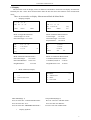
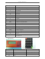

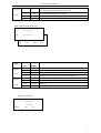

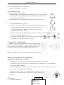

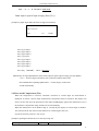

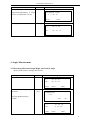
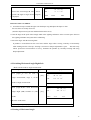
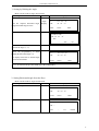
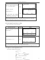
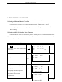
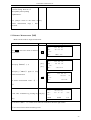

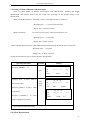
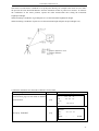
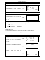
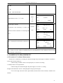

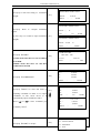
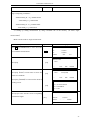
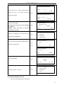
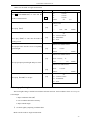
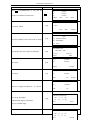
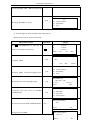
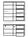
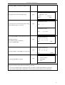

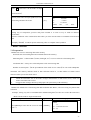

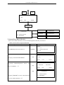
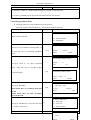

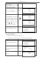

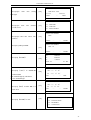


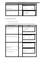

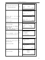
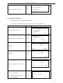
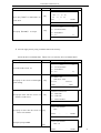
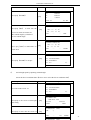


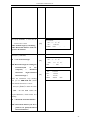


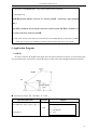

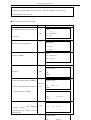
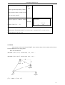
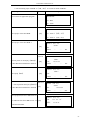
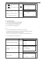
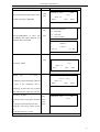
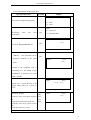

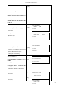

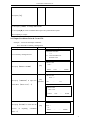

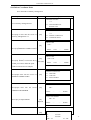

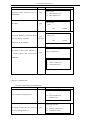
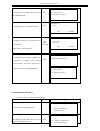
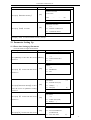
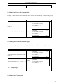

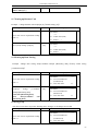
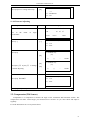

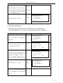

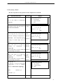
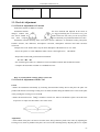
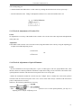
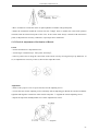

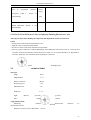


![PLAS A O ]-OR](http://vs1.manualzilla.com/store/data/005852706_1-5db0b7ed584537f0e62af161fb124638-150x150.png)