1
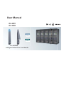
Toll Free: 1-888-865-6888
Tel: 510-226-8368 Fax: 510-226-8968
Email: [email protected]
User Manual
DL-2001
DL-2002
DL-1003P/M
Intelligent Cabinet Door Lock Handle
Legal Information
First English printing, October 2002
Information in this document has been carefully checked for accuracy; however, no guarantee is given to the correctness
of the contents. The information in this document is subject to change without notice. We are not liable for any injury or
loss that results from the use of this equipment.
Safety Instructions
Please read all of these instructions carefully before you use the device. Save this manual for
future reference.
■
■
■
■
■
■
■
■
■
■
■
Unplug equipment before cleaning. Don’t use liquid or spray detergent; use a moist cloth.
Keep equipment away from excessive humidity and heat. Preferably, keep it in an air-conditioned environment with
temperatures not exceeding 40º Celsius (104º Fahrenheit).
When installing, place the equipment on a sturdy, level surface to prevent it from accidentally falling and causing
damage to other equipment or injury to persons nearby.
When the equipment is in an open position, do not cover, block or in any way obstruct the gap between it and the
power supply. Proper air convection is necessary to keep it from overheating.
Arrange the equipment’s power cord in such a way that others won’t trip or fall over it.
If you are using a power cord that didn’t ship with the equipment, ensure that it is rated for the voltage and current
labeled on the equipment’s electrical ratings label. The voltage rating on the cord should be higher than the one listed
on the equipment’s ratings label.
Observe all precautions and warnings attached to the equipment.
If you don’t intend on using the equipment for a long time, disconnect it from the power outlet to prevent being
damaged by transient over-voltage.
Keep all liquids away from the equipment to minimize the risk of accidental spillage. Liquid spilled on to the power
supply or on other hardware may cause damage, fire or electrical shock.
Only qualified service personnel should open the chassis. Opening it yourself could damage the equipment and
invalidate its warranty.
If any part of the equipment becomes damaged or stops functioning, have it checked by qualified service personnel.
What the warranty does not cover
■
■
■
Any product, on which the serial number has been defaced, modified or removed.
Damage, deterioration or malfunction resulting from:
Accident, misuse, neglect, fire, water, lightning, or other acts of nature, unauthorized product modification, or
failure to follow instructions supplied with the product.
Repair or attempted repair by anyone not authorized by us.
Any damage of the product due to shipment.
Removal or installation of the product.
Causes external to the product, such as electric power fluctuation or failure.
Use of supplies or parts not meeting our specifications.
Normal wear and tear.
Any other causes which does not relate to a product defect.
Removal, installation, and set-up service charges.
□
□
□
□
□
□
□
□
Regulatory Notices Federal Communications Commission (FCC)
This equipment has been tested and found to comply with the limits for a Class B digital device, pursuant to Part 15 of
the FCC rules. These limits are designed to provide reasonable protection against harmful interference in a residential
installation.
Any changes or modifications made to this equipment may void the user’s authority to operate this equipment. This
equipment generates, uses, and can radiate radio frequency energy and, if not installed and used in accordance with the
instructions, may cause harmful interference to radio communications.
However, there is no guarantee that interference will not occur in a particular installation. If this equipment does cause
harmful interference to radio or television reception, which can be determined by turning the equipment off and on, the
user is encouraged to try to correct the interference by one or more of the following measures:
■ Re-position or relocate the receiving antenna.
■ Increase the separation between the equipment and receiver.
■ Connect the equipment into an outlet on a circuit different from that to which the receiver is connected.
www.RackmountMart.com
Before Installation
■
■
■
■
It is very important to locate the equipment in a suitable environment.
The surface for placing and fixing the equipment should be stable and level or mounted into a suitable
cabinet.
Make sure the place has good ventilation, is out of direct sunlight, away from sources of excessive dust, dirt, heat,
water, moisture and vibration.
Position the equipment with respect to related facilities.
Control Box Installation
■
■
Suggest the installation at the rear top mounting of cabinet
M6 screws set not provided.
www.RackmountMart.com
Content
Part I.
Hardware & Network Setup
< 1.1 > Tips for Hardware
P.1
Key Hardware
< 2.1 > Package Contents
P.2
< 2.2 > Control Box
DL-2001 / DL-2002
P.3
< 2.3 > Handle
DL-1003P / DL-1003M
P.8
< 2.4 > Door Sensor - Inductive / Mechanical
P.15
PDU & Fan Unit
< 3.1 > PDU
P.20
< 3.2 > Fan Unit
P.21
Environmental Sensor & Peripherals
< 4.1 > Temp. & Humid Sensor
P.23
< 4.2 > Smoke Sensor
P.24
< 4.3 > Shock Sensor
P.25
< 4.4 > Water Sensor
P.26
< 4.5 > LED Light Bar
P.27
< 4.6 > LED Beacon
P.28
Network Connection
< 5.1 > Daisy Chain
P.29
< 5.2 > Star
P.29
< 5.3 > Mixed
P.30
Application
< 6.1 > Data Centre
P.31
< 6.2 > Intelligent Building
P.32
< 6.3 > Remote Site
P.33
< 6.4 > Branches
P.34
www.RackmountMart.com
Part II.
Software & System Setup
< 7.1 > Tips for System Setup
P.35
< 8.1 > Key Word & Cabinet Icon
P.36
Software Installation & Activation
< 9.1 > Key features
P.39
< 9.2 > CD Key Box
P.40
< 9.3 >
Management PC & Client PC Requirement
P.41
< 9.4 >
OS Platform & Web Browser
P.42
< 9.5 >
Prerequisite before Software Installation
P.42
< 9.6 >
Software Installation
P.43
< 9.7 >
Remote Access
P.44
< 9.8 >
Software Activation
P.45
Operation Setup
< 10.1 > Cabinet Alignment
P.48
< 10.2 > MFP - Master Floor Plan
P.51
< 10.3 > CA - Control Area
P.53
< 10.4 > User Setup
P.55
< 10.5 > Group Setup
P.56
< 10.6 > Visitor
P.58
System Setup
< 11.1 > Backup & Restore
P.60
< 11.2 > Alarm Setting / Mail Server Setting / Audio Visual Alarm
P.62
< 11.3 > Temperature Unit
P.63
< 11.4 > Door Opening Overdue Setting
P.63
< 11.5 > Time Rule
P.64
Operation & Usage
< 12.1 > Individual Cabinet Devices Enable & Disable
P.65
< 12.2 > Individual Cabinet Door open by Remote
P.67
< 12.3 > Individual Cabinet PDU Configuration & Control
P.68
< 12.4 > Individual Cabinet Fan Unit Configuration & Control
P.70
< 12.5 > Console Message
P.71
< 12.6 > PDU Outlet Grouping
P.72
< 12.7 > Device & System Event Log
P.75
< 13.1 > SNMP
P.76
< 14.1 > FAQ & Troubleshooting
P.77
www.RackmountMart.com
< 1.1 > Tips for hardware
Prepare a notebook computer
To install IP setup utilities
Start
Configure IP setting
For each Control Box ONE by ONE
Control Box installation
Place the rackmount box on the
top rear side of the cabinet
Intelligent handle installation
For front & rear door
& connect cable to Control Box
Door sensor installation
Place the sensor to the door
corner & connect to the handle
PDU & Fan installation
PDU & Fan daisy chain setting
Sensor & peripheral installation
Connect sensor & peripheral
to Control Box
Control Box Cascade
Connect Control Box by daisy chain
via Cat5/6 cable
Network setup
Daisy Chain / Star / Mixed
connection
Complete
P.1
www.RackmountMart.com
Key Hardware
< 2.1 > Package Contents
Unpacking
The equipment comes with the standard parts shown on the package contents. Check and make sure they are included and in good
condition. If anything is missing, or damage, contact the supplier immediately.
DL-2002
- DL-2002 OR DL-2001 Control Box, 1 pc
- DL-1003 MiFARE OR Proximity door lock handle, pair
- Inductive OR Mechanical door sensor, pair
OR
- Front door cable, 2-section with joint connector, 1 pc ( 3150mm )
DL-2001
- Rear door cable, 2-section with joint connector, 1 pc ( 2350mm )
- 6’ Power cord, 1 pc
- Activated smartcard, 1 pc
- Key, 1 pc
- Cable clip, 8 pcs
Patented and Worldwide
Patents Pending
DL-1003P OR DL-1003M
Handle mounting screw set :
- M5 x 12mm screw, 6 pcs
Card# 12345678
Card# 12
Each package bundled with smartcard x 1. The card
on the bottom right shows card number information :
P.2
www.RackmountMart.com
< 2.2 > Control Box
DL-2001 / DL-2002
DL-2001
6
DL-2002
1
2
7
3
4
5
11
8
12
1
Power input
6
Temp. LED display x 2
2
Dual power input ( option )
7
Smoke / Shock sensor port x 2
3
Door cable DB-9 connector x 2
8
LED Light Bar port x 2
9
Port for 3rd party alarm board x 1
Connect to the front and rear handle
4
“Act in Out” LED
5
Daisy chain RJ45 port x 2
( Link & Out )
13
9
10
14
10
LED beacon port x 1
11
Temp. & Humid. sensor port x 2
12
PDU port x 1 ( RJ-45, up to PDU daisy chain level x 4 )
13
Fan unit port x 1 ( RJ-45, up to fan unit daisy chain level x 2 )
14
Water sensor port x 2
DL-2001 / DL-2002 Specification
Product Dimension ( W x D x H )
400 x 135 x 39.7 mm / 15.7 x 5.3 x 1.6 inch
Net Weight
1.06 kgs ( 2.3 lbs )
Power Consumption
Auto-sensing 100~240VAC
50 / 60Hz 0.5A, Max. 48 Watt
Operating Temperature
0° to 55°C Degree
Storage Temperature
-5° to 60 °C Degree
Relative Humidity
5~90%, non-condensing
Mounting
1U Rackmount
Safety Regulatory
FCC & CE certified
Environmental
RoHS2 & REACH compliant by SGS
P.3
www.RackmountMart.com
Key hardware Installation Diagram - Control Box / Handle / Door Sensor
3
1
5
4
3
2
5
4
2
Rear Door
Front Door
1
Control Box
2
SmartCard handle
3
Door sensor with 6’ cable
4
Door cable ( door section )
5
Door cable ( cabinet section )
Control Box Daisy Chain Connection
DL-2002
DL-2001
DL-2002
Up to 50 boxes in a single daisy chain
Up to 100 meters in a single daisy chain
P.4
www.RackmountMart.com
< 2.2 > Control Box DL-2001 / DL-2002
Installation Diagram - PDU / Fan / Sensor / Peripheral
3
Front Door
2
4
Rear Door
1
5
6
7
8
Item
Qty.
Location
1
LED Light Bar
2
front & rear top inside
2
Smoke Sensor
1
rear inside top
3
Flashing LED Beacon
1
front cabinet roof
4
Temp. & Humid. Sensor
2
any inside position
5
Shock Sensor
1
upper inside
6
Fan Unit
2
door mount or rackmount
7
PDU
4
vertical or rackmount
8
Water Sensor
1
surrounding cabinet on floor
P.5
www.RackmountMart.com
IP Setup for Control Box
Before place the Control Box to the cabinet, user MUST configure the IP setting for the Control Box. It takes
around 1-2 minutes to complete :
1. Prepare a notebook computer to download the IP setup utilities from the link below :
http://www.rackmountmart.com/downloads.html
2. Double click the InfraBoxSetup.msi and follow the instruction to complete the utilities installation.
3. Power ON the Control Box.
4. Go to each Box with the notebook computer & a piece of CAT. 5 / 6 cable to configurate the Box
as below.
CAT. 5 / 6 cable
To
Control Box LAN port
To
notebook computer
LAN port
P.6
www.RackmountMart.com
< 2.2 > Control Box DL-2001 / DL-2002
IP Setup for Control Box
Write down the new IP address for < 10.2 > MFP - Master Floor Plan
5. Click “ Scan “ to search the connected boxes.
6. Change the IP address / Subnet mask / Gateway, then Click “ Save “ to confim the setting of Control Box.
The default IP address is as below :
IP address:
192.168.0.20
Subnet mask:
255.255.255.0
Gateway:
192.168.0.254
Please take the procedure no. 3 to 6 for all boxes ONE BY ONE.
P.7
www.RackmountMart.com
< 2.3 > Handle DL-1003P / DL-1003M
Custom Mounting Cut-out on Cabinet Door for Handle Installation :
It is highly important to make a correct handle mounting cut-out on cabinet door.
Please 100% follow the diagram on the below to make the cut-out.
Unit : mm
Cabinet
>>>>>
door
P.8
www.RackmountMart.com
< 2.3 > Handle DL-1003P / DL-1003M
Dimension
Side View
Close
Side View
Open
54°
273
Unit : mm
36
DL-1003 handle design supports left side & right side open
P.9
www.RackmountMart.com
Handle Installation Steps
1. Mount DL-1003 handle to the custom handle mounting cut-out position.
2. Insert the bundled M5 x 12mm screw x 3 pcs to secure the handle in place.
M5 x 12mm
screw
While insert the screws to secure the handle with
electronic screwdriver, please set the torque
NOT exceed 8 kgf/cm
P.10
www.RackmountMart.com
< 2.3 > Handle DL-1003P / DL-1003M
Parts of Cabinet Door Locking Bar
Three parts available for cabinet manufacturer
3
to produce the cabinet door locking bar system
integrated with DL-1003 handle .
2
1 Locking bar handle bracket, pc
Order part no. : 404 - 8 - 02111
material : alloy
( fixing screw not provided )
>>>>>
Dimension Diagram
on next page
2
Locking
Bar
1
3
2 Locking bar retaining bracket, pc
Order part no. : 314 - 0 - 10010
material : alloy
( fixing screw not provided )
2
Dimension Diagram
on next page
3 Locking bar roller, pc
Order part no. : 314 - 0 - 10020
material : alloy
( fixing screw not provided )
Dimension Diagram
on next page
3
P.11
2
www.RackmountMart.com
1 Locking bar handle bracket, pc
Order part no. : 404 - 8 - 02111
material : alloy
( fixing screw not provided )
P.12
www.RackmountMart.com
< 2.3 > Handle DL-1003P / DL-1003M
2 Locking bar retaining bracket, pc
Order part no. : 314 - 0 - 10010
material : alloy
( fixing screw not provided )
3 Locking bar roller, pc
Order part no. : 314 - 0 - 10020
material : alloy
( fixing screw not provided )
P.13
www.RackmountMart.com
Important Note for Handle
Under Smartcard mode, always keep key cylinder to 12 o’clock direction.
Sensor
area
Key lock mode
Present the smartcard and
touch the handle sensor
area for 1 to 2 seconds
Key cylinder to 9 o’clock direction
Under key lock mode, even present the
smartcard, the handle still keeps locked.
Key unlock mode
Key cylinder to 3 o’clock direction
Under key unlock mode, the handle
keeps unlocked.
Smartcard mode
For smartcard operation,
keep key cylinder always
to 12 o’clock direction.
P.14
www.RackmountMart.com
Unless the smartcard handle is defective, lock / unlock the handle by key is NOT recommended
Please insert & turn the key with push force
Key lock mode
Key cylinder to 9 o’clock direction.
Key unlock mode
Key cylinder to 3 o’clock direction.
Maintenance Key
( DLS-503 )
Improper key usage may cause the cylinder stuck at abnormal direction 1 to 2 o’ clock.
Under this circumstance, the maintenance key (DLS-503) is required to solve the problem.
Please insert the maintenance key to the cylinder with push force for turning it to normal
direction 9 or 12 or 3 o’clock.
P.15
www.RackmountMart.com
< 2.3 > Handle DL-1003P / DL-1003M
Handle Operation
How to unlock the handle & open the door properly
Locked status in
blue or green
Unlocked status in
silver white
Flashing
Flashing
Stop
>>>
To open the door
( within 10 seconds )
Within 10 seconds after smartcard
detection, users should :
- lift up the handle
- open the door
- return the handle to park
position properly in case reckless
collision causes handle damage.
Over 10 seconds, the
handle still keeps unlock.
Unlock the handle but NOT open the door
Locked status in
blue or green
Unlocked status in
silver white
Unlocked status in
red
If DO NOT lift up the handle and open
the door within 10 seconds, the LED
will change to RED to draw user’s
attention that the handle in unlock
status and cabinet security at risk now.
Flashing
>>>
10 seconds
Unauthorized door-open
Locked status in
blue or green
Unlocked status in
flashing red
NO Authenticated
Smartcard Detection
Door Opening
improperly or by force
If the door is opened improperly or
by force, handle LED will turn to
red flashing with audio alarm ‘beep’
sound.
How to close the door properly
Unlocked status in
silver white
Locked status in
blue or green
Users should :
- lift up the handle
- close the door
- return the handle to park
position properly
To close the door
( within 10 seconds )
Over 10 seconds, the
handle will auto-lock.
P.16
www.RackmountMart.com
< 2.4 > Door Sensor - Inductive
Inductive Door Sensor, pair ( DLS-102 )
Features
light weight / adhesive
mini size ( 32.5 x 12.2 x 9.2 mm )
no custom cutting required on door
Front View
12.2 mm
2
1
32.5 mm
3
4
9.2 mm
Side View
1
Sensor area
2
Red LED ( light up while door opening )
3
2m cable
4
Cable jack ( connect to handle )
5
2mm adhesive tape
5
Package content
Inductive sensor w/ 2m cable x 2
2mm adhesive tape x 6
P.17
www.RackmountMart.com
< 2.4 > Door Sensor - Inductive
Suggested
sensor position
Installation steps
- connect to the handle
- guide & fix the cable with cable clips ( bundle with handle package )
- place the sensor at the top of the door, close to the opening side
- adjust the sensor with adhesive tape to ensure the sensing distance
between door to frame within 3mm while door in close status
Requirements
cabinet frame made of ferrous metal ( iron )
sensing distance 3mm
Sensor Operation
DOOR OPEN
- open door
- inductive sensor lose detection with cabinet frame
- Red LED of sensor light up
- DOOR OPEN SIGNAL sends out
DOOR CLOSE
- close door
- inductive sensor detects the cabinet frame
- DOOR CLOSE SIGNAL sends out
Door
frame
Cabinet
frame
Door
frame
CLOSED
Cabinet
frame
OPENED
Sensing distance
< 3mm
Sensing distance
> 3mm
P.18
www.RackmountMart.com
< 2.4 > Door Sensor - Mechanical
Mechanical Door Sensor ( DLS-101 )
Features
low cost / precise
cost efficient integration to new cabinet
Front View
unit : mm
Top View
1
Side View
11
7.3
22.5
3
15.0
2
3
1
Steel mounting plate with 2 screw holes
2
Cable connector
3
Press button ( total travel distance : 9.25 mm
15.75
6.5
52.0
9.25
)
( min. actuation distance : 3.00 mm )
Package content
Mechanical sensor w/ 2m cable x 2
Mounting screws 6#32x4.5mm x 2
unit : mm
Requirements
37.5
custom hole cutting required on doors
23
ordering a sample for custom cutting is highly suggested
2-
12.5
6.3
min. actuation distance : 3.00 mm
total travel distance : 9.25 mm
3.5
Dimension of door cutting hole
- circle hole x 2 for screw mounting
- rectangle hole x 1 for sensor installation
P.19
www.RackmountMart.com
< 2.4 > Door Sensor - Mechanical
Installation steps
Suggested
sensor position
- connect to the handle
- place the sensor at the top middle of the door
- install the sensor in the custom hole
- secure it with bundled mounting screws 6#32x4.5mm x 2
Sensor Operation
DOOR CLOSE
- close door
- Sensor button is pressed on
DOOR OPEN
- open door
- Sensor button is released
- DOOR CLOSE SIGNAL sends out
- DOOR OPEN SIGNAL sends out
Door
frame
Door
frame
Cabinet
frame
Cabinet
frame
OPENED
CLOSED
Button released
Actuation distance > 3mm
Physical touch required
P.20
www.RackmountMart.com
< 2.4 > Door Sensor
Specification
Inductive Door Sensor
Part no.
Sensitivity
DLS-102
3.00 mm
Operating Force
Sensing distance
Max. 3mm
/
/
Sensing object
Voltage
9.25 mm
3.5±1 N
Ferrous metal
/
/
12VDC, powered by sensor port
Current Consumption
Housing
DLS-101
/
/
/
Actuation
Travelling Distance
Power Requirement
Mechanical Door Sensor
100mA
Material
Plastic
Color
Black
Connection
Cable Length
sensor w/ 2m cable
Environmental
Operating
-20 to 60°C Degree
Storage
-20 to 60°C Degree
Relative Humidity
5~90%, non-condensing
Dimensions
Product
-30 to 70°C Degree
32.5L x 12.2W x 9.2H mm
52W x 22.5L mm
( with metal plate )
6g
14g ( with metal plate )
Weight
Net
Supply includes
1
Inductive door sensor
with 2m cable
Mechanical door sensor
2
2mm Adhesive tape
Metal plate
3
/
2m cable
Compatibility
DL-2001 / 2002 series
FCC & CE certified
Safety Regulatory
Environmental
RoHS2 & REACH compliant by SGS
P.21
www.RackmountMart.com
< 3.1 > PDU
Under a DL Series network, each Control Box supports our intelligent PDU x 4 in a daisy chain.
Each PDU comes with Temp. & Humid. sensor port x 2
W series : monitored PDU
WS series : switched PDU
WSi series : outlet level measurement switched PDU
Please visit below link to select desired PDU & download the PDU drawing & specifications.
http://www.rackmountmart.com/html/pdu.htm
Control Box
Cat 5 / 6 cable Up to 20M
Cat 5 / 6 cable
Up to 20M
Cat 5 / 6 cable
Up to 20M
Cat 5 / 6 cable
Up to 20M
4
1st level
PDU meter
2nd level
PDU meter
3rd level
PDU meter
4th ( last ) level
PDU meter
Max. daisy chain distance from Control Box to the 4th PDU up to 80M
PDU level setting :
Step 1 - Press the
&
button to
display no.9
Step 2 - Press the
&
button to
PDU ID
Step 3 - In display 9.1, Press the
and press
Step 4 - Press
&
and press
and press
to confirm
to confirm
button to select PDU level no.1 - 4
to confirm
to exit
( Neglect Group no. in display 9.1. It’s not appliable to DL Series Software )
For details about PDU level setting, please refer to IPM-03 user manual < 3.1 > :
http://www.rackmountmart.com/dataSheet/IPM-03.pdf
P.22
www.RackmountMart.com
< 3.2 > Fan Unit
Under a DL Series network, each Control Box supports
Each fan unit comes with TEMP. sensor port x 1
our remote fan unit x 2 in a daisy chain.
DL-2002
2nd ( last ) level Fan unit
OUT
Cat 5 / 6 cable
Up to 20M
LINK
OUT
LINK
1st level Fan unit
Max. daisy chain distance from Control Box to the 2nd fan unit up to 40M
Please visit below link to select desired Fan unit models
http://www.rackmountmart.com/html/ra4015-r.htm
http://www.rackmountmart.com/html/ra4017-r.htm
Using
dip switch no. 1, 2, 3, 4, 5, 6 & 8
Cascaded
FAN unit
to setup each FAN unit level as below :
Dip switch no.
1
2
3
4
5
6
8
1st level Fan Unit
On
On
On
On
On
On
Off
2nd level Fan Unit
Off
On
On
On
On
On
Off
Using
dip switch no. 7
ON
OFF
to setup each FAN unit audio alarm as below :
Dip switch 7
Enable
On
Disable
Off
P.23
If enable the audio alarm, the buzzer will
sound when the outside temperature is
over the preset alarm temperature.
www.RackmountMart.com
< 3.2 > Fan Unit
Specification
Remote Fan
Model
RA4015-R
RA4017-R
No. of Fan
3 / 6 / 9
6 / 9
Mounting
1U
Door mount
CFM Level
Normal / High / Max.
Individual Fan ON / OFF
Yes
Individual Fan CFM
108 CFM
Unit CFM ( Approximately )
Temperature
Sensor
324 / 648 / 972 CFM
IP Remote Access
Not available, must be via Master IP fan on the 1st level
Daisy Chain Level
2nd to 16th level
Temperature Port
1 x temperature sensor port ( sensor bundled )
Measurement Range
0 to 99.9°C
Measurement Accuracy
+/- 1.5%
Temperature Alarm
Power
Input
Yes
100V or 240V AC at 50 or 60Hz via IEC type cord
Consumption
Environmental
Conditions
20W / 40W / 60W
0 to 50°C
Storage
-5 to 60°C
90%, non-condensing
Shock
Weight
50G peak acceleration ( 11ms, half-sine wave )
Vibration
58~100Hz / 0.98G ( 11ms / cycle )
Model
Product Dimension
RA4015-3-R
480 x 298.3 x 43.5 mm
18.9 x 11.7 x 1.71 inch
RA4015-6-R
480 x 458.3 x 43.5 mm
18.9 x 18 x 1.71 inch
RA4015-9-R
480 x 623.3 x 43.5 mm
18.9 x 24.5 x 1.71 inch
RA4017-6-R
195 x 42.9 x 1466 mm
7.7 x 1.7 x 57.7 inch
RA4017-9-R
195 x 42.9 x 1466 mm
7.7 x 1.7 x 57.7 inch
Model
Net Weight
RA4015-3-R
4 kgs / 8.8 lbs
RA4015-6-R
6.8 kgs / 15 lbs
RA4015-9-R
9 kgs / 19.8 lbs
RA4017-6-R
4.3 kgs / 9.5 lbs
RA4017-9-R
5 kgs / 11 lbs
FCC & CE certified
Safety Regulatory
Environmental
40W / 60W
Operating
Relative Humidity
Dimensions
648 / 972 CFM
RoHS2 & REACH compliant by SGS
P.24
www.RackmountMart.com
< 4.1 >
Temp. & Humidity Sensor
Each Control Box provides Temp. & Humid. Sensor port x 2. If more TH sensors required, two temp. & humid. sensor ports
on each integrated PDU can be applied.
Part no.
Temperature
Sensitivity
Temp. & Humid. Sensor
Temp. Sensor
EMS-102-2
EMS-101-2
Range
Accuracy
0 to 80°C ( 32 to 176°F )
Resolution
0.1°C ( 0.2°F )
Response Time
Relative
Humidity
Sensitivity
Range
Accuracy
Resolution
Response Time
Power
Requirement
5 to 30 sec
0 to 100% R.H
/
0 to 100, ±8.0% R.H
20 to 80, ±4.5% R.H.
/
1% R.H.
/
8 sec
/
Voltage
12VDC, powered by sensor port
20mA
Current Consumption
Power consumption
0.24 Watt
Power on indicator
Housing
Red
Green
Chassis & Cover
Plastic
Color
Dark gray
Installation
Connection
Cable Length
Magnetic base for unrestricted installation
TH sensor w/ 2m cable ( standard )
TH sensor w/ 4m cable ( option )
Cable Specification
Cable Color
±1°C ( ±2°F)
±0.5°C typical ( ±1°F )
T sensor w/ 2m cable ( standard )
T sensor w/ 4m cable ( option )
4-wired 3.5mm to RJ11
Black
Beige
Operating
0 to 80°C Degree
Storage
-5 to 80°C Degree
Humidity
0~100%, non-condensing
Dimensions
Product
30L x 25W x 18H mm
Weight
Net
Supply includes
1
TH Sensor
2
4-wired 3.5mm to RJ11 cable ( 2m, black color )
Environmental
66g
Temperature Sensor
W / WS / Wi / WSi series PDU
Compatibility
DL-2002 series
EM-1001 & EM-1002
Safety Regulatory
Environmental
FCC & CE certified
RoHS2 & REACH compliant by SGS
P.25
www.RackmountMart.com
< 4.2 >
Smoke Sensor
Smoke sensor comes with a RED LED. When smoke alarm triggers, the RED LED lights on with beep sound continuously.
Smoke Sensor
Part no.
EMS-201-1
Sensitivity
Smoke sensitivity
0.15 ~ 0.3 dB/m
Alarm Output
Solid State Relay
24VDC@1A
Alarm LED
Red
Audio Alarm
80 dB
Continuous beeps
Audio Alarm Pattern
Power Requirement
Voltage
12VDC, powered by sensor port
200uA
Current Consumption
Power ON LED
Housing
Red LED flashes every 6 seconds
Chassis & Cover
ABS plastic
Color
Ivory White
Connection
Cable Length
1m / 3m ( option )
Environmental
Operating
-5 to 50°C Degree
Storage
-10 to 60°C Degree
Humidity
5~90%, non-condensing
Dimensions
Product
103L x 103W x 55H mm
Weight
Net
Supply includes
1
165g
Smoke Sensor with 1m cable
DL-2002 series
Compatibility:
EM-1001 & EM-1002
FCC & CE certified
Safety Regulatory
Environmental
RoHS2 & REACH compliant by SGS
P.26
www.RackmountMart.com
< 4.3 >
Shock Sensor
Shock sensor comes with a RED LED. When shock alarm triggers, the RED LED lights on continuously.
Shock Sensor
Part no.
Sensitivity
EMS-301-1
Detection radius
3.5 m
Adjustable sensitivity
Alarm Output
Internal micro knob with screwdriver cross slot
Solid State Relay
12VDC@100mA
Alarm hold time
Approx. 2.0 sec.
Alarm LED
Power Requirement
Red
Voltage
12VDC, powered by sensor port
Current Consumption
15mA
Power consumption
Housing
0.18 Watt
Chassis & Cover
ABS plastic
Color
White
Connection
Cable Length
1m / 3m ( option )
Environmental
Operating
-5 to 55°C Degree
Storage
-10 to 60°C Degree
Humidity
5~90%, non-condensing
Dimensions
Product
26 x 85 x 24 mm
Weight
Net
Supply includes
1
40g
Shock Sensor with 1m cable
DL-2002 series
Compatibility
EM-1001 & EM-1002
FCC & CE certified
Safety Regulatory
Environmental
RoHS2 & REACH compliant by SGS
P.27
www.RackmountMart.com
< 4.4 > Water Sensor
+
Water Sensor
Part no.
Power Requirement
EMS-401-3
Measurement Range
Wet or Dry (-20°C to 60°C)
Rope Sensor Length
5m
Voltage
5VDC, powered by sensor port
Power consumption
125 mWatt
Connection
Extension cable length
3m ( non-detection )
Environmental
Operating
-20 to 60°C Degree
Storage
-20 to 80°C Degree
Weight
Net
450g ( Sensor & extension cable )
Supply includes
1
Rope water sensor
2
Extension cable
DL-2002 series
Compatibility
EM-1001 & EM-1002
FCC & CE certified
Safety Regulatory
Environmental
RoHS2 & REACH compliant by SGS
P.28
www.RackmountMart.com
< 4.5 > LED Light Bar
Under DL Series software, the LED light bar can be enabled / disabled / always ON.
When the LED light bar is enabled & connected, it will be ON within 10 seconds after the handle lock is released.
LED Light Bar
Part no.
Light
Power Requirement
Housing
EMS-601-2
Color
Cool White
Output
250 Lumens
Color Temperature
5600-7000K
Number of LED
18 High Output CREE SMD LED
Life Expectancy
30,000 hrs
Voltage
12VDC, powered by sensor port
Current Consumption
0.375A
Power consumption
4.5 Watt
Chassis
Extruded aluminum with silver powder coat
Diffuser
Acrylic with milky white
Magnetic base for unrestricted installation
Installation
Connection
Cable Length
2m / 3m ( option )
Environmental
Operating
-20 to 50°C Degree
Storage
-20 to 60°C Degree
Relative Humidity
Dimensions
Product
Weight
Net
5~90%, non-condensing
300L x 20W x 12H mm
84g
DL-2002 series
Compatibility
EM-1001 & EM-1002
FCC & CE certified
Safety Regulatory
Environmental
RoHS2 & REACH compliant by SGS
P.29
www.RackmountMart.com
< 4.6 > LED Beacon
The LED Beacon can be stuck firmly by the bundled adhesive tape.
LED Beacon
Part no.
Notification
EMS-602-1
Len Color
Blue
Light Source
White
Flash Rate
Power Requirement
120 flashes per minute
Voltage
12VDC, powered by sensor port
0.175A
Current Consumption
Housing
Cover Len
Polycarbonate
Color
Blue
Connection
Cable Length
Environmental
Operating
-20 to 50°C Degree
Storage
-20 to 60°C Degree
1m / 3m
Relative Humidity
Dimensions
Product
Weight
Net
Supply includes
1
5~90%, non-condensing
72L x 72W x 45H mm
50g
LED Beacon with 1m cable
DL-2002 series
Compatibility
EM-1001 & EM-1002
FCC & CE certified
Safety Regulatory
Environmental
RoHS2 & REACH compliant by SGS
P.30
www.RackmountMart.com
Network Connection
DL Network solution provides 3 connection ways - Daisy Chain, Star , Mixed.
Which connection applied is subject to the site scale, environment and users’ requirements.
< 5.1 > Daisy Chain
Connect all boxes by Cat5/6 cable, and no any network switch required
Client PCs
Key Benefits
Simple connection
No network switch required
Appropriate for small networks
Management
PC
Quantity of Box / Cabinet : Up to 50
Total distance in a single daisy chain : Up to 100M
< 5.2 > Star
Connect to network switch by a point-to-point connection
Key Benefits
Appropriate for large networks
Client PCs
Increased fault tolerance
Easy for troubleshooting
Network
Switch
Management
PC
Network switch required
Total distance for each Box to Network Switch : Up to 100M
P.31
www.RackmountMart.com
Network Connection
< 5.3 > Mixed
Combining daisy chain with star connection
Key Benefits
Most effective and practical for large scale of networks
Take all advantages of Daisy Chain and Star connection
Flexible to meet a variety of network environments and needs
Up to 50 in each row
Client PCs
Network
Switch
Management
PC
Up to 50 in each row
otal Box Qty in Mixed Network : Up to 3000
P.32
www.RackmountMart.com
Application
< 6.1 > Data Center
By mixed connection, DL Network solution can be scalable up to 3000 cabinets. DL-2001 and DL-2002 can be
coexisted in the same network. Users are enabled to manage and remotely access all cabinets under a centralized
and user friendly GUI.
Connect the 1st Box in each daisy chain to the network switch
Connect the management PC and client PCs via the network switch
Up to 3000 boxes / Cabinets
Client PCs
Network Switch
Management PC
P.33
www.RackmountMart.com
< 6.2 > Intelligent Building
It is essential for a Multi-Storey Intelligent Building to be applied with a centralized management system for the building’s
mechanical and electrical equipment such as security, power, ventilation, and lighting systems, etc.
DL Network system allows equipment to be distributed throughout a building simply by deploying an Ethernet network.
To keep capital costs down, DL Network can also be cascaded between boxes up to 100m over a Cat5/6 cable. Signal
weakness problem for long distance between boxes can be solved by applying network hubs with repeater function.
Connect the DL Network in each floor via the network ethernet / fiber switch
Up to 3000 boxes / Cabinets
Daisy Chain Scenario
(Up to 50)
Daisy Chain Scenario
(Up to 50)
Backbone Network /
Fiber Switch
Star Connection
Network Switch for Star / Mixed
Connection
(Up to 50)
Star Connection
(Up to 50)
Mixed Connection
(Up to 50)
Mixed Connection
(Up to 50)
Management
PC
Control Room
Client PCs
P.34
www.RackmountMart.com
< 6.3 > Remote Site
DL Network solution can be also applied to the remote site for access and monitoring over IP anytime and anywhere.
DL Network Software License is required for each remote site / management PC
Headquarter
Workstation
Router
Remote Site A
DL network
Internet
VPN
Router
Management
PC
VPN
Router
Network
Switch
Client PCs
Remote Site B
DL network
Management
PC
P.35
www.RackmountMart.com
< 6.4 > Branches
For a global or scalable company, it is vital to remote access and monitor the network of their nationwide and worldwide
branches. DL Network provides an ideal solution to keep an eye on cabinet access security and environmental condition.
DL Network Software License is required for each remote site / management PC
Up to 50 in each row
Branch A
DL network
Headquarter
Workstation
VPN
Router
Management
PC
Router
Internet
VPN
Router
Up to 50 in each row
Switch
Management
PC
Switch
Up to 50 in each row
Branch B
DL network
VPN
Router
Management
PC
Branch C
DL network
P.36
www.RackmountMart.com
< 7.1 > Tips for System Setup
Prepare a management PC
Start
- Install Java SE 6 / 7
- Install Mircosoft Visual C++ 2008
SP1 Redistributable Package
Software installation
- Disable firewall
- Install DL Network manager
- Reboot management PC
Remote Access Setting
- Enable firewall
- Set incoming port
- Set outgoing port
Software activation
- Activate DL Network manager
MFP - Master Floor Plan
- Create MFP
- Add cabinet
- Configure cabinet IP setting
CA - Control Area
- Create CA
- Load cabinet
User Setup
- Create user
Group Setup
- Create user group
System Setup
- Alarm / email server / temp. unit
- Door opening overdue setting
- Time rule
- Backup & restore
Complete
P.37
www.RackmountMart.com
< 8.1 > Key Word
MFP - Master Floor Plan
-
An actual cabinet floor plan.
Only in MFP, you can create cabinet & configure the IP setting for the cabinet.
If you want to monitor & control cabinets & their devices, you need to build the control area.
MFP can be more than one. No. of MFP is subject to the site scale & plan by floor, zone, building, branches
or remote sites.
CA Loading
- There is a button in MFP - CA Loading. It is to provide a quick and efficient path for the user to move cabinet
to build the control area.
CA - Control Area
-
You can build a Control Area for some specific cabinets which you want to monitor, configure & control.
All cabinets in the CA should be loaded from the MFP by CA Loading button.
CA can be more than one. How many CA is subject to your plan.
CA has 2 modes : Edit mode & View mode.
Under Edit mode, you can configure not only cabinets but also devices such as PDU, fan unit & sensors.
View mode is designed for users with limited authority so they can ONLY monitor the status of cabinet & device.
User Setup
-
To build a user list. Afterward, you can use the list to build the user group.
Each user has his own login name & password for remote system login.
Each user also has his own smartcard for cabinet access.
However, before users join a user group in next step, they can do nothing.
User Group
-
You can form a user group from the user list.
You can define the user group with authority and which control area / areas to monitor & access.
Each user subordinated to ONLY ONE user group.
If the user wants to join another user group, a new login name, password & smartcard MUST BE assigned.
Each user group must select ONE time rule. All group users can access the cabinet and remote system login
according to the time period of the selected time rule.
- Without time rule assignment, all group users can do nothing.
Time Rule
-
Time rule is designed for security. It tries to restrict the users with a time period to access the system and cabinet.
In system setup section < 11.5 >, you can set time rules up to 32.
Afterward, all time rules will be shown in user group for their selection.
Only one time rule can be assigned to one user group.
P.38
www.RackmountMart.com
< 8.1 > Cabinet Icon
Cabinet Icon layer
Cabinet icon has two layers, the layer one by default shows on all control area under view mode
for status monitoring. User can click cabinet icon to switch to layer two.
Layer one
Cabinet
0014
P1 P2 P3 P4
F1
F2
-
show PDU status ( P1, P2, P3, P4 )
if PDU is enabled & connected, P icon in WHITE color
if PDU is enabled BUT disconnected, P icon in RED color
if PDU is on alarm status, P icon also in RED color
if PDU is disabled, P icon in GREY color
-
show Fan unit status ( F1, F2 )
if Fan unit is enabled & connected, F icon in WHITE color
if Fan unit is enabled BUT disconnected, F icon in RED color
if Fan unit is on alarm status, F icon also in RED color
if Fan unit is disabled, F icon in GREY color
-
show TH sensor status ( S1, S2 )
if TH sensor is enabled & connected, S1, S2 icon in WHITE color
if TH sensor is enabled BUT disconnected, S1, S2 icon in RED color
if TH sensor is on alarm status, S1, S2 icon also in RED color
if TH sensor is disabled, S1, S2 icon in GREY color
-
show smoke & shock sensor status ( S3, S4 )
if smoke & shock sensor is enabled & connected, S3, S4 icon in WHITE color
if smoke & shock sensor is on alarm status, S3, S4 icon also in RED color
if smoke & shock sensor is disabled, S3, S4 icon in GREY color
-
show water sensor status ( S5, S6 )
if water sensor is enabled & connected, S5, S6 icon in WHITE color
if water sensor is on alarm status, S5, S6 icon also in RED color
if water sensor is disabled, S5, S6 icon in GREY color
Layer two
Cabinet
0014
S1 S2 S3 S4
S5
S6
P.39
www.RackmountMart.com
< 8.1 > Cabinet Icon
Door direction
Door status
Front door
Door close status in white
Cabinet
0014
Cabinet
0014
Door open status in green
P1 P2 P3 P4
F1
F2
P1 P2 P3 P4
F1
F2
F1
F2
P1 P2 P3 P4
10m
Cabinet
0014
Door open overdue status in red
( show overdue time )
Door alarm status in red
Cabinet
0014
P1 P2 P3 P4
F1
F2
Front door
Connection status
( unauthorized open )
Non-configure cabinet
In grey color
Cabinet
0014
Cabinet
0014
Normal connection status
( color in blue )
P1 P2 P3 P4
F1
F2
Cabinet
0014
P1 P2 P3 P4
F1
F2
In MFP master floor plan,
the grey cabinet icon
shows that the cabinet has
not been configured with IP
setting yet.
In CA control area, the grey
cabinet icon shows that the
cabinet has been deleted in
master floor plan.
The user should remove this
non-function cabinet from
control area.
Disconnection status
( color in red )
P1 P2 P3 P4
F1
F2
P.40
www.RackmountMart.com
Software Installation & Activation
< 9.1 > Key Features
DL Network Manager X-ISM is a LICENSED cabinet management software to monitor up to 3000
cabinets remotely.
Each Control Box connects a pair of intelligent handles to secure the cabinet access control.
Each Control Box can also connect a variety of sensors to provide an environmental monitoring solution.
To enhance the functionality, up to 12000 x kWh PDU / 6000 x Fan Unit can be monitored through
DL Network Manager as well.
Up to 100 concurrent users can access the management software remotely to achieve the demand of
multi-user / multi-tasking in nowadays’ time sharing data center operation.
DL Network Manager X-ISM
Features
Capacity
3000
100
Control Box
Concurrent user
System Setup
Backup / Restore Setting
Time Rule Setting
Alarm Mail Server Setting
Audio and Visual Alarm Output Setting
Cabinet Overview
Door
Status of Door, PDU, Sensor & Fan unit
Door open by remote
Last door open & close record
Status Monitoring
Sensor
Peripherals
Temp-Humid Alarm Threshold Setting
PDU
Energy Consumption kWh / Amp. Monitoring
Outlet Level Measurement
PDU Outlet Grouping / Schedule
Outlet Switch ON / OFF
Amp. Alarm Threshold Setting
Amp. Rising / Low Alert Threshold Setting
Temp-Humid Monitoring
Fan Unit
CFM & Temp. Monitoring
Unit CFM ( fan speed ) Setting
Auto CFM Control Setting
Individual Fan Kit ON / OFF
Fan Unit ON / OFF
Chart / Event / Reporting
System & Device Event Reporting
Temp-Humid Line Chart of Control Box
P.41
www.RackmountMart.com
< 9.2 > CD Key Box
A licensed software, DL Network Manager X – ISM, is bundled with a CD Key.
The CD Key Box consists of a software CD and a software license certificate
P.42
www.RackmountMart.com
< 9.3 > Management PC & Client PC Requirement
Management PC requirement
Management PC requirement is highly related to the no. of cabinet. Please refer to the table below :
No. of Cabinet
Processor
Memory
Hard Disk
LCD Resolution
No. of days log file
kept in database
2 - 200
Quad Core Xeon x 1
4GB
1TB x 2
1660 x 1200, 1600 x 900,
1920 x 1080
31
201 - 500
Quad Core Xeon x 1
8GB
1TB x 2
1660 x 1200, 1600 x 900,
1920 x 1080
31
501 - 1000
Quad Core Xeon x 1
16GB
2TB x 4
1660 x 1200, 1600 x 900,
1920 x 1080
15
Over 1000
Quad Core Xeon x 2
32GB
4TB x 4
1660 x 1200, 1600 x 900,
1920 x 1080
7
- The default service port of web server is 80.
- A dedicated PC to run X- ISM is recommended.
- If the PC is a notebook computer, the power adapter MUST be plugged in & power ON.
- Make sure the management PC is POWER ON & X-ISM is under operation.
Otherwise, daily data backup will NOT be proceeded.
To legally access Microsoft server software, a Client Access License ( CAL ) may be required.
For more information, please visit the link below :
http://www.microsoft.com/licensing/about-licensing/client-access-license.aspx
Client PC requirement
Processor
Memory
Hard Disk
LCD Resolution
Dual Core x 1
2GB
500GB
1660 x 1200, 1600 x 900,
1920 x 1080
For better view of cabinet status, an appropriate LCD size is necessary.
Please refer to the table below :
No. of Cabinet in CA
Preferred LCD Size
2 - 100
21" ( 1920 x 1080 )
101 to 300
46” ( 1920 x 1080 )
P.43
www.RackmountMart.com
< 9.4 > OS Platform & Web Browser
OS platform
- MS Windows Server 2008 Standard Edition ( 32 bit & 64 bit, English Edition )
- MS Windows Server 2008 R2 ( English Edition )
Web browser
- I.E. Version 9.0 , 10.0
- Google Chrome Version 23 or above
Make sure users login the management PC as a member of “ Administrator “ Group before X-ISM installation & execution.
< 9.5 > Prerequisite before software installation
Components
Windows 2008 server
OS Platform standard, 32bit
Windows 2008 server
standard, 64bit
Windows 2008 server
R2
Java SE 6 / 7 ( i586 )
Java SE 6 / 7 ( x64 )
Microsoft Visual C++ 2008 SP1
Redistributable Package ( X86 )
Microsoft Visual C++ 2008 SP1
Redistributable Package ( X64 )
The firewall setting of the management PC MUST be OFF
P.44
www.RackmountMart.com
< 9.6 > Software Installation
After the Control Box installation, please follow the steps below to install the
X-ISM.exe
1. Double click the X-ISM.exe
in software CD come with the CD Key Box and follow the instruction
to complete the installation.
click “ Next ”
click “ Install ”
click “ Finish ”
Complete
The management PC must reboot before proceed to Software Activation
P.45
www.RackmountMart.com
< 9.7 > Remote Access
After software installation, administrator can turn on firewall of the management PC and set the inbound &
outbound rules of firewall.
Inbound rules :
1. Open “ Control Panel “
2. Select “ Windows Firewall “
3. Select “ Advanced settings “
4. Right Click “ Inbound Rules “ & select “ New Rules… “
5. Select “ Port “ & Click “ Next> “
6. Select “ TCP “ then input “ 80, 4000, 5432, 18081 “ in “ Specific local ports: “
7. Select “ Allow the connection “ & Click “ Next> “
8. Tick all three options & Click “ Next> “
9. Input the “ Name “ & “ Description “ of the port & Click “ Finish “
Outbound rules :
1. Open “ Control Panel “
2. Select “ Windows Firewall “
3. Select “ Advanced settings “
4. Right Click “ Outbound Rules “ & select “ New Rules… “
5. Select “ Port “ & Click “ Next> “
6. Select “ TCP “ then input “ 4001, 4003, 4006, outgoing SMTP port “ in “ Specific remote ports: “
7. Select “ Allow the connection “ & Click “ Next> “
8. Tick all three options & Click “ Next> “
9. Input the “ Name “ & “ Description “ of the port & Click “ Finish “
The port no. of outgoing SMTP port depends on the mail server setting in < 11.2 >
P.46
www.RackmountMart.com
< 9.8 > Software Activation
After software installation is completed, please follow the steps below to do the software activation
1. Click “ Start “ & Select “ Software Activation or Upgrade “
2. The “ Software Activation / Upgrade “ web page pops up
3. Input “ CD Key “ & Click “ Submit “. The “ Installation Key “ will be generated automatically.
4. Click “ Activate Online “ & go to “ Software Online Activation Centre “ directly
P.47
www.RackmountMart.com
< 9.8 > Software Activation
5. Fill in all necessary information & Click “ Submit “. Then Click “ OK “ from the pop up window to get the
“ Activation Code “
[email protected]
6. Input the “ Activation Code “ & Click “ Submit “ in the “ Software Activation / Upgrade “ web page
to complete the software activation
7. Once the software activation is completed, the following web page will be displayed.
Complete
P.48
www.RackmountMart.com
Operation Setup
After the software is activated, user can follow below steps to access the management PC and X-ISM
Manager – Matrix Server
1. Open the web browser of remote client PC
2. Enter “ http:// ManagementPC IP address/RMS_2013/RMS_2013.html “
3. Enter the login name & password
Default login name : admin
Default login password : admin
P.49
www.RackmountMart.com
< 10.1 > Cabinet Alignment
In MFP & CA, the system provides alignment function for user to arrange the cabinet in a neat way
Alignment - Left
1. Press < Shift > to select the 3 highlighted cabinets
2. Release < Shift >
3. Press < Align Left >
Alignment - Center
1. Press < Shift > to select the 2 highlighted cabinets
2. Release < Shift >
3. Press < Align Center >
P.50
www.RackmountMart.com
Alignment - Right
1. Press < Shift > to select the 2 highlighted cabinets
2. Release < Shift >
3. Press < Align Right >
Alignment - Top
1. Press < Shift > to select the 5 highlighted cabinets
2. Release < Shift >
3. Press < Align Top >
51
www.RackmountMart.com
< 10.1 > Cabinet Alignment
Alignment - Middle
1. Press < Shift > to select the 5 highlighted cabinets
2. Release < Shift >
3. Press < Align Middle >
Alignment - Bottom
1. Press < Shift > to select the 5 highlighted cabinets
2. Release < Shift >
3. Press < Align Bottom >
52
www.RackmountMart.com
< 10.2 > MFP - Master Floor Plan
-
An actual cabinet floor plan.
Only in MFP, you can create cabinet & configure the IP setting for the cabinet.
If you want to monitor & control cabinets & their devices, you need to build the control area.
MFP can be more than one. No. of MFP is subject to the site scale & plan by floor, zone, building, branches
or remote sites.
Ensure ONLY one user configures the cabinet IP in the same MFP at the same time
Add MFP
1. Click “ MFP “ tab
2. Click “ Add “
3. Input the MFP title & Description
( min. 1 char / max. 32 char )
4. Click “ OK “ to finish
Edit MFP
1. Select the MFP you want to edit
2. Click “ Edit “
3. Edit the MFP title / Description
4. Click “ OK “ to finish
53
www.RackmountMart.com
< 10.2 > MFP - Master Floor Plan
Add Cabinet
1. Select the MFP you want to add cabinet (s )
2. Click “
“ to add cabinet. ( 1 / 5 / 10 cabinets at one time )
3. Click “
“ & Click “ Yes “ to confirm cabinet addition
Cabinet IP configuration
1. Select a cabinet
2. Input : “ Cabinet No. “ (min 4 char / max. 16 char. ),
“ Title 1 “ ( min. 2 char / max. 8 char ),
“ Title 2 “( min. 2 char / max. 8 char ),
“ IP address “, Enable / Disable the email & audio alarm
( If email alarm is “ Disable “ , NO alarm email will be sent to user. )
3. Click “ Save “ to finish the cabinet IP configuration
Repeat step 1 to 3 for all cabinets ONE BY ONE.
Once the cabinet is configured, the IP address CANNOT BE edited.
Users need to delete cabinet in the MFP & create a new one.
Delete Cabinet
1. Select the cabinet you want to delete in the MFP
2. Click “
“ & Click “ Yes “ to confirm the cabinet deletion
Delete MFP
1. Select the MFP you want to delete
2. Select all cabinets in the MFP to clear first
3. Click “
“ & Click “ Yes “ to confirm to clear all cabinet
4. Then select the MFP & Click “ Delete “
5. Click “ Yes “ in the confirmation window to confirm MFP deletion
54
www.RackmountMart.com
< 10.3 > CA - Control Area
-
You can build a Control Area for some specific cabinets which you want to monitor, configure & control.
All cabinets in the CA should be loaded from the MFP by CA Loading button.
CA can be more than one. How many CA is subject to your plan.
CA has 2 modes : Edit mode & View mode.
Under Edit mode, you can configure not only cabinets but also devices such as PDU, fan unit & sensors.
View mode is designed for users with limited authority so they can ONLY monitor the status of cabinet & device.
Add CA
1. Click “ Control Area “ tab
2. Click “
“ & input the login password
in validation window to enter “ Edit Mode “
3. Click “ Add “
4. Input the CA title & Description
( min. 1 char / max. 32 char )
5. Click “ OK “ to finish CA addition
Load Cabinet
1. Go back to “ MFP “ tab
5
2. Select the MFP where the cabinet( s ) you want to load to CA
3. Click “ CA loading “
4. You can load whole MFP cabinets or part of them by tick
5. In “ Cabinet Orientation “, you can select Normal if the rear
door at bottom side, or select Inverted if the rear door at top side
6
6. Click “ Load “ button to finish CA loading.
55
www.RackmountMart.com
< 10.3 > CA - Control Area
Edit CA
1. In < CA – Edit Mode >, select the CA you want to edit
2. Click “ Edit “
3. Edit the CA title / Description
4. Click “ OK “ to finish
Delete CA
1. In < CA – Edit Mode >, select the CA you want to delete & Click “ Delete “
2. Click “ Yes “ in the confirmation window
3. Input login password in validation window to confirm CA deletion
Remove Cabinet from CA
Cabinet removal from CA
1. In < CA – Edit Mode >, select the CA you want the cabinet(s) to be removed
2. Select the cabinet(s)
3. Click “
“
4. Click “ Yes “ in the confirmation window to confirm the cabinet removal
56
www.RackmountMart.com
< 10.4 > User Setup
-
To build a user list. Afterward, you can use the list to build the user group.
Each user has his own login name & password for remote system login.
Each user also has his own smartcard for cabinet access.
However, before users join a user group in next step, they can do nothing.
Add User
1. Click “ User Setup “ tab
2. Click “ Add “
3. In the user window, please input all the fields.
5. If you want to suspend the user authority and
access temporarily, tick “ User Suspended “
( Default : untick )
6. Then click “ Save “ to finish
4. If you want to receive device alarm email, tick
“ Email Alert “ ( Default : untick )
4
5
Edit User
1. Select the user you want to edit
2. Click “ Edit “ in “ User Details ” window
3. Edit the field ( s ) you want
4. Click “ Save “ & Click “ Yes “ in the confirmation window to confirm user edition.
Delete User
1. Select the user you want to delete
2. Click “ Delete “ in “ User Details ” window & Click “ Yes “ in the warning window to confirm user deletion
57
www.RackmountMart.com
< 10.5 > Group Setup
-
You can form a user group from the user list.
You can define the user group with authority and which control area / areas to monitor & access.
Each user subordinated to ONLY ONE user group.
If the user wants to join another user group, a new login name, password & smartcard MUST BE assigned.
Each user group must select ONE time rule. All group users can access the cabinet and remote system login
according to the time period of the selected time rule.
- Without time rule assignment, all group users can do nothing.
Add group
1. Select the Group Profile where a group you want to add
2. Click “ Add “
3. Input the Group Title & Description ( min. 1 char / max. 32 char )
4. Click “ OK “ to finish
Edit group
1. Select the group title you want to edit
2. Click “ Edit “
3. Edit the Title / Description
4. Click “ OK “ to finish
58
www.RackmountMart.com
Assign group authority
To assign authority to User group, please take the steps below :
1. Select the group
2. Click “ Edit “
3. Tick the user( s ) you want to assign to the group
4. Tick the Control Area( s ) you want the group to control & monitor
5. Assign appropriate “ Setup “ , “ Device Configuration “ , “ System & Device Log “ authority to the group
6. Select one of the time rule in “ Time Access Setting for User Group: “
7.
Tick “ SmartCard Access “, otherwise the group user CANNOT access the cabinets by smartcard
( Default : untick )
8.
If you want the group user can NOT access the software out of the time rule,
please tick “ Remote System Login “
( Default : untick )
9. Click “ Save “ & “ Yes “ in the warning window to finish Group authority assignment
3
4
5
6
7
8
Delete group
1. Select the group you want to delete
2. Click “ Delete “ & Click “ Yes “ to finish.
The deleted group’s users will be moved to the
unassigned user list simultaneously.
59
www.RackmountMart.com
< 10.6 > Visitor
Add Visitor
1. Go to “ Visitor “ tab
2. Click “ Add “
3. Input all the fields in the following window
4. Tick the cabinet( s ) to allow visitor to access by smartcard
5. Tick “ Visitor Card Activate “ to activate the smartcard to access the
cabinets under a specific time period
6. Click “ Save “ to finish Visitor addition
Edit Visitor
1. Select the visitor you want to edit
2. Click “ Edit “ in “ Visitor Details “ window
3. Edit the field( s ) you want
4. Click “ Save “ & Click “ Yes “ to finish
Delete Visitor
1. Select the visitor you want to delete
2. Click “ Delete “ in “ Visitor Details “ window & Click “ Yes “ to finish
60
www.RackmountMart.com
System Setup
In System Setup tab, it provides the following settings which apply to the whole system.
( 1 ) Backup & Restore
( 2 ) Alarm Setting, Mail Server Setting, Audio Visual Alarm
( 3 ) Temperature unit
( 4 ) Door opening overdue setting
( 5 ) Time Rule
61
< 11.1 > Backup & Restore
Backup
You can set
- the backup path of device configuration & system setting
- the time period the system & event log kept in the system
- the drive space used in term of percentage before the backup process STOP
Those event log over the defined time period will be saved as
CSV format which located at “ Backup File Path ” \logbackdist folder
The system setup backup file will be saved in the “ Backup File Path ”
\sysbackdist folder
Restore
Restore MUST BE done at the management PC side NOT client side
1. Click “ Upload “ button
2. Click “ Browse “ to select the file you want to restore
62
www.RackmountMart.com
3. Select the file & Click “ Open “
4. Click “ Submit “ to start to restore. When restore is completed, “ Restore succeeded “
will be displayed in the web page
Complete
After system restore, users need to activate the software again
if the backup file is from a different management PC
63
< 11.2 > Alarm Setting / Mail Server Setting / Audio visual Alarm
Alarm Setting
System will send out device alarm email to user if enable “ Email Alert “
Default : Untick
Mail Server Setting
It is used to setup the sender account to send out the device alarm email to the user
Audio Visual Alarm
Enable or disable “ Buzzer “ , “ Beacon “ & “ Alarm out “.
By this setting, all sensors under alarm status WILL or WILL NOT trigger audio visual alarm accordingly.
64
www.RackmountMart.com
< 11.3 > Temperature unit
Select the temperature unit °C / °F displaying in the system
Default : Celsius
< 11.4 > Door Opening Overdue Setting
Set the door opening overdue time after the cabinet door is open.
When time overdue, user can view overdue timing with mins in cabinet icon.
Default : 2 mins
( Min. 1 min / max. 9999 mins ).
65
< 11.5 > Time Rule
-
Time rule is designed for security. It tries to restrict the users with a time period to access the system and cabinet.
In this section, you can set time rules up to 32.
Afterward, all time rules will be shown in user group for their selection.
Only one time rule can be assigned to one user group.
1. Click “ Setup “ under time rule section
2. Select time rule no. ( 1 - 32 )
3. Edit the “ Time Rule Name “
4. Tick the time slot to set date-time period & weekday for the time rule
5. Click “ Save “ to finish
6. Repeat step 2 to 5 for other time rules
66
Operation & Usage
< 12.1 > Individual Cabinet Devices Enable & Disable
Enter CA – Edit Mode to enable / disable individual cabinet sensor & device :
- TH Sensors / Sensors / PDU / Fan
1. Double click the cabinet icon & show the window below
2. Click “ Edit “ in T / H pane
3. Disable if no TH sensors connection ( default : disable )
OR
Enable if TH sensor connected and set alarm level
4. Click “ Apply “ to finish
67
< 12.1 > Individual Cabinet Devices Enable & Disable
5. Click “ Edit “ in Sensors pane
6. Disable if no sensors connection ( default : disable )
OR
Enable if sensor connected
7. Click “ Apply “ to finish
8. In PDU pane, disable if no PDU connection ( default : disable )
OR
Enable if PDU connected
9. In Fan pane, disable if no Fan connection ( default : disable )
OR
Enable if Fan connected
10. Click “ Save “ to finish the PDU & Fan section
When enable or disable PDU & fan,
the Control Box will reboot to make the changes effective
68
< 12.2 > Individual Cabinet Door Open by Remote
In Door pane, you can proceed
- door open by remote
- view the record of last door open & close record
69
< 12.3 > Individual Cabinet PDU Configuration & Control
In PDU panel, Click “ PDU Details “ to go to PDU Details page
In “ PDU Details “ , you can
- Change “ Name “ & “ Location “ of PDU
- Change “ Alarm amp. ” , “ R. alert amp. “ & “ Low alert amp. “ of PDU’s circuits
- Click “ Save” to finish
- Click “ Reset “ to reset peak amp. & kWh of PDU’s circuits
- Click “ On / Off “ to switch on / off PDU’s outlet ( Switched PDU models only )
70
www.RackmountMart.com
In “ PDU Details “ , you can Click outlet icon to
go to Outlet Setting page
In “ Outlet Setting “ , you can
- Change the “ Name “ of PDU outlet
- Change “ Power up sequence delay “ of PDU
outlet ( Switched PDU models only )
- Change “ Alarm amp. “ , “ R. alert amp. “ &
“ Low alert amp. “ of PDU outlet
( Outlet level measurement PDU models only )
- Click “ Save” to finish
- Click “ Reset “ to reset peak amp. & kWh
of PDU outlet
( Outlet kWh Switched PDU only )
To configure the TH sensors of PDU, you can Click “ View “ button in “ TH Status “ to go the TH Setting page
In “ TH Setting “ , you can
- Activate / Deactivate TH sensors of PDU
- Change “ Location “ , “ Alarm Setting “ of TH sensors
- Click “ Save “ to finish
71
< 12.4 > Individual Cabinet Fan Unit Configuration & Control
In Fan pane, Double Click “ Fan Details “ to go to Fan Details page
In “ Fan Details “ , you can
- Change “ Name “ & “ Position “ of Fan unit
- Change “ Unit CFM “
- Click “ Save” to finish
- Switch ON / OFF Fan unit
72
In Fan pane, Double Click “ Temp Settings “ to go to Temp Settings page.
You can
- Activate / Deactivate Temp. sensor
- Change “ Position “ of Temp. sensor
- Enable / Disable Auto CFM Control
- Change the “ Alarm “ of Temp. sensor
- Click “ Save ” to finish
< 12.5 > Console Message
In the bottom side of the web page, you can view the console message pane.
All action related to the cabinet doors will be shown in this area.
To collapse and hide the console message pane, Click
To expand and display the console message pane , Click
73
< 12.6 > PDU Outlet Grouping
PDU Outlet Grouping is a feature which you can assign different PDUs for scheduled outlet ON / OFF / Reboot.
Each PDU CAN ONLY BE ASSIGNED to one PDU Outlet Grouping.
In each PDU Outlet Grouping, there are 6 outlet ON / OFF / Reboot schedules on Once, Daily & Weekly basis
To add a PDU outlet grouping, please follow the steps below:
1. Click “ PDU Outlet Grouping “ Tab
2. Click “ Add “
3. Input “ Outlet Group Title “ & “ Outlet Group Description “
4. Click “ OK “ in “ Add New Outlet Group “ window to finish
To enable an outlet schedule, please follow the steps below :
1. Select one of the outlet group
2. Click “ Edit “
74
3. Select schedule 1
4. Select “ Enable “
5. Select “ Action “ ( ON / OFF / Reboot )
6. Select “ Time “ ( Once / Daily / Weekly )
7. Select “ Issue Date “ & “ Issue Time “
once
Daily
Weekly
75
< 12.6 > PDU Outlet Grouping
8. Select the PDU you want to add to this schedule by Clicking “ Unassigned List “ > “ MFP “ > “ Cabinet “ >
“ PDU “ in MFP pane
If the PDU already assigned to another outlet schedule
in the same outlet grouping, you can select the PDU in
the “ Assigned List “
9. Tick the outlet of the selected PDU for the schedule
10. Repeat step 9 for outlet ( s ) of other PDU ( s ) you want to add to the same schedule
11. Click “ Save “ to finish
12. Repeat Step 2 to 11 for other schedules if necessary
If the outlet schedule is “ Once “, the schedule will be disabled automatically once the action is completed.
To cancel the outlet schedule, select “ Disable “ of the selected schedule & Click “ Save “ to finish
76
< 12.7 > Device & System Event Log
In “ Log “ tab, it provides device & system events for you to view, print or export in CSV format.
Device event log includes:
- Cabinet
- Door Access
- Fan
- PDU
- Sensors
- T / H Sensor
System event log includes:
- Console
- Control Area
- MFP
- Outlet Grouping
- System Setup
- User
- User Activity
- User Group
- Visitor
You can view all the log records or the log records in a specific time period.
You can print the event log records by Clicking “ Print “.
You can export the event log records in CSV format by Clicking “ CSV “.
77
< 13.1 > SNMP
( I ). Accessing MIB Files
Use the World Wide Web (WWW) to download the SNMP MIB file at this URL:
http://www.rackmountmart.com/downloads.html
( II ). Enabling SNMP Support
The following procedure summarizes how to enable the Control Box for SNMP support.
1. Connect the Control Box to a computer.
2. Open the Internet Explorer ( I.E. ) version 8.0 or above
3. Enter the configured IP address of Control Box into the I.E. address bar.
Default IP address is “ 192.168.0.20 “
4. Enter “ Login name “ & “ Password “.
Default login name & password are “ 00000000 “
5. Select SNMP from the left navigation pane
6. The SNMP Settings window appears as below:
7. Click “ Enable “ in “ SNMP Agent “ to start the SNMP agent service
8. Input “ Read Community “. Default is “ public ”
9. Input “ Write Community “. Default is “ private ”
10. Select “ disabled “ or “ V2Trap “ in “ SNMP Traps “
If select “ V2Trap “ , please input IP address of the SNMP management station in “ Station IP: “
11. Click “ Apply “ to finish the SNMP settings
78
www.RackmountMart.com
< 14.1 > FAQ & Troubleshooting
DL Network Manager
– X-ISM
1. What is X-ISM?
X-ISM is a LICENSED cabinet management software to monitor up to 3000 cabinets remotely.
Each Control Box connects a pair of intelligent handles to secure the cabinet access control.
Each Control Box can also connect a variety of sensors to provide an environmental monitoring solution.
To enhance the functionality, up to 1920 x kWh PDU / 960 x Fan Unit can be monitored through
X-ISM as well.
Up to 100 concurrent users can access the management software remotely to achieve the demand of
multi-user / multi-tasking in nowadays’ time sharing data center operation.
2. What OS platform does X-ISM support?
MS Windows 2008 Server Standard edition with SP2 ( 32 & 64 bit, English edition only )
MS Windows 2008 Server R2 Standard edition with SP1 ( English edition only )
3. What is the login name & password of default administrative account?
Default login name “ admin “ & password “ admin “
4. How many cabinets & remote clients does X-ISM support?
3,000 cabinets and 100 remote clients ( max. )
5. How can I receive the alarm email?
- Enable email alert in System Setup
- Configure mail server setting in System Setup
- Enable email alert in User Setup
- Enable email alarm in Cabinet IP configuration
6. After close the web browser, I cannot login the software UI again using the same user
account immediately?
Ensure clicking the “ logout “ button to exit. If clicking the “ close “ button, you need to wait around 1 min
before you can login again.
DL-2001 / 2002
1. Does the Control Box has dual power input?
Yes ( MUST order before delivery )
2. How many PDUs does per Box support?
4 PDUs max. ( for DL-2002 only )
3. How many fan units does per Box support?
2 fan units max. ( for DL-2002 only )
79
www.RackmountMart.com
< 14.1 > FAQ & Troubleshooting
Sensors
1. How accurate is the Temp. & Humid sensor?
It is accurate to +/- 0.5 C ( typical ) and +/- 4.5% RH ( typical )
2. How accurate is the Temp. sensor?
It is accurate to +/- 1.0 C ( typical )
3. What is sensitivity of smoke sensor?
0.15 ~ 0.3 dB/m
4. What is the detection radius of shock sensor?
3.5m
5. What is the lumen of the LED light bar?
250
6.
How long is the LED light bar ON after the handle lock is released?
within 10 seconds
Others
1. Can I use a notebook computer as a management PC?
Yes, but ensure the power adapter is plugged in & power ON.
2. Where can I find the Catalogue / User manual / Model list of DL boxes?
Please visit www.RackmountMart.com
3. How can I get a further support?
Please send an email to [email protected]
80
www.RackmountMart.com
Control Box Disconnection
1.
GUI shows
a certain Box in a DAISY CHAIN / MIXED network
disconnected
Step 1 - Control Box power off?
Check the Control Box is power ON or not
Step 2 - Can ping the IP address?
i. Make sure the IP address can be found and configured using the “ IP setup utilities for
Control Box “
ii. Make sure the IP address of the Control Box is the same as the IP address of the cabinet
configuration in the Software Manager GUI
2.
GUI shows the whole daisy chain group of Control Boxes in a DAISY CHAIN / MIXED network
disconnected
Step 1 - Cat. 5 / 6 cable disconnected, loose or defective?
Check the Cat. 5 / 6 cable connection between the 1st Control Box and network device. Make sure the
connectors are firmly attached. And check if any defects on your cable or not. If yes, replace a new
one.
Step 2 - First Control Box failed?
Disconnect the Control Box from the network and try to direct connect the Cat. 5 / 6 cable from the
<LAN> port to a computer network port and use IP Setup Utilities to check if the Box can be found or
not. If it cannot be found, the Control Box may be failed
3.
GUI shows a certain Box in a STAR network disconnected
Step 1 - Control Box power off?
Check the Control Box is power ON or not
Step 2 - Can ping the IP address?
i. Make sure the IP address can be found and configured using the “ IP setup utilities for
Control Box “
ii. Make sure the IP address of the Control Box is the same as the IP address of the cabinet
configuration in the Software Manager GUI
Step 3 - Cat. 5 / 6 cable disconnected, loosed or defective?
Check the Cat. 5 / 6 cable connection between the boxes and network device.
Make sure the connectors are firmly attached. And check if any defects on your cable or not. If yes,
replace a new one.
81
www.RackmountMart.com
< 14.1 > FAQ & Troubleshooting
Replacement of Control Box
1.
How to replace a failed Control Box in a DAISY CHAIN network with a new one?
Step 1 - Configure the IP address of the new box as the failed one
( Please refer to user manual < 2.2 > for details )
Step 2 - Prepare an appropriate length Cat. 5 / 6 cable
Step 3 - Use a Cat. 5 / 6 cable to bridge over the failed Control Box which will be replaced to minimize
data loss
Step 4 - Remove all connected handles, sensors, PDUs and fan units from the failed box
Step 5 - Power off and remove the failed box from connection
Step 6 - Install the new box, cancel the cable-bridging and reconnect the box to the previous
and next one
Step 7 - Power on the new box
Step 8 - Reconnect the removed handles, sensors, PDUs and fan units to the new box
Step 9 - Configure the new box in < CA – Edit Mode >
Ignore step 2 and 3 if the box is in the last position of the daisy chain
2. How to replace a failed box in a STAR network with a new one?
Step 1 - Configure the IP address of the new box as the failed one
( Please refer to user manual < 2.2 > for details )
Step 2 - Remove all connected handles, sensors, PDUs and fan units from the failed box
Step 3 - Power off and remove the failed box from connection
Step 4 - Install the new box to the connection and power it on
Step 5 - Reconnect the removed handles, sensors, PDUs and fan units to the new box
Step 6 - Configure the new box in < CA – Edit Mode >
The company reserves the right to modify product specifications without prior notice and assumes no responsibility
for any error which may appear in this publication.
All brand names, logo and registered trademarks are properties of their respective owners.
Copyright 2014 Synergy Global Technology Inc. All rights reserved.
82
www.RackmountMart.com