1
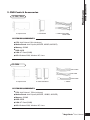
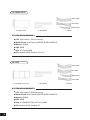
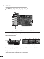
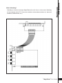
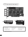
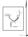
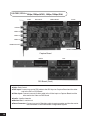
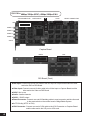
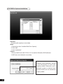
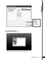
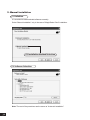
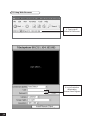
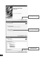
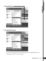
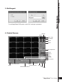
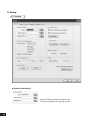
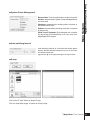
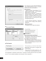
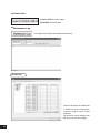
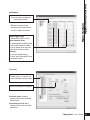
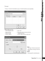
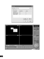
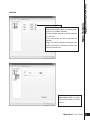
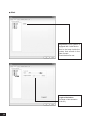
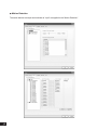
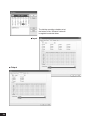
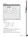
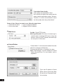
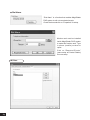
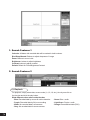
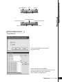
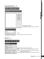
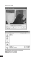
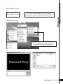
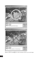
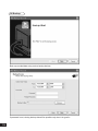
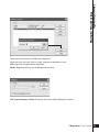
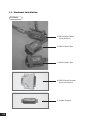
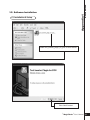
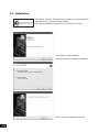
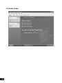
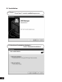
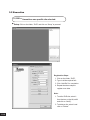
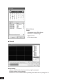
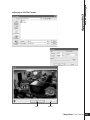
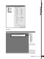
Table of Contents 1 Hardware Installation 5 3 Main System Application 37 1. Product Specification 6 1. Startup Screen 38 2. DVR Cards & Accessories - T04/TS04 - CS04 - CS08/CS16 - LS16 - CD08/CD16 - LD16 7 7 7 8 8 9 9 2. Login 38 3. Exit/Logout 39 4. Control Screen 39 5. Setup - System ·System Information ·System Power Management ·Auto Switching Interval ·E-Map ·TV-out ·On-Screen Display ·Text Inserter ·Hard Disk Usage ·I-Phone ·Version Info. ·Maintenance Log 40 40 41 41 41 41 43 44 44 45 45 46 46 3. Installation - T04 - TS04 - CS04 - CS08/CS16 - LS16 - CD08/CD16 - LD16 2 Software Installation 10 10 12 14 16 18 20 22 25 1. Automatic Installation - Definition - Installation Method Selection - Installing Drivers - DVR File System Installation - Completion & Retry 27 27 27 27 28 29 2. Manual Installation - Definition - Installation Method Selection - Software Selection 30 30 30 30 3. Remote Client Installation - Using MagicRadar S/W - Using the Web Browser 31 31 32 4.Uninstallation 35 5.Program Execution 35 - Device ·Camera ·Output Device ·Input Device ·Audio ·Alert 46 47 53 54 55 56 - Event ·Input ·Motion Detection ·No Video Signal 57 57 58 59 - Schedule ·Camera ·Input ·Output 59 59 60 60 - Network ·DVR Server ·Web Sever ·Central Station ·E-mail ·Dial Alarm 61 61 62 62 63 64 - User 64 4 View Log Application (Status) 67 1. Screen Features - Event Log 68 69 5 Playback Application (Search) 71 1. Search Features 1 72 2. Search Features 2 - Playback - Event/Object Search - Bookmark & Go To - Save - Print - Backup 72 72 73 75 75 79 80 6 Remote Monitoring System (Client) 83 1. Program Execution 84 Appendix 1 POS DVR 87 1. Hardware Installation - Parts - Installation 88 88 90 2. Software Installation - Installation & Setup 91 91 Appendix 2 I-phone 94 1. Installation 94 2. Execution 95 3. Audio Setup 96 Appendix 3 DVR Manager 98 1. Installation - Start - Selection of Installation Method - On Installing - Finish 98 98 98 99 99 2. Execution - DVR ·Setup ·Control ·Search 100 100 100 101 102 - MultiDVR ·Setup ·Control 104 104 105 - C & S (Central Station) ·Setup ·Event ·E-Map 106 106 107 107 Digital Video Surveillance System - MagicRadar Chaper 1 Hardware Installation > Product Specification > DVR Cards & Accessories > Installation 1. Product Specification Models Displaying Speed T04 / TS04 / CS04 / CS08 / CD08 / CS16 / CD16 / LS16 / LD16 30fps(NTSC), 25fps(PAL)/ 60, 50/120, 100/120, 100/240, 200/120, 100/240, 200/480, 400/480, 400 Recording Speed 30fps(NTSC), 25fps(PAL)/60, 50/120, 100/120, 100/240, 200/120, 100/240, 200/120, 100/240, 200 Video Inputs 4 / 4 / 4 / 8 / 8 / 16 / 16 / 16 / 16 Audio Inputs 1/2/4/4/8/4/8/4/8 Sensor Inputs 4 / 4 / 4 / 16 / 16 / 16 / 16 / 16 / 16 Alarm Outputs 2/2/4/8/8/8/8/8/8 Video Resolution Compression Type Supported Signal Types Supported Network Supported Backup Devices 640×480, 640×240, 320×240(NTSC) / 768×576, 768×288, 384×288(PAL) MPEG-4 NTSC, PAL TCP/IP, PSTN HDD, DVD/R, CD/RW, Network Driver, etc. C&B Tech-CND100200&SMART, Changzhou Minking-Minking, CTNCom-HD0670, Dong Yang Unitech-DSC230, DRAGON-DRAGON, Dynacolor-TPD7720, GeosanGRX1000, GOLDENEYE-GOLDENEYE, InterM-VRX2201, KALATEL-KTD312, Supported PTZ Protocols KJK-KJK, LG-LPTA100L, PELCO D&P, SAMSUNG-SCC641&SDZ160R& SPD1600&SPX1000&SPT1000, SONY-EVID3031, Vicon-Survey&2000, ZITECZITECH, etc. Operating Systems Supported Languages 6 Windows XP, Windows 2000, Linux English, Spanish, Japanese, French, Traditional Chinese, Simplified Chinese, Portuguese, Hebrew, Polish, German, Finnish, Greek, Hungarian, Korean, etc. Hardware Installation 2. DVR Cards & Accessories (1) T04 / TS04 a. Capture Card b. DIO Board c. Cables: DIO Cable Reset Cable SYSTEM REQUIREMENTS ● CPU: Intel Celeron 1GHz (minimum) ● Mother Board: Intel Chipset (845D/PE, 850B/D, 865G/PE) ● Memory: 256MB ● HDD: 80GB ● VGA: ATI Card (32MB) ● O/S: Windows 2000, Windows XP, Linux (2) CSO4 Video Cable DIO Cable Reset Cable a. Capture Card b. Video DIO Board c. Cables SYSTEM REQUIREMENTS ● CPU: Intel Celeron 1.7GHz (minimum) ● Mother Board: Intel Chipset (845D/PE , 850B/D, 865G/PE ) ● Memory: 256MB ● HDD: 80GB ● VGA: ATI Card (32MB) ● O/S: Windows 2000, Windows XP, Linux [ MagicRadar ] User’s Manual 7 (3) CS08 & CS16 Video Cable DIO Cable Reset Cable a. Capture Card b. DIO Board c. Cables SYSTEM REQUIREMENTS ● CPU: Intel Celeron 1.7GHz (minimum) ● Mother Board: Intel Chipset (845D/PE, 850B/D, 865G/PE) ● Memory: 256MB ● HDD: 80GB ● VGA: ATI Card (32MB) ● O/S: Windows 2000, Windows XP, Linux (4) LS16 Video Cable DIO Cable Reset Cable VGA Cable a. Live (Real Time) Card b. DIO Board SYSTEM REQUIREMENTS ● CPU: Intel Celeron 2.0GHz (Minimum) ● Mother Board: Intel Chipset (845D/PE, 850B/D, 865G/PE) ● Memory: 256MB ● HDD: 80GB ● VGA: ATI RADEON 7000 (VIP Port) (32MB) ● O/S: Windows 2000, Windows XP 8 c. Cables Video Cable DIO Cable Hardware Installation (5) CDO8, CD16 Reset Cable a. Capture Card (2 Boards) Master / Slave b. DIO Board c. Cables SYSTEM REQUIREMENTS ● CPU: Intel Pentium4 2.4GHz (minimum) ● Mother Board: Intel Chipset (845D/PE, 850B/D, 865G/PE) ● Memory: 256MB ● HDD: 80GB ● VGA: ATI Card (32MB) ● O/S: Win2000, Windows XP, Linux (6) LD16 Video Cable DIO Cable Reset Cable VGA Cable Sync. Cable a. Live (Real Time) Card (2 Boards) Master / Slave b. DIO Board c. Cables SYSTEM REQUIREMENTS ● CPU: Intel Pentium4 2.4GHz (minimum) ● Mother Board: Intel Chipset (845D/PE, 850B/D, 865G/PE) ● Memory: 256MB R-DRAM ● HDD: 80GB ● VGA: ATI RADEON 7000 (VIP Port) (32MB) ● O/S: Windows 2000, Windows XP [ MagicRadar ] User’s Manual 9 3. Installation (1) T04 >> 30fps/30fps (NTSC), 25fps/25fps (PAL) C B A D A. Camera Inputs B. TV-out C. DIO Cable Connector D. Reset Connector Connect one end of Watchdog cable to “D” and the other end to the reset switch on the mother board of MagicRadar System. G E2 F E1 E1 DIO Board (Side) C F1 F2 E2 G DIO Board (Front) E1. Sensor Inputs (⊕ only) E2. Sensor Input (⊖ only) F1&F2. Control Outputs G. Audio Input Put ⊕ cable into the hole of output device. Types of Output Devices: NC (Normal Close), NO (Normal Open) 10 Watchdog is a function that keeps MagicRadar alive at all times. In other words, Watchdog will automatically reboot PC if it becomes unstable or shows abnormal status (i.e. abnormal shutdown, Windows error, etc.) Hardware Installation What is Watchdog? [ MagicRadar ] User’s Manual 11 (2) TS04 >> 60fps/60fps (NTSC), 50fps/50fps (PAL) C B A D G E F E E1 F E2 G C DIO Board (Side) ▶ 12 DIO Board (Front) A. Camera Inputs D. Reset Connector F. Control Outputs B. TV-out E1.Sensor Inputs (⊕ only) G. Audio Inputs C. DIO Cable Connector E2.Sensor Input (⊖ only) For details, refer to page 10 & 11. Hardware Installation [ MagicRadar ] User’s Manual 13 (3) CS04 >>120fps/120fps (NTSC), 100fps/100fps (PAL) B C A D F E G2 H G1 B Audio Board C A. Camera Inputs D. Reset Connector G1. Sensor Inputs (⊕ only) B. Audio Cable Connector E. Audio Inputs G2.Sensor Input (⊖ only) C. DIO Cable Connector F. TV-out H. Control Outputs ▶ 14 DIO Board For details, refer to page 10 & 11. Hardware Installation [ MagicRadar ] User’s Manual 15 (4) CS08 / CS16 >>120fps/120fps (NTSC), 100fps/100fps (PAL) GAIN DIO INPUT VIDEO INPUT SYNC AUDIO1 AUDIO 2 AUDIO 3 AUDIO 4 MONITOR OUT RESET CONNECTOR Capture Board VIDEO DIO DIO Board (Front) ●Gain: Gain Control ●DIO Input: Connect one end of DIO cable to the DIO Input on Capture Board and the other end to the DIO on DIO Board. ●Video Input: Connect one end of video cable to the Video Input on Capture Board and the other end to the Video on DIO Board. ●Audio: 4 audio channels. ●Monitor Out: 1 monitor out. ●Reset Connector: Connect one end of Watchdog cable to reset connector and the other end to the reset switch on the mother board of MagicRadar System. 16 Hardware Installation [ MagicRadar ] User’s Manual 17 (5) LS16 >> 480fps/120fps (NTSC), 400fps/100fps (PAL) VGA CONNECTOR AUDIO 1 VIDEO INPUT A SYNC RESET CONNECTOR DIO INPUT AUDIO 2 AUDIO 3 AUDIO 4 SVHS Capture Board VIDEO DIO DIO Board (Front) ●DIO Input: Connect one end of DIO cable to the DIO Input on Capture Board and the other end to the DIO on DIO Board. ●Video Input: Connect one end of video cable to the Video Input on Capture Board and the other end to the Video on DIO Board. ●SYNC: Not in use ●Audio: 4 audio channels ●SVHS: 1 SVHS output ●Reset Connector: Connect one end of Watchdog cable to reset connector and the other end to the reset switch on the mother board of MagicRadar System. ●A: FPGA chip (NTSC or PAL) ●VGA Connector: Connect one end of VGA cable to the VGA Connector on Capture Board and the other end to the VIP port on VGA card. 18 Hardware Installation [ MagicRadar ] User’s Manual 19 (6) CD08 / CD16 >> 240fps/240fps (NTSC), 200fps/200fps (PAL) DIO INPUT VIDEO INPUT SYNC Slave Board AUDIO 1 AUDIO 2 AUDIO 3 AUDIO 4 Master Board MONITOR OUT RESET CONNECTOR VIDEO DIO DIO Board ●DIO Input: Connect one end of DIO cable to the DIO Input on Master Board and the other end to the DIO on DIO Board. ●Video Input: Connect one end of video cable to the Video Input on Slave Board, the middle to the Video Input on Master Board and the other end to the Video on DIO Board. ●SYNC: Not in use ●Audio: 8 audio channels ●Monitor Out: 2 monitor outs. ●Reset Connector: Connect one end of Watchdog cable to the reset connector and the other end to the reset switch on the mother board of MagicRadar System. 20 Hardware Installation [ MagicRadar ] User’s Manual 21 (7) LD16 >> 480fps/240fps (NTSC), 400fps/200fps (PAL) VGA CONNECTOR VIDEO INPUT SYNC RESET CONNECTOR DIO INPUT AUDIO Master Board SVHS DIO INPUT VIDEO INPUT SYNC Slave Board AUDIO MONITOR OUTPUT RESET CONNECTOR VIDEO DIO ●DIO Input: Connect one end of DIO cable to the DIO Input on Master Board and the other end to the DIO on DIO Board. ●Video Input: Connect one end of video cable to the Video Input on Slave Board, the middle to the Video Input on Master Board and the other end to the Video on DIO Board. ●SYNC: Connect one end of SYNC cable to the SYNC on Master Board and the other end to the SYNC on Slave Board. ●Reset Connector: Connect one end of Watchdog cable to reset connector and the other end to the reset switch on the mother board of MagicRadar System. ●VGA Connector: Connect one end of VGA cable to the VGA Connector on Master Board and the other end to the VIP port on VGA card. 22 Hardware Installation [ MagicRadar ] User’s Manual 23 Digital Video Surveillance System - MagicRadar Chaper 2 Software Installation > Automatic Installation > Manual Installation > Remote Client Installation > Uninstallation > Program Execution Steps: 1. Insert MagicRadar S/W. 2. Double-click “magicradar(3.5.0.0).exe”. ↓ 26 (1) Definition It is a method to install all the relevant softwares automatically. Select “Automatic Installation” at all times unless only “MagicRadar Client” is to be installed. Software Installation 1. Automatic Installation (2) Installation Method Selection (3) Installing Drivers [ MagicRadar ] User’s Manual 27 (4) DVR File System Installation Definition: Occupying disk capacity to record data Steps: 1. Select drives from “Available Disk Drive Capacity” 2. Click “Add”. 3. Click “Initialization”. Caution: 1. Be very careful not to add “C Drive”, for it is used for O/S and the DVR softwares. 2. HDD has to be initialized to record data Selecting “Quick Initialization” will lead to the initialization of entire disk capacity added. Otherwise, put in desirable number to initialize. Note that the number can not exceed total capacity added. 28 Software Installation Initialization process will be performed automatically. Click “Close” upon completion. (5) Completion & Retry Retry the entire procedure if an error message is displayed. [ MagicRadar ] User’s Manual 29 2. Manual Installation (1) Definition It is a method to install selected softwares manually. Select “Manual Installation” only in the case of “MagicRadar Client” installation. (2) Installation Method Selection (3) Software Selection Note: The rest of the procedures are the same as “Automatic installation”. 30 Software Installation 3. Remote Client Installation (1) Using MagicRadar S/W Double click “magicradar(3.5.0.0), exe”. Select “Manual Installation”. Select “MagicRadar DVR Client” only. [ MagicRadar ] User’s Manual 31 (2) Using Web Browser 1. Type in the IP address of DVR server. 2. Log in first before downloading Remote Client Program. 32 Software Installation 3. Click the “Install Remote Client” button for downloading. 4. Downloading in progress [ MagicRadar ] User’s Manual 33 5. Click “Next” to proceed. 6. Select “Manual Installation”. 7. Click “Next” to finish Installation process. 34 Software Installation 4. Uninstallation 5. Program Execution Find the icons on the desktop to execute “MagicRadar DVR” and “MagicRadar DVR Client”. Or find “MagicRadar DVR” under “All Programs”. [ MagicRadar ] User’s Manual 35 Digital Video Surveillance System - MagicRadar Chaper 3 Main System Application > Startup Screen > Login > Exit / Logout > Control Screen > Setup (System/Device/Event/Schedule/Network/User) 1. Startup Screen The above screen will appear as MagicRadar DVR system starts. 2. Login The default values for User and Password are “admin” and “no password”. Click “OK” to execute MagicRadar DVR system. To give “admin” a password and to create new users, certain configurations are required(Setup/User). Only “admin” and users with appropriate authorization have access to the Setup menu. Note: Vertual keypad is available wherever typing is required. 38 Main System Application(Control) 3. Exit/Logout To end MagicRadar DVR system, select “Exit” and type in password. 4. Control Screen Network Setup Date / Time User Mode Model Adjust PTZ Adjustment Preset Touring Light E-map I-Phone PTZ Control Camera Layout Panel Power Volum Camera Selection Manual Output Panel Control Status Serch [ MagicRadar ] User’s Manual 39 5. Setup (1) System ● System Information Create a DVR name and put in admin. info. They will be displayed on outgoing e-mails. 40 Reserved time: Time set to shut down or to reboot computer Disable: selected when System Power Management is not to be used Shutdown: selected when shutting down computer is required at the time set Reboot: selected when rebooting computer is required at the time set Exit & Turn off Computer: By checking the box, computer will be turned off automatically as a user exits from MagicRadar DVR system. Main System Application(Control) ● System Power Management ● Auto-switching Interval Auto-switching Interval is a function that allows green square around selected camera to move to the next one at the interval set. e.g.) Camera1 10 sec. Camera2 10 sec. Camera3…. ● E-map Click on the “E-map” button to design E-map. Click on “Open Map Image” to select an E-map image. [ MagicRadar ] User’s Manual 41 ↓ The above is a designed E-map sample. Drag mouse to position Camera/Input/Output and design E-map. 42 Main System Application(Control) Click on the E-map button positioned next to the I-phone button to open E-map. White Camera : Not on Recording, Yellow Camera: On Recording, White Input/White Output : Not Activated, Yellow Input/Yellow Output: Activated ● TV-OUT TV-OUT is a function that sends selected cameras to a call monitor (external analog monitor). Click on the “TV-OUT” button for setup. [ MagicRadar ] User’s Manual 43 The models such as CD (240FPS/240FPS) & LD16 (480FPS/240FPS) support 2 TV-OUTs and the rest of the models support 1. Setup Options : 1. Same as Server Screen Mode ( For LS (480FPS/120FPS) only) - TV-OUT Monitor displays what’ s on DVR server. Manual Channel Selection - Channels are selected manually. Once “Manual Channel Selection” is selected, channels can also be selected manually on Control screen by placing mouse on camera picture and clicking the right mouse. 2. Auto Channel Switching - Selected channels rotate to display at the switching interval set. Switching Interval: The length of time to stay at one camera ● On-screen Display Show Camera Names and Status : By checking it, camera names and status will be displayed on camera pictures. ● Text Inserter Show Motion Detection Blocks : By checking it, green motion detection blocks will be displayed on camera pictures when recording schedule is set as “M” (Setup/Schedule). Text Inserter is a function that allows MagicRadar DVR system to integrate with POS machines. Simply install “text_inserter_plugin_for_ pos” on DVR Server, and transactions that occur will be displayed on selected camera pictures. Transaction recording and text search are possible as well. For more detailed installation and information. Refer to Appendix 1. 44 Hard Disk Usage is to select data storage method. If “Once” is selected, data will be stored up to the point where HDD reaches its maximum capacity. If “Recycle” is selected, data will be overwritten from the point HDD reaches its maximum capacity based on “First In First Out”. ● I-Phone I-phone is “Two-Way Audio Communication”. Check the box, go to Control Screen, and click on the I-phone button for audio communication. For more detailed I-phone setup, refer to Appendix 2. Main System Application(Control) ● Hard Disk Usage Port No.: The port number for I-phone use has to be set up. Normally the default value is good to use. Timeout: It indicates the maximum length of connection trial. If there is no response within the value set, call will be cancelled. [ MagicRadar ] User’s Manual 45 ● Version Info. Version 3.5.0.0: version name Built 2004. 8. 4: built date ● Maintenance Log It is used to record and view maintenance history. (2) Device Device sub-screen is divided into 5 different setup categories; Camera, Output, Input, Audio and Alert. All devices in each category can be set up on one same page. 46 Cameras will be enabled by checking the boxes. Different resolutions and recording frame rates can be set up for different cameras. Video Signal Type: Select either NTSC or PAL. Auto Channel Scan: It automatically identifies all the active video channels. Make sure to always click and scan after S/W version change. Default: It sets “Event Recording Frame” and “Recording Frame” as default values. Main System Application(Control) ● Camera [Camera] Double-click on “Camera” for more individual Camera setup. Select recording picture quality. Pre-alarm (max. 10 sec.): Length of time to be recorded before event Post-alarm (max. 60 sec.): Length of time to be recorded after event [ MagicRadar ] User’s Manual 47 [Motion Detection] MagicRadar DVR system is designed to have unlimited motion detection zones and to have different motion detection sensitivity levels. Zone Settings: 1. Select “Set”, drag mouse to set motion detection zones and click “OK”. 2. Select “Clear” to clear certain areas inside motion detection zones. 3. Click on “Clear All” to clear all the motion detection zones. [PTZ Camera Setup] When using a PTZ camera, check the box and select a model name. MagicRadar DVR system supports nearly 40 different protocols. Camera ID: Leave it as it is if only one PTZ camera is used. Otherwise, give each camera a different number. Select the port used for PTZ cmera. Bit per Second: It is 9600 for most of PTZ cameras. But a few can have different values. Refer to camera manual. Apply All: The same settings will be applied to the rest of the cameras by clicking on “Apply All”. 48 Either click the right mouse on camera picture or click on the Preset (Touring) button for Preset (Touring) setup and use. Main System Application(Control) [Preset & Touring] [Preset] “Preset” is a function that enables a camera to move from one position to another automatically. [ MagicRadar ] User’s Manual 49 Steps to Set up Presets: 1. Move camera to a desired position using the PTZ Control on Control screen. 2. Click the right mouse. 3. Name the preset. 4. Repeat the above for setting up as many as 256 presets. 5. Click the right mouse to run preset and click the “Auto” button to stop it. 50 “Touring” is a function that enables a group of selected presets to work repeatedly. Steps to Set up a Tour: 1. Click the right mouse. 2. Name the tour. 3. Click on “Add”. 4. Select a preset. Main System Application(Control) [Touring] 5. Click “OK”. 6. Repeat the above to have more than 1 preset in the tour. 7. Click the right mouse to run the tour. Dwell: The length of time that camera will pause before moving to the next preset. Speed: Moving speed for selected preset. [ MagicRadar ] User’s Manual 51 52 MagicRadar DVR system can be equipped with as many as 8 output devices. Simply check the boxes for use. In addition, outputs can be manually activated from Control screen (Manual Alarm). Main System Application(Control) ● Output Device Double-click on “Output” for individual output setup. Name: Output device name. Length of Activation: The length of output activation (1-60 sec.). Length of Standby: The length of output deactivation until reactivation (0-60 sec.). Apply All: The same settings will be applied to the rest of the output devices. [ MagicRadar ] User’s Manual 53 ● Input Device MagicRadar DVR system can be equipped with as many as 16 input devices. Simply check the boxes for use. Each and every input can be tuned independently. Signal Types: NO: (+) & (-) detached normally NC: (+) & (-) attached normally 54 MagicRadar DVR system is equipped with as many as 8 audio channels. Simply connect cameras to audio channels for use, and audio recording will be completed as chosen. (e.g.) The above selections indicate that Audio2 will record Camera3, Audio3 will record Camera5, etc. Main System Application(Control) ● Audio Input Gain (1-15): It is audio level control similar to volume control. [ MagicRadar ] User’s Manual 55 ● Alert MagicRadar DVR system is equipped with 1 alert device. Alert is the beep inside the system that sounds in the case of event. Check the box for use. Length of Activation: The length of alert activation (1-60 sec.). 56 “Event” consists of 3 different groups; “Input”, “Motion Detection” and “No Video Signal”. On this menu, devices can be set to respond to different events. ● Input Main System Application(Control) (3) Event Length of Full Screen Display: The time length for full screen display in the case of input device activation. Full Screen Display Channels: Camera channels to be full-screen displayed. Link to Recording: One Input device can have as many as 16 recording cameras on activation. The below example shows that Camera1 will record in the case of Input1 activation. Link to Output: One Input device can have as many as 8 activating output devices on activation. The above example shows that Output1 will be activated in the case of Input1 activation. Link to Alert: Input device can also be linked to alert. [ MagicRadar ] User’s Manual 57 ● Motion Detection The same identical concepts and methods as “Input” are applied to the “Motion Detection”. 58 The same identical concepts and methods as “Input” are applied to “No Video Signal”. The above example shows that Camera2 will take over and record if there is a signal cut in Camera1. Main System Application(Control) ● No Video Signal (4) Schedule “Schedule” is a place where the different activities of different devices are determined. ● Camera Each camera can have different recording options; scheduled recording by time & day and selective recording. R: Recording at all times M: Recording only on motion detection S: Recording only on sensor detection H: Recording at all times and higher frame recording on sensor/motion detection [ MagicRadar ] User’s Manual 59 The holiday recording schedule set at the bottom of the “Schedule” table will be applied to selected dates. ● Input ● Output 60 Main System Application(Control) (5) Network ● DVR Server Supported Network: 1. TCP/IP - Connecting to DVR Server from Client using Lan or DSL 2. PSTN - Connecting to DVR Server from Client using PSTN or ISDN modem 3. None - Not allowed to connect to DVR Server remotely Port No.: The default port number is 9091. Timeout: The time length of trials to connect to DVR Server from Client Maximum Users: The maximum number of users that can be logged in remotely. [ MagicRadar ] User’s Manual 61 Transmitted Video Quality: Video quality to be transmitted to Client. As a reminder, the higher video quality gets, the slower network transmission speed becomes. Therefore, it is often recommended to select low video quality when using “Narrowband”. Router in Use: If there is a router in use, follow the steps below: 1. Check the box above. 2. Type in router’s IP address. 3. Go to router setup 4. Register DVR’s IP address. ● Web Server Port No.: Fixed HTTP Port No. Web Login Required: If the box is checked, login is required when connecting DVR server using web browser. If the box is NOT checked, automatic login as “anonymous” will be done. ● Central Station “Central Station” is a function that enables Client with static IP to manage multi DVR sites. Check the box and click on “Properties” for setup. Note: “DVR Manager” must be installed on Central Station Server(Client). For more details, refer to Appendix 3. Type in the IP address of Central Station Server (Client with Static IP) and click on “Reported Events” for more setup. 62 Main System Application(Control) Choose events to report to Central Station server and set reporting time period. ● E-mail E-mail is a function that enables MagicRadar DVR system to send out e-mails when selected events occur. Check the box and click on “Properties” for setup. Make sure to put in the right IP address of SMTP server. Then, click on “Reported Events” for more setup. The “Reported Events” menu is the same as Central Station. [ MagicRadar ] User’s Manual 63 ● Dial Alarm “Dial Alarm” is a function that enables MagicRadar DVR system to call out on selected events. Check the box and click on “Properties” for setup. Modem card must be installed inside MagicRadar DVR system to make this function work. Type in phone (mobile) number to report. Click on “Reported Events” (same setup as Central Station) for more setup. (6) User 64 Main System Application(Control) Authorized Access: Checked functions will be allowed to access remotely. Accessible Channels: Checked channels will be allow to view remotely. Control Level: The lowest number will be allowed to have the first priority to set up, control, etc remotely. Admin Mode: A user who can go into the setup and program (given the same authorization as “Admin”). Only ONE user with “Admin Mode” can log in remotely. Network: If checked, remote access authorization will be given. Multi-access: If checked, multi-users with the same user name can log in remotely at the same time. [ MagicRadar ] User’s Manual 65 Digital Video Surveillance System - MagicRadar Chaper 4 View Log Application > Screen Features - Event Log 1. Screen Features Recording Camera: It shows recording status. Sensor Detection: It shows sensor detection status. Motion Detection: It shows motion detection status. Alarm: It shows alarm activation status. HDD Capacity: It shows HDD capacity used for recording. Event: It shows events occurred. Event Log: It shows all the previous events occurred by date. 68 View Log Application(Status) (1) Event Log Date: All dates with events will be marked in bold numbers. List: All events for a certain selected date will be shown. Delete All: If clicked, all the previous records will be deleted. Delete: If clicked, only the events for a certain selected date will be deleted. Refresh: If clicked, events will be updated. [ MagicRadar ] User’s Manual 69 Digital Video Surveillance System - MagicRadar Chaper 5 Playback Application > Search Features 1 > Search Features 2 - Playback - Event / Object Search - Bookmark & Go To - Save - Print - Backup 1. Search Features 1 Calendar: All dates with recorded data will be marked in bold numbers. Blur/Sharp/Normal: Buttons to adjust sharpness of image Zoom: Buttons to zoom in/out Brightness: buttons to adjust brightness Contrast: buttons to adjust contrast Default: Default for Zoom/Brightness/Contrast 2. Search Features 2 (1) Playback For playback, simply select date, screen mode (1, 4, 9, 16, etc.), time by one click on the time bar and click the play button. What different colors mean on the time bar: ·Blue: Recorded data by sensor & motion detection ·Green: Blue + audio ·Light Green: Purple + audio ·Purple: Recorded data by 24-hour-recording ·Orange: Recorded text data (POS) ·White: No recorded data in all cameras ·Gray: No recorded data for some cameras 72 Stop Play Backward Play×2 Play Event/Obiect Search Move to the First Data Move 1 Frame Backward Move to the Last Data Move 1 Frame Forward View Log Application(Search) Play Backward×2 (2) Event/Object Search [Event Search] Click the Event/Object Search button and select “Event”. Select channels for Event Search. Select one event from the event list and click “OK”, and the selected event will be displayed. Click “Refresh” to update the list. [ MagicRadar ] User’s Manual 73 [Object Search] Object Search is only to search certain selected objects for a certain period of time. Scan: Set the time period for object search. Motion Detection Zone: Select “Set” and mark areas by dragging mouse. “Clear” is used to erase certain areas inside motion detection zones. Sensitivity: It means “Motion Detection Sensitivity”. Display Motion Detection: If checked, green motion detection blocks will be displayed. Clear All: Click on it to clear all the motion detection zones set. 74 View Log Application(Search) (3) Bookmark & Go To Bookmark (Favorites): Added data from “Object Search” are stored here. Go To: Select desired time to search and click “OK”. (4) Save AVI: For saving motion pictures and audio BMP: For saving images. Watermarked images can be saved. JPEG: For saving regular still images. Quality is not as good as BMP but less HDD is used. Save in JPEG with Time Period: For scheduled save in JPEG [ MagicRadar ] User’s Manual 75 [Save in AVI Format] Click “Start” to start saving and “Stop” to stop saving. Mute: Saving video only (no audio) High Speed: Saving in high speed 76 [Save in BMP Format] ⇨ Click “Start” and select “BMP” as you save images. Saved images can be checked using “Watermark Proofer”. [Watermark Proofer] View Log Application(Search) [Save in BMP Format] Execute“Watermark Proofer”and check if certain saved images are forged or not. [ MagicRadar ] User’s Manual 77 [Save in JPEG Format] رClick “Start” and select “JPEG” as you save images. 78 View Log Application(Search) [Save in JPEG with Time Period] رSelect time period and select channels to be saved in JPEG. (5) Print Click the “Print” button and follow the same printing procedure as you would normally print out documents. [ MagicRadar ] User’s Manual 79 (6) Backup Back up recorded data using various backup devices. If password is set, viewing backup data will be possible only when it is typed in. 80 View Log Application(Search) [ MagicRadar ] User’s Manual 81 Digital Video Surveillance System - MagicRadar Chaper 6 Remote Monitoring System > Program Execution 1. Program Execution Double-click on the “MagicRadar DVR Client” icon on the desktop to execute Remote Monitoring System (Client). Note: Make sure to put the same Port No. as DVR server. 84 Remote Monitoring System(Client) There can be more than one DVR server registered. Select one from “Servers”, click on “Login” and type in password to log in. Edit: Login info. changes can be made here. Delete: Registered servers can be deleted with one click. Full Screen Display on Event: If checked, full screen will be displayed on events. [ MagicRadar ] User’s Manual 85 Digital Video Surveillance System - MagicRadar Appendix POS DVR > Hardware Installation > Software Installation I-phone > Installation > Execution > Audio Setup DVR Manager > Installation > Execution 1-1. Hardware Installation (1) Parts a. RS232 Serial Cables (Cross & Direct) b. RS232 Serial Cable c. RS232 Serial Cable d. RS232 Serial Converter (9 pins into 25 pins) e. Gender Changer 88 Appendix 1 POS DVR f. a + d + e g. DVR h. POS Printer i. Point of Sales (POS) [ MagicRadar ] User’s Manual 89 (2) Installation ▶“b” goes into the COM Port 1 of “g”. ▶“a” goes into the serial port of “h”. ▶“c” goes into the serial port of “i”. 90 Appendix 1 POS DVR 1-2. Software Installation (1) Installation & Setup Install “text_inserter_plugin_for_pos” on DVR Server. Click “Next” to start. [ MagicRadar ] User’s Manual 91 Select “Typical Installation” for automatic installation. Select camera channels and click the com port buttons for serial port configuration. Make sure to select “COM1” if POS printer is connected to com port 1. The Baud rate value is normally 9600. 92 Appendix 1 POS DVR Click “Finish” to complete. Go to “Text Inserter” in the DVR setup and choose different fonts and different display corners. [ MagicRadar ] User’s Manual 93 2-1. Installation Any system used for “Two-way Communication” must have static IP and “iphone(1.0.1.0).exe” must be installed. For I-phone installation, double-click on “iphone(1.0.1.0).exe”. Click “Next” to start installation process and select “Automatic Installation”. Click “Finish” to complete the process. 94 Appendix 2 I-phone 2.2 Execution Go to “Start”, “All Programs”, find “I-phone” and select it for execution. Find the I-phone icon at the right bottom and click it for the next step. Select “Call” for Two-Way “Communication”, type in IP address and click “Connect”. Property : The default port number is 8015 and the default timeout value is 5 seconds. Leave them as they are unless other values must be used. [ MagicRadar ] User’s Manual 95 2.3 Audio Setup 96 Appendix 2 I-phone Go to “Control Panel”, “Sounds, Speech and Audio Devices” and “Sounds and Audio Devices”. Then, go to “Audio”, “Sound playback” and click “Volume”. Recording Control should be set up this way. [ MagicRadar ] User’s Manual 97 3.1 Installation (1) Start >> Click “Next” to start installation process. (2) Selection of Installation Method >> Select “Automatic Installation” 98 Appendix 3 DVR Manager (3) On Installing (copying drivers and files) (4) Finish >> Click “Finish” to complete. [ MagicRadar ] User’s Manual 99 3.2 Execution (1) DVR >> It monitors one specific site selected. ● Setup: Click on the folder, “DVR” and click on “Setup” to proceed. Registration Steps: 1. Click on the folder, “DVR”. 2. Type in all the required info. 3. Click “Add Site” for completion. 4. Repeat the above steps to register more sites. Note: 1. To edit a DVR site, select it from the tree on the left, edit it and click on “Notify”. 2. To delete a site, select it and click on “Delete”. 100 Appendix 3 DVR Manager Checked events will be reported to DVR Manager and recorded in Event Log. ● Control Simply double-click on DVR site name to connect. [ MagicRadar ] User’s Manual 101 Manual Alarm Setps: 1. Set alarms on the DVR Server. 2. Monitor on DVR Manager. 3. Detect event. 4. Click alarm button. ● Search Search Steps: 1. Select a DVR site from the tree at the top right for playback. 2. Select a date from the calendar. 3. Select time to be searched either by clicking on the time bar or by using “Go To”. 102 Appendix 3 DVR Manager ● Saving in AVI File Format Stop Cancel [ MagicRadar ] User’s Manual 103 (2) MultiDVR >> It monitors as many as 32 cameras from different DVR sites. ● Setup: Click on the folder, “DVR” and click on “Setup” to proceed. Registration Steps: 1. Click on the folder, “MultiDVR”. 2. Type in all the required info. 3. Click on “Camera/Event”. 4. Select cameras to monitor. 5. Click on “Apply”. 6. Repeat the above steps to register as many as 32 cameras. 104 Appendix 3 DVR Manager ● Control Double-click on the folder, “MultiDVR” to view registered cameras. [ MagicRadar ] User’s Manual 105 (3) C & S (Central Station) >> It manages events received from numerous DVR sites. ● Setup On each DVR server, go to “Setup/Network” and check the box next to “Central Station” Then, type in the IP address of DVR Manager and select events to report. On DVR Manager, click on the button, “C&S”, and registered DVRs will be seen on E-Map. Click on “Setup” for port setup. The default value, 9100 is good to use in all cases. 106 Appendix 3 DVR Manager ● Event “Event” displays all the events coming in from registered DVRs. Double-click on event to go to DVR server. ● E-Map Click on “Mag” to configure E-Map. To create an E-Map image, click on the right mouse and select “Open E-Map”. Only BMP file can be in use. [ MagicRadar ] User’s Manual 107 Click on the right mouse and select “Camera Lock” to be able to position DVRs at desired locations. Click on the right mouse and select “Save Setting” to save image and camera locations. After configuration, selected E-Map image and all DVR sites at selected locations can be viewed. To visit a certain DVR site using E-Map, click on “Mag” and doubleclick on the site (camera-shaped symbol). Any DVRs (cameras) blinking in red and blue have events happening. 108 Appendix 3 DVR Manager Restricting incoming events and receiving only desired events can be done regardless of DVR setup. On E-Map, click on the right mouse and select “Property”. Only checked events will be reported to C&S. Click on “All Apply” to give the same conditions to all the rest of the DVR sites. [ MagicRadar ] User’s Manual 109


![[Proxyview]User`s Manual (5.1.4.0)](http://vs1.manualzilla.com/store/data/005658349_1-e7f841297d622d23913e7f3fcabf599d-150x150.png)