1
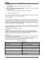
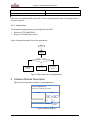
The following document contains information on Cypress products. Colophon The products described in this document are designed, developed and manufactured as contemplated for general use, including without limitation, ordinary industrial use, general office use, personal use, and household use, but are not designed, developed and manufactured as contemplated (1) for any use that includes fatal risks or dangers that, unless extremely high safety is secured, could have a serious effect to the public, and could lead directly to death, personal injury, severe physical damage or other loss (i.e., nuclear reaction control in nuclear facility, aircraft flight control, air traffic control, mass transport control, medical life support system, missile launch control in weapon system), or (2) for any use where chance of failure is intolerable (i.e., submersible repeater and artificial satellite). Please note that Spansion will not be liable to you and/or any third party for any claims or damages arising in connection with above-mentioned uses of the products. Any semiconductor devices have an inherent chance of failure. You must protect against injury, damage or loss from such failures by incorporating safety design measures into your facility and equipment such as redundancy, fire protection, and prevention of over-current levels and other abnormal operating conditions. If any products described in this document represent goods or technologies subject to certain restrictions on export under the Foreign Exchange and Foreign Trade Law of Japan, the US Export Administration Regulations or the applicable laws of any other country, the prior authorization by the respective government entity will be required for export of those products. Trademarks and Notice The contents of this document are subject to change without notice. This document may contain information on a Spansion product under development by Spansion. Spansion reserves the right to change or discontinue work on any product without notice. The information in this document is provided as is without warranty or guarantee of any kind as to its accuracy, completeness, operability, fitness for particular purpose, merchantability, non-infringement of third-party rights, or any other warranty, express, implied, or statutory. Spansion assumes no liability for any damages of any kind arising out of the use of the information in this document. ® ® ® TM Copyright © 2013 Spansion Inc. All rights reserved. Spansion , the Spansion logo, MirrorBit , MirrorBit Eclipse , TM ORNAND and combinations thereof, are trademarks and registered trademarks of Spansion LLC in the United States and other countries. Other names used are for informational purposes only and may be trademarks of their respective owners. MCU-AN-510043-E-11 32-BIT MICROCONTROLLER MB9B610T SERIES MB9BF618 EVALUATION BOARD ETHERNET SOFTWARE USER MANUAL ARM and Cortex-M3 are the trademarks of ARM Limited in the EU and other countries. Revision History Revision History Version Date Updated by Approved by Modifications 1.0.0 2012-3-28 FSS Initial version 1.1.0 2012-5-28 FSS Add dual port demo, remove the PPPoE demo. Specifications are subject to change without notice. For further information please contact each office. All Rights Reserved. The contents of this document are subject to change without notice. Customers are advised to consult with sales representatives before ordering. The information, such as descriptions of function and application circuit examples, in this document are presented solely for the purpose of reference to show examples of operations and uses of FUJITSU SEMICONDUCTOR device; FUJITSU SEMICONDUCTOR does not warrant proper operation of the device with respect to use based on such information. When you develop equipment incorporating the device based on such information, you must assume any responsibility arising out of such use of the information. FUJITSU SEMICONDUCTOR assumes no liability for any damages whatsoever arising out of the use of the information. Any information in this document, including descriptions of function and schematic diagrams, shall not be construed as license of the use or exercise of any intellectual property right, such as patent right or copyright, or any other right of FUJITSU SEMICONDUCTOR or any third party or does FUJITSU SEMICONDUCTOR warrant non-infringement of any third-party's intellectual property right or other right by using such information. FUJITSU SEMICONDUCTOR assumes no liability for any infringement of the intellectual property rights or other rights of third parties which would result from the use of information contained herein. The products described in this document are designed, developed and manufactured as contemplated for general use, including without limitation, ordinary industrial use, general office use, personal use, and household use, but are not designed, developed and manufactured as contemplated (1) for use accompanying fatal risks or dangers that, unless extremely high safety is secured, could have a serious effect to the public, and could lead directly to death, personal injury, severe physical damage or other loss (i.e., nuclear reaction control in nuclear facility, aircraft flight control, air traffic control, mass transport control, medical life support system, missile launch control in weapon system), or (2) for use requiring extremely high reliability (i.e., submersible repeater and artificial satellite). Please note that FUJITSU SEMICONDUCTOR will not be liable against you and/or any third party for any claims or damages arising in connection with above-mentioned uses of the products. Any semiconductor devices have an inherent chance of failure. You must protect against injury, damage or loss from such failures by incorporating safety design measures into your facility and equipment such as redundancy, fire protection, and prevention of over-current levels and other abnormal operating conditions. Exportation/release of any products described in this document may require necessary procedures in accordance with the regulations of the Foreign Exchange and Foreign Trade Control Law of Japan and/or US export control laws. The company names and brand names herein are the trademarks or registered trademarks of their respective owners. Copyright © 2011 Fujitsu Semiconductor Limited Asia All rights reserved. MCU-AN-510043-E-11 – Page 2 Contents Contents REVISION HISTORY ............................................................................................................ 2 CONTENTS .......................................................................................................................... 3 1 INTRODUCTION .............................................................................................................. 5 1.1 Purpose ................................................................................................................... 5 1.2 Definitions, Acronyms and Abbreviations ................................................................ 5 1.3 Reference Documents ............................................................................................. 5 2 HARDWARE ENVIRONMENT ......................................................................................... 6 3 DEVELOPMENT ENVIRONMENT ................................................................................... 7 4 FEATURES ...................................................................................................................... 8 4.1 Overview ................................................................................................................. 8 4.2 Subsystem Function Description ............................................................................. 9 4.2.1 Send task & Receive task ........................................................................ 10 4.2.2 TCP/IP task ............................................................................................. 10 4.2.3 Applications ............................................................................................. 11 5 SOFTWARE MODULE DESCRIPTION ......................................................................... 11 5.1 LwIP-Ethernet I/F (Porting LwIP to MB9BF618S/T) ............................................... 12 5.2 LwIP-RTOS I/F (Porting lwIP to uC/OS-II) ............................................................. 12 5.3 Porting RTOS to MB9BF618S/T ............................................................................ 14 6 DEMO APPLICATIONS ................................................................................................. 14 6.1.1 System Files Structure ............................................................................. 14 6.1.2 ICMP ....................................................................................................... 14 6.1.3 Dual Ethernet port demo .......................................................................... 15 6.1.4 DHCP client ............................................................................................. 16 6.1.5 Http server ............................................................................................... 17 6.1.6 UDP echo server ..................................................................................... 18 6.1.7 TCP echo server ...................................................................................... 19 7 FUNCTION ..................................................................................................................... 21 7.1 Function List .......................................................................................................... 21 7.2 Global Data ........................................................................................................... 23 7.3 Global Timer.......................................................................................................... 23 7.4 Event ..................................................................................................................... 23 7.5 Macro Define ......................................................................................................... 24 MCU-AN-510043-E-11 – Page 3 Contents 8 ADDITIONAL INFORMATION ....................................................................................... 26 MCU-AN-510043-E-11 – Page 4 Chapter 1 Introduction 1 Introduction 1.1 Purpose This document describes the Ethernet feature of MB9BF618T/S, as well as presents a demonstration package based on a free TCP/IP stack, lwIP (lightweight IP). MB9BF618T/S microcontrollers are highly integrated 32-bit microcontrollers dedicated for embedded controllers with high-performance and competitive cost. MB9BF618T/S microcontrollers have a high-quality 10/100 Mbps Ethernet peripheral which supports both MII and RMII interface for external PHY device. 2 Ethernet ports can be used independently when using RMII mode. One of the advanced features of the Ethernet controller is the capability of generating, inserting and verifying the checksums of the IP, UDP, TCP and ICMP protocols by hardware. In this document, applications can be found using this feature. 1.2 Definitions, Acronyms and Abbreviations API Application Programming Interface I/F Interface EVB Evaluation board MII Media Independent Interface RMII Reduced Medium Independent Interface MAC Media Access Controller PHY Physical Layer lwIP Lightweight IP 1.3 Reference Documents [1].MB9Bxxx-MN706-00002-4v0-E.pdf [2].MB9BF616S-DS706-00014-0v01-E.pdf [3].MB9BF210T_610T-MN706-00015-1v0-E.pdf [4].MB9BF618S EV-Board Hardware Design Specification.doc [5]. (SPEC)FM3_618EVB-SystemReq_Ethernet.doc [6]. PPP OE spec RFC2516 [7]. PPP spec RFC166 [8]. Design and Implementation of the LWIP TCP/IP Stack, Feb,2001, Adam Dunkels. MCU-AN-510043-E-11 – Page 5 Chapter 2 Hardware Environment 2 Hardware Environment Hardware board FSSDC-9B618-EVB CPU Chip: Fujitsu MB9BF618S CPU Frequency: 144MHz; Ram Space: 128 K bytes; Code Space: 1 M bytes; MCU-AN-510043-E-11 – Page 6 Chapter 3 Development Environment 3 Development Environment Name Description Part Number Manufacture IAR EWARM Software Developing IDE V6.21 IAR J-link MCU Emulator J-link IAR MCU-AN-510043-E-11 – Page 7 Remark Chapter 4 Features 4 Features 4.1 Overview To demonstrate the Ethernet feature of MB9BF618T/S, the firmware consists of the following functions (figure 1 is the firmware architecture): Ethernet driver RTOS (uC/OS-II 2.86) TCP/IP stack (LwIP 1.3.2) Demo for HTTP,ICMP,DHCP Demo for TCP/UDP echo server Application Http server, DHCP client, TCP/UDP echo server ICMP, TCP, UDP Middleware IP layer (ip.c,ip_addr.c,ip_frag.c) ARP (etharp.c) Network Interface (netif.c,inet.c) Memory management (memp.c mem.c) Low level Ethernet interface (ethernetif.c ) Driver Ethernet driver (emac_fm3.c ,eth_fm3.c ) Figure1 firmware architecture MCU-AN-510043-E-11 – Page 8 RTOS (uC/OS-II) emulation layer (sys_arch.c) Chapter 4 Features The description of each module is listed in the table below. Table 1 Modules description Type Item Details Ethernet driver This is a driver for Ethernet MAC to receive and send package to PHY. It acts as an interface between MB9BF618T/S and PHY. Low level Ethernet interface This is a driver required by LwIP to access the network. It acts as an interface between Ethernet MAC and LwIP. Emulation layer The operating system emulation layer provides a uniform interface to operating system services such as timers, process synchronization, and message passing mechanisms. It acts as an interface between uC/OS-II and LwIP. LwIP The LwIP TCP/IP implementation is to reduce the RAM usage while still having a full scale TCP, which make LwIP suitable for use in embedded systems. uC/OS-II μC/OS-II is a priority-based pre-emptive real time multitasking operating system kernel for microprocessors, written mainly in the C programming language. It is mainly intended for use in embedded systems. Http server This demo shows an implementation of a web server. DHCP client This demo shows that the EVB adopts an IP address assigned by DHCP server running on the PC. TCP/UDP echo server This demo is used to test a basic TCP/UDP connection. The EVB acts as a TCP/UDP server that waits for client requests and echoes back whatever it has received. Drivers Middleware Application The demo applications are developed in 2 separate projects for ease of debugging and testing. 4.2 Subsystem Function Description There are at least four tasks are running in the applications, Receive task When triggered by the event of EMAC interrupt handler, the incoming package will be copied and passed to TCP/IP task for parsing. MCU-AN-510043-E-11 – Page 9 Chapter 4 Features Send task Get the package from TCP/IP task and send it out to MAC controller. TCP/IP task Parse the incoming package and pass the data to application layer or encapsulate the sending out package before passing it to send task. Application task This task will use APIs of LwIP to implement respective applications. 4.2.1 Send task & Receive task These two tasks are designed to switch the packages between the driver and TCP/IP stack. Mailbox and queue are used to synchronize the tasks. 4.2.2 TCP/IP task lwIP is a light-weight implementation of the TCP/IP protocol suite that was originally written by Adam Dunkels of the Swedish Institute of Computer Science (SICS) and licensed under the BSD license, now is being actively developed by a team of developers distributed worldwide headed by Leon Woestenberg . The development homepage has the latest news and releases: http://savannah.nongnu.org/projects/lwip/ . The task is dedicated to implement TCP/IP stack. LwIP parses and encapsulates the packages in this task. It should have higher priority than other tasks to ensure the process of incoming and outing packets. Three types of APIs are offered by lwIP stack: RAW API The RAW API is based on the native API of lwIP. It is used to develop callback-based applications. When initializing the application, the user needs to register call back functions to different core events (such as, TCP_Sent, TCP_error). The callback functions will be called from the lwIP core layer when the corresponding event occurs. Netconn API The netconn API is high-level sequential API which has a model of execution based on the blocking open-read-write-close paradigm. To function correctly, this API must run in a multi-threaded operation mode where there is a thread for the lwIP TCP/IP stack and one or multiple threads for the application. Table 2 provides a summary of the netconn API functions. Table 2 Netconn API functions API Description netconn_new Creates a new connection. netconn_delete Deletes an existing connection. netconn_bind Binds a connection to a local IP address and port. netconn_connect Connects to a remote IP address and port. netconn_send Sends data to the currently connected remote IP/port (not applicable for TCP connections). netconn_recv Receives data from a netconn. netconn_listen Sets a TCP connection into a listening mode. netconn_accept Accepts an incoming connection on a listening TCP connection. MCU-AN-510043-E-11 – Page 10 Chapter 5 Software Module Description netconn_write Sends data on a connected TCP netconn. netconn_close Closes a TCP connection without deleting it. Socket API lwIP offers the standard BSD socket API. This is a sequential API which is internally built on top of the netconn. 4.2.3 Applications Two separate projects/demos are developed for the EVB. Demo for HTTP,ICMP,DHCP Demo for TCP/UDP echo server Figure 2 shows the simple flow of the applications. Start Get IP address Package handling UDP echo server TCP echo server Http server Figure 2 Main data flow of the applications 5 Software Module Description Figure 3 shows the basic modules of each application. Demo Applications DHCP,HTTP,TCPUDP echo server LwIP RTOS RTOS-FM3 Porting LwIPRTOS LwIPEthernet I/F I/F MB9BF618 Ethernet driver I/F Figure 3 Module diagram MCU-AN-510043-E-11 – Page 11 Chapter 5 Software Module Description 5.1 LwIP-Ethernet I/F (Porting LwIP to MB9BF618S/T) The official release of the lwIP does not provide any port to any microcontroller. The lwIP however comes with a file called ethernetif.c, which works as an interface between the stack and the Ethernet controller. This file is presented as a skeleton to be completed to support a specified architecture. For the MB9BF618T/S, the ethernetif.c, emac_fm3.c and eth_fm3.c files constitute the lowlevel layer, which is the interface between the stack and the Ethernet controller. The file of ethernetif.c contains functions that ensure the transfer of the frames between the Ethernet driver (emac_fm3.c and eth_fm3.c ) and the lwIP stack. Another important function is tcpip_input() in file tcpip.c, which should be called when a packet is ready to be read from the interface .The low-level layer was set to detect the reception of frames by interrupts. So, when the Ethernet controller receives a valid frame, it generates an interrupt in the handling function in which the tcpip_input() call is made. Table3 LwIP –Ethernet I/F function list No. Item Name Description 1 err_t ethernetif_init(struct netif *netif) Initialize the low level function of Ethernet driver. 2 static void low_level_init(struct netif Calls the Ethernet driver functions *netif) to initialize the Ethernet peripheral. 3 err_t void tcpip_input(struct pbuf *p, Pass a received packet to struct netif *inp) tcpip_thread for input processing. 4 static err_t low_level_output(struct netif *netif, struct pbuf *p) Init_lwIP() ethernetif_init() Calls the Ethernet driver function eth_emac_tx() to send an Ethernet packet. low_level_output() low_level_init() tcpip_input() Figure 4 LwIP –Ethernet I/F diagram 5.2 LwIP-RTOS I/F (Porting lwIP to uC/OS-II) lwIP is designed to be able to be run in a multi-threaded system with applications running in concurrent threads. The model used in this case is that all TCP/IP processing is done in a single thread. The application thread communicates with the TCP/IP thread using the sequential API. In principle, when porting lwIP to other operating systems only an implementation of the operating system emulation layer for that particular operating system is needed. The operating system emulation layer provides a timer functionality that is used by TCP. The MCU-AN-510043-E-11 – Page 12 Chapter 5 Software Module Description timers provided by the operating system emulation layer are one-shot timers with a granularity of at least 200 ms that calls a registered function when the time-out occurs. The operating system emulation layer is implemented in sys_arch.c file under LwIP/port, in which the following functions need to be implemented. Table4 LwIP –RTOS I/F function list No. Item Name Description 1 void sys_init(void) Is called to initialize the sys_arch layer. 2 sys_sem_t sys_sem_new(u8_t count) Creates and returns a new semaphore. The "count" argument specifies the initial state of the semaphore. 3 void sys_sem_free(sys_sem_t sem) Deallocates a semaphore. 4 void sys_sem_signal(sys_sem_t sem) Signals a semaphore. 5 u32_t sys_arch_sem_wait(sys_sem_t sem, u32_t timeout) Blocks the thread while waiting for the semaphore to be signaled 6 sys_mbox_t sys_mbox_new(int size) Creates an empty mailbox for maximum "size" elements. Elements stored in mailboxes are pointers. 7 void sys_mbox_free(sys_mbox_t mbox) Deallocates a mailbox. ) void sys_mbox_post(sys_mbox_t Posts the "msg" to the mailbox. This mbox, void *msg ) function have to block until the "msg" is really posted. err_t sys_mbox_trypost(sys_mbox_t Try to post the "msg" to the mailbox. R mbox, void *msg) eturns ERR_MEM if this one is full, else, ERR_OK if the "msg" is posted. u32_t Blocks the thread until a message sys_arch_mbox_fetch(sys_mbox_t arrives in the mailbox, but does not mbox, void **msg, u32_t timeout) block the thread longer than "timeout" milliseconds (similar to the sys_arch_sem_wait() function). u32_t This is similar to sys_arch_mbox_fetch, sys_arch_mbox_tryfetch(sys_mbox_t however if a message is not present in mbox, void **msg) the mailbox, it immediately returns with the code SYS_MBOX_EMPTY. On success 0 is returned. sys_thread_t sys_thread_new(char Starts a new thread named "name" with *name, void (* thread)(void *arg), void priority "prio" that will begin its execution *arg, int stacksize, int prio) in the function "thread()". The "arg" argument will be passed as an argument to the thread() function. The stack size to used for this thread is the "stacksize" parameter. The id of the new thread is returned. Both the id and the priority are system dependent. 8 9 10 11 12 More details on the description of above functions can be found in file sys_arch.txt in LwIP/doc. MCU-AN-510043-E-11 – Page 13 Chapter 6 Demo Applications 5.3 Porting RTOS to MB9BF618S/T The details for porting uC/OS-II to Fujitsu Cortex M3 can refer to AN: MCU-AN-510004-E-10 (http://www.fujitsu.com/cn/fss/mcu/32bit/fm3/an.html ). 6 Demo Applications 6.1.1 System Files Structure Figure 5 Project structure 6.1.2 ICMP This demo shows the ICMP protocol function of LwIP. It can respond the ICMP request sent from PC. Demo steps: 1. Configure IP address of the PC to be 192.168.1.xxx (e.g.192.168.1.6). 2. Power on the EVB (holding image of UDP/TCP echo server demo project) with Ethernet cable plugged into Ethernet port0. JP11 should also be connected. 3. Send Ping command (ping 192.168.1.20 ) through PC CMD.exe. 4. The response will be shown as below. Figure 6 ICMP demo MCU-AN-510043-E-11 – Page 14 Chapter 6 Demo Applications 6.1.3 Dual Ethernet port demo There are two independent Ethernet ports supported by MB9BF618T/S microcontrollers. This demo shows another Ethernet port works at the same time. It can respond the ICMP request sent from PC. Note Only the UDPTCP demo project can demonstrate the dual port Ethernet feature. Demo steps: 1. Configure two IP addresses as shown in the picture below: Figure 7 IP address setting of the PC MCU-AN-510043-E-11 – Page 15 Chapter 6 Demo Applications 2. Power on the EVB (holding image of UDP/TCP echo server demo project) with Ethernet cable plugged into Ethernet port1. JP11 should also be connected. 3. Send Ping command (ping 192.168.2.22) through PC CMD.exe. 4. The response will be shown as below. Figure 8 dual ports demo 6.1.4 DHCP client This demo shows that the EVB adopts an IP address assigned by DHCP server running on the PC. Demo steps: 1. Run the Tftpd32 (http://tftpd32.jounin.net) on the PC, select the sheet of "DHCP server" and configure its parameters as shown in figure 9. 2. Power on the EVB (holding image of HTTP server demo project) with Ethernet cable plugged into Ethernet port0. JP11 should also be connected. 3. When the IP address message (e.g. 192.168.1.20 as shown in figure 9) is displayed in the tool, send Ping command using the IP address (ping 192.168.1.20) through PC CMD.exe. 4. When the IP address is retrieved successfully from the DHCP server, the EVB will send the response as shown in figure6. MCU-AN-510043-E-11 – Page 16 Chapter 6 Demo Applications Figure 9 DHCP demo 6.1.5 Http server This demo shows an implementation of a web server, in which the URL parsing and GET request are supported. Demo steps: 1. Power on the EVB (holding image of HTTP server demo project) with Ethernet cable plugged into Ethernet port0. JP11 should also be connected. 2. Run the Tftpd32 to get the IP address (e.g. 192.168.1.20). Run IE browser in the PC 3. Key in http://192.168.1.20 and run the IE to view the demo Web pages 4. When the Web page is shown as below, the linkage on the left panel can also be clicked. MCU-AN-510043-E-11 – Page 17 Chapter 6 Demo Applications Figure 10 HTTP demo 6.1.6 UDP echo server This demo is used to test a basic UDP connection. The EVB acts as a UDP server that waits for client requests and echoes back whatever it has received. Demo steps: 1. Power on the EVB (holding image of UDP/TCP echo server demo project) with Ethernet cable plugged into Ethernet port0. JP11 should also be connected. 2. Run TCP&UDP debug tool (http://www.embedcontrol.com) and create UDP Client connection with setting: Port :7. 3. Press "创建" to open the connection 4. Fill the sending area with random data (1<size<1460) 5. Press "发送" to start the data transmission. If you intend to send requests continuously, set the sending interval (e.g.100ms) and enable “自动发送”. 6. Check the receive data area, the same data will be shown on the receiving area. The count value of sending and receiving should be equal when echo response is sent successfully as shown in figure 11. MCU-AN-510043-E-11 – Page 18 Chapter 6 Demo Applications Note: To experience the hardware checksum feature of MB9BF618T/S, comment the definition of #define CHECKSUM_BY_HARDWARE in lwipopts.h and re-compile the project .Then run the steps as mentioned above .The hardware checksum is enabled in demo of TCP/UDP echo serve and HTTP server. Figure 11 UDP demo 6.1.7 TCP echo server This demo is used to test a basic TCP connection. The EVB acts as a TCP server that waits for client requests and echoes back whatever it has received. Demo steps: 1. Power on the EVB (holding image of UDP/TCP echo server demo project) with Ethernet cable plugged into Ethernet port0. JP11 should also be connected. 2. Run TCP&UDP debug tool and create TCP Client connection with setting: Port :7. 3. Fill the sending area with random data (1<=size<=1460) 4. Press "连接" to open the connection 5. Press "发送" to start the data transmission. If you intend to send requests continuously, set the sending interval (e.g.100ms) 6. Check the receive data area, the same data will be shown on the receiving area. MCU-AN-510043-E-11 – Page 19 Chapter 6 Demo Applications The count value of sending and receiving should be equal when echo response is sent successfully as shown in figure 12. Figure 12 TCP demo MCU-AN-510043-E-11 – Page 20 Chapter 7 Function 7 Function The APIs provided in this document can be found in the tables below. 7.1 Function List Table 5 Ethernet driver API List No Item Name Description 1 ETH_MAC0_IRQHandler() Ethernet port 0 MAC interrupt handler 2 ETH_MAC1_IRQHandler() Ethernet port 1 MAC interrupt handler 3 eth_system_device_init () initailize the MAC controller and clock 4 eth_rx_thread_entry get packets from MAC driver and pass the packet to application layer of the stack 5 eth_tx_thread_entry get packets from application layer and send to MAC driver 6 EMAC_init() Initializes the ETHERNET peripheral according to the specified 7 EMAC_INT_config() Enables or disables the specified ETHERNET DMA interrupts 8 EMAC_MAC_Addr_config() Configures the selected MAC address. 9 EMAC_MACTransmissionCmd() Enables or disables the MAC transmission 10 EMAC_FlushTransmitFIFO() Clears the ETHERNET transmit FIFO 11 EMAC_MACReceptionCmd() Enables or disables the MAC reception 12 EMAC_DMATransmissionCmd() Enables or disables the DMA transmission 13 EMAC_DMAReceptionCmd() Enables or disables the DMA reception 14 EMAC_start() Enables ENET MAC reception/transmission 15 EMAC_clear_pending() Clears the pending bit. 16 EMAC_resume_reception() Resumes the DMA Transmission by writing to the DmaRxPollDemand register (the data written could be anything). This forces the DMA to resume reception. 17 EMAC_resume_transmission() Resumes the DMA Transmission by writing to the DmaTxPollDemand register (the data written could be anything). This forces the DMA to resume transmission. 18 EMAC_PHY_read() Read a PHY register 19 EMAC_PHY_write() Write to a PHY register ETHERNET's MCU-AN-510043-E-11 – Page 21 and DMA DMA interrupt Chapter 7 Function Table 6 LwIP application API list No. Item Name Description 1 Init_lwIP initialize the LwIP 2 tcpip_init() Initialize and start the tcpip_thread 3 tcpecho_init() Create task for TCP echo server 4 udpecho_init() Create task for UDP echo server 5 httpd_init() Initialize the http server 6 netif_add() Add a network interface to the list of lwIP netifs 7 netif_set_default() Set a network interface as the default network interface (used to output all packets for which no specific route is found) 8 dhcp_start() Start DHCP negotiation for a network interface 9 netif_set_up() Bring an interface up, available for processing traffic. Table 7 Netconn API functions API Description netconn_new Creates a new connection. netconn_delete Deletes an existing connection. netconn_bind Binds a connection to a local IP address and port. Connects to a remote IP address and port. netconn_connect netconn_send Sends data to the currently connected remote IP/port (not applicable for TCP connections). netconn_recv Receives data from a netconn. netconn_listen Sets a TCP connection into a listening mode. netconn_accept netconn_write Accepts an incoming connection on a listening TCP connection. Sends data on a connected TCP netconn. netconn_close Closes a TCP connection without deleting it. MCU-AN-510043-E-11 – Page 22 Chapter 7 Function Table 8 uC/OS-II API list No. Item Name Description 1 OSInit() uC/OS-II initialization 2 OSTaskCreateExt() Create task 3 OSTaskNameSet() Set task name 4 OSStart() Starts the schedule of uC/OS-II 5 OSMboxPost() Sends a message to a mailbox 6 OSMboxPend() Waits for a message to be sent to a mailbox 7.2 Global Data Table 9 Global Data List No. Item Name Description 1 fm3_emac_device0 Ethernet driver interface Read/Write for Ethernet port 0 2 fm3_emac_device1 Ethernet driver interface Read/Write for Ethernet port 1 3 netif0 lwIP network interface Read/Write for Ethernet port 0 4 Netif1 lwIP network interface Read/Write for Ethernet port 1 5 MACaddr0 Mac address Ethernet port 0 of Read 6 MACaddr1 Mac address Ethernet port 1 of Read 7 SystemCoreClock System Clock Read Frequency (Core Clock) 7.3 Access method(Read or Write) Global Timer Table 10 Global Timer List No. Item Name Description 1 For RTOS tick and LwIP overtime calculation. 7.4 SysTick Timer Event Table 11 Event List No. Item Name Explanation 1 mail box for transmission . TxMbox Post by TCP/IP stack, to be received by send task. 2 RxMbox mail box for reception. Post by Ethernet driver, to be received by receive task. MCU-AN-510043-E-11 – Page 23 Chapter 7 Function 3 TxSem_buf Semaphore for transmission next. Post by EMAC driver , to be received by send task 4 7.5 TxSem_ack Semaphore for transmission completed. Post by send task, to be received by TCP/IP stack. Macro Define Table 12 lwIP memory option Definition Definition Value Explanation MEM_SIZE 8*1024 lwIP heap memory size: used for all lwIP dynamic memory allocations. MEMP_NUM_PBUF 10 Total number MEM_REF MEM_ROM pbufs MEMP_NUM_UDP_PCB 6 MEMP_NUM_TCP_PCB 10 Total number of UDP PCB structures. Total number of TCP PCB structures. MEMP_NUM_TCP_PCB_LISTEN 6 MEMP_NUM_TCP_SEG 12 of and Total number of listening TCP PCBs. The maximum number of simultaneously queued TCP segments. PBUF_POOL_SIZE 10 The total number of pbufs of type PBUF_POOL. PBUF_POOL_BUFSIZE 1500 Size of a pbuf of type PBUF_POOL TCP_MSS 1460 TCP maximum segment size. TCP_SND_BUF 2*TCP_MSS TCP send buffer space for a connection. TCP_SND_QUEUELEN 6* Maximum number of TCP_SND_BUF/TCP_MSS pbufs in the TCP send queue. TCP_WND 2*TCP_MSS MCU-AN-510043-E-11 – Page 24 Advertised TCP receive window size. Chapter 7 Function Table 13 lwIP application setting Definition Value Explanation CHECKSUM_BY_HARDWARE 1 The M9BF618X allows computing and verifying the IP, UDP, TCP and ICMP checksums by hardware. To use this feature let the definition uncommented. LWIP_NETCONN 1 Enable Netconn API Table 14 Ethernet driver setting Definition Value Explanation EMAC_RXBUFNB 4 Buffer of MCU to incoming packages store EMAC_TXBUFNB 2 Buffer of MCU to sending out packages store EMAC_MAX_PACKET_SIZE 1520 Maximum package length RMII_MODE 1 Enable RMII mode USING_MAC0 1 Enable Ethernet channel 0 TICK_PER_SECOND 100 uC/OS-II schedule frequency EXT_MAINCLOCK ( 4000000UL) Frequency Oscillator MCU-AN-510043-E-11 – Page 25 of external Chapter 8 Additional Information 8 Additional Information For more Information on FUJITSU semiconductor products, visit the following websites: English version address: http://www.fujitsu.com/cn/fsp/services/mcu/32bit/fm3/an.html Chinese version address: http://www.fujitsu.com/cn/fss/services/mcu/32bit/fm3/an.html MCU-AN-510043-E-11 – Page 26