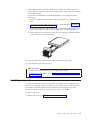
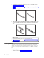
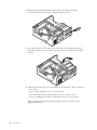
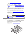
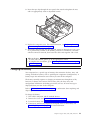
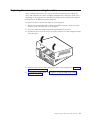
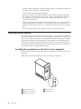
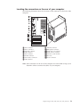
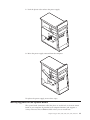
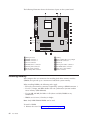
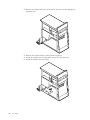
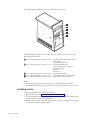
1
NetVista™
User Guide
Type 8301, 8302, 8303, 8304, 8305
Type 8306, 8307, 8308, 8309, 8310
Type 8311, 8312, 8313, 8314, 8315
NetVista™
User Guide
Type 8301, 8302, 8303, 8304, 8305
Type 8306, 8307, 8308, 8309, 8310
Type 8311, 8312, 8313, 8314, 8315
Note
Before using this information and the product it supports, be sure to read the “Safety Information” on page v and
Appendix E, “Notices” on page 97.
First Edition (April 2002)
© Copyright International Business Machines Corporation 2002. All rights reserved.
US Government Users Restricted Rights – Use, duplication or disclosure restricted by GSA ADP Schedule Contract
with IBM Corp.
Contents
Safety Information . . . . . . . . . . vi
Lithium battery notice . . . . . . . . . . . vi
Modem safety information . . . . . . . . . vi
Laser compliance statement. . . . . . . . . viii
Overview . . . . . . . . . . . . . . ix
Information resources . . . . . . . . . . . ix
Identifying your computer. . . . . . . . . . x
Chapter 1. Types 8301 and 8302 . . . . 1
Features . . . . . . . . . . . . . . . .
Specifications . . . . . . . . . . . . . .
Available options . . . . . . . . . . . . .
Handling static-sensitive devices. . . . . . . .
Installing external options . . . . . . . . . .
Locating connectors on the front of your computer
Locating the connectors on the rear of your
computer . . . . . . . . . . . . . .
1
4
5
5
6
6
8
Chapter 2. Types 8303, 8304, and 8312 . 9
Features . . . . . . . . . . . . . .
Specifications . . . . . . . . . . . .
Available options . . . . . . . . . .
Tools required . . . . . . . . . . .
Handling static-sensitive devices . . . . .
Installing external options . . . . . . .
Locating the connectors on the front of your
computer . . . . . . . . . . . .
Locating the connectors on the rear of your
computer . . . . . . . . . . . .
Obtaining device drivers . . . . . . .
Removing the cover . . . . . . . . .
Locating components . . . . . . . . .
Identifying parts on the system board . . .
Installing memory . . . . . . . . . .
Installing adapters . . . . . . . . . .
Installing internal drives . . . . . . . .
Drive specifications . . . . . . . . .
Installing a drive . . . . . . . . .
Installing a rope clip . . . . . . . . .
Changing the battery . . . . . . . . .
Erasing a lost or forgotten password (clearing
CMOS) . . . . . . . . . . . . . .
Replacing the cover and connecting the cables.
.
. 9
12
13
13
13
14
.
.
.
.
.
.
.
.
.
.
.
. 14
.
.
.
.
.
.
.
.
.
.
.
.
.
.
.
.
.
.
.
.
.
.
.
.
.
.
. 28
. 28
16
16
17
18
19
19
20
23
23
24
25
27
Chapter 3. Types 8305, 8306, 8309, and
8313 . . . . . . . . . . . . . . . . 31
Features . . . . . . . .
Specifications . . . . . . .
Available options . . . . .
Tools required . . . . . .
Handling static-sensitive devices
Installing external options . .
© Copyright IBM Corp. 2002
.
.
.
.
.
.
.
.
.
.
.
.
.
.
.
.
.
.
.
.
.
.
.
.
.
.
.
.
.
.
.
.
.
.
.
.
.
.
.
.
.
.
31
34
35
35
35
36
Locating the connectors on the front of your
computer . . . . . . . . . . . .
Locating the connectors on the rear of your
computer . . . . . . . . . . . .
Obtaining device drivers . . . . . . .
Removing the cover . . . . . . . . .
Locating components . . . . . . . . .
Identifying parts on the system board . . .
Installing memory . . . . . . . . . .
Installing adapters . . . . . . . . . .
Installing internal drives . . . . . . . .
Drive specifications . . . . . . . . .
Installing a drive . . . . . . . . .
Installing a rope clip . . . . . . . . .
Changing the battery . . . . . . . . .
Erasing a lost or forgotten password (clearing
CMOS) . . . . . . . . . . . . . .
Replacing the cover and connecting the cables.
.
. 36
.
.
.
.
.
.
.
.
.
.
.
.
.
.
.
.
.
.
.
.
.
.
.
.
.
.
. 50
. 51
38
38
39
40
41
41
42
44
45
45
48
49
Chapter 4. Types 8307, 8308, 8310,
8311, 8314, and 8315 . . . . . . . . . 53
Features . . . . . . . . . . . . .
Specifications . . . . . . . . . . . .
Available options . . . . . . . . . .
Tools required . . . . . . . . . . .
Handling static-sensitive devices . . . . .
Installing external options . . . . . . .
Locating the connectors on the front of your
computer . . . . . . . . . . . .
Locating the connectors on the rear of your
computer . . . . . . . . . . . .
Obtaining device drivers . . . . . . .
Removing the cover . . . . . . . . .
Locating components . . . . . . . . .
Moving the power supply . . . . . . .
Identifying parts on the system board . . .
Installing memory . . . . . . . . . .
Installing adapters . . . . . . . . . .
Installing internal drives . . . . . . . .
Drive specifications . . . . . . . . .
Installing a drive . . . . . . . . .
Installing a rope clip . . . . . . . . .
Changing the battery . . . . . . . . .
Erasing a lost or forgotten password (clearing
CMOS) . . . . . . . . . . . . . .
Replacing the cover and connecting the cables.
.
.
.
.
.
.
.
.
.
.
.
.
53
56
57
57
57
58
.
. 58
.
.
.
.
.
.
.
.
.
.
.
.
.
.
.
.
.
.
.
.
.
.
.
.
.
.
.
.
. 74
. 74
60
60
61
62
62
64
64
65
67
68
68
71
73
Chapter 5. Using the IBM Setup Utility
program . . . . . . . . . . . . . . 77
Starting the IBM Setup Utility program . .
Viewing and changing settings . . . . .
Exiting from the IBM Setup Utility program
Using passwords . . . . . . . . .
User password . . . . . . . . .
Administrator password . . . . . .
.
.
.
.
.
.
.
.
.
.
.
.
.
.
.
.
.
.
77
77
77
77
78
78
iii
Setting, changing, and deleting a password .
Using Security Profile by Device . . . . .
Selecting a startup device. . . . . . . .
Selecting a temporary startup device . . .
Changing the startup sequence . . . . .
.
.
.
.
.
.
.
.
.
.
78
78
79
79
79
Appendix A. Updating system
programs . . . . . . . . . . . . . 81
System programs . . . . . . . . . . .
Updating (flashing) BIOS from a diskette . .
Updating (flashing) BIOS from your operating
system . . . . . . . . . . . . . .
Recovering from a POST/BIOS update failure . .
. 81
. 81
. 81
. 82
Appendix B. Manual modem
commands . . . . . . . . . . . . . 83
Basic AT commands . . . . .
Extended AT commands . . . .
MNP/V.42/V.42bis/V.44 commands
Fax Class 1 commands . . . .
iv
User Guide
.
.
.
.
.
.
.
.
.
.
.
.
.
.
.
.
.
.
.
.
.
.
.
.
83
85
86
87
Fax Class 2 commands
Voice commands. . .
.
.
.
.
.
.
.
.
.
.
.
.
.
.
.
.
.
.
. 87
. 88
Appendix C. System address maps . . 91
System memory map .
I/O address map . .
DMA I/O address map
.
.
.
.
.
.
.
.
.
.
.
.
.
.
.
.
.
.
.
.
.
.
.
.
.
.
.
. 91
. 91
. 93
Appendix D. Interrupt request and
direct memory access channel
assignments . . . . . . . . . . . . 95
Appendix E. Notices . . . . . . . . . 97
Television output notice . . . . . . . . . . 97
Trademarks . . . . . . . . . . . . . . 98
PC Green label compliance information (Japan) . . 100
Index . . . . . . . . . . . . . . . 101
Safety Information
DANGER
Electrical current from power, telephone, and communication cables is
hazardous.
To avoid a shock hazard:
v Do not connect or disconnect any cables or perform installation, maintenance,
or reconfiguration of this product during an electrical storm.
v Connect all power cords to a properly wired and grounded electrical outlet.
v Connect to properly wired outlets any equipment that will be attached to this
product.
v When possible, use one hand only to connect or disconnect signal cables.
v Never turn on any equipment when there is evidence of fire, water, or
structural damage.
v Disconnect the attached power cords, telecommunications systems, networks,
and modems before you open the device covers, unless instructed otherwise
in the installation and configuration procedures.
v Connect and disconnect cables as described in the following table when
installing, moving, or opening covers on this product or attached devices.
To connect:
To disconnect:
1. Turn everything OFF.
1. Turn everything OFF.
2. First, attach all cables to devices.
2. First, remove power cords from outlet.
3. Attach signal cables to connectors.
3. Remove signal cables from connectors.
4. Attach power cords to outlet.
4. Remove all cables from devices.
5. Turn device ON.
DANGER
Le courant électrique provenant de l’alimentation, du téléphone et des câbles de
transmission peut présenter un danger.
Pour éviter tout risque de choc électrique :
v Ne manipulez aucun câble et n’effectuez aucune opération d’installation,
d’entretien ou de reconfiguration de ce produit au cours d’un orage.
v Branchez tous les cordons d’alimentation sur un socle de prise de courant
correctement câblé et mis à la terre.
v Branchez sur des socles de prise de courant correctement câblés tout
équipement connecté à ce produit.
v Lorsque cela est possible, n’utilisez qu’une seule main pour connecter ou
déconnecter les câbles d’interface.;
v Ne mettez jamais un équipement sous tension en cas d’incendie ou
d’inondation, ou en présence de dommages matériels.
v Avant de retirer les carters de l’unité, mettez celle-ci hors tension et
déconnectez ses cordons d’alimentation, ainsi que les câbles qui la relient aux
© Copyright IBM Corp. 2002
v
réseaux, aux systèmes de té lécommunication et aux modems (sauf instruction
contraire mentionnée dans les procédures d’installation et de configuration).
v Lorsque vous installez, que vous déplacez, ou que vous manipulez le présent
produit ou des périphériques qui lui sont raccordés, reportez-vous aux
instructions ci-dessous pour connecter et déconnecter les différents cordons.
Connexion:
Déconnexion:
1. Mettez les unités hors tension.
1. Mettez les unités hors tension.
2. Commencez par brancher tous les
cordons sur les unités.
2. Débranchez les cordons d’alimentation
des prises.
3. Branchez les câbles d’interface sur des
connecteurs.
3. Débranchez les câbles d’interface des
connecteurs.
4. Branchez les cordons d’alimentation sur 4. Débranchez tous les câbles des unités.
des prises.
5. Mettez les unités sous tension.
Lithium battery notice
CAUTION:
Danger of explosion if battery is incorrectly replaced.
When replacing the battery, use only IBM Part Number 33F8354 or an equivalent
type battery recommended by the manufacturer. The battery contains lithium
and can explode if not properly used, handled, or disposed of.
Do not:
v Throw or immerse into water
v Heat to more than 100°C (212°F)
v Repair or disassemble
Dispose of the battery as required by local ordinances or regulations.
ATTENTION
Danger d’explosion en cas de remplacement incorrect de la batterie.
Remplacer uniquement par une batterie IBM de type ou d’un type équivalent
recommandé par le fabricant. La batterie contient du lithium et peut exploser en
cas de mauvaise utilisation, de mauvaise manipulation ou de mise au rebut
inappropriée.
Ne pas :
v Lancer ou plonger dans l’eau
v Chauffer à plus de 100°C (212°F)
v Réparer ou désassembler
Mettre au rebut les batteries usagées conformément aux règlements locaux.
Modem safety information
To reduce the risk of fire, electrical shock, or injury when using telephone
equipment, always follow basic safety precautions, such as:
v Never install telephone wiring during a lightning storm.
vi
User Guide
v Never install telephone jacks in wet locations unless the jack is specifically
designed for wet locations.
v Never touch uninsulated telephone wires or terminals unless the telephone line
has been disconnected at the network interface.
v Use caution when installing or modifying telephone lines.
v Avoid using a telephone (other than a cordless type) during an electrical storm.
There may be a remote risk of electric shock from lightning.
v Do not use the telephone to report a gas leak in the vicinity of the leak.
Consignes de sécurité relatives au modem
Lors de l’utilisation de votre matériel téléphonique, il est important de respecter les
consignes ci-après afin de réduire les risques d’incendie, d’électrocution et d’autres
blessures :
v N’installez jamais de cordons téléphoniques durant un orage.
v Les prises téléphoniques ne doivent pas être installées dans des endroits
humides, excepté si le modèle a été conçu à cet effet.
v Ne touchez jamais un cordon téléphonique ou un terminal non isolé avant que
la ligne ait été déconnectée du réseau téléphonique.
v Soyez toujours prudent lorsque vous procédez à l’installation ou à la
modification de lignes téléphoniques.
v Si vous devez téléphoner pendant un orage, pour éviter tout risque de choc
électrique, utilisez toujours un téléphone sans fil.
v En cas de fuite de gaz, n’utilisez jamais un téléphone situé à proximité de la
fuite.
Laser compliance statement
Some IBM Personal Computer models are equipped from the factory with a
CD-ROM drive or a DVD-ROM drive. CD-ROM drives and DVD-ROM drives are
also sold separately as options. CD-ROM drives and DVD-ROM drives are laser
products. These drives are certified in the U.S. to conform to the requirements of
the Department of Health and Human Services 21 Code of Federal Regulations
(DHHS 21 CFR) Subchapter J for Class 1 laser products. Elsewhere, these drives
are certified to conform to the requirements of the International Electrotechnical
Commission (IEC) 825 and CENELEC EN 60 825 for Class 1 laser products.
When a CD-ROM drive or a DVD-ROM drive is installed, note the following
handling instructions.
CAUTION:
Use of controls or adjustments or performance of procedures other than those
specified herein might result in hazardous radiation exposure.
Removing the covers of the CD-ROM drive or DVD-ROM drive could result in
exposure to hazardous laser radiation. There are no serviceable parts inside the
CD-ROM drive or DVD-ROM drive. Do not remove the drive covers.
Some CD-ROM drives and DVD-ROM drives contain an embedded Class 3A or
Class 3B laser diode. Note the following statement.
Safety Information
vii
DANGER
Laser radiation when open. Do not stare into the beam, do not view directly with optical
instruments, and avoid direct exposure to the beam.
DANGER:
Certains modèles d’ordinateurs personnels sont équipés d’origine d’une unité de
CD-ROM ou de DVD-ROM. Mais ces unités sont également vendues séparément
en tant qu’options. L’unité de CD-ROM/DVD-ROM est un appareil à laser. Aux
État-Unis, l’unité de CD-ROM/DVD-ROM est certifiée conforme aux normes
indiquées dans le sous-chapitre J du DHHS 21 CFR relatif aux produits à laser de
classe 1. Dans les autres pays, elle est certifiée être un produit à laser de classe 1
conforme aux normes CEI 825 et CENELEC EN 60 825.
Lorsqu’une unité de CD-ROM/DVD-ROM est installée, tenez compte des
remarques suivantes:
ATTENTION: Pour éviter tout risque d’exposition au rayon laser, respectez les
consignes de réglage et d’utilisation des commandes, ainsi que les procédures
décrites.
L’ouverture de l’unité de CD-ROM/DVD-ROM peut entraîner un risque
d’exposition au rayon laser. Pour toute intervention, faites appel à du personnel
qualifié.
Certaines unités de CD-ROM/DVD-ROM peuvent contenir une diode à laser de
classe 3A ou 3B. Tenez compte de la consigne qui suit:
DANGER
Rayonnement laser lorsque le carter est ouvert. Évitez toute exposition directe des yeux
au rayon laser. Évitez de regarder fixement le faisceau ou de l’observer à l’aide
d’instruments optiques.
viii
User Guide
Overview
Thank you for selecting an IBM® computer. Your computer incorporates many of
the latest advances in computer technology and can be upgraded as your needs
change.
This publication supports several computer models. Information in this section will
help you identify your computer and help you find the chapter that contains
information specific to your computer.
Adding hardware options to your computer is an easy way to increase its
capabilities. Instructions for installing external and internal options are included in
this publication. When adding an option, use these instructions along with the
instructions that come along with the option.
Information resources
The Quick Reference that comes with your computer provides information for
installing your computer and starting the operating system. It also includes basic
troubleshooting information, software recovery procedures, help and service
information, and warranty information.
Access IBM, on your desktop, provides a link to more information about your
computer.
If you have Internet access, the most up-to-date manuals for your computer are
available from the World Wide Web. To access this information, point your browser
to
http://www.ibm.com/pc/support
Type your machine type and model number in the Quick Path field, and click Go.
© Copyright IBM Corp. 2002
ix
Identifying your computer
See Chapter 1, “Types 8301 and 8302”
on page 1.
See Chapter 2, “Types 8303, 8304, and
8312” on page 9.
See Chapter 3, “Types 8305, 8306,
8309, and 8313” on page 31.
See Chapter 4, “Types 8307, 8308,
8310, 8311, 8314, and 8315” on
page 53.
x
User Guide
Chapter 1. Types 8301 and 8302
This chapter provides an introduction to the features that are available for your
computer.
Important
Before you install or remove any option, read “Safety Information” on page v.
These precautions and guidelines will help you work safely.
Features
This section provides an overview of the computer features and preinstalled
software.
Microprocessor
Intel® Pentium® 4 processor with 512 KB of internal L2 cache memory and Intel
NetBurst™ micro-architecture
Memory
v Support for two dual inline memory modules (DIMMs)
v 512 KB flash memory for system programs
Internal drives
v Internal hard disk drive
Note: The hard disk drive should only be removed for maintenance or upgrade
and not for daily security.
v EIDE CD-ROM drive (some models)
Video subsystem
Intel Extreme™ graphics
Audio subsystem
Integrated SoundMAX 3 audio
Connectivity
10/100 Mbps integrated Intel Ethernet controller that supports the Wake on LAN®
feature
© Copyright IBM Corp. 2002
1
System management features
v Remote Program Load (RPL) and Dynamic Host Configuration Protocol (DHCP)
v Wake on LAN
v Wake on Ring (in the IBM Setup Utility program, this feature is called Serial Port
Ring Detect for an external modem and Modem Ring Detect for an internal
modem)
v Remote Administration
v Automatic power-on startup
v System Management (SM) BIOS and SM software
v Ability to store POST hardware test results
Input/output features
v 25-pin, Extended Capabilities Port (ECP)/Extended Parallel Port (EPP)
v Two 9-pin serial connectors
v Six 4-pin, USB connectors
v PS/2® mouse connector
v PS/2 keyboard connector
v Ethernet connector
v VGA monitor connector
v Three audio connectors (line in, line out, and microphone)
Expansion
Two drive bays
Power
v 125 W power supply with manual voltage selection switch
v Automatic 50/60 Hz input frequency switching
v Advanced Power Management support
v Advanced Configuration and Power Interface (ACPI) support
Security features
v User and administrator passwords
v Support for the addition of a rope clip and lockable cable
v Support for the addition of an integrated cable lock
v Startup sequence control
v Startup without keyboard or mouse
v Unattended start mode
v Serial and parallel port I/O control
v Security profile by device
IBM preinstalled software
Your computer might come with preinstalled software. If it does, an operating
system, device drivers to support built-in features, and other support programs are
included.
Operating systems (preinstalled) (varies by model type)
Note: Not all countries or regions will have these operating systems.
v Microsoft® Windows® XP Home
2
User Guide
v Microsoft Windows XP Professional
v Microsoft Windows 2000 Professional
Operating systems (tested for compatibility)1
v Microsoft Windows NT® Workstation Version 4.0
v Microsoft Windows 98 Second Edition
v OS/2®
1. The operating systems listed here are being tested for compatibility at the time this publication goes to press. Additional
operating systems might be identified by IBM as compatible with your computer following the publication of this booklet.
Corrections and additions to this list are subject to change. To determine if an operating system has been tested for compatibility,
check the Web site of the operating system vendor.
Chapter 1. Types 8301 and 8302
3
Specifications
This section lists the physical specifications for your computer.
Dimensions
Height: 110 mm (4.3 in.)
Heat output (approximate) in British thermal units (Btu)
per hour:
Width: 310 mm (12.2 in.)
Minimum configuration: 257 Btu/hr (75 watts)
Depth: 343 mm (13.5 in.)
Maximum configuration: 497 Btu/hr (145 watts)
Airflow
Weight
Minimum configuration as shipped: 8.1 kg (18 lb)
Maximum configuration: 9.1 kg (20 lb)
Environment
Air temperature:
System on: 10° to 35°C (50° to 95° F)
System off: 10° to 43°C (50° to 110° F)
Maximum altitude: 2134 m (7000 ft)
Note: The maximum altitude, 2134 m (7000 ft), is
the maximum altitude at which the specified air
temperatures apply. At higher altitudes, the
maximum air temperatures are lower than those
specified.
Humidity:
System on: 8% to 80%
System off: 8% to 80%
Electrical input
Input voltage:
Low range:
Minimum: 90 V ac
Maximum: 137 V ac
Input frequency range: 57–63 Hz
Voltage switch setting: 115 V ac
High range:
Approximately 0.40 cubic meters per minute (14 cubic
feet per minute) maximum
Acoustical noise-emission values
Average sound-pressure levels:
At operator position:
Idle: 34 dBA
Operating: 36 dBA
At bystander position - 1 meter (3.3 ft):
Idle: 31 dBA
Operating: 34 dBA
Declared (upper limit) sound-power levels:
Idle: 4.4 bels
Operating: 4.7 bels
Note: These levels were measured in controlled
acoustical environments according to the procedures
specified by the American National Standards
Institute (ANSI) S12.10 and ISO 7779 and are reported
in accordance with ISO 9296. Actual sound-pressure
levels in a given location might exceed the average
values stated because of room reflections and other
nearby noise sources. The declared sound-power
levels indicate an upper limit, below which a large
number of computers will operate.
Minimum: 180 V ac
Maximum: 265 V ac
Input frequency range: 47–53 Hz
Voltage switch setting: 230 V ac
Input kilovolt-amperes (kVA) (approximate):
Minimum configuration as shipped: 0.08 kVA
Maximum configuration: 0.30 kVA
Note: Power consumption and heat output vary
depending on the number and type of optional
features installed and the power-management
optional features in use.
4
User Guide
Note: See the Quick Reference for the classification of
your computer.
Available options
The following are some available options:
v External options
– Parallel port devices, such as printers and external drives
– Serial port devices, such as external modems and digital cameras
– Audio devices, such as external speakers for the sound system
– USB devices, such as printers, joysticks, and scanners
– Monitors
v Internal drives, such as
– CD-ROM drive (some models)
– Hard disk drive
For the latest information about available options, see the following World Wide
Web pages:
v http://www.ibm.com/pc/us/options/
v http://www.ibm.com/pc/support/
You can also obtain information by calling the following telephone numbers:
v Within the United States, call 1-800-IBM-2YOU (1-800-426-2968), your IBM
reseller, or IBM marketing representative.
v Within Canada, call 1-800-565-3344 or 1-800-IBM-4YOU.
v Outside the United States and Canada, contact your IBM reseller or IBM
marketing representative.
Handling static-sensitive devices
Static electricity, although harmless to you, can seriously damage computer
components and options.
When you add an option, do not open the static-protective package containing the
option until you are instructed to do so.
When you handle options and other computer components, take these precautions
to avoid static electricity damage:
v Limit your movement. Movement can cause static electricity to build up around
you.
v Always handle components carefully. Handle adapters and memory modules by
the edges. Never touch any exposed circuitry.
v Prevent others from touching components.
v When you install a new option, touch the static-protective package containing
the option to a metal expansion-slot cover or other unpainted metal surface on
the computer for at least two seconds. This reduces static electricity in the
package and your body.
v When possible, remove the option and install it directly in the computer without
setting the option down. When this is not possible, place the static-protective
package that the option came in on a smooth, level surface and place the option
on it.
v Do not place the option on the computer cover or other metal surface.
Chapter 1. Types 8301 and 8302
5
Installing external options
This section shows the various external connectors on your computer to which you
can attach external options, such as external speakers, a printer, or a scanner. For
some external options, you must install additional software in addition to making
the physical connection. When adding an external option, use the instructions that
come with the option to help you make the connection and install any software or
device drivers that are required for the option.
Locating connectors on the front of your computer
The following illustration shows the locations of the connectors on the front of the
computer.
1USB connector
2USB connector
6
User Guide
Locating the connectors on the rear of your computer
The following illustration shows the locations of the connectors on the rear of the
computer.
1Serial connector
2Mouse connector
3Parallel connector
4Ethernet connector
5Audio line in connector
6Power connector
7Audio line out connector
8 Microphone connector
9 USB connectors
10VGA monitor connector
11Serial connector
12USB connectors
13Keyboard connector
Note: Some connectors on the rear of the computer are color-coded to help you to
determine where to connect the cables on your computer.
Chapter 1. Types 8301 and 8302
7
8
User Guide
Connector
Description
Serial connector
Used to attach an external modem, serial printer, or other
devices that use a 9-pin serial connector.
Mouse connector
Used to attach a mouse, trackball, or other pointing device that
uses a standard mouse connector.
Parallel connector
Used to attach a parallel printer, parallel scanner, or other
devices that use a 25-pin parallel connector.
Ethernet connector
Used to attach an Ethernet cable for a local area network
(LAN).
Note: To operate the computer within FCC Class B limits, use
a Category 5 Ethernet cable.
Audio line in connector
Used to receive audio signals from an external audio device,
such as a stereo system. When you attach an external audio
device, a cable is connected between the audio line out
connector of the device and the audio line in connector of the
computer.
Audio line out connector
Used to send audio signals from the computer to external
devices, such as powered stereo speakers (speakers with
built-in amplifiers), headphones, multimedia keyboards, or the
audio line in connector on a stereo system or other external
recording device.
Microphone connector
Used to attach a microphone to your computer when you want
to record voice or other sounds on the hard disk if you use
speech-recognition software.
USB connectors
Used to attach a device that requires a Universal Serial Bus
(USB) connection, such as a USB scanner or USB printer. If you
have more than four USB devices, you can purchase a USB
hub, which you can use to connect additional USB devices.
Keyboard connector
Used to attach a keyboard that uses a standard keyboard
connector.
Chapter 2. Types 8303, 8304, and 8312
This chapter provides an introduction to the features and options that are available
for your computer. You can expand the capabilities of your computer by adding
memory, adapters, or drives. When installing an option, use these instructions
along with the instructions that come with the option.
Important
Before you install or remove any option, read “Safety Information” on page v.
These precautions and guidelines will help you work safely.
Features
This section provides an overview of the computer features and preinstalled
software.
Microprocessor (varies by model type)
Intel® Pentium® 4 processor with 256 KB or 512 KB of internal L2 cache memory
and Intel NetBurst™ micro-architecture
Memory
v Support for two dual inline memory modules (DIMMs)
v 512 KB flash memory for system programs
Internal drives
v 3.5-inch, 1.44 MB diskette drive
v Internal hard disk drive
v EIDE CD-ROM drive or DVD-ROM drive (some models)
Video subsystem
v Intel Extreme™ graphics
v Accelerated graphics port (AGP) video adapter slot on the system board (some
models)
Audio subsystem
Integrated SoundMAX 3 audio
© Copyright IBM Corp. 2002
9
Connectivity
v 10/100 Mbps integrated Intel Ethernet controller that supports the Wake on
LAN® feature
v Soft modem V.90/V.44 (some models)
System management features
v Remote Program Load (RPL) and Dynamic Host Configuration Protocol (DHCP)
v Wake on LAN
v Wake on Ring (in the IBM Setup Utility program, this feature is called Serial Port
Ring Detect for an external modem and Modem Ring Detect for an internal
modem)
v Remote Administration
v Automatic power-on startup
v System Management (SM) BIOS and SM software
v Ability to store POST hardware test results
Input/output features
v 25-pin, Extended Capabilities Port (ECP)/Extended Parallel Port (EPP)
v Two 9-pin serial connectors
v Six 4-pin, USB connectors
v PS/2® mouse connector
v PS/2 keyboard connector
v Ethernet connector
v VGA monitor connector
v Three audio connectors (line in, line out, and microphone)
v Front connectors for headphone, microphone, IEEE 1394, and S/PDIF (some
models)
Expansion
v Three drive bays
v Three 32-bit peripheral component interconnect (PCI) adapter slots (supports
low-profile adapters only)
v One accelerated graphics port (AGP) expansion slot (supports low-profile
adapters only)
Power
v
v
v
v
160 W power supply with manual voltage selection switch
Automatic 50/60 Hz input frequency switching
Advanced Power Management support
Advanced Configuration and Power Interface (ACPI) support
Security features
v User and administrator passwords
v Support for the addition of a rope clip and lockable cable
v Support for the addition of an integrated cable lock
v Startup sequence control
v Startup without diskette drive, keyboard, or mouse
v Unattended start mode
10
User Guide
v Diskette and hard disk I/O control
v Serial and parallel port I/O control
v Security profile by device
IBM preinstalled software
Your computer might come with preinstalled software. If it does, an operating
system, device drivers to support built-in features, and other support programs are
included.
Operating systems (preinstalled) (varies by model type)
Note: Not all countries or regions will have these operating systems.
v Microsoft® Windows® XP Home
v Microsoft Windows XP Professional
v Microsoft Windows 2000 Professional
Operating systems (tested for compatibility)2
v Microsoft Windows NT® Workstation Version 4.0
v Microsoft Windows 98 Second Edition
v OS/2®
2. The operating systems listed here are being tested for compatibility at the time this publication goes to press. Additional
operating systems might be identified by IBM as compatible with your computer following the publication of this booklet.
Corrections and additions to this list are subject to change. To determine if an operating system has been tested for compatibility,
check the Web site of the operating system vendor.
Chapter 2. Types 8303, 8304, and 8312
11
Specifications
This section lists the physical specifications for your computer.
Dimensions
Height: 104 mm (4.1 in.)
Heat output (approximate) in British thermal units (Btu)
per hour:
Width: 360 mm (14.2 in.)
Minimum configuration: 257 Btu/hr (75 watts)
Depth: 412 mm (16.2 in.)
Maximum configuration: 806 Btu/hr (235 watts)
Airflow
Weight
Minimum configuration as shipped: 8.1 kg (18 lb)
Maximum configuration: 9.1 kg (20 lb)
Environment
Air temperature:
System on: 10° to 35°C (50° to 95° F)
System off: 10° to 43°C (50° to 110° F)
Maximum altitude: 2134 m (7000 ft)
Note: The maximum altitude, 2134 m (7000 ft), is
the maximum altitude at which the specified air
temperatures apply. At higher altitudes, the
maximum air temperatures are lower than those
specified.
Humidity:
System on: 8% to 80%
System off: 8% to 80%
Electrical input
Input voltage:
Low range:
Minimum: 90 V ac
Maximum: 137 V ac
Input frequency range: 57–63 Hz
Voltage switch setting: 115 V ac
High range:
Approximately 0.45 cubic meters per minute (16 cubic
feet per minute) maximum
Acoustical noise-emission values
Average sound-pressure levels:
At operator position:
Idle: 32 dBA
Operating: 35 dBA
At bystander position - 1 meter (3.3 ft):
Idle: 29 dBA
Operating: 33 dBA
Declared (upper limit) sound-power levels:
Idle: 4.4 bels
Operating: 4.7 bels
Note: These levels were measured in controlled
acoustical environments according to the procedures
specified by the American National Standards
Institute (ANSI) S12.10 and ISO 7779 and are reported
in accordance with ISO 9296. Actual sound-pressure
levels in a given location might exceed the average
values stated because of room reflections and other
nearby noise sources. The declared sound-power
levels indicate an upper limit, below which a large
number of computers will operate.
Minimum: 180 V ac
Maximum: 265 V ac
Input frequency range: 47–53 Hz
Voltage switch setting: 230 V ac
Input kilovolt-amperes (kVA) (approximate):
Minimum configuration as shipped: 0.08 kVA
Maximum configuration: 0.30 kVA
Note: Power consumption and heat output vary
depending on the number and type of optional
features installed and the power-management
optional features in use.
12
User Guide
Note: See the Quick Reference for the classification of
your computer.
Available options
The following are some available options:
v External options
– Parallel port devices, such as printers and external drives
– Serial port devices, such as external modems and digital cameras
– Audio devices, such as external speakers for the sound system
– USB devices, such as printers, joysticks, and scanners
– Security device, such as a rope clip
– Monitors
– IEEE 1394 devices (requires an IEEE 1394 adapter)
v Internal options
– System memory, called dual inline memory modules (DIMMs)
– Peripheral component interconnect (PCI) adapters (supports low-profile
adapters only)
– Accelerated graphics port (AGP) adapters (supports low-profile adapters
only)
– Internal drives, such as:
- CD-ROM drive and DVD-ROM drive (some models)
- Hard disk drive
- Diskette drives and other removable media drives
For the latest information about available options, see the following World Wide
Web pages:
v http://www.ibm.com/pc/us/options/
v http://www.ibm.com/pc/support/
You can also obtain information by calling the following telephone numbers:
v Within the United States, call 1-800-IBM-2YOU (1-800-426-2968), your IBM
reseller, or IBM marketing representative.
v Within Canada, call 1-800-565-3344 or 1-800-IBM-4YOU.
v Outside the United States and Canada, contact your IBM reseller or IBM
marketing representative.
Tools required
To install some options in your computer, you might need a flat-blade or Phillips
screwdriver. Additional tools might be needed for certain options. See the
instructions that come with the option.
Handling static-sensitive devices
Static electricity, although harmless to you, can seriously damage computer
components and options.
When you add an option, do not open the static-protective package containing the
option until you are instructed to do so.
When you handle options and other computer components, take these precautions
to avoid static electricity damage:
Chapter 2. Types 8303, 8304, and 8312
13
v Limit your movement. Movement can cause static electricity to build up around
you.
v Always handle components carefully. Handle adapters and memory modules by
the edges. Never touch any exposed circuitry.
v Prevent others from touching components.
v When you install a new option, touch the static-protective package containing
the option to a metal expansion-slot cover or other unpainted metal surface on
the computer for at least two seconds. This reduces static electricity in the
package and your body.
v When possible, remove the option and install it directly in the computer without
setting the option down. When this is not possible, place the static-protective
package that the option came in on a smooth, level surface and place the option
on it.
v Do not place the option on the computer cover or other metal surface.
Installing external options
This section shows the various external connectors on your computer to which you
can attach external options, such as external speakers, a printer, or a scanner. For
some external options, you must install additional software in addition to making
the physical connection. When adding an external option, use the information in
this section to identify the required connector, and then use the instructions that
come with the option to help you make the connection and install any software or
device drivers that are required for the option.
Locating the connectors on the front of your computer
The following illustration shows the locations of the connectors on the front of the
computer.
1USB connector
2USB connector
14
User Guide
Locating the connectors on the rear of your computer
The following illustration shows the locations of the connectors on the rear of the
computer.
1Serial connector
2Mouse connector
3Parallel connector
4Ethernet connector
5Audio line in connector
6Power connector
7PCI slots
8AGP slot (some models)
9 Audio line out connector
10Microphone connector
11USB connectors
12VGA monitor connector
13Serial connector
14USB connectors
15Keyboard connector
Note: Some connectors on the rear of the computer are color-coded to help you to
determine where to connect the cables on your computer.
Chapter 2. Types 8303, 8304, and 8312
15
Connector
Description
Serial connector
Used to attach an external modem, serial printer, or other
devices that use a 9-pin serial connector.
Mouse connector
Used to attach a mouse, trackball, or other pointing device that
uses a standard mouse connector.
Parallel connector
Used to attach a parallel printer, parallel scanner, or other
devices that use a 25-pin parallel connector.
Ethernet connector
Used to attach an Ethernet cable for a local area network
(LAN).
Note: To operate the computer within FCC Class B limits, use
a Category 5 Ethernet cable.
Audio line in connector
Used to receive audio signals from an external audio device,
such as a stereo system. When you attach an external audio
device, a cable is connected between the audio line out
connector of the device and the audio line in connector of the
computer.
Audio line out connector
Used to send audio signals from the computer to external
devices, such as powered stereo speakers (speakers with
built-in amplifiers), headphones, multimedia keyboards, or the
audio line in connector on a stereo system or other external
recording device.
Microphone connector
Used to attach a microphone to your computer when you want
to record voice or other sounds on the hard disk if you use
speech-recognition software.
USB connectors
Used to attach a device that requires a Universal Serial Bus
(USB) connection, such as a USB scanner or USB printer. If you
have more than four USB devices, you can purchase a USB
hub, which you can use to connect additional USB devices.
Keyboard connector
Used to attach a keyboard that uses a standard keyboard
connector.
Obtaining device drivers
You can obtain device drivers for operating systems that are not preinstalled at
http://www.ibm.com/pc/support/ on the World Wide Web. Installation
instructions are provided in README files with the device-driver files.
16
User Guide
Removing the cover
Important
Read “Safety Information” on page v and “Handling static-sensitive devices”
on page 13 before removing the cover.
To remove the cover:
1. Shut down your operating system, remove any media (diskettes, CDs, or tapes)
from the drives, and turn off all attached devices and the computer.
2. Unplug all power cords from electrical outlets.
3. Disconnect all cables attached to the computer. This includes power cords,
input/output (I/O) cables, and any other cables that are connected to the
computer.
4. Press the buttons on the sides of the computer and pivot the rear end of the
cover up toward the front of the computer.
Chapter 2. Types 8303, 8304, and 8312
17
Locating components
The following illustration will help you locate the various components in your
computer.
1Power supply
2PCI slot
3AGP slot (some models)
4Support bar
5DIMM
6Hard disk drive
7CD-ROM drive or DVD-ROM drive
8Diskette drive
Identifying parts on the system board
The system board (sometimes called the planar or motherboard) is the main circuit
board in your computer. It provides basic computer functions and supports a
variety of devices that are IBM-installed or that you can install later.
18
User Guide
The following illustration shows the locations of parts on the system board.
1
2
3
4
5
6
7
8
Microprocessor
DIMM connector 1
DIMM connector 2
Power connector
Diskette drive connector
Primary IDE connector
Front panel connector
Secondary IDE connector
9 Battery
10Clear CMOS/Recovery jumper
11SCSI LED connector
12PCI slots
13Front panel audio connector
14CD-ROM audio connector
15AGP slot (some models)
16Serial connector
Installing memory
Your computer has two connectors for installing dual inline memory modules
(DIMMs) that provide up to a maximum of 2.0 GB of system memory.
When installing DIMMs, the following rules apply:
v Fill each system memory connector sequentially, starting at DIMM connector 1.
v Use 2.5 V, 184-pin, 266 MHz double data rate synchronous dynamic random
access memory (DDR SDRAM).
v Use 128 MB, 256 MB, 512 MB or 1.0 GB (when available) DIMMs in any
combination.
v DIMMs are 38.1 mm (1.5 inches) in height.
Note: Only DDR SDRAM DIMMs can be used.
To install a DIMM:
1. Remove the cover. See “Removing the cover” on page 17.
Chapter 2. Types 8303, 8304, and 8312
19
2. To locate the DIMM connectors. See “Identifying parts on the system board” on
page 18.
3. Open the retaining clips.
4. Make sure the notches in the DIMM align with the tabs on the connector. Push
or insert the DIMM straight down into the connector until the retaining clips
close.
What to do next:
v To work with another option, go to the appropriate section.
v To complete the installation, go to “Replacing the cover and connecting the
cables” on page 28.
Installing adapters
This section provides information and instructions for installing and removing
adapters. Your computer has three expansion slots for PCI adapters and one slot
used for an AGP adapter. Adapters must be low profile. Your computer supports
adapters up to 168 mm (6.6 inches) long.
To install an adapter:
1. Remove the cover. See “Removing the cover” on page 17.
20
User Guide
2. Pivot one of the drive bay latch handles toward the front of the computer and
then pivot the drive bay cage upward, as shown, until it is latched in the up
position. Repeat this procedure for the remaining drive bay.
3. Remove the support bar by pulling it outward from the computer.
Chapter 2. Types 8303, 8304, and 8312
21
4. Remove the adapter-slot-cover latch and the slot cover for the appropriate
expansion slot.
5. Remove the adapter from its static-protective package.
6. Install the adapter into the appropriate slot on the system board.
7. Install the adapter-slot-cover latch.
8. Clear any cables that might impede the replacement of the drive bays.
9. Replace the support bar and pivot the two drive bays back to their original
positions.
What to do next:
v To work with another option, go to the appropriate section.
v To complete the installation, go to “Replacing the cover and connecting the
cables” on page 28.
22
User Guide
Installing internal drives
This section provides information and instructions for installing and removing
internal drives.
Internal drives are devices that your computer uses to read and store data. You can
add or replace drives to your computer to increase storage capacity and to enable
your computer to read other types of media such as CD-ROM.
Internal drives are installed in bays. In this book, the bays are referred to as bay 1,
bay 2, and so on.
When you install an internal drive, it is important to note what type and size of
drive that you can install in each bay. Also, it is important to correctly connect the
internal drive cables to the installed drive.
Drive specifications
Your computer might come with the following IBM-installed drives:
v A 3.5-inch diskette drive in bay 1
v A CD-ROM drive or DVD-ROM drive in bay 2 (some models)
v A 3.5-inch hard disk drive in bay 3
Any bay that does not have a drive installed has a static shield and bay panel
installed.
The following illustration shows the locations of the drive bays.
The following list describes some of the drives that you can install in each bay and
their height requirements:
1Bay 1 - Maximum height: 25.8 mm (1.0 in.) 3.5-inch diskette drive (preinstalled)
2Bay 2 - Maximum height: 43.0 mm (1.7 in.) CD-ROM drive or DVD-ROM drive
(preinstalled in some models)
3Bay 3 - Maximum height: 25.8 mm (1.0 in.) 3.5-inch hard disk drive (preinstalled)
Notes:
1. Drives that are greater than 43.0 mm (1.7 in.) high cannot be installed.
2. Install removable media (tape or CD) drives in the accessible bay (bay 2).
Chapter 2. Types 8303, 8304, and 8312
23
Installing a drive
To install a CD-ROM drive or DVD-ROM drive in bay 2, follow these steps:
1. Remove the cover (see “Removing the cover” on page 17).
2. If the drive you are installing is a removable-media drive, remove the bay
panel from the front bezel.
3. Remove the metal shield from the drive bay by inserting a flat-blade
screwdriver into one of the slots and gently prying it loose.
4. Make sure the drive is set correctly as the master device. Refer to the
documentation that comes with your CD-ROM drive or DVD-ROM drive for
master/slave jumper information.
5. Pivot the drive bay latch handle toward the front of the computer and then
pivot the drive bay cage upward, as shown, until it is latched in the up
position.
6. Install the drive into the bay. Align the screw holes and insert the two screws.
24
User Guide
7. Each integrated drive electronics (IDE) drive requires two cables; a four-wire
power cable that connects to the power supply, and a signal cable that connects
to the system board.
To connect a CD-ROM drive or DVD-ROM drive to your computer, follow
these steps:
a. Locate the signal cable that comes with your computer or with the new
drive.
b. Locate the secondary IDE connector on the system board. See “Identifying
parts on the system board” on page 18.
c. Connect one end of the signal cable to the secondary IDE connector on the
system board and the other to the CD-ROM drive or DVD-ROM drive.
d. Your computer has extra power connectors for connecting additional drives.
Connect the power cable to the drive.
8. Clear any cables that might impede replacement of the drive cage.
9. Pivot the drive cage back into place.
What to do next:
v To work with another option, go to the appropriate section.
v To complete the installation, go to “Replacing the cover and connecting the
cables” on page 28.
Installing a rope clip
To help prevent hardware theft, you can add a 3/16-inch or 5-mm rope clip and
cable to your computer. After you add the security cable, make sure that it does
not interfere with other cables that are connected to the computer. For more
information about security, see Installing a cable lock in Access IBM.
To install a rope clip:
1. Remove the cover (see “Removing the cover” on page 17).
Chapter 2. Types 8303, 8304, and 8312
25
2. Use a tool, such as a screwdriver, to remove the two metal knockouts.
3. Press both sides of the air baffle and lift it outward from the computer to
remove.
4. Insert the rope clip through the rear panel; then attach and tighten the nuts
with an appropriately sized or adjustable wrench.
5. Replace the computer cover. For more information, see “Replacing the cover
and connecting the cables” on page 28.
6. Thread the cable through the rope clip and around an object that is not a part
of or permanently secured to the building structure or foundation, and from
which it cannot be removed; then fasten the cable ends together with a lock.
What to do next:
v To work with another option, go to the appropriate section.
v To complete the installation, go to “Replacing the cover and connecting the
cables” on page 28.
26
User Guide
Changing the battery
Your computer has a special type of memory that maintains the date, time, and
settings for built-in features, such as parallel-port assignments (configuration). A
battery keeps this information active when you turn off the computer.
The battery normally requires no charging or maintenance throughout its life;
however, no battery lasts forever. If the battery fails, the date, time, and
configuration information (including passwords) are lost. An error message is
displayed when you turn on the computer.
Refer to “Lithium battery notice” on page vi for information about replacing and
disposing of the battery.
To change the battery:
1. Turn off the computer and all attached devices.
2. Remove the cover. See “Removing the cover” on page 17.
3. Locate the battery. See “Identifying parts on the system board” on page 18.
4. If necessary, remove any adapters that impede access to the battery. See
“Installing adapters” on page 20 for more information.
5. Remove the old battery.
6. Install the new battery.
7. Replace any adapters that were removed to gain access to the battery. See
“Installing adapters” on page 20 for instructions for replacing adapters.
8. Replace the cover, and plug in the power cord. See “Replacing the cover and
connecting the cables” on page 28.
Note: When the computer is turned on for the first time after battery
replacement, an error message might be displayed. This is normal after
replacing the battery.
9. Turn on the computer and all attached devices.
10. Use the IBM Setup Utility program to set the date and time and any
passwords. See Chapter 5, “Using the IBM Setup Utility program” on page 77.
Chapter 2. Types 8303, 8304, and 8312
27
Erasing a lost or forgotten password (clearing CMOS)
This section applies to lost or forgotten passwords. For more information about
lost or forgotten passwords, see Access IBM on your desktop.
To erase a forgotten password:
1. Turn off the computer and all attached devices.
2. Remove the cover. See “Removing the cover” on page 17.
3. Locate the Clear CMOS/Recovery jumper on the system board. See
“Identifying parts on the system board” on page 18.
4. If necessary, see “Installing adapters” on page 20 to remove any adapters that
impede access to the Clear CMOS/Recovery jumper.
5. Move the jumper from the standard position (pins 1 and 2) to the
maintenance or configure position (pins 2 and 3).
6. Replace the cover and connect the power cord. See “Replacing the cover and
connecting the cables”.
7. Restart the computer, leave it on for approximately 10 seconds. Turn off the
computer by holding the power switch for approximately 5 seconds. The
computer will turn off.
8. Repeat steps 2 through 4 on page 28.
9. Move the jumper back to the standard (pins 1 and 2).
10. Replace the cover and connect the power cord. See “Replacing the cover and
connecting the cables”.
Replacing the cover and connecting the cables
After working with options, you need to install any removed parts, replace the
cover, and reconnect cables, including telephone lines and power cords. Also,
depending on the option that is installed, you might need to confirm the updated
information in the IBM Setup Utility program.
To replace the cover and connect cables to your computer:
1. Ensure that all components have been reassembled correctly and that no tools
or loose screws are left inside your computer.
2. Clear any cables that might impede the replacement of the cover.
28
User Guide
3. Position the cover over the chassis and pivot it down over the computer until it
snaps into place.
4. Reconnect the external cables and power cords to the computer. See “Installing
external options” on page 14.
5. To update the configuration, see Chapter 5, “Using the IBM Setup Utility
program” on page 77.
Chapter 2. Types 8303, 8304, and 8312
29
30
User Guide
Chapter 3. Types 8305, 8306, 8309, and 8313
This chapter provides an introduction to the features and options that are available
for your computer. You can expand the capabilities of your computer by adding
memory, adapters, or drives. When installing an option, use these instructions
along with the instructions that come with the option.
Important
Before you install or remove any option, read “Safety Information” on page v.
These precautions and guidelines will help you work safely.
Features
This section provides an overview of the computer features and preinstalled
software.
Microprocessor (varies by model type)
Intel® Pentium® 4 processor with 256 KB or 512 KB of internal L2 cache memory
and Intel NetBurst™ micro-architecture
Memory
v Support for two dual inline memory modules (DIMMs)
v 512 KB flash memory for system programs
Internal drives
v 3.5-inch, 1.44 MB diskette drive
v Internal hard disk drive
v EIDE CD drive or DVD drive (some models)
Video subsystem
v Intel Extreme™ graphics
v Accelerated graphics port (AGP) video adapter slot on the system board (some
models)
Audio subsystem
Integrated SoundMAX 3 audio
© Copyright IBM Corp. 2002
31
Connectivity
10/100 Mbps integrated Intel Ethernet controller that supports the Wake on LAN®
feature
System management features
v Remote Program Load (RPL) and Dynamic Host Configuration Protocol (DHCP)
v Wake on LAN
v Wake on Ring (in the IBM Setup Utility program, this feature is called Serial Port
Ring Detect for an external modem and Modem Ring Detect for an internal
modem)
v Remote Administration
v Automatic power-on startup
v System Management (SM) BIOS and SM software
v Ability to store POST hardware test results
Input/output features
v 25-pin, Extended Capabilities Port (ECP)/Extended Parallel Port (EPP)
v Two 9-pin serial connectors
v Six 4-pin, USB connectors
v PS/2® mouse connector
v PS/2 keyboard connector
v Ethernet connector
v VGA monitor connector
v Three audio connectors (line in, line out, and microphone)
Expansion
v Four drive bays
v Three 32-bit peripheral component interconnect (PCI) adapter slots
v One accelerated graphics port (AGP) expansion slot
Power
v 185 W power supply with manual voltage selection switch
v Automatic 50/60 Hz input frequency switching
v Advanced Power Management support
v Advanced Configuration and Power Interface (ACPI) support
Security features
v User and administrator passwords
v Support for the addition of a rope clip and lockable cable
v Support for the addition of an integrated cable lock
v Startup sequence control
v Startup without diskette drive, keyboard, or mouse
v Unattended start mode
v Diskette and hard disk I/O control
v Serial and parallel port I/O control
v Security profile by device
32
User Guide
IBM preinstalled software
Your computer might come with preinstalled software. If it does, an operating
system, device drivers to support built-in features, and other support programs are
included.
Operating systems (preinstalled) (varies by model type)
Note: Not all countries or regions will have these operating systems.
v Microsoft® Windows® XP Home
v Microsoft Windows XP Professional
v Microsoft Windows 2000 Professional
Operating systems (tested for compatibility)3
v Microsoft Windows NT® Workstation Version 4.0
v Microsoft Windows 98 Second Edition
v OS/2®
3. The operating systems listed here are being tested for compatibility at the time this publication goes to press. Additional
operating systems might be identified by IBM as compatible with your computer following the publication of this booklet.
Corrections and additions to this list are subject to change. To determine if an operating system has been tested for compatibility,
check the Web site of the operating system vendor.
Chapter 3. Types 8305, 8306, 8309, and 8313
33
Specifications
This section lists the physical specifications for your computer.
Dimensions
Height: 140 mm (5.5 in.)
Heat output (approximate) in British thermal units (Btu)
per hour:
Width: 425 mm (16.7 in.)
Minimum configuration: 257 Btu/hr (75 watts)
Depth: 414 mm (16.3 in)
Maximum configuration: 890 Btu/hr (260 watts)
Airflow
Weight
Minimum configuration as shipped: 10.0 kg (22 lb)
Maximum configuration: 11.4 kg (25.0 lb)
Environment
Air temperature:
System on: 10° to 35°C (50° to 95° F)
System off: 10° to 43°C (50° to 110° F)
Maximum altitude: 2134 m (7000 ft)
Note: The maximum altitude, 2134 m (7000 ft), is
the maximum altitude at which the specified air
temperatures apply. At higher altitudes, the
maximum air temperatures are lower than those
specified.
Humidity:
System on: 8% to 80%
System off: 8% to 80%
Electrical input
Input voltage:
Low range:
Minimum: 90 V ac
Maximum: 137 V ac
Input frequency range: 57–63 Hz
Voltage switch setting: 115 V ac
High range:
Approximately 0.56 cubic meters per minute (20 cubic
feet per minute) maximum
Acoustical noise-emission values
Average sound-pressure levels:
At operator position:
Idle: 33 dBA
Operating: 36 dBA
At bystander position - 1 meter (3.3 ft):
Idle: 30 dBA
Operating: 33 dBA
Declared (upper limit) sound-power levels:
Idle: 4.4 bels
Operating: 4.7 bels
Note: These levels were measured in controlled
acoustical environments according to the procedures
specified by the American National Standards
Institute (ANSI) S12.10 and ISO 7779 and are reported
in accordance with ISO 9296. Actual sound-pressure
levels in a given location might exceed the average
values stated because of room reflections and other
nearby noise sources. The declared sound-power
levels indicate an upper limit, below which a large
number of computers will operate.
Minimum: 180 V ac
Maximum: 265 V ac
Input frequency range: 47–53 Hz
Voltage switch setting: 230 V ac
Input kilovolt-amperes (kVA) (approximate):
Minimum configuration as shipped: 0.08 kVA
Maximum configuration: 0.3 kVA
Note: Power consumption and heat output vary
depending on the number and type of optional
features installed and the power-management
optional features in use.
34
User Guide
Note: See the Quick Reference for the classification of
your computer.
Available options
The following are some available options:
v External options
– Parallel port devices, such as printers and external drives
– Serial port devices, such as external modems and digital cameras
– Audio devices, such as external speakers for the sound system
– USB devices, such as printers, joysticks, and scanners
– Security device, such as a rope clip
– Monitors
v Internal options
– System memory, called dual inline memory modules (DIMMs)
– Peripheral component interconnect (PCI) adapters
– Accelerated graphics port (AGP) adapters
– Internal drives, such as:
- CD drive or DVD drive (some models)
- Hard disk drive
- Diskette drives and other removable media drives
For the latest information about available options, see the following World Wide
Web pages:
v http://www.ibm.com/pc/us/options/
v http://www.ibm.com/pc/support/
You can also obtain information by calling the following telephone numbers:
v Within the United States, call 1-800-IBM-2YOU (1-800-426-2968), your IBM
reseller, or IBM marketing representative.
v Within Canada, call 1-800-565-3344 or 1-800-IBM-4YOU.
v Outside the United States and Canada, contact your IBM reseller or IBM
marketing representative.
Tools required
To install some options in your computer, you might need a flat-blade or Phillips
screwdriver. Additional tools might be needed for certain options. See the
instructions that come with the option.
Handling static-sensitive devices
Static electricity, although harmless to you, can seriously damage computer
components and options.
When you add an option, do not open the static-protective package containing the
option until you are instructed to do so.
When you handle options and other computer components, take these precautions
to avoid static electricity damage:
v Limit your movement. Movement can cause static electricity to build up around
you.
v Always handle components carefully. Handle adapters and memory modules by
the edges. Never touch any exposed circuitry.
Chapter 3. Types 8305, 8306, 8309, and 8313
35
v Prevent others from touching components.
v When you install a new option, touch the static-protective package containing
the option to a metal expansion-slot cover or other unpainted metal surface on
the computer for at least two seconds. This reduces static electricity in the
package and your body.
v When possible, remove the option and install it directly in the computer without
setting the option down. When this is not possible, place the static-protective
package that the option came in on a smooth, level surface and place the option
on it.
v Do not place the option on the computer cover or other metal surface.
Installing external options
This section shows the various external connectors on your computer to which you
can attach external options, such as external speakers, a printer, or a scanner. For
some external options, you must install additional software in addition to making
the physical connection. When adding an external option, use the information in
this section to identify the required connector, and then use the instructions that
come with the option to help you make the connection and install any software or
device drivers that are required for the option.
Locating the connectors on the front of your computer
The following illustration shows the locations of the connectors on the front of the
computer.
1USB connector
2USB connector
36
User Guide
Locating the connectors on the rear of your computer
The following illustration shows the locations of the connectors on the rear of the
computer.
1Power connector
2Mouse connector
3Serial connector
4Parallel connector
5Ethernet connector
6Audio line in connector
7PCI slots
8AGP slot (some models)
9 Audio line out connector
10Microphone connector
11USB connectors
12VGA monitor connector
13Serial connector
14USB connectors
15Keyboard connector
Note: Some connectors on the rear of the computer are color-coded to help you to
determine where to connect the cables on your computer.
Chapter 3. Types 8305, 8306, 8309, and 8313
37
Connector
Description
Mouse connector
Used to attach a mouse, trackball, or other pointing device that
uses a standard mouse connector.
Serial connector
Used to attach an external modem, serial printer, or other
devices that use a 9-pin serial connector.
Parallel connector
Used to attach a parallel printer, parallel scanner, or other
devices that use a 25-pin parallel connector.
Ethernet connector
Used to attach an Ethernet cable for a local area network
(LAN).
Note: To operate the computer within FCC Class B limits, use
a Category 5 Ethernet cable.
Audio line in connector
Used to receive audio signals from an external audio device,
such as a stereo system. When you attach an external audio
device, a cable is connected between the audio line out
connector of the device and the audio line in connector of the
computer.
Audio line out connector
Used to send audio signals from the computer to external
devices, such as powered stereo speakers (speakers with
built-in amplifiers), headphones, multimedia keyboards, or the
audio line in connector on a stereo system or other external
recording device.
Microphone connector
Used to attach a microphone to your computer when you want
to record voice or other sounds on the hard disk if you use
speech-recognition software.
USB connectors
Used to attach a device that requires a Universal Serial Bus
(USB) connection, such as a USB scanner or USB printer. If you
have more than four USB devices, you can purchase a USB
hub, which you can use to connect additional USB devices.
Keyboard connector
Used to attach a keyboard that uses a standard keyboard
connector.
Obtaining device drivers
You can obtain device drivers for operating systems that are not preinstalled at
http://www.ibm.com/pc/support/ on the World Wide Web. Installation
instructions are provided in README files with the device-driver files.
38
User Guide
Removing the cover
Important:
Read “Safety Information” on page v and “Handling static-sensitive devices”
on page 35 before removing the cover.
To remove the cover:
1. Shut down your operating system, remove any media (diskettes, CDs, or tapes)
from the drives, and turn off all attached devices and the computer.
2. Unplug all power cords from electrical outlets.
3. Disconnect all cables attached to the computer. This includes power cords,
input/output (I/O) cables, and any other cables that are connected to the
computer.
4. Press the buttons on the sides of the computer and pivot the rear end of the
cover up toward the front of the computer.
Chapter 3. Types 8305, 8306, 8309, and 8313
39
Locating components
The following illustration will help you locate the various components in your
computer.
1CD drive or DVD drive
2USB connector
3USB connector
4Optional drive bay
5Hard disk drive
6Diskette drive
7 Battery
8 DIMMs
9 Microprocessor and heat sink
10AGP slot (some models)
11PCI slots
Identifying parts on the system board
The system board (sometimes called the planar or motherboard) is the main circuit
board in your computer. It provides basic computer functions and supports a
variety of devices that are IBM-installed or that you can install later.
40
User Guide
The following illustration shows the locations of parts on the system board.
1
2
3
4
5
6
7
8
Microprocessor
DIMM connector 1
DIMM connector 2
Power connector
Diskette drive connector
Primary IDE connector
Front panel connector
Secondary IDE connector
9 Battery
10Clear CMOS/Recovery jumper
11SCSI LED connector
12PCI slots
13Front panel audio connector
14CD-ROM audio connector
15AGP slot (some models)
16Serial connector
Installing memory
Your computer has two connectors for installing dual inline memory modules
(DIMMs) that provide up to a maximum of 2.0 GB of system memory.
When installing DIMMs, the following rules apply:
v Fill each system memory connector sequentially, starting at DIMM connector 1.
v Use 2.5 V, 184-pin, 266 MHz double data rate synchronous dynamic random
access memory (DDR SDRAM).
v Use 128 MB, 256 MB, 512 MB or 1.0 GB (when available) DIMMs in any
combination.
v DIMMs are 38.1 mm (1.5 inches) in height.
Note: Only DDR SDRAM DIMMs can be used.
To install a DIMM:
1. Remove the cover. See “Removing the cover” on page 39.
Chapter 3. Types 8305, 8306, 8309, and 8313
41
2. You might have to remove an adapter to gain access to the DIMM slots. See
“Installing adapters” on page 42.
3. To locate the DIMM connectors. See “Identifying parts on the system board” on
page 40.
4. Open the retaining clips.
5. Make sure the notches in the DIMM align with the tabs on the connector. Push
or insert the DIMM straight down into the connector until the retaining clips
close.
What to do next:
v To work with another option, go to the appropriate section.
v To complete the installation, go to “Replacing the cover and connecting the
cables” on page 51.
Installing adapters
This section provides information and instructions for installing and removing
adapters. Your computer has three expansion slots for PCI adapters and one slot
used for an AGP adapter. You can install an adapter up to 340 mm (13.4 inches)
long.
To install an adapter:
1. Remove the cover. See “Removing the cover” on page 39.
42
User Guide
2. Remove the adapter-slot-cover latch and the slot cover for the appropriate
expansion slot.
3. Remove the adapter from its static-protective package.
4. Install the adapter into the appropriate slot on the system board.
5. Install the adapter-slot-cover latch.
What to do next:
v To work with another option, go to the appropriate section.
v To complete the installation, go to “Replacing the cover and connecting the
cables” on page 51.
Chapter 3. Types 8305, 8306, 8309, and 8313
43
Installing internal drives
This section provides information and instructions for installing and removing
internal drives.
Internal drives are devices that your computer uses to read and store data. You can
add drives to your computer to increase storage capacity and to enable your
computer to read other types of media. Some of the different drives that are
available for your computer are:
v Hard disk drives
v Tape drives
v CD drives or DVD drives
v Removable media drives
Internal drives are installed in bays. In this book, the bays are referred to as bay 1,
bay 2, and so on.
When you install an internal drive, it is important to note what type and size of
drive that you can install in each bay. Also, it is important to correctly connect the
internal drive cables to the installed drive.
Drive specifications
Your computer comes with the following IBM-installed drives:
v A CD drive or DVD drive in bay 1 (some models)
v A 3.5-inch hard disk drive in bay 3
v A 3.5-inch diskette drive in bay 4
Any bay that does not have a drive installed has a static shield and bay panel
installed.
44
User Guide
The following illustration shows the locations of the drive bays.
The following list describes some of the drives that you can install in each bay and
their height requirements:
1 Bay 1 - Maximum height: 43.0 mm (1.7 in.)
2 Bay 2 - Maximum height: 43.0 mm (1.7 in.)
3 Bay 3 - Maximum height: 25.8 mm (1.0 in.)
4 Bay 4 - Maximum height: 25.8 mm (1.0 in.)
CD drive or DVD drive (preinstalled in
some models)
5.25-inch hard disk drive
5.25-inch hard disk drive
3.5-inch hard disk drive (requires a
mounting bracket)
CD drive
DVD drive
3.5-inch hard disk drive (preinstalled)
3.5-inch diskette drive (preinstalled)
Notes:
1. Drives that are greater than 43.0 mm (1.7 in.) high cannot be installed.
2. Install removable media (tape or CD) drives in the accessible bay (bay 1 or 2).
Installing a drive
To install an internal drive, follow these steps:
1. Remove the cover. See “Removing the cover” on page 39.
2. If your computer has a CD drive or DVD drive, you might need to remove the
signal and power cables from the drive.
3. If the drive you are installing is a removable-media drive, remove the bay
panel from the front bezel.
Chapter 3. Types 8305, 8306, 8309, and 8313
45
4. Remove the metal shield from the drive bay by inserting a flat-blade
screwdriver into one of the slots and gently prying it loose.
5. Pivot the drive-bay latch handle toward the front of the computer and then
pivot the drive-bay cage upward, as shown, until it is latched in the upright
position.
6. Make sure the drive that you are installing is set correctly as either a master or
a slave device.
v If it is a hard disk drive, set it as a slave device.
v If it is the first CD drive or DVD drive, set it as a master device.
v If it is an additional CD drive or DVD drive, set it as a slave device.
Refer to the documentation that comes with your drive for master/slave
jumper information.
46
User Guide
7. Install the drive into the bay. Align the screw holes and insert the two screws.
8. Pivot the drive-bay cage back into place.
9. Each integrated drive electronics (IDE) drive requires two cables; a four-wire
power cable that connects to the power supply and a signal cable that connects
to the system board.
The steps to connect an IDE drive are different depending on the type of drive you
are connecting. Use one of the following procedure for your drive connection.
Connecting the first IDE CD drive or DVD drive
1. Locate the three-connector signal cable that comes with your computer or with
the new drive.
2. Locate the secondary IDE connector on the system board. See “Identifying parts
on the system board” on page 40.
3. Connect one end of the signal cable to the drive and the other to the secondary
IDE connector on the system board. To reduce electronic noise, use the
connectors at the end of the cable only.
4. Your computer has extra power connectors for additional drives. Connect a
power connector to the drive.
Chapter 3. Types 8305, 8306, 8309, and 8313
47
5. If you have a CD-ROM audio cable, connect it to the drive and to the system
board. See “Identifying parts on the system board” on page 40.
Connecting an additional IDE CD drive or DVD drive
1. Locate the secondary IDE connector on the system board and the
three-connector signal cable. See “Identifying parts on the system board” on
page 40.
2. Connect the extra connector in the signal cable to the new CD drive or DVD
drive.
3. Your computer has extra power connectors for additional drives. Connect a
power connector to the drive.
Connecting an additional IDE hard disk drive
1. Locate the primary IDE connector on the system board. One end of the
three-connector cable connects to the hard disk drive, and the other connects to
the system board. See “Identifying parts on the system board” on page 40.
2. Connect the extra connector in the signal cable to the new hard disk drive.
3. Your computer has extra power connectors for additional drives. Connect a
power connector to the drive.
What to do next
v To work with another option, go to the appropriate section.
v To complete the installation, go to “Replacing the cover and connecting the
cables” on page 51.
Installing a rope clip
To help prevent hardware theft, you can add a 3/16-inch or 5-mm rope clip and
cable to your computer. After you add the security cable, make sure that it does
not interfere with other cables that are connected to the computer. For more
information about security, see Installing a cable lock in Access IBM.
To install a rope clip:
1. Remove the cover. See “Removing the cover” on page 39.
2. Use a tool, such as a screwdriver, to remove the two metal knockouts.
48
User Guide
3. Insert the rope clip through the rear panel; then attach and tighten the nuts
with an appropriately sized or adjustable wrench.
4. Replace the computer cover. For more information, see “Replacing the cover
and connecting the cables” on page 51.
5. Thread the cable through the rope clip and around an object that is not a part
of or permanently secured to the building structure or foundation, and from
which it cannot be removed; then fasten the cable ends together with a lock.
What to do next
v To work with another option, go to the appropriate section.
v To complete the installation, go to “Replacing the cover and connecting the
cables” on page 51.
Changing the battery
Your computer has a special type of memory that maintains the date, time, and
settings for built-in features, such as parallel-port assignments (configuration). A
battery keeps this information active when you turn off the computer.
The battery normally requires no charging or maintenance throughout its life;
however, no battery lasts forever. If the battery fails, the date, time, and
configuration information (including passwords) are lost. An error message is
displayed when you turn on the computer.
Refer to “Lithium battery notice” on page vi for information about replacing and
disposing of the battery.
To change the battery:
1. Turn off the computer and all attached devices.
2. Remove the cover. See “Removing the cover” on page 39.
3. Locate the battery. See “Identifying parts on the system board” on page 40.
4. If necessary, remove any adapters that impede access to the battery. See
“Installing adapters” on page 42 for more information.
Chapter 3. Types 8305, 8306, 8309, and 8313
49
5. Remove the old battery.
6. Install the new battery.
7. Replace any adapters that were removed to gain access to the battery. See
“Installing adapters” on page 42 for instructions for replacing adapters.
8. Replace the cover, and plug in the power cord. See “Replacing the cover and
connecting the cables” on page 51.
Note: When the computer is turned on for the first time after battery
replacement, an error message might be displayed. This is normal after
replacing the battery.
9. Turn on the computer and all attached devices.
10. Use the IBM Setup Utility program to set the date and time and any
passwords. See Chapter 5, “Using the IBM Setup Utility program” on page 77.
Erasing a lost or forgotten password (clearing CMOS)
This section applies to lost or forgotten passwords. For more information about
lost or forgotten passwords, see Access IBM on your desktop.
To erase a forgotten password:
1. Turn off the computer and all attached devices.
2. Remove the cover. See “Removing the cover” on page 39.
3. Locate the Clear CMOS/Recovery jumper on the system board. See
“Identifying parts on the system board” on page 40.
4. If necessary, see “Installing adapters” on page 42 to remove any adapters that
impede access to the Clear CMOS/Recovery jumper.
5. Move the jumper from the standard position (pins 1 and 2) to the
maintenance or configure position (pins 2 and 3).
6. Replace the cover and connect the power cord. See “Replacing the cover and
connecting the cables” on page 51.
7. Restart the computer, leave it on for approximately 10 seconds.Turn off the
computer by holding the power switch for approximately 5 seconds. The
computer will turn off.
8. Repeat steps 2 through 4 on page 50.
9. Move the jumper back to the standard (pins 1 and 2).
10. Replace the cover and connect the power cord. See “Replacing the cover and
connecting the cables” on page 51.
50
User Guide
Replacing the cover and connecting the cables
After working with options, you need to install any removed parts, replace the
cover, and reconnect any cables, including telephone lines and power cords. Also,
depending on the option that is installed, you might need to confirm the updated
information in the IBM Setup Utility program.
To replace the cover and connect cables to your computer:
1. Ensure that all components have been reassembled correctly and that no tools
or loose screws are left inside your computer.
2. Clear any cables that might impede the replacement of the cover.
3. Position the cover over the chassis and pivot it down over the computer until it
snaps into place.
4. Reconnect the external cables and power cords to the computer. See “Installing
external options” on page 36.
5. To update the configuration, see Chapter 5, “Using the IBM Setup Utility
program” on page 77.
Chapter 3. Types 8305, 8306, 8309, and 8313
51
52
User Guide
Chapter 4. Types 8307, 8308, 8310, 8311, 8314, and 8315
This chapter provides an introduction to the features and options that are available
for your computer. You can expand the capabilities of your computer by adding
memory, adapters or drives. When installing an option, use these instructions
along with the instructions that come with the option.
Important
Before you install or remove any option, read “Safety Information” on page v.
These precautions and guidelines will help you work safely.
Features
This section provides an overview of the computer features and preinstalled
software.
Microprocessor (varies by model type)
Intel® Pentium® 4 processor with 256 KB or 512 KB of internal L2 cache memory
and Intel NetBurst™ micro-architecture
Memory
v Support for two dual inline memory modules (DIMMs)
v 512 KB flash memory for system programs
Internal drives
v 3.5-inch, 1.44 MB diskette drive
v Internal hard disk drive
v EIDE CD drive or DVD drive
Video subsystem
v Intel Extreme™ graphics
© Copyright IBM Corp. 2002
53
v Accelerated graphics port (AGP) video adapter slot on the system board (some
models)
Audio subsystem
Integrated SoundMAX 3 audio
Connectivity
v 10/100 Mbps integrated Intel Ethernet controller that supports the Wake on
LAN® feature
v Soft modem V.90/V.44 (some models)
System management features
v Remote Program Load (RPL) and Dynamic Host Configuration Protocol (DHCP)
v Wake on LAN
v Wake on Ring (in the IBM Setup Utility program, this feature is called Serial Port
Ring Detect for an external modem and Modem Ring Detect for an internal
modem)
v Remote Administration
v Automatic power-on startup
v System Management (SM) BIOS and SM software
v Ability to store POST hardware test results
Input/output features
v 25-pin, Extended Capabilities Port (ECP)/Extended Parallel Port (EPP)
v Two 9-pin serial connectors
v Six 4-pin, USB connectors
v PS/2® mouse connector
v PS/2 keyboard connector
v Ethernet connector
v
v
v
v
VGA monitor connector
Three audio connectors (line in, line out, and microphone)
IEEE 1394 connector (some models)
Front connectors for microphone and headphone (some models)
Expansion
v Five drive bays
v Three 32-bit peripheral component interconnect (PCI) adapter slots
v One accelerated graphics port (AGP) expansion slot
Power
v 185 W power supply with manual voltage selection switch
v Automatic 50/60 Hz input frequency switching
v Advanced Power Management support
v Advanced Configuration and Power Interface (ACPI) support
Security features
v User and administrator passwords
v Support for the addition of a rope clip and lockable cable
v Support for the addition of an integrated cable lock
54
User Guide
v
v
v
v
v
Startup sequence control
Startup without diskette drive, keyboard, or mouse
Unattended start mode
Diskette and hard disk I/O control
Serial and parallel port I/O control
v Security profile by device
IBM preinstalled software
Your computer might come with preinstalled software. If it does, an operating
system, device drivers to support built-in features, and other support programs are
included.
Operating systems (preinstalled) (varies by model type)
Note: Not all countries or regions will have these operating systems.
v Microsoft® Windows® XP Home
v Microsoft Windows XP Professional
v Microsoft Windows 2000 Professional
Operating systems (tested for compatibility)4
v Microsoft Windows NT® Workstation Version 4.0
v Microsoft Windows 98 Second Edition
v OS/2®
4. The operating systems listed here are being tested for compatibility at the time this publication goes to press. Additional
operating systems might be identified by IBM as compatible with your computer following the publication of this booklet.
Corrections and additions to this list are subject to change. To determine if an operating system has been tested for compatibility,
check the Web site of the operating system vendor.
Chapter 4. Types 8307, 8308, 8310, 8311, 8314, and 8315
55
Specifications
This section lists the physical specifications for your computer.
Dimensions
Height: 413 mm (16.25 in.)
Heat output (approximate) in British thermal units (Btu)
per hour:
Width: 191 mm (7.5 in.)
Minimum configuration: 257 Btu/hr (75 watts)
Depth: 406 mm (16 in.)
Maximum configuration: 890 Btu/hr (260 watts)
Airflow
Weight
Minimum configuration as shipped: 9.1 kg (20 lb)
Maximum configuration: 10.2 kg (22.5 lb)
Environment
Air temperature:
System on: 10° to 35°C (50° to 95° F)
System off: 10° to 43°C (50° to 110° F)
Maximum altitude: 2134 m (7000 ft)
Note: The maximum altitude, 2134 m (7000 ft), is
the maximum altitude at which the specified air
temperatures apply. At higher altitudes, the
maximum air temperatures are lower than those
specified.
Humidity:
System on: 8% to 80%
System off: 8% to 80%
Electrical input
Input voltage:
Low range:
Minimum: 90 V ac
Maximum: 137 V ac
Input frequency range: 57–63 Hz
Voltage switch setting: 115 V ac
High range:
Approximately 0.76 cubic meters per minute (26 cubic
feet per minute) maximum
Acoustical noise-emission values
Average sound-pressure levels:
At operator position:
Idle: 30 dBA
Operating: 34 dBA
At bystander position - 1 meter (3.3 ft):
Idle: 29 dBA
Operating: 33 dBA
Declared (upper limit) sound-power levels:
Idle: 4.4 bels
Operating: 4.7 bels
Note: These levels were measured in controlled
acoustical environments according to the procedures
specified by the American National Standards
Institute (ANSI) S12.10 and ISO 7779 and are reported
in accordance with ISO 9296. Actual sound-pressure
levels in a given location might exceed the average
values stated because of room reflections and other
nearby noise sources. The declared sound-power
levels indicate an upper limit, below which a large
number of computers will operate.
Minimum: 180 V ac
Maximum: 265 V ac
Input frequency range: 47–53 Hz
Voltage switch setting: 230 V ac
Input kilovolt-amperes (kVA) (approximate):
Minimum configuration as shipped: 0.08 kVA
Maximum configuration: 0.3 kVA
Note: Power consumption and heat output vary
depending on the number and type of optional
features installed and the power-management
optional features in use.
56
User Guide
Note: See the Quick Reference for the classification of
your computer.
Available options
The following are some available options:
v External options
– Parallel port devices, such as printers and external drives
– Serial port devices, such as external modems and digital cameras
– Audio devices, such as external speakers for the sound system
– USB devices, such as printers, joysticks, and scanners
– Security device, such as a rope clip
– Monitors
– IEEE 1394 devices (requires an IEEE 1394 adapter)
v Internal options
– System memory, called dual inline memory modules (DIMMs)
– Peripheral component interconnect (PCI) adapters
– Accelerated graphics port (AGP) adapters
– Internal drives, such as:
- CD drive and DVD drive
- Hard disk drive
- Diskette drives and other removable media drives
For the latest information about available options, see the following World Wide
Web pages:
v http://www.ibm.com/pc/us/options/
v http://www.ibm.com/pc/support/
You can also obtain information by calling the following telephone numbers:
v Within the United States, call 1-800-IBM-2YOU (1-800-426-2968), your IBM
reseller, or IBM marketing representative.
v Within Canada, call 1-800-565-3344 or 1-800-IBM-4YOU.
v Outside the United States and Canada, contact your IBM reseller or IBM
marketing representative.
Tools required
To install some options in your computer, you might need a flat-blade or Phillips
screwdriver. Additional tools might be needed for certain options. See the
instructions that come with the option.
Handling static-sensitive devices
Static electricity, although harmless to you, can seriously damage computer
components and options.
When you add an option, do not open the static-protective package containing the
option until you are instructed to do so.
When you handle options and other computer components, take these precautions
to avoid static electricity damage:
v Limit your movement. Movement can cause static electricity to build up around
you.
Chapter 4. Types 8307, 8308, 8310, 8311, 8314, and 8315
57
v Always handle components carefully. Handle adapters and memory modules by
the edges. Never touch any exposed circuitry.
v Prevent others from touching components.
v When you install a new option, touch the static-protective package containing
the option to a metal expansion-slot cover or other unpainted metal surface on
the computer for at least two seconds. This reduces static electricity in the
package and your body.
v When possible, remove the option and install it directly in the computer without
setting the option down. When this is not possible, place the static-protective
package that the option came in on a smooth, level surface and place the option
on it.
v Do not place the option on the computer cover or other metal surface.
Installing external options
This section shows the various external connectors on your computer to which you
can attach external options, such as external speakers, a printer, or a scanner. For
some external options, you must install additional software in addition to making
the physical connection. When adding an external option, use the information in
this section to identify the required connector, and then use the instructions that
come with the option to help you make the connection and install any software or
device drivers that are required for the option.
Locating the connectors on the front of your computer
The following illustration shows the locations of the connectors on the front of the
computer.
Note: Not all computer models will have the following connectors.
1IEEE 1394 connector
2Microphone connector
3Headphone connector
58
User Guide
4USB connector
5USB connector
Locating the connectors on the rear of your computer
The following illustration shows the locations of the connectors on the back of the
computer.
1Serial connector
2Mouse connector
3Keyboard connector
4USB connectors
5Serial connector
6Parallel connector
7VGA monitor connector
8USB connectors
9 Ethernet connector
10Microphone connector
11Audio line out connector
12Audio line in connector
13AGP slot (some models)
14PCI slots
15Power connector
Note: Some connectors on the rear of the computer are color-coded to help you to
determine where to connect the cables on your computer.
Chapter 4. Types 8307, 8308, 8310, 8311, 8314, and 8315
59
Connector
Description
Serial connector
Used to attach an external modem, serial printer, or other
devices that use a 9-pin serial connector.
Mouse connector
Used to attach a mouse, trackball, or other pointing device that
uses a standard mouse connector.
Keyboard connector
Used to attach a keyboard that uses a standard keyboard
connector.
USB connectors
Used to attach a device that requires a Universal Serial Bus
(USB) connection, such as a USB scanner or USB printer. If you
have more than four USB devices, you can purchase a USB
hub, which you can use to connect additional USB devices.
Parallel connector
Used to attach a parallel printer, parallel scanner, or other
devices that use a 25-pin parallel connector.
Ethernet connector
Used to attach an Ethernet cable for a local area network
(LAN).
Note: To operate the computer within FCC Class B limits, use
a Category 5 Ethernet cable.
Microphone connector
Used to attach a microphone to your computer when you want
to record voice or other sounds on the hard disk if you use
speech-recognition software.
Audio line out connector
Used to send audio signals from the computer to external
devices, such as powered stereo speakers (speakers with
built-in amplifiers), headphones, multimedia keyboards, or the
audio line in connector on a stereo system or other external
recording device.
Audio line in connector
Used to receive audio signals from an external audio device,
such as a stereo system. When you attach an external audio
device, a cable is connected between the audio line out
connector of the device and the audio line in connector of the
computer.
Obtaining device drivers
You can obtain device drivers for operating systems that are not preinstalled at
http://www.ibm.com/pc/support/ on the World Wide Web. Installation
instructions are provided in README files with the device-driver files.
60
User Guide
Removing the cover
Important
Read “Safety Information” on page v and “Handling static-sensitive devices”
on page 57 before removing the cover.
To remove the cover:
1. Shut down your operating system, remove any media (diskettes, CDs, or tapes)
from the drives, and turn off all attached devices and the computer.
2. Unplug all power cords from electrical outlets.
3. Disconnect all cables attached to the computer. This includes power cords,
input/output (I/O) cables, and any other cables that are connected to the
computer.
4. Press the cover-release button on the left side cover and remove the cover.
Chapter 4. Types 8307, 8308, 8310, 8311, 8314, and 8315
61
Locating components
The following illustration will help you locate the various components in your
computer.
1Microprocessor and heat sink
2DIMMs
3AGP slot (some models)
4PCI adapter
5Power supply
Moving the power supply
To perform some operations inside the computer, you might need to move the
power supply to access parts of the system board that are difficult to see or hard to
reach. Use the following procedure to provide easier access to the system board.
1. Locate the power supply. See “Locating components” on page 62.
62
User Guide
2. Push the plastic tab to release the power supply.
3. Move the power supply outward from the computer.
To replace the power supply, reverse these steps.
Identifying parts on the system board
The system board (sometimes called the planar or motherboard) is the main circuit
board in your computer. It provides basic computer functions and supports a
variety of devices that are IBM-installed or that you can install later.
Chapter 4. Types 8307, 8308, 8310, 8311, 8314, and 8315
63
The following illustration shows the locations of parts on the system board.
1
2
3
4
5
6
7
8
Microprocessor
DIMM connector 1
DIMM connector 2
Power connector
Diskette drive connector
Primary IDE connector
Front panel connector
Secondary IDE connector
9 Battery
10Clear CMOS/Recovery jumper
11SCSI LED connector
12PCI slots
13Front panel audio connector
14CD-ROM audio connector
15AGP slot (some models)
16Serial connector
Installing memory
Your computer has two connectors for installing dual inline memory modules
(DIMMs) that provide up to a maximum of 2.0 GB of system memory.
When installing DIMMs, the following rules apply:
v Fill each system memory connector sequentially, starting at DIMM connector 1.
v Use 2.5 V, 184-pin, 266 MHz double data rate synchronous dynamic random
access memory (DDR SDRAM).
v Use 128 MB, 256 MB, 512 MB or 1 GB (when available) DIMMs in any
combination.
v DIMMs are 38.1 mm (1.5 inches) in height.
Note: Only DDR SDRAM DIMMs can be used.
To install a DIMM:
1. Remove the cover. See “Removing the cover” on page 61.
64
User Guide
2. You might have to remove an adapter to gain access to the DIMM slots. See
“Installing adapters”.
3. To locate the DIMM connectors. See “Identifying parts on the system board” on
page 63.
4. Open the retaining clips.
5. Make sure the notches in the DIMM align with the tabs on the connector. Push
or insert the DIMM straight down into the connector until the retaining clips
close.
What to do next:
v Replace any adapters that were removed.
v Replace the power supply.
v To work with another option, go to the appropriate section.
v To complete the installation, go to “Replacing the cover and connecting the
cables” on page 74.
Installing adapters
This section provides information and instructions for installing and removing
adapters. Your computer has three expansion slots for PCI adapters and one slot
used for an AGP adapter. You can install an adapter up to 228 mm (9 inches) long.
To install an adapter:
1. Remove the cover. See “Removing the cover” on page 61.
Chapter 4. Types 8307, 8308, 8310, 8311, 8314, and 8315
65
2. Remove the adapter-slot-cover latch and the slot cover for the appropriate
expansion slot.
3. Remove the adapter from its static-protective package.
4. Install the adapter into the appropriate slot on the system board.
5. Install the adapter-slot-cover latch.
66
User Guide
What to do next
v To work with another option, go to the appropriate section.
v To complete the installation, go to “Replacing the cover and connecting the
cables” on page 74.
Installing internal drives
This section provides information and instructions for installing and removing
internal drives.
Internal drives are devices that your computer uses to read and store data. You can
add drives to your computer to increase storage capacity and to enable your
computer to read other types of media. Some of the different drives that are
available for your computer are:
v Hard disk drives
v CD drives or DVD drives
v Removable media drives
Internal drives are installed in bays. In this book, the bays are referred to as bay 1,
bay 2, and so on.
When you install an internal drive, it is important to note what type and size of
drive that you can install in each bay. Also, it is important to correctly connect the
internal drive cables to the installed drive.
Drive specifications
Your computer comes with the following IBM-installed drives:
v A CD drive or DVD drive in bay 1 (some models)
v A 3.5-inch diskette disk drive in bay 3
v A 3.5-inch hard drive in bay 4
Any bay that does not have a drive installed has a static shield and bay panel
installed.
Chapter 4. Types 8307, 8308, 8310, 8311, 8314, and 8315
67
The following illustration shows the locations of the drive bays.
The following list describes some of the drives you can install in each bay and
their height requirements:
1Bay 1 - Maximum height: 43.0 mm (1.7 in.)
2Bay 2 - Maximum height: 43.0 mm (1.7 in.)
3Bay 3 - Maximum height: 25.8 mm (1.0 in.)
4Bay 4 - Maximum height: 25.8 mm (1.0 in.)
5Bay 5 - Maximum height: 25.8 mm (1.0 in.)
CD drive or DVD drive (preinstalled in
some models)
5.25-inch hard disk drive
5.25-inch hard disk drive
3.5-inch hard disk drive (requires a
mounting bracket)
CD drive
DVD drive
3.5-inch hard disk drive
3.5-inch diskette drive (preinstalled)
Hard disk drive (preinstalled)
Notes:
1. Drives that are greater than 43.0 mm (1.7 in.) high cannot be installed.
2. Install removable media (tape or CD) drives in the accessible bays (bay 1 or 2).
Installing a drive
To install an internal drive, follow these steps:
1. Remove the cover. See “Removing the cover” on page 61.
2. If your computer has a CD drive or DVD drive, you might need to remove the
signal and power cables from the drive.
3. Remove the bay panel from the drive bay by inserting a flat-blade screwdriver
at the end and gently prying it loose.
68
User Guide
4. Remove the metal shield from the drive bay by inserting a flat-blade
screwdriver into one of the slots and gently prying it loose.
5. Make sure the drive that you are installing is set correctly as either a master or
a slave device.
v If it is the first CD drive or DVD drive, set it as a master device.
v If it is an additional CD drive or DVD drive, set it as a slave device.
v If it is a hard disk drive, set it as a slave device.
Refer to the documentation that comes with your drive for master/slave
jumper information.
Chapter 4. Types 8307, 8308, 8310, 8311, 8314, and 8315
69
6. Install the drive into the bay. Align the screw holes, and insert the screws that
secure the drive to the bay.
7. Each integrated drive electronics (IDE) drive requires two cables; a four-wire
power cable that connects to the power supply and a signal cable that connects
to the system board. For a CD-ROM drive, you might also have an audio cable.
The steps to connect an IDE drive are different depending on the type of drive you
are connecting. Use one of the following procedures for your drive connection.
Connecting the first IDE CD drive or DVD drive
1. Locate the three-connector signal cable that comes with your computer or with
the new drive.
2. Locate the secondary IDE connector on the system board. See “Identifying parts
on the system board” on page 63.
3. Connect one end of the signal cable to the drive and the other to the secondary
IDE connector on the system board. To reduce electronic noise, use the
connectors at the end of the cable only.
4. Your computer has extra power connectors for additional drives. Connect a
power connector to the drive.
70
User Guide
5. If you have a CD-ROM audio cable, connect it to the drive and to the system
board. See “Identifying parts on the system board” on page 63.
Connecting an additional IDE CD drive or DVD drive
1. Locate the secondary IDE connector on the system board and the
three-connector signal cable. See “Identifying parts on the system board” on
page 63.
2. Connect the extra connector in the signal cable to the new CD drive or DVD
drive.
3. Your computer has extra power connectors for additional drives. Connect a
power connector to the drive.
Connecting an additional IDE hard disk drive
1. Locate the primary IDE connector on the system board. One end of the
three-connector cable connects to the hard disk drive, and the other connects to
the system board. See “Identifying parts on the system board” on page 63.
2. Connect the extra connector in the signal cable to the new hard disk drive.
3. Your computer has extra power connectors for additional drives. Connect a
power connector to the drive.
What to do next
v To work with another option, go to the appropriate section.
v To complete the installation, go to “Replacing the cover and connecting the
cables” on page 74.
Installing a rope clip
To help prevent hardware theft, you can add a 3/16-inch or 5-mm rope clip and
cable to your computer. After you add the security cable, make sure that it does
not interfere with other cables that are connected to the computer. For more
information about security, see Installing a cable lock in Access IBM.
To install a rope clip:
1. Remove cover (see “Removing the cover” on page 61).
Chapter 4. Types 8307, 8308, 8310, 8311, 8314, and 8315
71
2. Use a tool, such as a screwdriver, to remove the two metal knockouts.
3. Insert the rope clip through the rear panel; then attach and tighten the nuts
with an appropriately sized or adjustable wrench.
4. Replace the computer cover. For more information, see “Replacing the cover
and connecting the cables” on page 74.
72
User Guide
5. Thread the cable through the rope clip and around an object that is not a part
of or permanently secured to the building structure or foundation, and from
which it cannot be removed; then fasten the cable ends together with a lock.
What to do next
v To work with another option, go to the appropriate section.
v To complete the installation, go to “Replacing the cover and connecting the
cables” on page 74.
Changing the battery
Your computer has a special type of memory that maintains the date, time, and
settings for built-in features, such as parallel-port assignments (configuration). A
battery keeps this information active when you turn off the computer.
The battery normally requires no charging or maintenance throughout its life;
however, no battery lasts forever. If the battery fails, the date, time, and
configuration information (including passwords) are lost. An error message is
displayed when you turn on the computer.
Refer to “Lithium battery notice” on page vi for information about replacing and
disposing of the battery.
To change the battery:
1. Turn off the computer and all attached devices.
2. Remove the cover. See “Removing the cover” on page 61.
3. Locate the battery. See “Identifying parts on the system board” on page 63.
4. If necessary, remove any adapters that impede access to the battery. See
“Installing adapters” on page 65 for more information.
5. Remove the old battery.
6. Install the new battery.
7. Replace any adapters that were removed to gain access to the battery. See
“Installing adapters” on page 65 for instructions for replacing adapters.
8. Replace the cover, and plug in the power cord. See “Replacing the cover and
connecting the cables” on page 74.
Chapter 4. Types 8307, 8308, 8310, 8311, 8314, and 8315
73
Note: When the computer is turned on for the first time after battery
replacement, an error message might be displayed. This is normal after
replacing the battery.
9. Turn on the computer and all attached devices.
10. Use the IBM Setup Utility program to set the date and time and any
passwords. See Chapter 5, “Using the IBM Setup Utility program” on page 77.
Erasing a lost or forgotten password (clearing CMOS)
This section applies to lost or forgotten passwords. For more information about
lost or forgotten passwords, see Access IBM on your desktop.
To erase a forgotten password:
1. Turn off the computer and all attached devices.
2. Remove the cover. See “Removing the cover” on page 61.
3. Locate the Clear CMOS/Recovery jumper on the system board. See
“Identifying parts on the system board” on page 63.
4. If necessary, see “Installing adapters” on page 65 to remove any adapters that
impede access to the Clear CMOS/Recovery jumper.
5. Move the jumper from the standard position (pins 1 and 2) to the
maintenance or configure position (pins 2 and 3).
6. Replace the cover and connect the power cord. See “Replacing the cover and
connecting the cables”.
7. Restart the computer, leave it on for approximately 10 seconds. Turn off the
computer by holding the power switch for approximately 5 seconds. The
computer will turn off.
8. Repeat steps 2 through 4 on page 74.
9. Move the jumper back to the standard (pins 1 and 2).
10. Replace the cover and connect the power cord. See “Replacing the cover and
connecting the cables”.
Replacing the cover and connecting the cables
After working with options, you need to install any removed parts, replace the
cover, and reconnect any cables, including telephone lines and power cords. Also,
depending on the option that is installed, you might need to confirm the updated
information in the IBM Setup Utility program.
To replace the cover and connect cables to your computer:
1. Ensure that all components have been reassembled correctly and that no tools
or loose screws are left inside your computer.
2. Clear any cables that might impede the replacement of the cover.
74
User Guide
3. Position the cover on the chassis so that the rail guides on the bottom of the
cover engage the rails and push the cover closed until it latches.
4. Reconnect the external cables and power cords to the computer. See “Installing
external options” on page 58.
5. To update the configuration, see Chapter 5, “Using the IBM Setup Utility
program” on page 77.
Important:
When the power cord is first plugged in, the computer might appear to turn
on for a few seconds and then turn off. This is a normal sequence to enable
the computer to initialize.
Chapter 4. Types 8307, 8308, 8310, 8311, 8314, and 8315
75
76
User Guide
Chapter 5. Using the IBM Setup Utility program
The IBM Setup Utility program is stored in the electrically erasable programmable
read-only memory (EEPROM) of your computer. The IBM Setup Utility program is
used to view and change the configuration settings of your computer, regardless of
which operating system you are using. However, the operating-system settings
might override any similar settings in the IBM Setup Utility program.
Starting the IBM Setup Utility program
To start the IBM Setup Utility program, do the following:
1. If your computer is already on when you start this procedure, shut down the
operating system and turn off the computer.
2. Turn on the computer and look for the following prompt on the logo screen:
(To interrupt normal startup, press Enter)
Press Enter when you see the prompt.
3. When the Startup Interrupt Menu displays, press F1.
Note: If an administrator password has been set, the IBM Setup Utility
program menu is not displayed until you type your password. See
“Using passwords” for more information.
The IBM Setup Utility might start automatically when POST detects that hardware
has been removed or new hardware has been installed in your computer.
Viewing and changing settings
The IBM Setup Utility program menu lists items that identify system configuration
topics.
When working with the IBM Setup Utility program menu, you must use the
keyboard. The keys used to perform various tasks are displayed at the bottom of
each screen.
Exiting from the IBM Setup Utility program
When you finish viewing or changing settings, press Esc to return to the IBM
Setup Utility program menu (you might have to press Esc several times). If you
want to save the new settings, select Save Settings before you exit. Otherwise,
your changes will not be saved.
Using passwords
You can use passwords to provide security for your computer and data. There are
two kinds of passwords: a user password and an administrator password. You do
not have to set a password of either type to use your computer. However, if you
decide to set either one, read the following sections.
© Copyright IBM Corp. 2002
77
User password
The user password feature deters unauthorized persons from gaining access to
your computer.
Administrator password
Setting an administrator password deters unauthorized persons from changing
configuration settings. If you are responsible for maintaining the settings of several
computers, you might want to set an administrator password.
After you set an administrator password, a password prompt is displayed each
time you try to access the IBM Setup Utility program. If you type the wrong
password, you will see an error message. If you type the wrong password three
times, you must turn the computer off and start again.
If both the user and administrator passwords are set, you can type either
password. However, to change any configuration settings, you must use your
administrator password.
Setting, changing, and deleting a password
To set, change, or delete a password, do the following:
Note: A password can be any combination of up to seven characters (A- Z, a-z,
and 0-9).
1. Start the IBM Setup Utility program (see “Starting the IBM Setup Utility
program” on page 77).
2. From the IBM Setup Utility program menu, select Security.
3. Select Set Passwords. Read the information displayed on the right side of the
screen.
Using Security Profile by Device
Security Profile by Device is used to enable or disable user access to the following
devices:
IDE controller
Diskette Drive Access
Diskette Write Protect
When this feature is set to Disable, all devices connected to the
IDE controller (such as hard disk drives or the CD-ROM drive)
are disabled and will not be displayed in the system
configuration.
When this feature is set to Disable, the diskette drive cannot be
accessed.
When this feature is set to Enable, all diskettes are treated as if
they are write-protected.
To set Security Profile by Device, do the following:
1. Start the IBM Setup Utility program (see “Starting the IBM Setup Utility
program” on page 77).
2. From the IBM Setup Utility program menu, select Security.
3. Select Security Profile by Device.
4. Select the desired devices and settings and press Enter.
5. Return to the IBM Setup Utility program menu and select Exit and then Save
Settings.
78
User Guide
Selecting a startup device
If your computer does not start up (boot) from a device such as the CD-ROM,
diskette, or hard disk as expected, use one of the following procedures to select a
startup device.
Selecting a temporary startup device
Use this procedure to startup from any boot device.
Note: Not all CDs, hard disks, and diskettes are startable (bootable).
1. Turn off your computer.
2. Turn on your computer and look for the following prompt on the logo screen:
(To interrupt normal startup, press Enter)
Press Enter when you see the prompt.
3. When the Startup Interrupt Menu displays, press F12.
4. Select the desired startup device from the Startup Device menu and press Enter
to begin.
Note: Selecting a startup device from the Startup Device menu does not
permanently change the startup sequence.
Changing the startup sequence
To view or change the primary or automatic power-on startup sequence, do the
following:
1. Start the IBM Setup Utility program (see “Starting the IBM Setup Utility
program” on page 77).
2. Select Startup.
3. Select Startup Sequence. See the information displayed on the right side of the
screen.
4. Select the sequence of devices for the Primary Startup Sequence, the Automatic
Startup Sequence, and the Error Startup Sequence.
5. Select Exit from the IBM Setup Utility menu and then Save Settings.
If you have changed these settings and want to return to the default settings, select
Load Default Settings on the Exit menu.
Chapter 5. Using the IBM Setup Utility program
79
80
User Guide
Appendix A. Updating system programs
This appendix contains information about updating system programs and how to
recover from a POST/BIOS update failure.
System programs
System programs are the basic layer of software that is built into your computer.
They include the power-on self-test (POST), the basic input/output system (BIOS)
code, and the IBM Setup Utility program. POST is a set of tests and procedures
that is performed each time you turn on your computer. BIOS is a layer of
software that translates instructions from other layers of software into electrical
signals that the computer hardware can understand. You can use the IBM Setup
Utility program to view and change the configuration and setup of your computer.
Your computer system board has a module called electrically erasable programmable
read-only memory (EEPROM, also referred to as flash memory). You can easily update
POST, BIOS, and the IBM Setup Utility program by starting your computer using a
flash update diskette or by running a special update program from your operating
system.
IBM might make changes and enhancements to the system programs. When
updates are released, they are available as downloadable files on the World Wide
Web (see the Quick Reference). Instructions for using the system program updates
are available in a .txt file that is included with the update files. For most models,
you can download either an update program to create a system-program-update
(flash) diskette or an update program that can be run from the operating system.
Updating (flashing) BIOS from a diskette
1. Insert a system program update (flash) diskette into the diskette drive (drive A)
in your computer. System program updates are available at
http://www.ibm.com/pc/support/ on the World Wide Web.
2. Turn on the computer. If it is on already, you must turn it off and back on
again. The update begins.
Updating (flashing) BIOS from your operating system
Note: Due to constant improvements being made to the IBM Web site, Web page
content (including the links referenced in the following procedure) is subject
to change.
1. From your browser, type http://www.pc.ibm.com/support in the address
field and press Enter.
2. Click NetVista and NetVista Thin Client.
3. Click NetVista Personal Computer.
4. Click Downloadable files.
5. Under Select your product, choose your machine type and click Go.
6. In Downloadable file by category, click BIOS.
7. Under Download files - BIOS by date, click your machine type.
8. Scroll down and look for a .txt file that has instructions for Flash BIOS update
from the operating system. Click the .txt file.
© Copyright IBM Corp. 2002
81
9. Print these instructions. This is very important since they are not on the screen
after the download begins.
10. From your browser, Click Back to return to the list of files. Carefully follow
the printed instructions to download, extract, and install the update.
Recovering from a POST/BIOS update failure
If power to your computer is interrupted while POST/BIOS is being updated (flash
update), your computer might not restart correctly. If this happens, perform the
following procedure to recover:
1. Turn off the computer and any attached devices, such as printers, monitors,
and external drives.
2. Unplug all power cords from electrical outlets, and remove the cover. See
Removing the cover in the chapter for your model.
3. Locate the Clear CMOS/Recovery jumper on the system board. See
Identifying parts on the system board in the chapter for your model type.
4. If necessary, refer to Installing adapters to remove any adapters that impede
access to the Clear CMOS/Recovery jumper.
5. Move the jumper from the standard position (pins 1 and 2) to pins 2 and 3.
6. Replace the cover. See Replacing the cover and connecting the cables in the
chapter for your model type.
7. Reconnect the power cords for the computer and monitor to electrical outlets.
8. Insert the POST/BIOS update (flash) diskette into drive A, and turn on the
computer and the monitor.
9. After the update session is completed, there will be no video and the series of
beeps will end. Remove the diskette from the diskette drive, and turn off the
computer and monitor.
10. Unplug the power cords from electrical outlets.
11. Remove the cover. See Removing the cover in the chapter for your model
type.
12. Remove any adapters that impede access to the BIOS Configuration jumper.
13. Replace the Clear CMOS/Recovery jumper to its original position.
14. Replace any adapters that were removed.
15. Replace the cover and reconnect any cables that were disconnected.
16. Turn on the computer to restart the operating system.
82
User Guide
Appendix B. Manual modem commands
The following section lists commands for manually programming your modem.
Commands are accepted by the modem while it is in Command Mode. Your
modem is automatically in Command Mode until you dial a number and establish
a connection. Commands may be sent to your modem from a PC running
communication software or any other terminal devices.
All commands sent to the modem must begin with AT and end with ENTER. All
commands may be typed in either upper or lower case, but not mixed. To make
the command line more readable, spaces may be inserted between commands. If
you omit a parameter from a command that requires one, it is just like specifying a
parameter of 0.
Example:
ATH [ENTER]
Basic AT commands
In the following listings, all default settings are printed in bold text.
Command
Function
A
Manually answer incoming call.
A/
Repeat last command executed. Do not
precede A/ with AT or follow with ENTER.
D_
0 - 9, A-D, # and *
L
last number redial
P
pulse dialing
Note: Pulse dialling is not supported for
Australia, New Zealand, Norway, and South
Africa.
T
touch-tone dialing
W
wait for second dial tone
,
pause
@
wait for five seconds of silence
!
flash
;
return to Command Mode after dialing
Dial one of the four telephone numbers
(n=0-3) stored in the modem non-volatile
memory.
DS=n
E_
E0
Commands are not echoed
E1
Commands are echoed
+++
H_
© Copyright IBM Corp. 2002
Escape Characters - Switch from Data Mode
to Command Mode (T.I.E.S. Command)
H0
Force modem on-hook (hang up)
83
Command
Function
H1
Force modem off-hook (make busy)
Note: H1 command is not supported for Italy
I_
L_
M_
I0
Display product-identification code
I1
Factory ROM checksum test
I2
Internal memory test
I3
Firmware ID
I4
Reserved ID
L0
Low speaker volume
L1
Low speaker volume
L2
Medium speaker volume
L3
High speaker volume
M0
Internal speaker off
M1
Internal speaker on until carrier detected
M2
Internal speaker always on
M3
Internal speaker on until carrier detected and
off while dialing
Included for compatibility only, provides no
effect
N_
O_
O0
Return to Data Mode
O1
Return to Data Mode and initiate an equalizer
retrain
P
Q_
Modem sends responses
Read and display value in register r.
Sr=n
Set register r to value n (n = 0-255).
T
Set Tone Dial as default
W_
X_
Z_
User Guide
Q0
Sr?
V_
84
Set Pulse dial as default
V0
Numeric responses
V1
Word responses
W0
Report DTE speed only
W1
Report line speed, error correction protocol,
and DTE speed.
W2
Report DCE speed only
X0
Hayes Smartmodem 300 compatible
responses/blind dialing.
X1
Same as X0 plus all CONNECT
responses/blind dialing
X2
Same as X1 plus dial tone detection
X3
Same as X1 plus busy detection/blind dialing
X4
All responses and dial tone and busy signal
detection
Z0
Reset and retrieve active profile 0
Z1
Reset and retrieve active profile 1
Extended AT commands
Command
Function
&C0
Force Carrier Detect Signal High (ON)
&C1
Turn on CD when remote carrier is present
&D0
Modem ignores the DTR signal
&D1
Modem returns to Command Mode after DTR
toggle
&D2
Modem hangs up, returns to the Command
Mode after DTR toggle
&D3
Resets modem after DTR toggle
&F_
&F
Recall factory default configuration
&G_
&G0
Guard tone disabled
&G1
Guard tone disabled
&G2
1800 Hz guard tone
&K0
Disable flow control
&K3
Enable RTS/CTS hardware flow control
&K4
Enable XON/XOFF software flow control
&K5
Enable transparent XON/XOFF flow control
&K6
Enable both RTS/CTS and XON/XOFF flow
control
&M_
&M0
Asynchronous operation
&P_
&P0
US setting for off-hook-to-on-hook ratio
&P1
UK and Hong Kong off-hook-to-on-hook ratio
&P2
Same as &P0 setting but at 20 pulses per
minute
&P3
Same as &P1 setting but at 20 pulses per
minute
&R0
Reserved
&R1
CTS operates per flow control requirements
&S0
Force DSR Signal High (ON)
&S1
DSR off in command mode, on in on-line
mode
&T0
Ends test in progress
&T1
Perform Local Analog Loopback Test
&T3
Perform Local Digital Loopback Test
&T4
Grant Remote Digital Loopback Test request
by remote modem
&T5
Deny Remote Digital Loopback Test request
&T6
Perform a Remote Digital Loopback Test
&T7
Perform a Remote Digital Loopback Test and
Self-Test
&T8
Perform Local Analog Loopback Test and
Self-Test
&V0
Displays Active and Stored Profiles
&C_
&D_
&K_
&R_
&S_
&T_
&V
Appendix B. Manual modem commands
85
Command
Function
&W_
%E_
&V1
Display Last Connection Statistics
&W0
Stores the active profile as Profile 0
&W1
Stores the active profile as Profile 1
%E0
Disable auto-retrain
%E1
Enable auto-retrain
+MS?
Displays the current Select Modulation
settings
+MS=?
Displays a list of supported Select Modulation
options
+MS=a,b,c,e,f
Select modulation where: a=0, 1, 2, 3, 9, 10, 11,
12, 56, 64, 69; b=0-1; c=300-56000; d=30056000; e=0-1; and f=0-1. A, b, c, d, e, f
default=12, 1, 300, 56000, 0, 0. Parameter ″a″
specifies the modulation protocol desired
where: 0=V.21, 1=V.22, 2=V.22bis, 3=V.23,
9=V.32, 10=V.32bis, 11=V.34,
12=V.90,K56Flex,V.34......,56=K 56Flex,
V.90,V.34......, 64=Bell 103, and 69=Bell 212.
Parameter ″b″ specifies automode operations
where: 0=automode disabled, 1= automode
enabled with V.8/V.32 Annex A. Parameter ″c″
specifies the minimum connection data rate
(300- 56000). Parameter ″d″ specifies the
maximum connection rate (300-56000);
Parameter ″e″ specifies the codec type (0=
Law, and 1=A-Law). Parameter ″f″ specifies
″robbed bit″ signaling detection (0=detection
disabled 1=detection enabled)
MNP/V.42/V.42bis/V.44 commands
Command
%C_
&Q_
86
User Guide
Function
%C0
Disable MNP Class 5 and V.42bis data compression
%C1
Enable MNP Class 5 data compression only
%C2
Enable V.42bis data compression only
%C3
Enable MNP Class 5 and V.42bis data compression
&Q0
Direct data link only (same as \N1)
&Q5
V.42 data link with fallback options
&Q6
Normal data link only (same as \N0)
+DS44=0, 0
Disable V.44
+DS44=3, 0
Enable V.44
+DS44?
Current values
+DS44=?
List of support values
Fax Class 1 commands
+FAE=n
Data/Fax Auto Answer
+FCLASS=n
Service Class
+FRH=n
Receive data with HDLC framing
+FRM=n
Receive data
+FRS=n
Receive silence
+FTH=n
Transmit data with HDLC framing
+FTM=n
Transmit data
+FTS=n
Stop transmission and wait
Fax Class 2 commands
+FCLASS=n
Services class.
+FAA=n
Adaptive answer.
+FAXERR
Fax error value.
+FBOR
Phase C data bit order.
+FBUF?
Buffer size (read only).
+FCFR
Indicate confirmation to receive.
+FCLASS=
Service class.
+FCON
Facsimile connection response.
+FCIG
Set the polled station identification.
+FCIG:
Report the polled station identification.
+FCR
Capability to receive.
+FCR=
Capability to receive.
+FCSI:
Report the called station ID.
+FDCC=
DCE capabilities parameters.
+FDCS:
Report current session.
+FDCS=
Current session results.
+FDIS:
Report remote capabilities.
+FDIS=
Current sessions parameters.
+FDR
Begin or continue phase C receive data.
+FDT=
Data transmission.
+FDTC:
Report the polled station capabilities.
+FET:
Post page message response.
+FET=N
Transmit page punctuation.
+FHNG
Call termination with status.
+FK
Session termination.
+FLID=
Local ID string.
+FLPL
Document for polling.
+FMDL?
Identify model.
+FMFR?
Identify manufacturer.
Appendix B. Manual modem commands
87
+FPHCTO
Phase C time out.
+FPOLL
Indicates polling request.
+FPTS:
Page transfer status.
+FPTS=
Page transfer status.
+FREV?
Identify revision.
+FSPT
Enable polling.
+FTSI:
Report the transmit station ID.
Voice commands
88
User Guide
#BDR
Select Baud Rate
#CID
Enable Caller ID detection and reporting format
#CLS
Select Data, Fax or Voice/Audio
#MDL?
Identify Model
#MFR?
Identify Manufacturer
#REV?
Identify Revision Level
#TL
Audio output transmit level
#VBQ?
Query Buffer Size
#VBS
Bits per sample (ADPCM or PCM)
#VBT
Beep Tone Timer
#VCI?
Identify Compression Method
#VLS
Voice line select
#VRA
Ringback goes away timer
#VRN
Ringback never came timer
#VRX
Voice Receive Mode
#VSDB
Silence deletion tuner
#VSK
Buffer skid setting
#VSP
Silence detection period
#VSR
Sampling rate selection
#VSS
Silence deletion tuner
#VTD
DTMF tone reporting capability
#VTM
Enable timing mark placement
#VTS
Generate tone signals
#VTX
Voice transmit mode
Attention Switzerland User:
If your Swisscom phone line does not have Taxsignal switched OFF, modem
function may be impaired. The impairment may be resolved by a filter with
the following specifications:
Telekom PTT SCR-BE
Taximpulssperrfilter-12kHz
PTT Art. 444.112.7
Bakom 93.0291.Z.N
Appendix B. Manual modem commands
89
90
User Guide
Appendix C. System address maps
The following charts represent how the hard disk stores different types of
information. Address ranges and byte sizes are approximate.
System memory map
The first 640 KB of system board RAM is mapped starting at address hex 00000000.
A 256-byte area and a 1 KB area of this RAM are reserved for BIOS data. Memory
can be mapped differently if POST detects an error.
Table 1. System memory map
Address range
(decimal)
Address range
(hex)
Size
Description
0 K – 512 KB
00000 – 7FFFF
512 KB
Conventional
512 K – 639 KB
80000 – 9FBFF
127 KB
Extended conventional
639 K – 640 KB
9FC00 – 9FFFF
1 KB
Extended BIOS data
640 K – 767 KB
A0000 – BFFFF
128 KB
Dynamic video memory display cache
768 K – 800 KB
C0000 – C7FFF
32 KB
Video ROM BIOS (shadowed)
800 K – 896 KB
C8000 – DFFFF
96 KB
PCI space, available to adapter ROMs
896 K – 1 MB
E0000 – FFFFF
128 KB
System ROM BIOS (main memory
shadowed)
1 MB – 16 MB
1000000 – FFFFFF
15 MB
PCI space
4080 MB
PCI space (positive decode)
128 KB
System ROM BIOS
16 MB – 4096 MB 10000000 –
FFDFFFFF
FFFE0000 –
FFFFFFFF
I/O address map
The following table lists resource assignments for the I/O address map. Any
addresses that are not shown are reserved.
Table 2. I/O address map
Address range (hex)
Size (bytes)
Description
0000 – 000F
16
DMA 1
0010 – 001F
16
General I/O locations, available to PCI bus
0020 – 0021
2
Interrupt controller 1
0022 – 003F
30
General I/O locations, available to PCI bus
0040 – 0043
4
Counter/timer 1
0044 – 00FF
28
General I/O locations, available to PCI bus
0060
1
Keyboard controller byte, reset IRQ
0061
1
System port B
0064
1
Keyboard controller, CMD/ATAT byte
0070, bit 7
1 bit
Enable NMI
© Copyright IBM Corp. 2002
91
Table 2. I/O address map (continued)
92
User Guide
Address range (hex)
Size (bytes)
Description
0070, bits 6:0
6 bits
Real-time clock, address
0071
1
Real-time clock, data
0072
1 bit
Enable NMI
0072, bits 6:0
6 bits
RTC address
0073
1
RTC data
0080
1
POST checkpoint register during POST only
008F
1
Refresh page register
0080 – 008F
16
DMA page registers
0090 – 0091
15
General I/O locations, available to PCI bus
0092
1
PS/2 keyboard controller registers
0093 – 009F
15
General I/O locations
00A0 – 00A1
2
Interrupt controller 2
00A2 – 00BF
30
APM control
00C0 – 00DF
31
DMA 2
00E0 – 00EF
16
General I/O locations, available to PCI bus
00F0
1
Coprocessor error register
00F1 – 016F
127
General I/O locations, available to PCI bus
0170 – 0177
8
Secondary IDE channel
01F0 – 01F7
8
Primary IDE channel
0200 – 0207
8
MIDI/joystick port
0220 – 0227
8
Serial port 3 or 4
0228 – 0277
80
General I/O locations, available to PCI bus
0278 – 027F
8
LPT3
0280 – 02E7
102
Available
02E8 – 02EF
8
Serial port 3 or 4
02F8 – 02FF
8
COM2
0338 – 033F
8
Serial port 3 or 4
0340 – 036F
48
Available
0370 – 0371
2
IDE channel 1 command
0378 – 037F
8
LPT2
0380 – 03B3
52
Available
03B4 – 03B7
4
Video
03BA
1
Video
03BC – 03BE
16
LPT1
03C0 – 03CF
52
Video
03D4 – 03D7
16
Video
03DA
1
Video
03D0 – 03DF
11
Available
03E0 – 03E7
8
Available
03E8 – 03EF
8
COM3 or COM4
Table 2. I/O address map (continued)
Address range (hex)
Size (bytes)
Description
03F0 – 03F5
6
Diskette channel 1
03F6
1
Primary IDE channel command port
03F7 (Write)
1
Diskette channel 1 command
03F7, bit 7
1 bit
Diskette disk change channel
03F7, bits 6:0
7 bits
Primary IDE channel status port
03F8 – 03FF
8
COM1
0400 – 047F
128
Available
0480 – 048F
16
DMA channel high page registers
0490 – 0CF7
1912
Available
0CF8 – 0CFB
4
PCI configuration address register
0CFC – 0CFF
4
PCI configuration data register
LPTn + 400h
8
ECP port, LPTn base address + hex 400
OCF9
1
Turbo and reset control register
0D00 – FFFF
62207
Available
DMA I/O address map
The following table lists resource assignments for the DMA address map. Any
addresses that are not shown are reserved.
Table 3. DMA I/O address map
Address (hex) Description
Bits
Byte pointer
0000
Channel 0, memory address register
00 – 15
Yes
0001
Channel 0, transfer count register
00 – 15
Yes
0002
Channel 1, memory address register
00 – 15
Yes
0003
Channel 1, transfer count register
00 – 15
Yes
0004
Channel 2, memory address register
00 – 15
Yes
0005
Channel 2, transfer count register
00 – 15
Yes
0006
Channel 3, memory address register
00 – 15
Yes
0007
Channel 3, transfer count register
00 – 15
Yes
0008
Channels 0–3, read status/write command
register
00 – 07
0009
Channels 0–3, write request register
00 – 02
000A
Channels 0–3, write single mas register bits
00 – 02
000B
Channels 0–3, mode register (write)
00 – 07
000C
Channels 0–3, clear byte pointer (write)
N/A
000D
Channels 0–3, master clear (write)/temp
(read)
00 – 07
000E
Channels 0-3, clear mask register (write)
00 – 03
000F
Channels 0-3, write all mask register bits
00 – 03
0081
Channel 2, page table address register
00 – 07
0082
Channel 3, page table address register
00 – 07
Appendix C. System address maps
93
Table 3. DMA I/O address map (continued)
94
User Guide
Address (hex) Description
Bits
Byte pointer
0083
Channel 1, page table address register
00 – 07
0087
Channel 0, page table address register
00 – 07
0089
Channel 6, page table address register
00 – 07
008A
Channel 7, page table address register
00 – 07
008B
Channel 5, page table address register
00 – 07
008F
Channel 4, page table address/refresh
register
00 – 07
00C0
Channel 4, memory address register
00 – 15
Yes
00C2
Channel 4, transfer count register
00 – 15
Yes
00C4
Channel 5, memory address register
00 – 15
Yes
00C6
Channel 5, transfer count register
00 – 15
Yes
00C8
Channel 6, memory address register
00 – 15
Yes
00CA
Channel 6, transfer count register
00 – 15
Yes
00CC
Channel 7, memory address register
00 – 15
Yes
00CE
Channel 7, transfer count register
00 – 15
Yes
00D0
Channels 4–7, read status/write command
register
00 – 07
00D2
Channels 4–7, write request register
00 – 02
00D4
Channels 4–7, write single mask register bit
00 – 02
00D6
Channels 4–7, mode register (write)
00 – 07
00D8
Channels 4–7, clear byte pointer (write)
N/A
00DA
Channels 4–7, master clear (write)/temp
(read)
00 – 07
00DC
Channels 4–7, clear mask register (write)
00 – 03
00DE
Channels 4–7, write all mask register bits
00 – 03
00DF
Channels 5–7, 8- or 16-bit mode select
00 – 07
Appendix D. Interrupt request and direct memory access
channel assignments
The following tables list the IRQ and DMA channel assignments.
Table 4. IRQ channel assignment
IRQ
System resource
NMI
Critical system error
SMI
System-management interrupt for power management
0
Timer
1
Keyboard
2
Cascade interrupt from slave PIC
3
COM2 (some models only)
4
COM1
5
Available to user
6
Diskette controller
7
LPT1
8
Real-time clock
9
Video, ACPI
10
Available to user
11
Available to user
12
Mouse port
13
Math coprocessor
14
Primary IDE (if present)
15
Secondary IDE (if present)
Note: The default settings for COM 1 (IRQ 4), COM 2 (IRQ 3), and LPT 1 (IRQ 7)
can be changed to another IRQ.
Table 5. DMA channel assignments
DMA
Data width
System resource
0
8 bits
Open
1
8 bits
Open
2
8 bits
Diskette drive
3
8 bits
Parallel port (for ECP or EPP)
4
Reserved (cascade channel)
5
16 bits
Open
6
16 bits
Open
7
16 bits
Open
© Copyright IBM Corp. 2002
95
96
User Guide
Appendix E. Notices
IBM may not offer the products, services, or features discussed in this document in
all countries. Consult your local IBM representative for information on the
products and services currently available in your area. Any reference to an IBM
product, program, or service is not intended to state or imply that only that IBM
product, program, or service may be used. Any functionally equivalent product,
program, or service that does not infringe any IBM intellectual property right may
be used instead. However, it is the user’s responsibility to evaluate and verify the
operation of any non-IBM product, program, or service.
IBM may have patents or pending patent applications covering subject matter
described in this document. The furnishing of this document does not give you
any license to these patents. You can send license inquiries, in writing, to:
IBM Director of Licensing
IBM Corporation
North Castle Drive
Armonk, NY 10504-1785
U.S.A.
INTERNATIONAL BUSINESS MACHINES CORPORATION PROVIDES THIS
PUBLICATION “AS IS” WITHOUT WARRANTY OF ANY KIND, EITHER
EXPRESS OR IMPLIED, INCLUDING, BUT NOT LIMITED TO, THE IMPLIED
WARRANTIES OF NON-INFRINGEMENT, MERCHANTABILITY OR FITNESS
FOR A PARTICULAR PURPOSE. Some jurisdictions do not allow disclaimer of
express or implied warranties in certain transactions, therefore, this statement may
not apply to you.
This information could include technical inaccuracies or typographical errors.
Changes are periodically made to the information herein; these changes will be
incorporated in new editions of the publication. IBM may make improvements
and/or changes in the product(s) and/or the program(s) described in this
publication at any time without notice.
IBM may use or distribute any of the information you supply in any way it
believes appropriate without incurring any obligation to you.
Any references in this publication to non-IBM Web sites are provided for
convenience only and do not in any manner serve as an endorsement of those Web
sites. The materials at those Web sites are not part of the materials for this IBM
product, and use of those Web sites is at your own risk.
Television output notice
The following notice applies to models that have the factory-installed
television-output feature.
This product incorporates copyright protection technology that is protected by
method claims of certain U.S. patents and other intellectual property rights owned
by Macrovision Corporation and other rights owners. Use of this copyright
protection technology must be authorized by Macrovision Corporation, and is
© Copyright IBM Corp. 2002
97
intended for home and other limited viewing uses only unless otherwise
authorized by Macrovision Corporation. Reverse engineering or disassembly is
prohibited.
Trademarks
The following terms are trademarks of the IBM Corporation in the United States or
other countries or both:
IBM
NetVista
Wake on LAN
PS/2
OS/2
Intel, Pentium, NetBurst, and Extreme are trademarks of Intel Corporation in the
United States, other countries, or both.
Microsoft, Windows, and Windows NT are trademarks of Microsoft Corporation in
the United States, other countries, or both.
Other company, product, and service names may be trademarks or service marks
of others.
PC Green label compliance information (Japan)
Type 8301
1.8GHz
2.0GHz
2.26GHz
2.4GHz
58 [W]
58 [W]
61 [W]
64 [W]
Maximum power consumption(W, VA) 145 [W]/
181 [VA]
116 [W]/
147 [VA]
126 [W]/
159 [VA]
131 [W]/
165 [VA]
Wattage when suspend (W)
3.1 [W]
3.1 [W]
3.1 [W]
3.1 [W]
Wattage when power off (W)
2.7 [W]
2.7 [W]
2.7 [W]
2.7 [W]
Energy consumption efficiency class
Q
Q
Q
Q
Class Q Criteria
0.12
0.12
0.12
0.12
CTP in MTOPS
4800
5333
6027
6400
0.00058
0.00051
0.00048
1.8GHz
2.0GHz
2.26GHz
2.4GHz
58 [W]
58 [W]
60 [W]
65 [W]
Maximum power consumption(W, VA) 153 [W]/
192 [VA]
130 [W]/
163 [VA]
138 [W]/
171 [VA]
141 [W]/
178 [VA]
Wattage when suspend (W)
4.1 [W]
4.1 [W]
4.1 [W]
4.1 [W]
Wattage when power off (W)
3.6 [W]
3.6 [W]
3.6 [W]
3.6 [W]
Energy consumption efficiency class
Q
Q
Q
Q
Class Q Criteria
0.12
0.12
0.12
0.12
CTP in MTOPS
4800
5333
6027
6400
Normal Power consumption (W)
Energy consumption efficiency value = 0.00065
Types 8303 and 8304
Normal Power consumption (W)
98
User Guide
1.8GHz
2.0GHz
2.26GHz
2.4GHz
Energy consumption efficiency value = 0.00086
0.00077
0.00068
0.00064
1.8GHz
2.0GHz
2.26GHz
2.4GHz
59 [W]
58 [W]
61 [W]
64 [W]
Maximum power consumption(W, VA) 172 [W]/
219 [VA]
152 [W]/
194 [VA]
160 [W]/
203 [VA]
167 [W]/
210 [VA]
Wattage when suspend (W)
3.1 [W]
3.1 [W]
3.1 [W]
3.1 [W]
Wattage when power off (W)
2.7 [W]
2.7 [W]
2.7 [W]
2.7 [W]
Energy consumption efficiency class
Q
Q
Q
Q
Class Q Criteria
0.12
0.12
0.12
0.12
CTP in MTOPS
4800
5333
6027
6400
0.00058
0.00051
0.00048
1.8GHz
2.0GHz
2.26GHz
2.4GHz
59 [W]
58 [W]
61 [W]
64 [W]
Maximum power consumption(W, VA) 180 [W]/
232 [VA]
160 [W]/
204 [VA]
169 [W]/
213 [VA]
174 [W]/
220 [VA]
Wattage when suspend (W)
3.1 [W]
3.1 [W]
3.1 [W]
3.1 [W]
Wattage when power off (W)
2.7 [W]
2.7 [W]
2.7 [W]
2.7 [W]
Energy consumption efficiency class
Q
Q
Q
Q
Class Q Criteria
0.12
0.12
0.12
0.12
CTP in MTOPS
4800
5333
6027
6400
0.00058
0.00051
0.00048
1.8GHz
1.9GHz
2.0GHz
2.26GHz
59 [W]
58 [W]
61 [W]
64 [W]
Maximum power consumption(W, VA) 172 [W]/
219 [VA]
176 [W]/
233 [VA]
152 [W]/
194 [VA]
160 [W]/
203 [VA]
Wattage when suspend (W)
3.1 [W]
3.1 [W]
3.1 [W]
3.1 [W]
Wattage when power off (W)
2.7 [W]
2.7 [W]
2.7 [W]
2.7 [W]
Energy consumption efficiency class
Q
Q
Q
Q
Class Q Criteria
0.12
0.12
0.12
0.12
CTP in MTOPS
4800
5067
5333
6027
0.00061
0.00058
0.00051
Types 8305 and 8306
Normal Power consumption (W)
Energy consumption efficiency value = 0.00065
Type 8307
Normal Power consumption (W)
Energy consumption efficiency value = 0.00065
Type 8309
Normal Power consumption (W)
Energy consumption efficiency value = 0.00065
Appendix E. Notices
99
Types 8310 and 8311
100
User Guide
1.8GHz
1.9GHz
2.0GHz
2.26GHz
2.4GHz
Normal Power consumption (W)
59 [W]
61 [W]
58 [W]
61 [W]
64 [W]
Maximum power consumption(W,
VA)
180 [W]/ 184 [W]/
232 [VA] 236 [VA]
160 [W]/ 169 [W]/
204 [VA] 213 [VA]
174 [W]/
220 [VA]
Wattage when suspend (W)
3.1 [W]
3.1 [W]
3.1 [W]
3.1 [W]
3.1 [W]
Wattage when power off (W)
2.7 [W]
2.7 [W]
2.7 [W]
2.7 [W]
2.7 [W]
Energy consumption efficiency
class
Q
Q
Q
Q
Q
Class Q Criteria
0.12
0.12
0.12
0.12
0.12
CTP in MTOPS
4800
5067
5333
6027
6400
Energy consumption efficiency
value =
0.00065
0.00061
0.00058
0.00051
0.00048
Index
A
adapters
accelerated graphics port (AGP) 13, 35, 57
installing
Types 8303, 8304, and 8312 20
Types 8305, 8306, 8309, and 8313 42
Types 8307, 8308, 8310, 8311, 8314, and 8315 65
peripheral component interconnect (PCI) 13, 35, 57
slots 20, 42, 65
address map
DMA input/output (I/O) 93
input/output (I/O) 91
system memory 91
audio line in connector 8, 16, 38, 60
audio line out connector 8, 16, 38, 60
audio, subsystem 1, 9, 31, 54
C
cables, connecting 28, 51, 74
changing the battery
Types 8303, 8304, and 8312 27
Types 8305, 8306, 8309, and 8313 49
Types 8307, 8308, 8310, 8311, 8314, and 8315 73
channel assignments
DMA 95
IRQ 95
commands
Basic AT 83
Extended AT 85
Fax Class 1 87
Fax Class 2 87
MNP/V.42/V.42bis/V.44 86
Voice 88
connector description
Types 8301 and 8302 8
Types 8303, 8304, and 8312 16
Types 8305, 8306, 8309, and 8313 38
Types 8307, 8308, 8310, 8311, 8314, and 8315 60
cover
removing
Types 8303, 8304, and 8312 17
Types 8305, 8306, 8309, and 8313 39
Types 8307, 8308, 8310, 8311, 8314, and 8315 61
replacing
Types 8303, 8304, and 8312 28
Types 8305, 8306, 8309, and 8313 51
Types 8307, 8308, 8310, 8311, 8314, and 8315 74
drives (continued)
hard disk 5, 13, 35, 57
installing 24, 45, 68
internal 1, 9, 23, 31, 44, 53, 67
removable media 13, 35, 57
specifications 23, 44, 67
E
environment, operating 4, 12, 34, 56
Ethernet connector 8, 16, 38, 60
I
IBM Setup Utility 77
input/output (I/O)
address map 91
features 2, 10, 32, 54
installing options
Types 8303, 8304, and 8312
adapters 20
DIMMs 19
internal drives 24
memory 19
rope clip 25
Types 8305, 8306, 8309, and 8313
adapters 42
DIMMs 41
internal drives 45
memory 41
rope clip 48
Types 8307, 8308, 8310, 8311, 8314, and 8315
adapters 65
DIMMs 64
internal drives 68
memory 64
rope clip 71
interrupt request (IRQ) channel assignments 95
K
keyboard connector 8, 16, 38, 60
L
locating components
Types 8303, 8304, and 8312 18
Types 8305, 8306, 8309, and 8313 40
Types 8307, 8308, 8310, 8311, 8314, and 8315 62
D
device, drivers 16, 38, 60
DIMMs, installing 19, 41, 64
DMA channel assignments 95
DMA I/O address map 93
drives
bays 2, 10, 23, 32, 44, 54, 67
CD 5, 13, 35, 57
diskette 13, 35, 57
DVD 13, 35, 57
© Copyright IBM Corp. 2002
M
memory
dual inline memory modules (DIMMs)
installing 19, 41, 64
map 91
system 19, 41, 64
microphone connector 8, 16, 38, 60
19, 41, 64
101
modem
Basic AT commands 83
Extended AT commands 85
Fax Class 1 commands 87
Fax Class 2 commands 87
MNP/V.42/V.42bis/V.44 commands 86
Voice commands 88
mouse connector 8, 16, 38, 60
moving the power supply 62
N
noise level
4, 12, 34, 56
O
options
available 5, 13, 35, 57
external 5, 13, 35, 57
internal 5, 13, 35, 57
P
parallel connector 8, 16, 38, 60
password
erasing 28, 50, 74
lost or forgotten 28, 50, 74
setting, changing, deleting 78
physical specifications
Types 8301 and 8302 4
Types 8303, 8304, and 8312 12
Types 8305, 8306, 8309, and 8313 34
Types 8307, 8308, 8310, 8311, 8314, and 8315 56
power
Advanced Configuration and Power Interface (ACPI)
support 2, 10, 32, 54
Advanced Power Management support 2, 10, 32, 54
R
recovering from a POST/BIOS update failure 82
removing the cover
Types 8303, 8304, and 8312 17
Types 8305, 8306, 8309, and 8313 39
Types 8307, 8308, 8310, 8311, 8314, and 8315 61
replacing the cover
Types 8303, 8304, and 8312 28
Types 8305, 8306, 8309, and 8313 51
Types 8307, 8308, 8310, 8311, 8314, and 8315 74
S
security
features 2, 10, 32, 54
rope clip 25, 48, 71
security profile by device 78
serial connectors 8, 16, 38, 60
system address maps 91
system board
connectors 19, 41, 64
identifying parts 18, 40, 63
location 19, 41, 64
memory 13, 19, 35, 41, 57, 64
system programs 81
102
User Guide
U
USB connectors 8, 16, 38, 60
using, security profile by device 78
V
video, subsystem 1, 9, 31, 53
Part Number: 49P0935
Printed in U.S.A.
(1P) P/N: 49P0935