1
RomiPointer™
Implant Detector
User Manual
Table of Contents
Introduction ………………………………………………..…..…. 2
1.
2.
3.
4.
5.
6.
7.
8.
9.
10.
11.
12.
13.
14.
Indications for use …….……………………………….………... 3
Contraindications ………………………………………….......... 3
Warnings ………….………………………..…………..……..…. 3
Precautions ……..………………………...………………….….. 3
Adverse Reactions .………………………………..……….…… 3
Step-by-Step Instructions …………………………………….… 4
6.1. Packaging Box Content .………………………………..... 4
6.2. Implant Detector outlook ………………………….…….... 4
6.3. Installing / Replacing the Battery..………...…………...… 5
6.4. Getting Started ……… ……………………………..…….. 5
6.5. Device operation……………………………………..…..... 8
6.6. Audio feedback ……………………………… ……..…... 10
6.7. Automatic Shutdown ………………………………..…... 10
Maintenance, cleaning and sterilization ............................... 11
Troubleshooting ….….…………….…………………………... 13
Warranty ………………………………………………….…..… 14
Disclaimer ………..……………………….………………........ 14
Certification ……………...………………….….…………….… 14
European Authorized Representative ..……………………… 14
Technical Specifications ………………..………………….…. 15
Standard symbols ……………………..………………….….... 15
FOR DENTAL USE ONLY
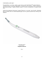
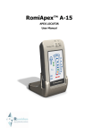
Congratulations, you have made a good choice with RomiPointerTM Implant Detector –
innovative device for precise localization of implants buried under gum tissue. Ergonomic
user-friendly design of Implant Detector makes it a choice of preference in modern dental
clinic.
Utilizing the advanced technology, Implant Detector is a precise, user-friendly, affordable
device suitable both for skilled implantologists and for general practitioners working with
implants.
RomiPointerTM
Implant Detector
Pic.1
-2-
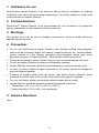
1. Indications for use
RomiPointerTM Implant Detector is an electronic device used for localization of implants
covered by gum tissue during two-stage implantology. The device enables to obtain good
results with various implant systems.
2. Contraindications
RomiPointerTM Implant Detector is not recommended for use in patients or by personnel
having a pacemaker or other implanted electrical devices.
3. Warnings
This product must only be used in hospital environments, clinics or dental offices by
qualified dental personnel.
4. Precautions
Do not use RomiPointerTM Implant Detector near devices emitting electromagnetic
noise such as fluorescent lamps, film viewers, ultrasonic devices, etc. Cellular phones,
remote controls or other devices generating electromagnetic waves may cause
abnormal operation of Implant Detector. Such devices should be turned off.
During device operation protect Implant Detector from occasional spillage of liquids.
Do not use Implant Detector in presence of flammable materials.
Implant Detector should be used with the manufacturer's original accessories only.
In order to prevent infectious agent transmission, the sensor should be changed or
sterilized between patients.
Presence of metallic bodies near the sensor may distort device indication. Avoid
presence of metallic items in the vicinity of the sensor during device operation.
For your own safety, please use personal protection gear (gloves, mask).
Implant Detector should be stored at normal environmental conditions:
- Temperature: +10 ºC to +60 ºC (+50 ºF to +140 ºF).
- Relative humidity: 10% to 90%, non-condensing.
5. Adverse Reactions
None.
-3-
6. Step-by-Step Instructions
6.1. Packaging Box Content
Check the content of the packaging box before use:
RomiPointerTM Implant Detector
AA alkaline battery
Sensor holder
Sensor
User Manual
- 1 pc.
- 1 pc.
- 2 pcs.
- 5 pcs.
- 1 pc.
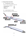
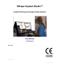
6.2. Implant Detector outlook
General view of Implant Detector is shown on Pic. 2.
LED Indicators
On/Off button
Sensor
Sensor Holder
Handle
Protective Cap
Holder lock button
Pic 22
-4-
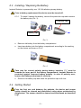
6.3. Installing / Replacing the Battery
Implant Detector is powered by one 1.5V AA alkaline primary battery.
Prior to battery replacement the device must be turned off.
6.3.1. To install / replace the battery, remove the protective cap and unscrew
the battery cap (Pic. 3).
Protective Cap
Battery Cap
Pic. 3
Remove old battery from the battery compartment
Insert new battery into the battery compartment according to the marking
on the device as shown on Pic 4.
Pic. 4
Take care for correct polarity during battery insertion ("+" must be
towards the inner part of the battery compartment). Implant Detector is
protected against incorrect battery polarity. In case of polarity error,
remove the battery and reinsert it correctly.
Screw in the battery cap and close the protective cap until click.
6.4. Getting Started
Prior the first use and between the patients, the device and sensor
holder should be cleaned and disinfected using wipes moisturized by
disinfectant. The sensor should be cleaned and autoclaved as described
in §7.
-5-
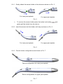
6.4.1. Gently attach the sensor holder to the device as shown on Pic. 5.
For lower jaw implants
For upper jaw implants
Pic. 5
To remove the sensor holder press the holder lock button
gently pull the holder from the device.
6.4.2. Insert the sensor into the holder until stop as shown on Pic. 6.
For upper jaw implants
For lower jaw implants
Pic. 6
6.4.3. Correct device configurations are shown on Pic. 7.
Device configuration for lower jaw implants
Device configuration for upper jaw implants
Pic. 7
-6-
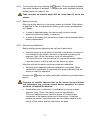
and
6.4.4. Turn the device on by pressing the
button. One short beep indicates
that audio feedback is enabled. To disable the audio feedback hold the
button pressed for about 1 sec.
Take care that no metallic object will be closer than 10 cm to the
sensor.
6.4.5. Battery check-up.
After turning the device on, the battery status is checked. If the battery
is depleted, or flat, 4 segments are flashing red 3 times accompanied
by 3 beeps.
In case of depleted battery the device may continue normal
operation before the battery is replaced.
In case of flat battery the device turns off and cannot operate before
battery replacement.
6.4.6. Self-test and calibration.
Before starting device operation the self-test is performed.
If sensor holder is not properly connected to the device or sensor is
not inserted into the holder, the error is indicated by running red
segment. After 10 sec. the device turns off automatically.
To correct the error, turn the device off, connect the sensor holder,
insert the sensor until stop and turn the device on again.
After the self-test the device performs automatic calibration.
Running green segment indicates calibration in progress. When
calibration is completed, 4 segments blink green indicating that the
device is ready for operation.
Pressing the
above.
button will restart automatic calibration cycle described
Presence of metallic objects close to the sensor during self-test
and calibration may prevent correct device operation or reduce
precision of implant localization.
If calibration error is detected, it is indicated by running orange
segment. After 10 sec. the device turns off automatically.
To correct calibration error, turn the device off, check proper
connection of the sensor holder and of the sensor. If required,
replace the sensor. Verify that there are no metallic objects in the
vicinity of the sensor and turn the device on again.
-7-
6.5. Device operation
6.5.1. When Implant Detector is ready, 4 segments blink green (Pic 8).
Pic. 8
6.5.2. Insert the device into the mouth cavity and place the sensor plane onto
the gum at some distance from the estimated position of the implant.
The central hole of the sensor should be approximately in the middle of
the jaw ridge. Slowly move the sensor along the jaw towards estimated
position of hidden implant (Pic. 9).
Pic. 9
To ensure correct measurements, take care that the sensor plane
will be always slightly pressed to the gum without gap.
Thick gum layer covering the implant may prevent correct implant
localization or reduce precision.
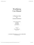
6.5.3. Implant localization
When the sensor is approaching the implant, 4 segments turn
steady green (Pic. 10a).
Continue fluent movement of the sensor in the same direction
without stopping until the segments turn orange indicating that the
sensor has passed the implant position (Pic. 10b).
Reverse direction and slowly move the sensor back along the same
path. Four segments turn green again indicating sensor movement
towards the implant (Pic. 10c). Continue sensor movement in
reverse direction without stopping.
-8-
When the sensor returns to the implant position, 4 segments turn off
and the central dot turns green indicating detection of implant
location (Pic. 10d). The visual indication is accompanied by solid
audio signal.
a
b
c
d
Sensor is
approaching the
implant
Sensor has passed
the implant position
Sensor moves
back to the
implant position
Detection of
implant location
Continue in the
same direction
Reverse direction
Continue in the
reversed direction
Pic. 10
Through the hole in the middle of the sensor mark on the gum
location of the implant using dental probe.
The sensor movement should be smooth without stopping or
unnecessary reversing the direction of the movement. This may
cause incorrect readings.
Stopping sensor movement for more than 3 sec. before
completing detection of implant location is indicated (central
green dot turns on) will cause automatic reset (4 segments blink
green). Implant localization should be repeated from the
beginning.
-9-
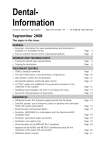
6.5.4. Cross-scanning
To improve the precision of implant localization it is possible to
perform additional cross-scanning in Buccal-Lingual direction as
shown schematically on Pic. 11.
Pic. 11
After initial implant localization as shown on Pic. 10d slowly move
the sensor in Buccal-Lingual direction pressing it slightly to the gum.
The operating sequence is similar to the sequence described in
§ 6.5.3.
Presence of metal crown, abutment, tooth with large amalgam
filling, metallic instrument close to the implant may prevent
correct implant localization or reduce precision.
6.5.5. Localization of multiple implants
In case of multiple implants, after locating and marking the first implant
continue to the estimated position of the next implant.
Slowly move the sensor along the jaw ridge. The central dot will
turn off and 4 segments will turn orange; then the segment will blink
green indicating that the Implant Detector is ready for detection of
the next implant.
Perform implant localization as described in §§ 6.5.3. and 6.5.4.
Correct localization of implant position may be impossible when 2
or more implants are too close.
6.6. Audio feedback
Implant Detector is equipped with an audio feedback which enables monitoring of
device operation additionally to visual indication. Audio feedback may be disabled as
described in s. 6.4. above.
6.7. Automatic Shutdown
Implant Detector automatically shuts down after 2 minutes without use. In order to
prolong the battery life, it is recommended to switch off the device after completing
implant localization by pressing the
button and holding it for about 1 sec.
- 10 -
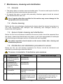
7. Maintenance, cleaning and sterilization
7.1. General
The device does not contain user serviceable parts. The service and repair should be
provided by factory trained service personnel only.
All objects that were in contact with potentially infectious agents should be cleaned
and disinfected after each use.
Use of agents other than specified in this section may cause damage to the
equipment and its accessories.
7.2. Device cleaning
Before the first use and between treatments the device should be cleaned using tissue or
soft cloth impregnated with aldehyde free disinfecting and detergent solution (a
bactericidal and fungicidal).
7.3. Sensor holder cleaning and disinfection
Before the first use and between treatments the sensor holder should be separated from
the device, cleaned and disinfected using tissue or soft cloth impregnated with aldehyde
free disinfecting and detergent solution (a bactericidal and fungicidal).
No visible impurities should remain on the sensor holder after cleaning and
disinfection process.
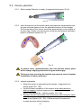
7.4. Disinfection and sterilization procedure for sensor
Before the first use and between treatments the Sensor should be disinfected and
sterilized by autoclaving as described below:
The sensor is intended for 10 sterilization cycles maximum.
#
Operation
Instructions
1
Preparation at the
point of use prior to
processing
No particular
requirements
2
Preparation for
decontamination/
preparation before
cleaning
No particular
requirements
3
Cleaning:
Automated
The sensor is not
intended for automated
cleaning
4
Cleaning: Manual
Clean the sensor with an
adequate brush or towel
soaked in a disinfectant
solution
- 11 -
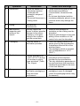
Details and Warnings
- After cleaning no visible impurities
should remain on the sensor, in
particular inside and near the
central hole
Instructions
Details and Warnings
5
#
Disinfection
Operation
- Soak the sensor in a
disinfectant solution
combined with
proteolytic enzyme if
possible
- Rinse well the sensor in
flowing water
- Follow instructions given by the
disinfectant manufacturer
(concentration, immersion time,
etc.)
- Do not use disinfectant solution
containing aldehyde, phenol or any
products which may damage the
items
6
Drying
No particular
requirements
7
Maintenance,
inspection and
testing of the
sensor
Visually inspect the
sensor to detect possible
damage to the sensor
coating or to the gold
plating of the contacts
and the central hole
- Sensors with damages or
scratches on the coating must be
discarded
- Sensors with damages to the gold
plating of the contacts or of the
central hole must be discarded
8
Packaging
Pack the sensor in
sterilization pouches
- Check the validity period of the
pouch given by the manufacturer
to determine the shelf life of the
sterilized items
- Use packaging which is resistant
up to a temperature of 141°C
(286°F)
9
Sterilization
- Steam sterilization at
134°C (273.2°F) during
18 minutes in gravity
type autoclave. (Table
Top, N type)
10
Storage
Keep sensors in
sterilization packaging in
a dry and clean
environment
- 12 -
- Follow maintenance and operation
procedures of the autoclave
provided by the manufacturer
- The only sterilization parameters to
be used are those that have been
validated and provided to the user
in this User Manual
- Sterility cannot be guaranteed if
packaging is open or damaged
(check the packaging before using
the sensors)
8. Troubleshooting
Please review the suggested solutions before calling customer service.
#
1
Problem
The device does not turn
on by pressing
button.
Possible Cause
Solution
1. Button malfunction
1. Press the
button
several times.
2. Flat battery.
2. Replace the battery.
3. Electronic
malfunction.
3. Contact your
customer service.
2
No sound while measuring.
Audio feedback is
disabled.
Turn the device Off and
then turn it On. One
short beep indicates
that audio feedback is
enabled.
3
Device cannot indicate the
location of the implant.
1. Sensor is
disconnected
1. Turn the device Off,
remove the sensor,
clean contact
surfaces of the
sensor and reinsert it.
Turn the device On
again.
2. Damage to the
Sensor, sensor
coating or sensor
contacts
2. Replace the Sensor.
3. Sensor holder is
damaged;
Bad contact
3. Replace the Sensor
holder.
4. Electronic
malfunction.
4. Contact your
customer service.
- 13 -
9. Warranty
Implant Detector is warranted for 24 months from the date of purchase. The accessories
(sensor holder and battery) are warranted for 6 months from the date of purchase.
The warranty is valid for normal usage conditions. Any damage caused by accident, abuse,
misuse, or as a result of service or modification other than by a person authorized by the
manufacturer will render the warranty void. The warranty is in lieu of any other warranty
expressed or implied.
Sensors are disposable and are not covered by warranty.
10. Disclaimer
The manufacturer, its representatives and its dealers shall have no liability or responsibility
to customers or any other person or entity with respect to any liability, loss or damage
caused or alleged to be caused directly or indirectly by equipment sold or furnished by us,
including, but not limited to, any interruption of service, loss of business or anticipatory
profits, or consequential damages resulting from the use or operation of the equipment.
The manufacturer reserves the right to implement changes and modifications of the
product at any time, to revise this publication and to make changes in the contents hereof
without obligation to notify any person of such changes, modifications or revisions.
11. Certification
Implant Detector complies with IEC 60601-1:2005 (Safety) and IEC 60601-1-2:2007
(Electromagnetic compatibility) standards, including conducted and radiated immunity tests
as specified for equipment of Group 1 Class B.
12. European Authorized Representative
European Authorized Representative who has been empowered to enter into commitments
on our behalf:
Obelis s.a
Bd. Général Wahis 53
1030 Brussels, BELGIUM
Tel: +(32) 2.732.59.54
Fax: +(32) 2.732.60.03
E-Mail: [email protected]
- 14 -
13. Technical Specifications
Implant Detector belongs to the following category of medical devices:
Internally powered equipment
Type B applied parts
Not suitable for use in the presence of flammable anesthetic mixtures with air, oxygen or
nitrous oxide
Continuous operation
Ingress of liquids – not protected
The device is intended for indoor use only
Environmental conditions during transportation:
- Temperature: –20 ºC to +60 ºC (0 ºF to 140 ºF)
- Relative humidity: 10% to 90%, non-condensing
Implant Detector is intended for use in electromagnetic environment specified for
equipment of Group 1 Class B.
Specifications:
Dimensions:
Weight:
Type of display:
Power source:
215 x 45, dia. 21 mm
60 gr.
LED segments
1 x 1.5V AA alkaline primary battery
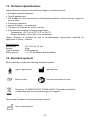
14. Standard symbols
Device marking includes the following standard symbols:
Type B applied part
Manufacturer
Direct current
Consult instructions for use
1.5V
Recycling : PLEASE DO NOT THROW AWAY! This product and all its
components must be recycled through your supplier
Device label includes the following standard symbol:
Date of manufacture
- 15 -
RomiPointerTM Implant Detector
Manufacturer
Romidan Ltd.
5 Simcha Holzberg St.,
5502213 Kiryat Ono, Israel
Email: [email protected]
www.romidan.com
Rev. 01 – 05/2015