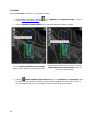
1
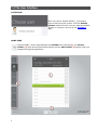
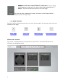
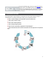
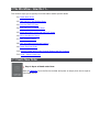
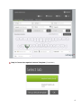
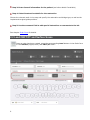
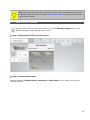
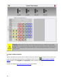
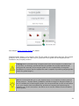
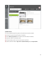
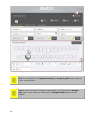
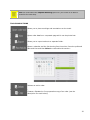
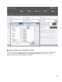
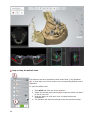
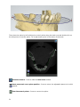
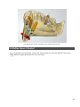
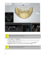
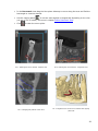
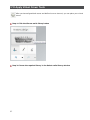
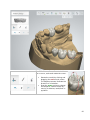
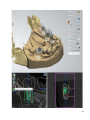
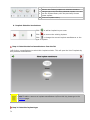
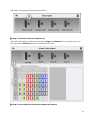
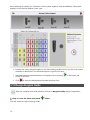
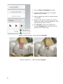
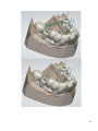
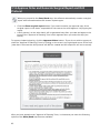
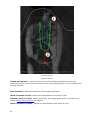
3Shape Implant Studio™
Implant Planning and Surgical Guide Solution
User Manual
www.3shape.com
Rx only
16/07/2014
IS-2.1.9.0-E-EN
Table of Contents
1 Introduction .................................................................................................................... 1
1.1 Intended Use ............................................................................................................. 2
1.2 Indications for Use ..................................................................................................... 2
1.3 Software Device Performance ...................................................................................... 2
1.4 The User Interface...................................................................................................... 3
1.5 Workflow Overview ..................................................................................................... 6
2 The Workflow - How Do I ?... ............................................................................................ 7
2.1 Create New Order ...................................................................................................... 7
2.2 Load CBCT/CT and Surface Scans ................................................................................. 9
2.3 Crop the CBCT/CT Scan ............................................................................................ 11
2.4 Align CBCT/CT to Surface Scan .................................................................................. 12
2.5 Setup Panoramic Curve and CBCT Views ..................................................................... 14
2.6 Define Mandibular Nerve ........................................................................................... 14
2.7 Place Virtual Crowns ................................................................................................. 16
2.8 Place and Optimize Implant Position ........................................................................... 17
2.9 Create Surgical Guide ............................................................................................... 21
2.10 Approve Order and Create Surgical Report and Drill Protocol ........................................ 25
2.11 Send / Export Data Files .......................................................................................... 26
3 Your Tools and Settings .................................................................................................. 27
3.1 Order Form ............................................................................................................. 27
3.2 Load CBCT/CT and Adjust CBCT/CT Scan Visibility ........................................................ 31
3.3 Load Surface Scan and Optimize Visibility.................................................................... 34
3.4 Crop the CBCT/CT Scan ............................................................................................ 35
3.5 Align the CBCT/CT and the Surface Scans ................................................................... 37
3.6 Visualize Your Settings and Options ............................................................................ 43
3.7 Setup Default Views and User Interface ...................................................................... 47
3.8 Define Panoramic View.............................................................................................. 50
3.9 Define Nerve Channel ............................................................................................... 54
3.10 Apply Virtual Crown Tools ........................................................................................ 57
ii
3.11 Apply Implant Planning Tools ................................................................................... 62
3.12 Use the Implant Library ........................................................................................... 70
3.13 Design Surgical Guide ............................................................................................. 73
3.14 Approve Order and Generate Surgical Report and Drill Protocol .................................... 83
3.15 General Settings..................................................................................................... 84
4 Communicate and Export / Import Design Data ................................................................. 97
4.1 Export / Import Your Planning and Guide Design Data .................................................. 97
4.2 Communicate With My Partner IPS Software ................................................................ 98
4.3 3Shape Dental System™ ........................................................................................... 99
4.4 3Shape Communicate™ ............................................................................................ 99
5 System Settings .......................................................................................................... 101
5.1 System Requirements ............................................................................................. 101
5.2 Setup Network Installation ...................................................................................... 101
6 Manufacturer Information ............................................................................................. 102
7 Warnings and Precautions ............................................................................................. 103
8 Information on the CBCT/CT Scanning............................................................................ 107
1 Introduction
3Shape Implant Studio™ is a pre-operative planning software used to plan the placement of one
or more implants based on an imported and aligned Computer Tomography (CT) and 3D surface
scan. The implants are provided by a secure implant library. In addition, a surgical guide for a
guided surgery can be designed and exported for 3rd party fabrication based on the approved
implant position and a specified sleeve file defined by the manufacturer. The use of the software
requires having the necessary expertise in implant dentistry.
Implant Studio™ provides a method of importing medical imaging information from radiological
imaging systems, such as CT combined with an optional 3D surface scan, to a computer. Visual
representations of the imaged anatomical structures (e.g. the jaw with teeth and roots) are
derived allowing for a three-and two-dimensional assessment of the patient without patient
contact.
Implant Studio™ adds features for pre-operative simulation of dental implant placement and
surgical treatment options and allows the user to visualize the placement of dental implants and
other planning objects (like mandibular nerve canals and virtual crowns) within the visualized 3D
volume data. Thus, dental professionals, like implantologists, are able to precisely plan the
positions, orientations, types and sizes of implants, which are to be placed in the patient's
mandible/maxilla, together with the related surgical procedures keeping the aesthetic aspect in
mind. Build-in safety feature, like collision detection and safety zone, minimize the risk of harm to
the patient to the highest possible degree.
The case planning can be used to generate an output (STL-file) for a surgical drill guide, thus
transferring the virtual case planning into physical tools enabling the surgical installation
according to the virtual case planning.
Surgical drill guides are patient specific templates, which are intended to transfer the preoperatively determined positioning of the dental implants to the patient intra-operatively, which
will assist the surgeon in placing dental implants by guiding and marking drill locations and assist
during the implant insertion.
A surgical report allows the user to share the planning case with others and to approve the case, if
the planning has been done by a 3rd party. After the final case approval, a drill protocol is
provided listing the needed parts to be ordered for the implant surgery and summarizing the
planned surgery. The position of the virtual crown can be transferred to 3Shape Dental System
Lab software to design the temporary or final abutment(s) and restoration(s) as indicated in the
order form.
1.1 Intended Use
3Shape Implant Studio™ is a pre-operative planning software for the placement of dental
implant(s) based on imported CT image data, optionally aligned to an optical 3D surface scan. The
CT image data are provided from medical scanners such as a CBCT/CT scanner. Virtual Crowns
can be used for optimized implant positioning under the prosthetic aspect. Furthermore, a surgical
guide for use with guided surgery can be designed based on the planned implant position(s). The
surgical guide data can be exported for manufacturing on an external system.
Use of the software requires that the user has the necessary medical training in implantology and
surgical dentistry.
Warning! The US Federal law restricts this device to sale by or on the order of a
dentist.
1.2 Indications for Use
The 3Shape Implant Studio™ software is indicated for use as a medical front-end software that
can be used by medically trained people for the purpose of visualizing gray value images. It is
intended for use as a pre-operative software program for simulating/evaluating dental implant
placement and surgical treatment options.
Indications of the dental implants do not change with guided surgery compared to conventional
surgery.
Contraindications: Pre-operative planning with Implant Studio™ must only be applied if
additional radiation dose from 3D radiology (compared to conventional x-ray) can be justified.
1.3 Software Device Performance
Implant Studio™ has been developed with the intention of providing maximum safety and
accuracy in regard to planning of the implant positions and the design of surgical guides. The
actual performance of the software is limited by the quality, resolution and accuracy of its input
data (DICOM CBCT/CT and eventual surface scan) and by the user’s decisions on how to define
the input data’s alignment. The actual implant planning process and surgical guide design can only
be performed within the limitations defined by the input data and their alignment. The input data
and alignment also defines the achievable degree of accuracy of all measurements.
The software does not apply any modifications, compression, or alterations to the input data
(DICOM and eventual surface scan) during their upload, alignment, usage and/or export.
Implant Studio™ DICOM Conformance Statement is available for download here:
http://www.3shapedental.com/implant-studio-DICOM-conformance-statement
Overall, the intended use of the software is considered to be safe if used correctly and while
taking the necessary precautions. The medical benefits outweigh the overall residual risk.
2
1.4 The User Interface
LOGIN PAGE
When you launch Implant Studio™, you need to
login to start using the system. Click the Default
operator button to enter. You can setup the default
operator or create a new one on the Configure
page.
HOME PAGE
Implant Studio™ Home page displays the Calendar with sessions (1), the Service
toolbar (2) with various options and settings and the Main toolbar (3) which helps you
navigate through the application.
3
•
(1) CALENDAR
Allows you to create new sessions. Please see chapter Order Form for details.
•
(2) SERVICE TOOLBAR
o
o
o
o
Contains a list of patients, their sessions and information on every order,
including images of scans. Enter patient's name in the Search field to find his
sessions.
Allows you to create a new order for the selected patient - click the New
session button to open the Order Form.
Displays a calendar with existing sessions and available time for new
sessions.
Allows you to create a new order - click on the empty time field in Calendar
or the
button to open the Order Form.
o
Opens a list of existing orders and allows you to search orders using various
filters.
o
o
Opens an inbox with the incoming system and external messages. When a
new message(s) arrives, a red square with a number of unread messages
appears on the tab.
Informs you when your Implant Studio™ system receives an order with the
Surface scan - a number of newly arrived orders appear in a green square on
the tab. Click on the message to open the order on the Order form page. The
order itself is automatically stored under Cases.
o
Allows you to setup your Implant Studio™ system. See chapter General
Settings for details.
o
o
o
o
o
Online Support - launches a screen sharing session for online support.
Training Center - opens a dialog window with training videos.
User Manual - opens Implant Studio™ online help.
Safety Guide - opens Implant Studio™ Safety Guide.
Terms of Service - opens the document with 3SHAPE SOFTWARE GENERAL
LICENSE TERMS AND CONDITIONS.
Third Party Licenses - displays information on the external applications
used in Implant Studio™.
Send feedback - opens a form for reporting an eventual system
malfunction.
Close - closes the Help window.
o
o
o
4
o
o
o
Logout - signs the user out and displays the Login page.
Shutdown - turns off the Implant Studio™ system (a confirmation dialog
window appears to make sure you want to shut down Implant Studio™).
Cancel - closes the window and returns to the Main page.
The Close and Help windows also contain information on the Implant Studio™
version you are currently using.
•
(3) MAIN TOOLBAR
The Main Toolbar provides easy access to the main software pages. It can appear both at the top
or bottom of the page:
Home page
Order form
Workflow page
Communicate page
WORKFLOW TOOLBAR
The process of implant planning is comprised of a succession of important steps which are
reflected in the Workflow toolbar:
5
To open the Workflow page, click the corresponding button in
the Main toolbar. The window will open on the Cropping page
allowing you to crop the CBCT scan. Note that some of the
steps will remain disabled until the previous step is completed
or in case an error was made during planning (e.g. implantnerve collision).
1.5 Workflow Overview
The Implant Studio™ typical workflow in combination with other Dental software packages is
illustrated below. The steps are described in detail in the corresponding chapters.
Step 1: Load and align open format CBCT scan and surface scan
Step 2: Place virtual crowns
Step 3: Plan implant positions
Step 4: Design surgical guides
Step 5: Create restorative components in Dental System™
Step 6: Communicate with a dentist and receive his final approval of the planned
case
6
2 The Workflow - How Do I ?...
This section helps you to quickly find information about specific tasks:
2.1 Create New Order
2.2 Load CBCT/CT and Surface Scan
2.3 Crop the CBCT/CT Scan
2.4 Align CBCT/CT to Surface Scan
2.5 Setup Panoramic Curve and CBCT/CT Views
2.6 Define Mandibular Nerve
2.7 Place Virtual Crowns
2.8 Place and Optimize Implant Position
2.9 Create Surgical Guide
2.10 Approve Order and Create Surgical Report and Drill Protocol
2.11 Send / Export Data Files
2.1 Create New Order
Step 1: Open a blank order form
Open a Calendar from the Service toolbar and press an empty time slot to open a
new Order Form:
Step 2: Choose the required Lab and Template (if available)
8
Step 3: Enter General information for the patient (and other details if available)
Step 4: Select Construction details for the restoration
Choose the relevant teeth in the map and specify the restoration and bridge type, as well as the
implant and surgical guide positions.
Step 5: Use the comment field to add special instructions or comments to the lab
See chapter Order Form for details.
2.2 Load CBCT/CT and Surface Scans
Once an order has been created, press the corresponding Load buttons in the Order form
to load Surface (upper/lower) and CBCT/CT scans:
9
See chapters Load CBCT/CT and Adjust CBCT/CT Scan Visibility and Load Surface Scan and
Optimize Visibility for details.
For the CBCT/CT scans, 3Shape Implant Studio™ supports all open DICOM .dcm file formats,
which comply with the 3Shape DICOM Conformance Statement. In case a DICOM .dcm fails to
load, it can be due to a corrupted file structure or that the file fails to comply with the quality
check during loading (please see hint below for further instructions).
Hint! In case a DICOM .dcm fails to load, please check the 3Shape DICOM
Conformance Statement on our website or in chapter Information on the CBCT/CT
Scanning of the manual. Alternatively, please contact the original CT manufacturer for
clarification.
3Shape Implant Studio™ allows to import open format STL files and 3shape .dcm surface scans.
In case it fails to load, please check the quality of the surface scan and the used triangulation
settings.
Warning! Make sure that the quality of the loaded CT scan is sufficient for planning the
case and that the relevant areas on the image for the bone analysis are adequate in
order to make an accurate and sustainable decision for implant planning and surgery!
Hint! Please use the visualization settings for the CBCT/CT scan and the ability to
adjust the grey values to find the optimum for each individual scan.
Warning! User needs to ensure that the surface scan is of the required quality for
planning the case, and that the relevant areas for the implant planning and placing the
surgical guide fully exist.
Hint! Please check that the scan data are correctly and completely loaded.
10
Hint! Please check that the visualization of the CBCT and Surface Scan is working
correctly to allow a secure and accurate placement of the implant during the navigated
planning and surgical guide design process.
Hint! To assure optimal scan quality, please make sure that the surface scan is taken
with a reliably functioning 3D scanner, and the scanner has recently been calibrated.
2.3 Crop the CBCT/CT Scan
Once the order has been created and scans loaded, click the Workflow page button in
the Main toolbar. The software will automatically bring you to the first step - Cropping,
where you can reduce the scan size by cropping the CBCT/CT scan and keeping only that
part of a scan that will be used for planning.
(1)
(2)
(3)
(4)
(5)
Axial plane
Coronal plane
Sagittal plane
Graphics information
Cropping information
Please see chapter Crop the CBCT/CT Scan below for details.
11
2.4 Align CBCT/CT to Surface Scan
Once the cropping of the CBCT/CT was done (optional), you can proceed to the Scan
alignment step. To align the CBCT/CT and Surface scans, please follow steps below:
Warning! Implant Studio™ must not be used for aligning CT and 3D optical surface
scans in edentulous cases! The available alignment tools are not suited for achievement
of reliable and accurate alignment results!
Step 1: Place the alignment points
Place 3 points on the Surface scan in the left pane and 3 corresponding points on CBCT/CT scan
in the right pane for correct alignment of the scans. The scans are automatically aligned after
placing the points on marking the Confirmation checkbox while the Surface and CBCT/CT
windows get hidden.
Step 2: Check and correct the alignment if necessary
Use the following tools to check and improve the alignment:
•
Region of interest tools
•
Difference map
•
2D mode in the CT pane
•
2D cross section
Step 3: Confirm Alignment
Approve the alignment by marking the Confirm alignment checkbox.
12
See chapter Align the CBCT/CT and the Surface Scans for more information.
Warning! Before clicking the Confirm Alignment check-box, please assure that the
CBCT/CT and surface scans are well aligned, particularly in the area(s) where the
implant(s) will be placed. Please check these also for the alignment in the 2D cross
section views.
Note! You must confirm the alignment with a click on the Confirm Alignment in order
to be able to proceed to further steps which otherwise appear disabled.
Hint! Place the 3 points in approximately the same place and same order in both scans,
and ensure that the area is clearly visible in both scans. The optimal alignment should
be reached within the area where the implant(s) are placed later. Please use also the
cross-section views to check the alignment!
13
Hint! Please assure that the visualization of the CBCT/CT and surface scans appear
correct and complete.
2.5 Setup Panoramic Curve and CBCT Views
After aligning the two scans, proceed to the next step Panoramic curve where the
panoramic view for the CBCT scan can be defined:
Using the cursor, click the points along the arch to define the panoramic curve (2):
(1)
(2)
(3)
(4)
(5)
(6)
(7)
(8)
Matched surface and CBCT/CT scans.
Green panoramic curve drawn with the cursor.
The blue lines indicate the depth of the CT scan shown in the panoramic curve view.
The orange line indicates the section view along the panoramic curve.
The panoramic curve view.
Cross-section view within the blue lines called the Sagittal view.
Section view defined by the orange line called the Tangential view.
Visualization sliders.
See chapter Define Panoramic View for details.
2.6 Define Mandibular Nerve
14
To define a nerve channel on the Nerve definition step, use the panoramic view, two
cross section views and the 3D view to help you assess the CBCT/CT scan from different
angles and place the nerve correctly. See chapter Define Nerve Channel for details.
Warning! Please make sure, that the nerve is correctly placed and that you have
chosen the appropriate size of the nerve channel diameter to compensate for potential
inaccuracies in the nerve position!
Warning! If the nerve position is not clear due to poor CBCT/CT image quality, the
dataset must not be used!
15
Hint! Please ensure that the nerve channel is clearly visible in the different views after
it is placed. Please see also the chapter Define Nerve Channel to learn more about how
to place them correctly.
2.7 Place Virtual Crowns
Once the panoramic curve has been defined, press the Anatomy design button in the
Workflow toolbar to start placing virtual crowns.
Step 1: Select desired smile from the library
Step 2: Shape virtual crowns
Use the necessary Transformation, Morphing and Wax Knife tools to shape the crowns as
illustrated below.
16
Hint! Please assure that the selected crown design correlates with the intended final
design.
Hint! The positions of the virtual crowns need to be approximated to the intended final
restoration position.
See chapter Apply Virtual Crown Tools for details.
2.8 Place and Optimize Implant Position
Once the virtual crowns have been placed, press the Implant planning button in the
workflow toolbar to start planning implants:
17
Step 1: Select implant manufacturer
Press the green plus button in the Implant selection menu and
select the implant manufacturer from those displayed.
Step 2: Select an implant from the manufacturer
Warning! Be aware that not all displayed implant systems may have regulatory
clearance in all countries. Please direct any questions regarding regulatory status in
your country towards the implant manufacturer or reseller.
Double-click the implant to select it and close the Select implant window.
Once an implant is selected, its model appears in the 3D and 2D views of the main window.
18
Warning! Please make sure that the correct implant type incl. platform type/ length
and diameter is chosen according to the patient clinical situation. Please consider this in
particular when planning an implant case near a main anatomical feature like artery or
alveolar nerve!
Step 3: Adjust implants
Adjust implants and optimize their positions using the 2D views at the bottom of the screen, the
Enable implant aligned
main 3D modeling window and the Visualization sliders. Use the
plane button in the Sagittal and Tangential views to enable a plane centered around an
implant.
Please see chapter Apply Implant Planning Tools for details.
19
Warning! Please assure the correct minimum size of the safety zone for the implant
and mandibular nerve. A collision of the implant with the nerve, another implant or any
other main anatomical structure like nerve or artery can cause severe damage,
paresthesia and complication to the patient! (see chapter Apply Implant Planning
Tools). For further information on how to change the safety zone size, please see
chapter General Settings - Planner and Guide.
Warning! In case of collision between implant and nerve or between implants, the
software will disable access to further steps i.e. creation of report, protocols as well as
the surgical guide design step.
20
Warning! Please assure that an implant does not collide with an existing implant or
tooth root channel. Also assure that the implant does not penetrate the jawbone
border.
Warning! During implant placement, please consider that the bone-density in reality
can be different than the visualized bone-density displayed on the screen. Please see
section Load CBCT/CT and Adjust CBCT/CT Scan Visibility for more details.
Hint! Please assure that the chosen implant position corresponds to the intended
restoration position and the fixation/mounting method for the prosthesis on the
implant.
Warning! The user must be able to recognize red and green colors to detect warnings
such as “Collision between implant and nerve”.
2.9 Create Surgical Guide
Once implants have been placed and positioned, you can press the Surgical Guide button
in the Workflow toolbar in case you want to create surgical guides.
Step 1: Place the splines to mark the surgical guides' outlines
Press the Start new patch
button to enable a spline-placing mode and create one or
several patches (you can place a few splines if necessary). Make sure you select the correct
manufacturer under Settings.
21
Warning! Please assure that the required material thickness and offset parameters are
applied when creating the surgical guide – according to the specific material and
manufacturing machine requirements you will use.
Warning! Please check for potential collision between the sleeves, the visualized drill
cylinders and any existing tooth or dental restoration and consider the consequences for
the intended treatment procedure. Note that in case of the sleeve collision, all further
steps will be disabled.
Warning! The surgical guide should sit stably and firmly on the teeth, and it must not
move during surgery. This is to ensure optimal guidance for the drills and implants
during surgery. Do not use the surgical guide unless you judge the fit to be
optimal, safe and completely correct.
22
Hint! Please design the surgical guide in such a way that sharp edges are avoided.
Hint! As you design the surgical guide, ensure that there is sufficient support and
connection between the main structure and the support for the sleeves.
Step 2: Create a surgical guide
Press the Preview button to create the surgical guide.
Step 3 (optional): Add bars and windows
23
See chapter Design Surgical Guides for details.
3Shape Implant Studio™ will create an open STL-file ready for export after approval. This surgical
guide STL file is intended to be used only for production of the guide and not supposed to be
modified in any 3rd party solution.
Warning! Before you start using a surgical guide from a new supplier or machine for
the first time, we strongly recommend that you validate the physical and functional
quality plus the accuracy of the surgical guide! It is the responsibility of the guide
manufacturer to ensure that the equipment used is capable of producing surgical guides
suitable for guided surgery.
Hint! We recommend that you or your supplier apply a 3D inspection solution and the
3Shape protocol: “Implant Studio_Validation Procedure to Approve Surgical Guides” in
order to validate the printed surgical guides. We recommend that you do so both before
you or your supplier start manufacturing, and also at frequent intervals during the
production run. In this connection, we advise you to use the 3Shape Convince Quality
Control System.
24
Hint! Please make sure that the Surgical guide is adequately disinfected.
2.10 Approve Order and Create Surgical Report and Drill Protocol
When you proceed to the Save/Send step, the software automatically creates a
surgical report which is intended to be used for the review and approval
procedures.
A drill protocol, however, will be generated only after you read and agree to the
terms of the "Approval of Planning" form which appears when you enter the step.
•
•
Step 1: Go to the Save/Send step
The "Approval of Planning" form appears on the screen.
Step 2: Read carefully and agree to the terms of the "Approval of Planning" form
Step 3: View the created surgical report and a drill protocol by clicking the
corresponding buttons
The Surgical report file can be sent out via e-mail or 3Shape Communicate.
See a detailed chapter below Approve Order and Generate Surgical Report and Drill Protocol for
more information.
Warning! Please make sure that the presented screenshots and information for the
implant positions and implant types as well as, eventually, the surgical guide in the
Surgical report are sufficient in order to make a clear and safe decision to approve or
modify the implant or surgical guide position and design.
Warning! Please follow the instructions in the drill protocol!
Hint! Please check the Surgical report and Drill Protocol every time before a surgery
and make sure that
•
25
the provided information is correct
•
you ordered correct implants based on their order number
•
the right drills and sleeves are used for the selected implant type and
manufacturer
•
drills and sleeves are in a good condition and ready to be used for the surgery
2.11 Send / Export Data Files
When you proceed to the Save/Send step, the software automatically sends the order to
your partner via 3Shape Communicate IF two conditions are met:
1. You configured your Implant Studio™ Connection settings under the Configure tab.
2. You read and agreed to the "Approval of Planning" form which appears when you enter the
Save/Send step.
After you have agreed to the "Approval of Planning" form, the order is automatically sent. If the
software was not set up to send orders via 3Shape Communicate, then the output files can be
found in the output folder.
In case a surface scan was used together with a CBCT/CT scan for planning, Implant Studio™ will
export/send the approved implant position and surface scan as a 3Shape .dcm file. This file can be
imported into any 3Shape dental software application.
See chapter Communicate and Export / Import of Design Data for details.
26
3 Your Tools and Settings
Implant Studio™ offers a variety of tools and settings for your implant planning and surgical guide
design. See chapters below for details.
3.1 Order Form
OPENING THE ORDER FORM
•
To open the Order Form and create a new order, click on the empty time field (1) in the
Calendar or the
•
button (2):
You can also create a new order for the existing patient through the Patients tab by
clicking the New session (3) button:
ORDER DETAILS
Fill in the provided fields with the patient's information and construction details:
(1) Choose the required Lab and Template (if available).
(2) Enter General information for the patient (and other details if available).
(3) Upload the CBCT/CT and Surface scans.
(4) Choose necessary teeth in the overview map with a left click.
(5) Specify restoration details: Type, Color, Implant Planning and/or Surgical Guide.
28
Note! The availability of the Implant Planning and Surgical guide options depends
on your license version.
Note! In order to be able to create a surgical guide, you must select the Surgical
guide option in the order form. Otherwise, the Surgical Guide step will not be
available.
29
Note! You must select the Implant Planning option for your order to be able to
proceed to the next step.
TOOLS AND OPTIONS
Allows you to place markings and annotations on the teeth.
Opens order details on a separate page which can be printed out.
Allows you to export orders to a separate folder.
Opens a calendar and the list showing free time slots. Press the preferred
date and time and then Select to reschedule the session:
Deletes an entire order.
Creates a Standard or Pre-preparation copy of an order (see the
description for each below):
30
3.2 Load CBCT/CT and Adjust CBCT/CT Scan Visibility
UPLOAD CBCT/CT SCAN
Step 1: Click the CT scan Load button in the Order form
Step 2: Go to the folder containing the DICOM CBCT/CT scan and select a .dcm scan
file
Step 3: Press Open
31
Step 4: Preview scans in the CBCT/CT loader
The CBCT/CT loader will assist you with selecting the correct scan by placing the available scans
into two categories: Supported scans and Unsupported scans. Click the scan to read
additional information in the window to the right.
32
Step 5: Confirm the selected scan to upload it
Select the supported scan you want to load and then click the Confirm button to upload the
CBCT/CT scan.
A green tick will appear in the CT scan check-box after the successful upload:
ADJUST CBCT/CT SCAN VISIBILITY
Hint! Please use the visualization settings for the CBCT/CT scan and the option to
adjust the grey values in order to find the optimum for each individual scan.
33
Step 1: Click the CT visibility button
below the Visualization sliders
This will open the CT Element Visibility with the
sliders for Air, Skin, Bone and Enamel
visibility.
Step 2: Click and drag the sliders to setup
the desired CBCT/CT scan visibility
•
Move sliders to the left/right to change
the voxel intensity.
•
Move handles up/down to adjust the
opacity.
Hint! Please ensure that the points
representing bone, skin, enamel and
enamel end represent correctly the
different body parts and do not cause
misinterpretation.
3.3 Load Surface Scan and Optimize Visibility
UPLOAD SURFACE SCAN
Step 1: Click the Load button for upper/lower jaw in the Order form
Step 2: Select a surface scan file from the selection window that appears (.stl and
3Shape .dcm formats are supported)
Step 3: Click Open
34
A green tick will appear in the Upper/Lower jaw scan check-boxes after the successful upload:
OPTIMIZE VISIBILITY
Use the Preparation slider
to toggle the visibility of the Surface scan. Click on
slider's icon to hide the scan completely.
3.4 Crop the CBCT/CT Scan
Once the order has been created and scans loaded, click the Workflow page button in
the Main toolbar to start the Implant planning process:
35
The software will automatically bring you to the first step - Cropping, where you can reduce the
scan size by cropping the CBCT/CT scan and keeping only that part of a scan that will be used for
planning.
(1)
(2)
(3)
(4)
(5)
Axial plane
Coronal plane
Sagittal plane
Graphics information
Cropping information
All three windows provide different views of the - (1) Axial, (2) Coronal and (3) Sagittal and
each has a slide bar which you can move sideways to look through the slices of the CBCT scan
and better see which part to crop.
Click and drag the blue cropping box inside the windows to select the part of the CBCT/CT scan
that you wish to work with (area outside the box will be deleted)
In the (4) Graphical information window you can view information on your video card and the
size of the original CBCT/CT scan.
36
The (5) Cropping information window shows the size of the new cropped scan and if it is too
small, the Volume region field displays Invalid and you will not be able to continue with Implant
planning unless you crop the CBCT/CT scan correctly (in which case the field will display Valid).
3.5 Align the CBCT/CT and the Surface Scans
To align the CBCT/CT and Surface scans, please follow steps below:
Step 1: Place three corresponding points on each scan
Place 3 points on the CT scan in the left 3D pane and 3 corresponding points on the Surface scan
in the right 3D pane - the scans will automatically align after you place the last point. You can
move the points in order to correct the alignment, or remove the points all altogether to start
over.
Hint! Please use only the teeth area while placing the three points for both CBCT/CT
and Surface scans. Please do the same while using the Region of Interest tool.
When moving the cursor over the CT/Surface panes, the following buttons appear:
37
•
The Clear the points
•
The Lock views
scans during rotation.
•
The Switch to 2D mode
are aligned:
button lets you remove incorrectly placed alignment points.
button lets you lock and synchronize the movement of the two
button (CT pane only) becomes available after the scans
o Click the button to use a cross section plane for evaluation of the alignment.
o Move and rotate the plane to place it in the necessary position.
o Click Reset cross section plane to return the plane to its initial position.
o Place the measurement points on the CT and Surface scans with a mouse click to
measure the distance between scans if necessary.
o Click the Enable Threshold highlighting
button to highlight with green
those areas on the CT scan which are used for the base alignment between the CT and
surface scans. These areas, which are marked green, are defined by the Threshold (HU)
slider (see 'Step 2' below).
38
Step 2: Check and correct the alignment if necessary
•
39
Threshold (HU)
The Threshold (HU) slide bar lets you adjust
the Hounsfield scale for the enamel in the CT
scan, the effect of adjustment is shown on the
images:
40
•
Region of interest
Manually improve the alignment by marking with the cursor a specific area on the Surface Scan in
the 3D pane to perform a regional alignment optimization for the selected areas.
Add - lets you mark the area of greater importance for the alignment algorithm.
Remove - removes only the part of the marking indicated by the cursor.
Clear selection - clears all your previous marking.
•
Difference Map
Click the Show difference map
button to view the alignment result with the help of a color
scale. Please pay special attention to the areas marked red and blue - they might require
additional alignment, e.g. with the help of the Region of interest tool.
41
You can also use 2D Cross Section to check the alignment.
Step 3: Confirm Alignment
Approve the alignment by marking the Confirm alignment checkbox. The CT and Surface panes
get hidden.
42
Note! The scans alignment must be performed in order to proceed to further steps
which, otherwise, appear disabled.
3.6 Visualize Your Settings and Options
The visualization tools can help you while planning implants and
designing surgical guides.
Right-click anywhere in the modeling window to open the
visualization tools menu. Three tools are available:
1. Visualization sliders
2. Measurement tools
3. 2D cross-section
VISUALIZATION SLIDERS
43
Use the Visualization sliders to turn on/off the
visibility of
•
•
•
•
•
•
•
•
•
•
scans
bone
enamel
skin
opacity
contrast
brightness
sleeve with implant insertion direction
drill diameter
etc.
You can pin the slider to the modeling window and
set up the default views (see Setup Default Views
and User Interface for details).
Note! Only sliders that are relevant for
the current step will be available.
MEASUREMENT TOOLS
Right-click the 3D scan on the Implant Planning step
and click one of the measurement options to let the
software automatically measure the distance from:
Implant to implant – shows the shortest distance to next neighboring implant.
Implant to nerve - shows the shortest distance from implant to nerve.
44
Implant to surface – shows the shortest distance from implant to surface scan.
2D CROSS-SECTION
Use the cross section to create a 2D cutting plane at a position of
your choice. You can also use the tool to define a free definable
cutting plane to inspect the implant position in the 2D format.
•
•
•
45
Draw a section line across the model by holding down the
left mouse button.
To rotate the 2D plane, click and drag a red control point
or a blue rim (see image below).
To move the 2D plane alongside the scan, click and drag a
blue control point.
After you have placed the cross section plane, a 2D preview window appears in the bottom left
corner.
46
•
•
•
•
•
•
Move the mouse cursor over the window and scroll to zoom the sectioned area in/out.
Press down the mouse wheel to move the cross section in the preview window.
Move the preview window within the screen by clicking and dragging the green border of a
window (mouse cursor changes into a "hand").
Change the window's size by clicking and dragging its borders (mouse cursor changes into
arrows).
Place two points to measure the distance between objects (see image above).
Click the green cross button to close the 2D cross section tool.
Hint! To enlarge the 2D cross section window, move the cursor over it and press 'E' on
your keyboard.
3.7 Setup Default Views and User Interface
During implant planning you can use the visualization sliders to toggle the visibility of objects in
the modeling window, as well setup the default views.
Step 1: Open the right-click menu
Right-click in the modeling window to open the menu.
See chapter Visualize Your Settings and Options for details on the right-click menu.
Step 2: Pin the sliders to the modeling window
For easier access, you can display the visualization sliders in the modeling window by clicking the
Pin
47
icon.
Step 3: Use sliders to control the visibility of objects
With the sliders accessible from the modeling window, they can be used for turning the visibility of
scans on/off, controlling the brightness, setting contrast etc. Drag the sliders sideways or click
their icons to toggle the visibility of items.
48
Step 4: Setup the default views
The software can save the default views under the 1 / 2 / 3 buttons
(1), so that when you click a number, the corresponding default view is
displayed.
To save the default view:
1. Press Shift and click one of the numbers.
2. Select the desired check-boxes (2) to mark the sliders you want
to use for the view.
3. Drag the sliders or click their icons to setup the desired
visualization.
4. The software will save the settings under the selected number.
49
3.8 Define Panoramic View
After aligning the two scans, proceed to the next step where the panoramic view for the
CBCT/CT scan can be defined. This will allow you to view the scan from different angles:
(1)
(2)
(3)
(4)
Axial view
Panoramic view
Sagittal view (blue)
Tangential view (orange)
•
Every view is shown in its own box.
•
The cross section plane is defined by a specific color - blue for Sagittal and orange for
Tangential.
•
You can move along the axis of a view by hovering the cursor over the view and scrolling
with the mouse wheel while pressing Ctrl (see image above).
•
If you scroll in any view window, the zoom in/out operation will be applied.
(1) Axial view - here you must place a green spline to define the Panoramic view (2) of a
scan. Prior to placing a spline, use the adjustable plane in the 3D window to easily define the
position and angle of the axial plane:
To move the plane up/down: click and drag the blue control point in the 3D window or move the
cursor to the Axial view, press Ctrl and scroll the mouse wheel.
To tilt the plane: click and drag the red control points or the blue rim of the plane:
50
Then place the spline by left-clicking the control points along the teeth row and double-click on
the last point to close the spline. Try to place each point in the center of the tooth:
Minimize window - Press to hide the Axial view window.
Reset panoramic curve plane position - Press to return the adjustable plane to its initial
position.
Clear Panoramic points - Press to remove the spline.
51
(2) Panoramic view - projected 2D view of the CBCT/CT scan defined by the green spline in the
Axis view (1) window:
The Height slider is used to scale the height of the Panoramic, Sagittal and
Tangential window views simultaneously.
The Depth slider is used to control the thickness of the visualized CBCT/CT scan
projected from the buccal to the lingual side of for the panoramic view.
Click the blue plane and drag it sideways to view different parts of the scan in cross section.
The Sagittal view (3) and the Tangential view (4) show the planes which are sagittal and
tangential accordingly to the panoramic spline defined in the Axis view:
52
Hover the cursor over one of the views to visualize the clipping plane options:
Enable clipping plane - cuts the scan sagittal or tangentially depending
on the view you are in. Click
to disable the plane.
To move the planes sagittal or tangentially, hover the cursor over one of the corresponding views
and scroll the mouse wheel while pressing Ctrl:
53
The Clipping Plane is ON in the Sagittal view (Implant planning step)
3.9 Define Nerve Channel
To define a nerve channel, use the 2D views to help you view the CBCT/CT scan from
different angles and place the nerve correctly:
54
Hint! To enlarge a specific 2D view for a better visualization, move the cursor over the
desired view and press 'E' on your keyboard.
•
•
•
Use the Sagittal and Tangential views to place the nerve spline: left-click in the views to
define the nerve (Pic. 1 and 2 below).
To change the position of the nerve, move the cursor over it until it turns blue and drag it
in the desired direction (Pic. 3 below).
To change the diameter of the nerve channel, move the cursor over the Sagittal or
Tangential view and scroll the mouse wheel while holding down Shift.
Hint! If you are not sure about the correct nerve position, enlarge the diameter of the
nerve channel to create a larger safety zone.
55
•
In the Panoramic view drag the blue plane sideways to move along the scan and find the
best angle to view the channel.
•
Use the clipping plane
to cut the scan sagittal or tangentially depending on the view
you are in (Pic. 4 below). See more in chapter Define Panoramic View.
•
Click
to clear the nerve spline.
Pic 1. Defining the nerve channel - Sagittal view
Pic 2. Defining the nerve channel - Tangential view
Pic 3. Changing the position of the nerve
Pic 4. Tangential view of the nerve channel with clipping
plane ON
56
3.10 Apply Virtual Crown Tools
After you have aligned both scans and defined a nerve channel, you can place your virtual
crown:
Step 1: Click the Choose smile library button
Step 2: Choose the required library in the Select smile library window
57
Step 3: Click the relevant place on the scan to position the crown
The scan needs to be rotated in such a way, that you could place the crown looking from the top:
58
Step 4: Modify your crown using the provided tools
Select the crown you wish to modify by clicking the corresponding tooth number at the top and
choose the desired tool:
59
The Global transformations tool allows
you to move, scale and rotate the crown.
•
•
Rotate the model by clicking and
dragging the red control points.
The adjacent arrows illustrate the
direction of orientation.
Drag the green points to change
the shape of a whole model by
moving it sidewise, back/forth or
up/down.
60
The Morphing tool helps you shape your
crown by dragging its parts.
•
The net shows the direction in
which the morphing is applied.
•
Set up the morphing radius
by
dragging the bar. You can also
change the radius by holding the
Shift button and scrolling the
mouse wheel.
Use the Wax knife tool to add
/
remove
material to the crown or
smooth
its surface.
•
Choose one of the three options
and click on the model to apply the
operation.
•
Select the radius
•
o
o
o
and
amplitude
of the wax knife by
using the two slide-bars (or use
Shift + mouse wheel and Ctrl +
mouse wheel respectively).
The buttons numbered 1 - 6
contain the preset values which
you can apply while using a Wax
knife:
1 - 2 is "Add material" with
different sets of the default values
for radius and amplitude
3 - 5 is "Remove material" with
different sets of the default values
for radius and amplitude
6 is "Smooth"
•
The Undo
button reverses the
most recent editing command.
•
The Redo
button restores the
changes back.
Cancelling any operation requires that the
operations following are cancelled first.
61
3.11 Apply Implant Planning Tools
After placing a crown, go to the Implant planning step to position your implant:
Step 1: Select implant manufacturer
Press
or use the shortcut keys to select the implant
manufacturer and implant type for the selected indications.
See the chapter Use the Implant Library for details.
Step 2: Modify your implant's position
62
2D VIEWS
Use the 2D views to position your implant correctly:
•
Enable/disable the clipping planes
in the Sagittal and Tangential views - see the
chapter Define Panoramic View for details.
•
Use the Distance measurement tool to measure distances between objects:
Click the Insert distance measurement
button to start placing measurement points.
•
63
Place two points and view the result. Click the
Delete the active measurement button to
clear your measurement.
Use the
Enable implant aligned plane button in the Sagittal and Tangential views
to enable a plane centered around an implant. When enabled, you can scroll in either of
the views and the planes (now of different colors) rotate around an implant:
64
•
Click the Reset implant position
button if you wish to manually change the implant's
position which initially was automatically pre-positioned based on the Virtual Crown
placement.
1. Select the Reset manually
button.
2. Click two points in the Sagittal or Tangential views, making sure that the first point
you click is for the occlusal side of the implant.
3. Click the Reset from crown pose
placement based on the Virtual Crown.
Manual implant positioning - placing 2 points
•
65
button to go back to the automatic
Manual implant positioning - result
Rotate the implant around apical and occlusal ends using the handlers in the Sagittal and
Tangential views:
•
Press and hold the Ctrl button on your keyboard and move your implant with a cursor
up/down or left/right. This will restrict the movement of an implant along the axis:
Hint! To enlarge a specific 2D view for a better visualization, move the cursor over the
desired view and press 'E' on your keyboard.
3D MODELLING WINDOW
Use the 3D modelling window to change the length and the position of your implant:
66
Moving
Rotating
Move the cursor over the implant until it turns into Left-click the red control point and drag it sideways
a "hand". Then left-click the implant and move it.
to rotate the implant.
67
Place the implant in such a way that you view it from the top - this will visualize the red handles for
rotating the implant around its axis.
68
Changing length
Invalid positioning
Left-click the green control point and drag it
up/down to change the length of the implant. The
implant diameter will not be changed.
If an implant's safety zone border (*) intersects
that of another implant or a nerve, the implant
turns red and all the following steps will be
disabled.
VISUALIZATION SLIDERS
Use the Visualization sliders in the upper right corner of the window to turn the visibility of objects
on the screen ON/OFF - see chapter Visualize Your Settings and Options for details.
For example:
•
69
Use the Center view clipping slider
to center view around the selected
implant (see image below) and analyze the bone structure around the implant by zooming
in and out in the range between 0 and 4mm.
•
Use the Implant insertion directions slider
direction and sleeves (1).
•
Move the Drilling cylinders slider
(2):
to visualize the implant
to visualize the screw hole direction
3.12 Use the Implant Library
On the Implant planning step you will be using the Implant Library to choose the desired
manufacturer and implant type for the selected indication.
You can open the library a. using the shortcut keys or b. using the buttons on the Implant Selection
box:
a.
Shortcut keys
Select the indication with a mouse-click (see image) and use one of the following shortcut keys:
70
+
-
Add a new implant for the selected indication.
Remove the existing implant for selected indication.
Change type of the currently selected implant. This will
L open the implant library with the previously chosen
implant system.
Esc Close the implant library
b. Implant Selection box buttons
Click
to add an implant to your scan.
Click
to remove the existing implant.
Click
to change the current implant manufacturer or the
type of implant:
Step 1: Select the desired manufacturer from the list
Left click on a manufacturer to select their implant solution. This will open the list of implants by
this particular manufacturer.
Note! To add or remove an implant manufacturer to/from this list, please go to the
Configure page.
Step 2: Select the implant type
71
Left-click on the desired implant type to select it:
Step 3: Select the relevant implant size
Left-click in the table to choose the necessary Length and Diameter of the implant. Here you
can also select a Platform type from the drop-down menu.
Step 4: View additional information about the implant
72
After selecting an implant, an illustration of the implant together with the additional information
appears in the preview window to the right.
•
Preview the newly selected implant in the 3D modeling window and in the 2D cross section
windows to determine if the selected implant is right for the case.
•
Navigate between the Manufacturer and Implant list by clicking
corner of the form.
•
Click
in the upper left
to close the Manufacturer/Implant selection form.
3.13 Design Surgical Guide
After the implants have been planned, proceed to Surgical Guide design if applicable:
Step 1: Press the Start new patch
This will enable the spline placing mode.
73
button
Step 2: Place the splines to mark the surgical guides' outlines
Move a cursor over the scan - a green control point appears allowing you to place a spline.
•
You can place a spline by (1) clicking points one after another or (2) drawing the spline
with a cursor:
74
(1)
•
You can also fast edit the spline by drawing or clicking close to the spline to correct its
placement:
Fast editing
75
(2)
Result
•
To close the spline - place the last control point of the spline on top of the first one or click
•
inside the yellow zone around the point
You can create several patches of splines or create only one spline covering both
neighboring teeth and a drill cylinder as illustrated below:
o Click
to start placing another spine. As a result, you will have several splines,
one that is active (green) and another that is inactive (grey). Click on a spline to make it
active.
o
Click
to remove an active spline.
o
Click
to clear all the splines.
Step 3: Set Insertion direction
Click Set From View to define the insertion direction from the view perpendicular to the screen
(the blue arrow on the screen shows the direction).
Click Auto Detect to allow the software to automatically set the insertion direction.
76
Step 4: Adjust the sleeve and the drill cylinder
Change the sleeve type if you are using a Pilot Drill.
77
If the implant system allows it, you can define
the offset between a sleeve and an implant by
clicking the upper control point and moving it up
and down.
Click and drag the three smaller control points to
adjust the supporting material around the
sleeve, i.e. the diameter and the support below
the sleeve.
Step 5: Configure the Surgical guide parameters
78
Select a manufacturer with the parameters which have been
pre-set in the Planner and Guide setting under the Configure
tab.
You can manually edit these parameters here. However, each
parameter has minimum and maximum values, which you will
not be able to exceed.
Thickness - defines the thickness of the surgical guide shell.
Offset from teeth - defines the offset distance from teeth to
shell.
Retention amount - defines how tightly the surgical guide will
fit on the teeth (see images below).
Offset from sleeve - defines the offset distance from sleeve to
shell.
Note! The created surgical guide STL file is intended to be used only for production on
the selected machine, material and manufacturer. 3Shape gives no guaranty regarding
the performance of a surgical guide produced on machines and materials other than
the selected ones.
2D cross-section: A distance measured from a tooth to a surgical guide = 0.99 mm
Retention amount = 0.000
79
Retention amount = 0.100
Step 6: Create surgical guides
Press the Preview button to create a surgical guide.
The software needs a few seconds to create the surgical guide.
View the progress bar for status.
Step 7 (optional): Add bars and windows
80
1. Go to the Bars and windows sub-step.
2. Choose to add a support bar or a viewing
window from the menu.
3. Place a support bar and/or a viewing window
on the guide.
4. Modify the bar and the window by using the
handles for rotation and size adjustment. Click
and drag bar/window to move it.
5. Click Preview to apply the supplements.
Press the Preview button one more time to
go back to the editing mode.
Adding a viewing window - before and after Preview:
Adding a support bar - before and after Preview:
81
82
3.14 Approve Order and Generate Surgical Report and Drill
Protocol
When you proceed to the Save/Send step, the software automatically creates a surgical
report with information about the chosen implant types.
•
•
Click the Show surgical report button if you want to send a pre-approval copy of the
surgical report to the doctor responsible for the case so he could approve it by signing the
report.
A drill protocol, on the other hand, will be generated only after you read and agree to the
terms of the "Approval of Planning" form which appears when you enter the step (see
below).
To approve implant planning, click the Approve & Save button. If you do not wish to approve it,
close the "Approval of Planning" form by clicking on the cross in top right-hand corner of the form
(note that in this case the drill protocol will NOT be created and the output file will not be saved).
After you have agreed to the "Approval of Planning" form, it closes and you enter the following
options of the Save/Send step become available:
83
Show surgical report - click to open a Surgical report (the
Surgical report after the approval has a status "Approved"
written inside it, while the one before the approval has a status
"For Approval").
Show drill protocol - click to open a Drill protocol.
Show approval - click to open the "Approval of Planning"
form.
Open save folder - click to open the output folder. In case a
surface scan was used during planning, Implant Studio™ will
create a file of the approved implant position with the surface
scan as a 3Shape .dcm file. This file can be imported into any
3Shape dental software application.
3.15 General Settings
Click the Configure button in the main toolbar to use various Implant Studio™
settings.
84
GENERAL
About - provides information on software version, dongle number etc.
Check for upgrades - checks for software updates allowing you to keep your Implant Studio™
system up-to-date.
User interface language - allows you to select the preferred interface language.
What's new - opens a What's new in Implant Studio pdf.
Renew license online - opens a web page for the online renewal of your license.
3Shape support - provides you with the remote support directly from 3Shape. Tell 3Shape the
ID and password displayed on the screen for desktop sharing.
85
SYSTEM
Log - opens system log file.
Free hard disk space - shows the remaining space on your hard disk.
Sound Volume - controls the system sound volume.
86
SOUND
87
OPERATOR
Add new - creates new Implant Studio operator.
Modify - lets you edit the operator settings.
Delete - removes the selected operator from the list.
Name - operator's name.
Password - operator's password. If you do not want to have a password, leave this field blank.
E-mail address - operator's e-mail address.
Is administrator - allows you to add/delete users when enabled. The first Implant Studio™
operator is always an administrator by default.
Automatically login - automatically logs in the Implant Studio™ operator.
Import photo - allows you to upload your personal photo in .png or .jpg formats. User photos
appear next to the operators names in the Choose user login screen.
Clear photo - removes the photo.
88
Save - saves the photo.
Cancel - removes the photo.
CONNECTION
89
PLANNER AND GUIDE
Radial / Apical distance of implant's safety zone (mm) - adjusts the safety zone around the
implant. Click and drag the slider bar to change the distance from an implant to the safety zone.
90
(1) Radial distance
(2) Apical distance
Default manufacturer - select from the list one of the default manufactures which has
predefined minimum and maximum values for each of the settings below. You can modify these
settings manually:
Shell thickness - defines the thickness of the surgical guide shell.
Offset from teeth to shell - defines the offset distance from teeth to shell.
Retention amount of shell - defines how tightly the surgical guide will fit on the teeth (see
chapter Design Surgical Guides for images).
Offset from sleeve to shell - defines the offset distance from sleeve to shell.
91
IMPLANT LIBRARY
You can upload implant libraries you wish to work with into your Implant Studio™.
1. To check for new libraries, click the Check again button.
2. Select library in the list.
3. Click Download. The library will be added to your list of implant manufacturers.
92
LAB CONNECTIONS
93
ORDER
94
ORDER INBOX
95
MESSAGES
96
4 Communicate and Export / Import Design Data
Exchange data with dentists or labs and discuss cases online. See chapters below for information.
Note! To be able to send/receive orders and communicate with your partners, you
must first configure your Connection settings under the Configure tab.
4.1 Export / Import Your Planning and Guide Design Data
When you proceed to the Save/Send step, the software automatically sends the order to
your partner via 3Shape Communicate IF the following conditions are met:
1. You configured your Implant Studio™ Connection settings under the Configure tab.
2. You read and agreed to the "Approval of Planning" form (see below) which appears when
you enter the Save/Send step.
To approve implant planning, click the Approve & Save button. If you do not wish to approve the
order, close the "Approval of Planning" form by clicking on the cross in top right-hand corner of
the form (please note that in this case the order will not be sent).
After you have agreed to the "Approval of Planning" form, the order is automatically sent.
If the software was not set up to send orders via 3Shape Communicate, then all output
files and date can be found in the output folder by pressing the Open save folder button
in the next window.
4.2 Communicate With My Partner IPS Software
Communicate with your partner using 3Shape Communicate - access cases and
communicate anywhere and at any time, directly from your PC, tablet or smart phone.
98
4.3 3Shape Dental System™
3Shape Dental System™ provides 3D scanning, CAD modeling, order
management, intraoral scanning, dentist-lab communication, and it interfaces
to essentially all manufacturing equipment and materials.
Your implant planning and guide design can be sent directly to 3Shape Dental
System™ installations in labs via 3Shape Communicate - an advanced
communication and visualization tool allowing the labs and dentists discuss
patient cases while viewing their 3D models on-line.
4.4 3Shape Communicate™
3Shape Communicate™ is an advanced service that lets labs and dentists share case information,
view 3D designs online and exchange messages.
3shape Communicate™ - Login page
Note! To use 3Shape Communicate™, you must register your clinic or your lab on the
3Shape Communicate™ web site - www.3shapecommunicate.com and configure your
Implant Studio™ Connections settings. You can use your credentials to access your
3Shape Communicate account from any remote PC, tablet or smart phone.
99
3shape Communicate™ - Main page
100
5 System Settings
Please make sure your computer meets the minimum system requirements prior to using Implant
Studio™.
5.1 System Requirements
Item
Minimum Requirements
Recommended
OS:
Windows 7 or 8 64-bit
Windows 7 or 8 64-bit
RAM:
8GB or better
16 GB
Monitor
Resolution:
1280x800 or similar
1920x1200 or similar
Video Card
Memory:
1GB GeForce
2GB GeForce
Available HDD
Space:
250GB
500 GB
CPU:
IntelCore i5 or equivalent
IntelCore i7 or equivalent
Network:
Network Internet connection
Network Internet connection
Mouse:
With the wheel button
With the wheel button
Note! We recommend using the software in combination with a 3DConnexion space
ball.
Hint! Please assure you have an appropriate graphic card capable of visualizing the
CBCT and surface scan in the required quality and resolution according to the system
specifications.
5.2 Setup Network Installation
In order to import/export orders and communicate with your partner, your computer must be
connected to the Internet - through Wi-Fi or cable.
6 Manufacturer Information
3Shape is a global company with offices in Europe, Asia and the Americas.
3Shape Implant Studio™ is manufactured by the 3Shape Medical A/S.
3Shape Medical A/S
Europe, Middle East & Africa Sales
Holmens Kanal 7
1060 Copenhagen K
Denmark
Representative offices:
3Shape North America
3Shape (Shanghai) Co., Ltd
3Shape Latin America
North American Sales
Asian Sales
Latin American and Caribbean
Sales
Somerset Hills Corporate Center Room 906, Tower A of Eton Place
10 Independence Boulevard,
Suite 150
Warren, New Jersey 07059, USA
No. 69, Dongfang Road
200120 Shanghai, China
Carrera 13 # 82-91
Oficina 401
110221 Bogotá, Colombia
3Shape.com - Visit our corporate web-site to learn more about 3Shape and our innovations.
3shapedental.com - Visit our dental web-site to learn what solutions 3Shape has for your clinic
or lab.
support.3shape.com - Visit our support site to download a printable version or to request to
receive a printed copy of the '3Shape Implant Studio™ User Manual'.
7 Warnings and Precautions
Load CBCT/CT and Surface Scans
Warning! Make sure that the quality of the loaded CBCT/CT is sufficient for planning
the case and that the relevant areas in the CT for the bone analysis are adequate in
order to make an accurate and sustainable implant planning and surgery!
Warning! User needs ensure that the surface scan is of the required quality for
planning the case, and that the relevant areas for the implant planning and placing
the surgical guide fully exist.
Align CBCT/CT to Surface Scan
Warning! Implant Studio™ must not be used for aligning CT and 3D optical surface
scans in edentulous cases! The available alignment tools are not suited for
achievement of reliable and accurate alignment results!
Warning! Before clicking the Confirm Alignment check-box, please assure that the
CBCT/CT and surface scans are well aligned, particularly in the area(s) where the
implant(s) will be placed. Please check these also for the alignment in the 2D cross
section views.
Define Mandibular Nerve
Warning! Please make sure, that the nerve is correctly placed and that you have
chosen the appropriate size of the nerve channel diameter to compensate for
potential inaccuracies in the nerve position!
Warning! If the nerve position is not clear due to poor CBCT/CT image quality, the
dataset must not be used!
Place and Optimize Implant Position
Warning! Be aware that not all displayed implant systems may have regulatory
clearance in all countries. Please direct any questions regarding regulatory status in
your country towards the implant manufacturer or reseller.
Warning! Please make sure that the correct implant type incl. platform type/ length
and diameter is chosen according to the patient clinical situation. Please consider this
in particular when planning an implant case near a main anatomical feature like artery
or alveolar nerve!
Warning! Please assure the correct minimum size of the safety zone for the implant
and mandibular nerve. A collision of the implant with the nerve, another implant or
any other main anatomical structure like nerve or artery can cause severe damage,
paresthesia and complication to the patient! (see chapter Apply Implant Planning
Tools). For further information on how to change the safety zone size, please see
chapter General Settings - Planner and Guide.
Warning! In case of collision between implant and nerve or between implants, the
software will disable access to further steps i.e. creation of report, protocols as well as
the surgical guide design step.
Warning! Please assure that an implant does not collide with an existing implant or
tooth root channel. Also assure that the implant does not penetrate the jawbone
border.
Warning! During implant placement, please consider that the bone-density in reality
can be different than the visualized bone-density displayed on the screen. Please see
section Load CBCT/CT and Adjust CBCT/CT Scan Visibility for more details.
104
Warning! The user must be able to recognize red and green colors to detect
warnings such as “Collision between implant and nerve”.
Create Surgical Guide
Warning! Please assure that the required material thickness and offset parameters
are applied when creating the surgical guide – according to the specific material and
manufacturing machine requirements you will use.
Warning! Please check for potential collision between the sleeves, the visualized drill
cylinders and any existing tooth or dental restoration and consider the consequences
for the intended treatment procedure. Note that in case of the sleeve collision, all
further steps will be disabled.
Warning! The surgical guide should sit stably and firmly on the teeth, and it must not
move during surgery. This is to ensure optimal guidance for the drills and implants
during surgery. Do not use the surgical guide unless you judge the fit to be
optimal, safe and completely correct.
Warning! Before you start using a surgical guide from a new supplier or machine for
the first time, we strongly recommend that you validate the physical and functional
quality plus the accuracy of the surgical guide! It is the responsibility of the guide
manufacturer to ensure that the equipment used is capable of producing surgical
guides suitable for guided surgery.
Note! The created surgical guide STL file is intended to be used only for production
on the selected machine, material and manufacturer. 3Shape gives no guaranty
regarding the performance of a surgical guide produced on machines and materials
other than the selected ones.
105
Approve Order and Create Surgical Report and Drill Protocol
Warning! Please make sure that the presented screenshots and information for the
implant positions and implant types as well as, eventually, the surgical guide in the
Surgical report are sufficient in order to make a clear and safe decision to approve or
modify the implant or surgical guide position and design.
Warning! Please follow the instructions in the drill protocol!
Information on the CBCT/CT Scanning
Warning! Clinicians are responsible for generating a CT scan of optimal quality using as low radiation
dose as possible.
Warning! The CT scanner should always be calibrated within the intervals outlined in the
manufacturer’s calibration guidelines.
Warning! If the alignment process is not conducted on the basis of high quality scans, the
foundation for the implant planning procedure is not present.
106
8 Information on the CBCT/CT Scanning
I. CBCT/CT SCAN INFORMATION
To use 3Shape Implant Studio™ for implant planning, a digital image of the patient is required
from an external CT scanner. In cooperation with the 3D optical surface scan, the CT scan forms
the basis for clinical diagnostics, planning and evaluation of optimal implant positions. To acquire
the CT scan, the following recommendations should be considered.
CBCT/CT Scanner Compatibility Recommendations
3Shape Implant Studio™ is compatible with medical single-slice CT scanners, multi-slice CT
scanners and Cone-beam CT scanners, which are exporting DICOM files conforming to 3Shape
DICOM Conformance Statement. In addition, these basic recommendations should be followed:
•
The field of view for the jaw bone should be large enough to allow a diagnostic evaluation
of the clinical situation, as well as ensuring enough information for a reliable alignment to
the surface scan.
•
The voxel size should not exceed 0.5 mm in any direction.
•
The diagnostic image quality should be adequate for clinicians to appropriately read the CT
image data.
Warning! Clinicians are responsible for generating a CT scan of optimal quality using
as low radiation dose as possible.
Warning! The CT scanner should always be calibrated within the intervals outlined in
the manufacturer’s calibration guidelines.
II. SCAN PARAMETERS
1. Single-slice and Multi-slice CT
a. Patient scan settings:
The correct settings for tube voltage and effective tube current depend on the CT type, the
anatomy and the intended scan of the patient.
• Spiral CT
• No gantry tilt
Hint! For optimal settings of tube voltage (kV) and effective tube current (mAs) consult
the manufacturer of the CT scanner to obtain settings optimal for dental CT scanning.
b. Reconstruction settings:
• Reconstruction interval: 0.5 mm or half detector width (typically 0.5 mm or
smaller).
• Reconstruction kernel: A sharp bone filter is preferred.
2. Cone-beam CT scan settings
a. Patient scan settings:
• The voxel size should not exceed 0.5 mm in any direction.
b. Reconstruction settings:
• Tilting of axial slices should not be allowed.
III. SCANNING PROCESS
Scanning and positioning of the patient should always be conducted according to the guidelines
provided by the manufacturer of the CT scanner.
Hint! Do not scan the patient with a closed bite. Instead, stabilize the mandible relative
to the maxilla, e.g. by instructing the patient to bite gently on a bite separator like a
bite pad or cotton pads.
Hint! Non-fixed metal parts in both jaws (e.g. dentures) should be removed prior to
scanning unless they are needed for diagnostic reasons.
Avoiding potential errors
•
Patient positioning: If the patient moves during the scanning process, motion artifacts will
occur and discontinuity in the anatomy or double anatomical borders will appear in the
image. This degrades the quality of the image data and makes the process of aligning the
CT scan to the surface scan difficult or maybe even impossible.
•
Metal artifacts: Shapes and anatomy of a tooth restored using metal or ceramic materials,
will not be clearly reproduced in a CT scan due to metal artifacts. If such teeth and also
adjacent teeth, are clearly impaired by metal artifacts, they should not be used in the
alignment process.
Warning! If the alignment process is not conducted on the basis of high quality scans,
the foundation for the implant planning procedure is not present.
108