1
Foreword
e This manual provides technical information on
the use of the FX-2AD-PT Analog Input Block in
connection with the FX programmable controller.
e Users should ensure that the details of this man-
ual are studied and understood before attempting to install or use these units.
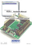
1. INTRODUCTION
1
2. CONFIGURATION AND SPECIFICATIONS
2
3. WIRING
5
4. BUFFER MEMORY ASSIGNMENT
8
5. STATUS INFORMATION
10
6. OPERATION PROCEDURE
12
7. FROM/TO COMMANDS
14
8. REFERENCE
15
1. INTRODUCTION
(1)
Introduction
(3)
The FX-2AD-PT occupies 8 I/O's but does not
affect the addressing of input and output relays. For the purposes of power consumption,
the FX-2AD-PT unit draws 30mA from the 5v rail
of the base unit.
The FX-2AD-PT analog input block amplifies the
input from two platinum temperaturesensors
(PT 100 3 wire, 10052), converts the data into a
12-bit digital reading, and transfers the results
to an FX series programmable controller. Optical coupling is used to ensure that voltage
surges d o not damage other parts of your
equipment.
(2)
UnitSpecifications
(4)
MeasuringUnits
The FX-2AD-PT unit measures temperature in
Centigrade ("C) to a resolution of 0.2 "C, or in
Fahrenheit (OF) to a resolution of 0.36 OF.
CompatibleProgrammableControllers
The FROM/TO instructions are used for transferring data to/from the programmable controller.
Hence, versions 2.0 or subsequent versions of
the FX series programmable controllers (those
with serial no. of 13XXXX or larger) are required.
(5)
StatusInformation
Information concerning the working status of
the FX-2AD-PT including error messages can
be sent to the programmable controller.
(6)
SuitableSensors
3-wire, 100Q PT100 platinum temperature sensors with the following specification are usable:
3850PPM/"C
(JIS C1604-1989)
(DIN 43760)
1
2. CONFIGURATION AND SPECIFICATIONS
(1)
ConfigurationandSpecifications
0
Weight:
Approx. 0.5 kg ( 1 . 1 Ibs)
0
Accessories:
Self-adhesive
labels
special
for
block number identification
M3.5 (0.14")terminal screws
Mounting holes 5.5mm
. l(0.27")dia.
0
f
!
////
Extension cable and
connector
I
i
73 (2.87")
..,.
- -. -,---.-
.
-I
95 (3.74")
I*
-
2
,
__
-
i
140
I 125
('4.92') $51")
-
-__.
-1
I--
35mm (1.38") DIN
rail mounting slot
10 (0.39")
.
I
(2)
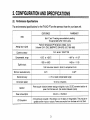
PerformanceSpecifications
The environmental specifications for theFX-PAD-PT are the same as those for your base unit.
FAHRENHEIT
CENTIGRADE
ITEM
Both "C and "F readings are available by reading
the appropriate buffer memory area.
Platinum temperature PT100 sensors (lOOR),3-wire,
2-channel (CH1, CH2), 3850PPMPC (DIN 43760, JIS C1604-1989)
Analog input signal
1mA.sensor:
Current to sensor
I
Compensated. range
Digital output
1
-100°C to +6OO0C
100R PT100
I
-1 48°F to
-1480 to
-1000 to +6000
+ 1112°F
+ 11 120
12-bit conversion stored in 16-bit 2's complement form.
Minimum resolvable temp.
0.36"F
0.2"C
Overall accuracy
+/-1% full scale (compensated range)
Conversion speed
15 ms for 2 channels
Isolation
Photo-coupler isolation between analog and digital circuits. DC/DC converter isolation of
power from the base unit. (No isolation between inputs)
Power consumption
DC24V + / - l o % 50mA
1/0 Occupation
8 I/O points are occupied in the software (i.e. the base unit image table). They may be regarded as either inputs or outputs. Power consumption from the base unit is 5v 30mA.
3
I
2. CONFIGURATION AND SPECIFICATIONS
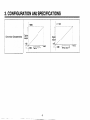
Conversion Characteristics
'1
-loo0
Temp. input '"C
+600
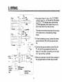
*I The cable of the PT 100 sensor or a twisted
shielded cable should be used for the analog
input cable. This analog input cable should
be wired separately from power lines or any
other lines which may induce noise.
The three wire method improves the accuracy
of the sensors by compensating voltage
drops.
*2 If there is electrical noise, connect theframe
ground terminal (FG) with the ground terminal.
*3 Connect the ground terminal on the FX-2ADPT unit with the grounded terminal on the
base unit. Use class 3 grounding on the base
unit, if grounding is possible.
*4
5
Either an external or the 24V built-in supply in
the programmable controller may be used.
3.WIRING
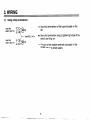
(1)
Usingcrimpterminations
Less than
6.8mm (0.27 in)
Less than
6.8mm (0.27 in)
0
>
Use crimp terminations of the type indicated on the
left.
Secure the termination using a tightening torqueof between 5 and 8 kg * cm.
Use M3.5(0.14in)
0
Wire only to the module terminals discussed in this
manual. Leave all others vacant.
...
3. WIRING
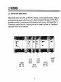
(2)
Use with other special blocks
Other special units or blocks that use FROM-TO commands, such as analog input blocks, analog output blocks and high-speed counter blocks, can be directly connected to the base unit of the FX programmable controller or to the right side of other extension blocks or units. Each special block is
consecutively numbered from 0 to 7 beginning from the one closest to the base unit. A maximum of
eight special blocks can be connected.
I
FX-48MR
X000 - X027
YO00 - YO27
T
T
I
FX-PDA
Special
block 1
FX-4AD
Special
block 0
FX-8 EX
X030 X037
-
7
FX-32ER
X040 - X057
YO30 - YO47
FX-PAD-PT
Special
block 2
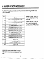
4. BUFFER MEMORY ASSIGNMENT
The FX-2AD-PTanalog input unit transfers data with the programmable controller through
its buffer memory
(16-bit, 32-pointRAM).
BFMS #o, #3, #4, #7, #a, #I I , #12,
#15, #16, #19 to #2a, and #31 cannot be used.
For BFMs without the"*" mark, data
can be readto the programmable
controller using theFROM command.
In BFMs (buffer memory) marked with an
"*", data can be
written from the programmable controller using the
TO command.
4.BUFFER MEMORY ASSIGNMENT
(1) BFMs #9, #10 and #17, #18 store the current value of the input data. This value is in units of
0.1"C or O.l"F, but the resolution is only 0.2"C or 0.36"F.
(2) A number of recently converted readings are averaged to give a smooth read out and the averaged data is stored in BFMs # 5 , #6, and #13, #14.
(3) Number of samples to be averaged are assigned in BFMs #1 and #2. Only the range 1 to 4096 is
valid. Values outside this range are ignored and the defaultvalue of 8 is used.
9
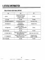
5. STATUS INFORMATION
Status information Buffer Memory BFM #29
When any of b l to b4 is ON
A/D conversion is stopped
for the error channel
Not used
bo: Error
I
b l : Not used
b2: Power source abnormal
b3: Hardware error
Program
b4:
error
1
b5 to b9: Not used
b10: Digital range error
b 11 : Averaging error
1 b12
used
to
15: Not
I
DC 24V power supply failure
AID converter or
other hardware failure
Incorrect installation
or FROM/TO command misused (BFM
data error)
Not used
Digital output / analog input value is outside the specified range.
Averaging is 4097 or more or 0 or less
(default of 8 will be used).
Not used
No error
Not used
Power supply normal
Hardware normal
I
No error
Not used
Digital output value is normal.
I
Averaging is normal.
(between 1 and 4096)
Not used
I
5. STATUS INFORMATION
(1)
Identification Code Buffer Memory
BFM #30
This number for the FX-2AD-PT unit is K2020.
The programmable controller can use this facility in its program to identify the special block before
commencing data transfer from and tothe special block.
11
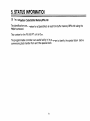
6. OPERATION PROCEDURE
Example Program
In the program shown below, the FX-2AD-PT block occupies the position of special block number 2
(that is the third closest block to the programmable controller). The averaging amount is four. The averaged values in degrees C of input channels CH1 and CH2 are stored respectively in data registers
DO and D l .
Block No.2 BFM X30 * (D2)
Identification code
I-
When (K2020) = (D2), M1=ON. i.e. When
identification code isK 2 0 2 0 , M1 =ON.
Block No.2 BFM #29 + (K4M10)
Transfer the error status to (M25 to M10).
When error is found, M10= ON.
Error found
(K4) + (BFM #1) , (K4)
(BFM #2)
Sampling time is changedto four on
both CH1 and CH2.
+
(BFM #5) +(DO) , (BFM #60) + (01)
Transfer the averaged temperature value
in "Cto the data registers,
12
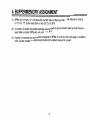
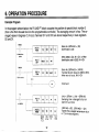
6. OPERATION PROCEDURE
Operation
(1) Standard
(2)
Troubleshooting
Check that the analog input cable, power
line, and extension cable for the FX-2ADPT are all properly connected.
The following LEDs on the front cover of the
FX-2AD-PT can help you troubleshoot the unit.
2.
5v 30mA is supplied from the base or extension units for the FX-2AD-PT. Check
that there is no power overload caused by
this and other special blocks.
This lights up when 5V power is supplied from
the programmable controller. If it is not lit,
check to see if the extension cable is properly
connected.
3.
When DC 24V power is supplied from the
base and extension units of the programmable controller, check that the current is
below the allowable limit (this varies according to the number of extension blocks
connected).
1.
4.
(a) The POWER LED
(b) The 24V LED
This lights up when DC 24V power is supplied
to the FX-2AD-PT. If it is not lit, even if DC
24V 4-10% is being supplied, failure of the
FX-2AD-PT unit may have occured.
(c) The A-D LED
Put the programmable controller into RUN
mode.
This lights up when A/D conversion is proceeding normally. If any of b2 t o b4 of buffer memory e9 (error status) is ON, this LED turns
OFF.
13
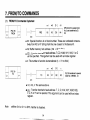
(1)
FROM/TO CommandsExplained
ml
FROM
[.D . ].
n3
K5
DO
K4
BFM #6, X5 in special block
No. 2 are transferredto D l ,
DO,
0
m l : Special function unit or block number. These are numbered consecutively from KO to K7 starting from the one closest to the base unit.
0
m2: Buffer memory head address. (m2
0
=
KO to K31)
P . 1 : Transfer destination head address. T,C,D, KnM, KnY, KnS, V or Z
can be specified. This argument can be used with an index register.
0
FNTco79
K2
m2
n: The number of words to be transferred (n
r
I
TO
=
K1 to K32)
ml
m2
P.1
n
K2
K1
D2
K2
03, D2 transferred to special
block No. 0 BFM#2, #l.
x 11
0
m l , m2, n: The same as above.
destination head address. J, C, D, KnX, KnY, KnM, KnS,
LSregister.
2,: Transfer
K or H can be specified. This argument can be used with an index
Note
.When X 1 0 or X 1 1 is OFF, transfer is disabled.
8. REFERENCE
(1)
System Block Diagram
Power
Confroller
Cammand
information
Write
and
data sfatus
read
Analog Inputs
FX series
CH1
I
CH2
15
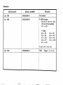
Revisions
EDITION DATE
MANUAL NUMBER
REVISION
Jun. 1991
JY992D28501A
First edition
Apr. 1992
JY992D28501B
P.8 BFM number
#3, #4, #7, #8, # I 1, #12,
#15 and #16 are added.
#11 + #19
In Table
#3 + #5
#5 + #9
#6
# 7 + #13
#9+#17
#11 + #19
P.9 #7, #8
Jan. 1993
.
JY992D28501C
TEXT
+
#4
+
+
#8+
#lo+
#6
#10
#14
#18
#13, #14.
: Pages 1, 3, 7, 8, 13
Under no circumstances will Mitsubishi Electric be liable or responsible for any
consequential damage that may arise as a result
of the installation or use
of this
equipment.
All examples and diagrams shown in this manual are intended only asaid
anto understanding the text, notto guarantee operation. Mitsubishi Electric will acceptno
responsibility for actual useof the product based on these illustrative examples.
Owing to the very great variety in possible applications of this equipment, you
to its suitabilityfor your specific application.
must satisfy yourself as
A MITSUBISHI ELECTRIC CORPORATION
HEAD OFFICE,
HlMEJlWORKS,
JY992D28501C
HI-IB-060-C (9301) (SEN)
M\TSUBISHI DENKI BLDG MARUNOUCHI TOKYO 1W TELEX J24532 CABLE MELCO TOKYO
CHIYODA CHO, HIMEJI, JAPAN
840,
Effective JAN. 1993
69
Specifications are subject
t o change without notice.