1
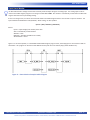
USER’S MANUAL
Revision: 1
HEC-HMI-4-E-R
Divelbiss Corporation
9778 Mt. Gilead Road,
Fredericktown, Ohio 43019
Toll Free: 1-800-245-2327
Web: http://www.divelbiss.com
Email: [email protected]
2010009D.1
Table of Contents
Manual Contents
Getting Started
How to Use this Manual........................................................................ 4
Configuring the HEC-HMI Target in EZ LADDER Toolkit.......................... 5
Loading the HEC-HMI Kernel................................................................. 6
HEC-HMI Basics
Getting to Know the HEC-HMI............................................................... 9
HEC-HMI Assembly / Disassembly....................................................... 11
Wiring to the HEC-HMI....................................................................... 12
Mounting the HEC-HMI....................................................................... 14
HEC-HMI Specifications....................................................................... 15
HEC-HMI Power
Input Power......................................................................................... 16
Input Power Connections.................................................................... 16
Input Power Monitor........................................................................... 17
Communication Ports
Programming Port............................................................................... 18
Modbus, General Purpose Serial Port................................................. 19
OptiCAN Port / J1939 Port................................................................... 21
User Interface
HMI Display......................................................................................... 24
Display Contrast Control...................................................................... 24
Display Backlight Control..................................................................... 24
Programmable LEDs............................................................................. 24
Status LEDs.......................................................................................... 25
Programmable Buttons........................................................................ 25
Display Heater Control......................................................................... 26
Programmable Horn............................................................................ 26
HEC-HMI-4-E-R User’s Manual
Document #: 2010009D.1.pdf
Divelbiss Corporation • 9778 Mt. Gilead Road • Fredericktown, Ohio 43019 • 1-800-245-2327 • www.divelbiss.com
PAGE 1
Table of Contents
Memory
Memory Overview............................................................................... 27
RAM Memory...................................................................................... 27
FLASH Memory.................................................................................... 27
Retentive Memory............................................................................... 28
EEPROM Memory................................................................................ 28
WARNING!!
The HEC-HMI-4, as with other programmable controllers must not be used alone in applications
which could be hazardous to personnel in the event of failure of this device. Precautions
must be taken by the user to provide mechanical and/or electrical safeguards external to this
device. This device is NOT APPROVED for domestic or human medical use.
HEC-HMI-4-E-R User’s Manual
Document #: 2010009D.1.pdf
Divelbiss Corporation • 9778 Mt. Gilead Road • Fredericktown, Ohio 43019 • 1-800-245-2327 • www.divelbiss.com
PAGE 2
Getting Started
This section explains how to read this manual and understand the symbols and information that it contains.
To begin using your HEC HMI, you will need to follow these steps:
• Install EZ LADDER Toolkit if not already installed (not included).
• Configure the HEC HMI in the EZ LADDER Toolkit Project Settings.
• Connect the Input Power and Programming Port.
• Write a ladder diagram program.
• Install the HEC-HMI’s Kernel.
• Download and run the program on the HEC HMI.
Refer to the appropriate sections of this manual for details on the above items.
Getting Started
How to Use this Manual
In this manual, the following conventions are used to distinguish elements of text:
BOLD
italic
SMALL CAPS
Denotes labeling, commands, and literal portions of syntax that must appear exactly as shown.
Used for variables and placeholders that represent the type of text to be entered by the user.
Used to show key sequences or actual buttons, such as OK, where the user clicks the OK button.
In addition, the following symbols appear periodically in the left margin to call the readers attention to specific details in the text:
Warns the reader of a potential danger or hazard associated with certain actions.
Appears when the text contains a tip that is especially useful.
Indicates the text contains information to which the reader should pay particularly close
attention.
All Specifications and Information Subject to Change without Notice
HEC-HMI-4-E-R User’s Manual
Document #: 2010009D.1.pdf
Divelbiss Corporation • 9778 Mt. Gilead Road • Fredericktown, Ohio 43019 • 1-800-245-2327 • www.divelbiss.com
PAGE 4
Getting Started
Configuring the HEC-HMI Target in EZ LADDER Toolkit
Before you can program and use the HEC-HMI, it must be configured as a target within the EZ LADDER Toolkit. For help with installing or using EZ LADDER, please refer to the EZ LADDER User’s Manual.
1. In EZ LADDER, from the File Menu at the top, click PROJECT then SETTINGS. This will open the Project Settings Window.
Select HEC-HMI as the target from the choices. Refer to Figure 1.
Figure 1 - Project Settings Window
2. Click the PROPERTIES button. A new window will open. Select the HEC-HMI-4 Model number of the HEC-HMI from the
drop-down menu. Click OK. This will close the HEC-HMI Properties Window, saving the HEC-HMI-4 as the target for this ladder
diagram project. Refer to Figure 2.
Figure 2 - HEC-HMI Properties Window
3. Click OK to close the Project Settings Window.
HEC-HMI-4-E-R User’s Manual
Document #: 2010009D.1.pdf
Divelbiss Corporation • 9778 Mt. Gilead Road • Fredericktown, Ohio 43019 • 1-800-245-2327 • www.divelbiss.com
PAGE 5
Getting Started
Loading the HEC-HMI Kernel
THE HEC-HMI WILL NOT FUNCTION UNLESS
KERNEL LOADING (This Step) IS COMPLETED.
The kernel is the firmware for the HMI/Controller and to provide greater flexibility and reliability, HEC-HMI shipments are factory
shipped without a kernel installed. If this is a new unit from the factory, it will be necessary to load the kernel before a ladder program can be downloaded. If the kernel is already loaded, this step is not required. To upgrade a kernel, see the EZ LADDER User’s
Manual.
To install the HEC-HMI-4‘s kernel:
1. Verify the target has been configured (see Configuring the HEC-HMI Target in EZ LADDER Toolkit).
2. Connect the Programming cable(s) from the computer to the HEC-HMI. See Programming Port in the HEC-HMI COMPORTs section. Wiring to the Programming Port’s terminal blocks may be required.
3. Create a small one-rung program with a normally open (direct contact) and an output tied together. You may also open a preexisting program for the HEC. EZ LADDER version 1.0.4.4 and later includes a sub-directory (...EZ LADDER\Kernel Install Start Programs\)which has starter programs for each target to load the kernel. Choose GetStarted_HEC-HMI-4.dld.
4. Click the
button to compile the program. The HEC-HMI will only accept compiled EZ LADDER Toolkit programs.
5. Click the
button to change EZ LADDER Toolkit from Edit Mode to Monitor Mode. Monitor Mode is required to communicate, download and monitor programs.
6. Click the
button to connect to the HEC-HMI. A dialog will appear automatically when no kernel is loaded. If this dialog
does not appear, click PROJECT then BOOTLOADER. Refer to Figure 3.
Figure 3 - Bootloader Window
HEC-HMI-4-E-R User’s Manual
Document #: 2010009D.1.pdf
Divelbiss Corporation • 9778 Mt. Gilead Road • Fredericktown, Ohio 43019 • 1-800-245-2327 • www.divelbiss.com
PAGE 6
Getting Started
7. Click the BROWSE button and select the target’s kernel (by partnumber) located by default at C:\Program Files\EZ
Ladder\Kernel\
The following are kernel names and descriptions:
File Name
Description
HEC_HMI.dat
Kernel for HEC-HMI
To be Used on (Partnumber)
HEC-HMI-2, HEC-HMI-4, HEC-HMI-C2100, HEC-HMI-C2150, HEC-HMI-C4100, HEC-HMI-C4150
8. Click the OPEN button to finish the kernel selection. Make sure the correct kernel is chosen.
9. Click the UPDATE TARGET button to install the kernel.
10. A dialog box will appear to show the status of the kernel installation. This could take a several minutes to install.
11. When the status dialog window closes, the installation is complete. The HEC-HMI is ready to use and may be connected to
and programs may be downloaded.
The HEC-HMI Serial Number is factory set and cannot be changed.
HEC-HMI-4-E-R User’s Manual
Document #: 2010009D.1.pdf
Divelbiss Corporation • 9778 Mt. Gilead Road • Fredericktown, Ohio 43019 • 1-800-245-2327 • www.divelbiss.com
PAGE 7
HEC-HMI Basics
This section provides you an overview of the HEC-HMI basics. Some of the basics that are covered are:
Front Panel Features
Wire Entry
Assembly / Disassembly
Internal Connections and Options
HEC-HMI Basics
Getting to Know the HEC-HMI
The HEC-HMI-4 is a powerful HMI, designed to communicate with other devices using Divelbiss OptiCAN or Modbus. The HEC-HMI
boasts a 4x20 backlit LCD display, four navigation buttons (up, down, left, right), Enter and four programmable buttons and four programmable LED indicators that may be used to display warnings, view data or change set points.
The HEC-HMI-4 is housed in a rugged, plastic enclosure and can operate from -40°C to +80° C (using the internal display heater),
making it a valuable tool in harsh environments where temperature extremes are encountered.
Power OK LED
Programmable LEDs
Typical 4 Places
LCD Display Window
Watchdog LED
Navigation Buttons
Programmable Buttons
Typical 4 Places
Mounting Holes x 3
Typical Each Side
Wire Glands
Figure 4 - External Features
HEC-HMI-4-E-R User’s Manual
Document #: 2010009D.1.pdf
Divelbiss Corporation • 9778 Mt. Gilead Road • Fredericktown, Ohio 43019 • 1-800-245-2327 • www.divelbiss.com
PAGE 9
HEC-HMI Basics
The HEC-HMI-4 supports many options and features. Many of the HEC-HMI features are selectable and must configured by setting
switch positions or jumpers internally in the HEC-HMI. To gain access to the internal connections and features, please see the HECHMI Assembly / Disassembly part of this manual section.
The following will get you familiar with the internal design of the HEC-HMI.
SW1
CONFIGURATION
SWITCH
JMP2
SERIAL PORT
VOUT SELECT
TS1,TS4, TS5, TS10,
TS17
SEE DETAIL
JMP1
CAN PORT
TERMINATION
TS12
INPUT POWER
CONNECTION
Wire Gland Entry
Figure 5 - Internal Features
HEC-HMI-4-E-R User’s Manual
Document #: 2010009D.1.pdf
Divelbiss Corporation • 9778 Mt. Gilead Road • Fredericktown, Ohio 43019 • 1-800-245-2327 • www.divelbiss.com
PAGE 10
HEC-HMI Basics
The following diagram provides details for all the HEC-HMI-4 connections for Power, Communications and I/O. In addition, it also
illustrates all the field configuration jumpers and switches with a label of each possible configuration. Each jumper and switch setting is covered in more detail in other sections of this manual.
TS1,TS4, TS5, TS10,
TS17 DETAIL
Figure 6 - Field Selectable Options
HEC-HMI Assembly / Disassembly
All configuration jumpers and terminal blocks are located inside the HEC-HMI enclosure. To configure the unit or to wire the unit,
you must first gain access to the rear of the unit. If mounted to a surface, first un-mount the HEC-HMI to gain access to the rear
(back side) of the unit. Removing the four screws as shown will allow the back of the unit’s enclosure to be removed.
After configuration and wiring is complete, re-assemble the unit in reverse order. Align rear cover, install and tighten four screws as
shown. If the unit was un-mounted, re-mount the unit to the original location.
HEC-HMI-4-E-R User’s Manual
Document #: 2010009D.1.pdf
Divelbiss Corporation • 9778 Mt. Gilead Road • Fredericktown, Ohio 43019 • 1-800-245-2327 • www.divelbiss.com
PAGE 11
HEC-HMI Basics
REMOVE 4 SCREWS
TO DIS-ASSEMBLE
AND GAIN ACCESS TO
INTERNAL WIRING AND
FEATURES
Figure 7 - Assembly / Disassembly
Wiring to the HEC-HMI
Before the HEC-HMI can be wired, it must be dis-assembled first, see the HEC-HMI Assembly / Disassembly of this manual.
All real-world connections on the HEC-HMI are terminal blocks. To allow wire entry into the HEC-HMI enclosure, use the wire gland
that are provided. There will be one or two glands factory installed, based on the actual model number of the HEC-HMI. HEC-HMI
Controllers are shipped with two glands installed, while HEC-HMI without controller is shipped with only one gland factory installed.
To loosen the glands and allow for wire installation, turn the locking nut counter-clockwise. As the nut is repeatedly turned, it will
move outward, releasing the tension on the actual wire entry area. Feed the wires into the glands and route the wires internally in
the HEC-HMI as shown. Refer to Figure 8.
All the provided terminal contact blocks will accept wire from 16 AWG to 26 AWG. For best results, use the size and type of wire
appropriate for the function such as the minimum wire size necessary for the I/O or high quality shielded wire for analog inputs to
promote noise immunity.
HEC-HMI-4-E-R User’s Manual
Document #: 2010009D.1.pdf
Divelbiss Corporation • 9778 Mt. Gilead Road • Fredericktown, Ohio 43019 • 1-800-245-2327 • www.divelbiss.com
PAGE 12
HEC-HMI Basics
ROUTE WIRING AWAY
FROM COMPONENTS
INTO TERMINAL BLOCKS.
WIRE ENTERS
GLAND HERE.
Figure 8 - Typical Internal Wire Routing
HEC-HMI-4-E-R User’s Manual
Document #: 2010009D.1.pdf
Divelbiss Corporation • 9778 Mt. Gilead Road • Fredericktown, Ohio 43019 • 1-800-245-2327 • www.divelbiss.com
PAGE 13
HEC-HMI Basics
Mounting the HEC-HMI
The HEC-HMI is designed to directly mount to any relatively small flat surface or brackets. There are 6 different holes located in the
back mounting flange. The HEC-HMI can be mounted using any combination of these mounting holes and appropriate screws or
bolts as required. Refer to Figure 9.
MOUNTING HOLES ON
EACH SIDE (X2)
MOUNTING HOLES IN
EACH CORNER (X4)
Figure 9 - Mounting & Dimensions
HEC-HMI-4-E-R User’s Manual
Document #: 2010009D.1.pdf
Divelbiss Corporation • 9778 Mt. Gilead Road • Fredericktown, Ohio 43019 • 1-800-245-2327 • www.divelbiss.com
PAGE 14
HEC-HMI Basics
HEC-HMI Specifications
Processor
PLCHIP-M2-25620 (PLC on a Chip™)
User Program RAM
4K
User Program Flash
64K
Retentive Memory
100 Bytes
EEPROM Memory
2792 Bytes
Temperature Range
-40°C to 80°C
RoHS Status
RoHS Compliant
Environmental
Seal Enclosure, Rated NEMA 4X, IP66, UL94V-0
Mounting
Mounts to Panel using provided mounting holes.
Dimensions
5.8” Height x 8.2” Width x 2.4” Depth
Input Voltage
8-32 VDC
Input Current Max.
250mADC
Input Current Typical
110mADC
Display Type
Liquid Crystal Display (LCD)
Display Backlight
Yes, Controlled from Ladder Diagram
Display Heater
Yes, Can be enabled or disabled via Switch.
Display Size
4 Row, 20 Column
Status LED Indicators
Qty 2, Power (PWR) and Watchdog (WD)
Programmable LEDs
Qty 4, Controlled from Ladder Diagram
Programmable Buttons
Qty 9, Up, Down, Left, Right, Center, F1, F2, F3 and F4. Programmable in Ladder Diagram as digital inputs (contacts).
Programming Port
Yes, Terminal Block Connection, RS232
Programming Language
Ladder Diagram using EZ LADDER Toolkit. Program Baud Rate = 57.6K
Multipurpose Serial Port
Yes, Terminal Block Connection, RS232, RS422 or RS485 - Switch Selectable.
CAN Port
Yes, Supports J1939 and Divelbiss OptiCAN
Supported Networks
J1939 and OptiCAN on CAN Port, Modbus Slave on Multipurpose Serial Port.
Wire Entry
Through Gland on bottom of HEC-HMI Enclosure
All Specifications Subject to Change Without Notice.
HEC-HMI-4-E-R User’s Manual
Document #: 2010009D.1.pdf
Divelbiss Corporation • 9778 Mt. Gilead Road • Fredericktown, Ohio 43019 • 1-800-245-2327 • www.divelbiss.com
PAGE 15
HEC-HMI Power
This section explains the connections and power requirements necessary to operate the HEC-HMI. In addition, this section covers
additional information on power related features that may be used in the ladder diagram application software.
Input Power
The HEC-HMI will operate over a 8 to 32 VDC input voltage range. The current required will vary based on actual features used and
environmental conditions. Maximum current is worst case scenario with maximum current in use for each of the HEC-HMI’s features including backlighting, heater, etc.
The input power terminal Block TS12 is rated for 10 Amps and can accept wire size from 26 AWG to 16 AWG.
Maximum Current:
Typical Current (Excluding I/O):
Input Voltage Range:
250mADC
110mADC @ 12VDC, 90mADC @ 24VDC
8-32VDC
Input Power Connections
The input power is connected to the HEC-HMI via the provided terminal blocks as shown in Figure 10. The HEC-HMI back cover
must be removed to connect the input power, see the HEC-HMI Basics section.
PRIMARY INPUT POWER SCHEMATIC
TS12
PRIMARY INPUT POWER WIRING
Figure 10 - Input Power Diagrams
HEC-HMI Power
Input Power Monitor
The HEC-HMI includes a voltage monitor that constantly reads the input voltage as an analog input. This analog input can be accessed in the ladder diagram program as an integer variable labeled AN3. This variable is automatically created when the HEC-HMI
target is selected in the Project Settings Dialog.
As this is an integer value, it must be converted and scaled in the ladder diagram before it can be used as a process variable. The
input should be scaled between 0-40 (0-40VDC). When scaling, use this equation.
InputV = (AN3 / AINScale) x (MaxScale)
Where:
InputV = Input Voltage (real variable) 0.0 to 40.0
AN3 = Automatically created variable
AINScale = 1023
MaxScale = 40.0 (Real Variable to be created)
AIN Resolution = 10-bit
Figure 11 is the same equation, as a EZ LADDER Toolkit ladder diagram program. Note, the Analog input is converted to a REAL for
calculations. This program can be found in HEC-HMI Resource Zip file from our website (http://www.divelbiss.com).
Figure 11 - Power Monitor Example Ladder Diagram
HEC-HMI-4-E-R User’s Manual
Document #: 2010009D.1.pdf
Divelbiss Corporation • 9778 Mt. Gilead Road • Fredericktown, Ohio 43019 • 1-800-245-2327 • www.divelbiss.com
PAGE 17
Communication Ports
This section explains all the communication options and ports for the HEC-HMI. Included will be descriptions of the types of ports,
the typical circuit diagrams required and optional configurations that are available.
All HEC-HMI models are factory shipped with three communication ports; the Programming Port, the OptiCAN/J1939 Port and a
General Purpose/Modbus Slave Port as RS232, RS422 or RS485 (Field Selectable). Details for each port are listed in this section.
Programming Port
The programming port, labeled COM 0 is used to program the HEC-HMI target using the Divelbiss EZ LADDER Toolkit. This connection is an RS232 serial connection and is required to install the Kernel and to download programs to the HEC-HMI. This port is used
for programming only and cannot be used for communication with any other software or device except EZ LADDER Toolkit.
EZ LADDER Toolkit uses the following settings to communicate to the HEC-HMI. Using any other setting will result in communications failures. These parameters are set within EZ LADDER Toolkit (some cannot be changed). You must select the correct COM Port
to which the programming cable is connected to (on the PC). EZ LADDER Toolkit only lists available comports.
Baud Rate: 57600
Parity: None
Data Bits: 8
Stop Bits: 1
Connect your PC to the HEC-HMI via the provided terminal blocks as shown in Figure 12. The HEC-HMI back must be removed to
connect the input power, see the HEC-HMI Basics section. The HEC-HMI-PGM programming cable is required or you may construct
your own cable as shown.
To reduce communication problems when using a USB to Serial Converter, please select a high quality manufacturer. A USB to Serial
Converter that allow direct control over buffering is preferable. Divelbiss Corporation offers a model ideal for this purpose.
PROGRAM PORT CONNECTIONS SCHEMATIC
Figure 12 - Program Port Connections
Communication Ports
Modbus, General Purpose Serial Port
The HEC-HMI provides a second serial port (COM 1) in addition to the programming Port. This port may be used as a general purpose serial port for printing to other devices using the SERIAL_PRINT function in EZ LADDER or it may be used on a Modbus network
as a Modbus Slave.
COM 1 may be used as an RS232, RS422 or RS485. The mode of operation is dependent upon the wiring and the configuration
of the COM 1 settings in the HEC-HMI using the configuration switch SW1. To use the COM 1 multipurpose serial port, connect to
the COM 1 serial port as shown based on the type of configuration (RS232, RS422 or RS485), then configure the switch settings as
shown Figure 13.
Figure 13 - COM 1 Options Switch Settings
Generally, communications between two devices is generally accomplished using RS232 for short distances or RS422 for longer
distances or where additional electrical noise immunity is required due to the environment the device(s) are installed in or near.
RS485 is generally used for applications where multiple drops (more than two devices) are required.
For the HEC-HMI, RS232 only requires 3 wires, RS422 requires 4 wires while RS485 is a two-wire system.
The EZ LADDER Toolkit COM 1 settings are set in the Project Settings dialog. The parameters are set under Serial Print when using
the port to serially print to an external device or they are set under Modbus when using the port as a slave on a Modbus network.
Refer to the EZ LADDER Toolkit User Manual for details on configuring and using Modbus and Serial Print.
COM 1 PORT CONNECTIONS SCHEMATIC - RS232
SW1
Figure 14 - COM1 RS232 Port Connections
HEC-HMI-4-E-R User’s Manual
Document #: 2010009D.1.pdf
Divelbiss Corporation • 9778 Mt. Gilead Road • Fredericktown, Ohio 43019 • 1-800-245-2327 • www.divelbiss.com
PAGE 19
Communication Ports
COM 1 PORT CONNECTIONS SCHEMATIC - RS422
SW1
Figure 15 - COM1 RS422 Port Connections
COM 1 PORT CONNECTIONS SCHEMATIC - RS485
SW1
Figure 16 - COM1 RS485 Port Connections
HEC-HMI-4-E-R User’s Manual
Document #: 2010009D.1.pdf
Divelbiss Corporation • 9778 Mt. Gilead Road • Fredericktown, Ohio 43019 • 1-800-245-2327 • www.divelbiss.com
PAGE 20
Communication Ports
In the event you are connecting the General Purpose Serial Port (COM1) to another smart device that needs to be powered externally, the HEC-HMI provides a power out terminal (labeled +VB). The +VB will supply either 5VDC or the HEC-HMI’s input voltage
(with reverse bias protection) based on the field selectable jumper JMP2. To set this jumper, the unit must be dis-assembled. See
the HEC-HMI Assembly / Disassembly section of this manual.
If the incorrect voltage is selected a connected device could be damaged from over-voltage!
Configure the jumper JMP2 as shown in Figure 17. Removing the jumper completely disconnects all power from the +VB terminal.
Figure 17 - COM1 +VB Power Output Option
OptiCAN Port / J1939 Port
The HEC-HMI can communicate to other devices using it’s on-board CAN bus port. This port supports the J1939 Protocol and the
Divelbiss OptiCAN Protocol.
The CAN bus port may be connected to any J1939 bus, allowing the HEC-HMI to monitor and receive J1939 data broadcasts from
engines, transmissions and more. Refer to the EZ LADDER Manual for 1939 supported features.
The OptiCAN Protocol is a proprietary communication protocol for allowing communications between the HEC-HMI, Controllers and
I/O devices. It is a register based broadcast system. Refer to the EZ LADDER Manual for more details regarding OptiCAN.
Regardless of the bus used, Figures 18 and Figure 19 are typical diagrams for the CAN port.
CAN PORT CONNECTIONS SCHEMATIC
Figure 18 - CAN Port Connections
HEC-HMI-4-E-R User’s Manual
Document #: 2010009D.1.pdf
Divelbiss Corporation • 9778 Mt. Gilead Road • Fredericktown, Ohio 43019 • 1-800-245-2327 • www.divelbiss.com
PAGE 21
Communication Ports
CAN PORT CONNECTIONS WIRING
Figure 19 - Typical CAN Port Wiring
For the CAN bus to operate properly, terminating resistors at each end of the bus are required (typically 120 ohms each). The HECHMI can internally provide the 120 ohm terminating resistor as an option. If the HEC-HMI is physically wired at one of the bus ends,
set the internal JMP1 jumper to enable the terminating resistor as shown in Figure 19. If the HEC-HMI is not physcally wired at one
of the bus ends, set the internal JMP1 jumper to disable the terminating resistor as shown in Figure 20.
Figure 20 - CAN Port Terminating Resistor Option
HEC-HMI-4-E-R User’s Manual
Document #: 2010009D.1.pdf
Divelbiss Corporation • 9778 Mt. Gilead Road • Fredericktown, Ohio 43019 • 1-800-245-2327 • www.divelbiss.com
PAGE 22
User Interface
This section explains the features and basics of the user interface which includes the
LCD display
Backlight Control
Heater Control
Status LEDs
Programmable Buttons
Programmable LEDs
Programmable Horn
User Interface
HMI Display
The HEC-HMI boasts a regular font, 4 line, 20 character
display. This display has a backlight which is controlled in
the ladder diagram project.
To display text and data on the display, the HEC-HMI uses
the LCD_PRINT and LCD_CLEAR function blocks. Using
these blocks to control the display, text and variables can
be displayed and updated as an entire row or can be updated starting with a particular column. The LCD_PRINT function text is formatted per ANSI C printf which provides flexibility. When
printing to the display, the first row (at the top) is always Row 0 and the first column (at the left) is always Column 0.
For details on printing and clearing the display, refer to the EZ LADDER User’s Manual. It provides details on the LCD display printing
and function blocks including formatting control.
Programs with sample displays blocks and menus can be found in the HEC-HMI Resource Zip file from our website (http://www.
divelbiss.com).
The HEC-HMI’s display will function between -40°C and 80°C. Temperatures below 0°C may result in decreased display speed performance while temperatures above 70°C may result in decreased display contrast.
Display Contrast Control
The HEC-HMI’s display contrast is controlled automatically by internal circuits. It will automatically adjust the contrast based on
changes in temperature. The contrast setting is factory set for optimal viewing based generally normal temperature ranges. No
adjustment should be required.
Display Backlight Control
The backlight for the HEC-HMI display is controlled in the ladder diagram project as a coil named BKLGHT. This coil (boolean variable) is automatically created when the HEC-HMI model is selected in the Project Settings. This provides the flexibility of turning off
the backlight to conserve power when operating on batteries. By default, the backlight is turned off. It must be specifically turned
on in the ladder diagram project as shown in Figure 21. An example of this program can be found in the HEC-HMI Resource Zip file
from our website (http://www.divelbiss.com).
Figure 21 - Backlight Control Ladder Diagram
Programmable LEDs
Four programmable LED Indicators (labeled 1 through 4) on the HEC-HMI’s front are provided to aid in the user interface experience. These indicators are controlled by coils in the ladder diagram program. These coils (boolean variables LED1, LED2, LED3
and LED4) are automatically created when the HEC-HMI model is selected in the Project Settings. Each LED indicator is individually
controlled by it’s coil as shown in Figure 22. An example of this program can be found in the HEC-HMI Resource Zip file from our
website (http://www.divelbiss.com).
Figure 22 - Programmble LEDs Control - Ladder Diagram
HEC-HMI-4-E-R User’s Manual
Document #: 2010009D.1.pdf
Divelbiss Corporation • 9778 Mt. Gilead Road • Fredericktown, Ohio 43019 • 1-800-245-2327 • www.divelbiss.com
PAGE 24
User Interface
Status LEDs
Two status LED’s; PWR and WD are provided on the front of the HEC-HMI to alert the status of the
HEC-HMI’s condition. Both are green indicator LEDs.
The PWR Indicator will be illuminated when the input power is within acceptable range (8-32VDC).
If the PWR Indicator is dark, check the input voltage. If the input voltage is within the normal range,
contact Divelbiss Support to have your HEC-HMI serviced.
The WD Indicator identifies the current status of the HEC-HMI. If the WD Indicator is flickering quickly, this indicates that there has
been no kernel loaded on the HEC-HMI. Load the kernel (See Loading the HEC-HMI Kernel section of this manual).
If the WD Indicator is flashing slowly, this indicates the kernel is loaded and the HEC-HMI is waiting for a ladder diagram to be
downloaded (has no program) or that the ladder program is not executing (loaded but not running). To correct this issue, download the program or cause the program to restart by cycling power or clicking the GO button in EZ LADDER Toolkit (when in the Run
mode and connected to the target).
If the WD Indicator is flashing quickly (about 10 times per second), this indicates the kernel and ladder program is loaded and the
ladder program is executing (running).
Programmable Buttons
The HEC-HMI provides a total of Nine programmable buttons. Five of the buttons are placed
to serve as general navigation buttons (Up, Down, Left, Right and Enter (Center)). These are
ideal for scrolling through messages and menus. While these buttons were generally placed
for navigation, they may be used for any purpose in the ladder diagram project. These buttons
are used in the ladder diagram as digital inputs. Contacts (boolean variables) for each button
are automatically created when the HEC-HMI model is selected in the Project Settings. These
variables are PBLT (Left), PBRT (Right), PBUP (Up), PBDN (Down) and PBENT (Center).
The four remaining buttons are placed to serve as general use buttons. Each button may be
programmed and used for any purpose in the ladder diagram project. These buttons are used
in the ladder diagram as digital inputs. Contacts (boolean variables) for each button are automatically created when the HEC-HMI model is selected in the Project Settings. These variables
are F1 (F1), F2 (F2), F3 (F3) and F4 (F4).
Any of the programmable button contacts may be used in the ladder diagram the same as any other contact as shown. Refer to
Figure 23 for a sample of how to use the programmable buttons.
Programs with sample menus using the programmable buttons can be found in the HEC-HMI Resource Zip file from our website
(http://www.divelbiss.com).
Figure 23 - Programmable Buttons - Ladder Diagram
HEC-HMI-4-E-R User’s Manual
Document #: 2010009D.1.pdf
Divelbiss Corporation • 9778 Mt. Gilead Road • Fredericktown, Ohio 43019 • 1-800-245-2327 • www.divelbiss.com
PAGE 25
User Interface
Display Heater Control
To gain the full range of operation on the HEC-HMI, the display has an internal heater. When enabled, the heater will monitor the
temperature and will turn-on when the temperature is at or below 0°C (approximate temperature, typically between 5°C and -5°C).
The heater can be enabled or disabled by an internal switch that is found on SW1. To change the heater setting, the unit must be
dis-assembled. Refer to the HEC-HMI Assembly/Disassembly part of this manual. By default, the heater is factory shipped as enabled, but can be disabled if desired by changing the switch setting as shown in Figure 24.
Figure 24 - Field Selectable Heater On/Off Control
Programmable Horn
A programmable horn is provided for audible feedback situations. The horn is controlled in the ladder diagram project by it’s coil.
The duration the horn is active is controlled only by the horn’s coil. The horn’s frequency is factory set and cannot be changed.
To control the horn, use the horn’s coil (boolean variable BEEP) in the ladder program as shown. The BEEP (boolean variable) for
the horn is automatically created when the HEC-HMI model is selected in the Project Settings. Refer to Figure 25.
Figure 25 - Programmable Horn - Ladder Diagram
HEC-HMI-4-E-R User’s Manual
Document #: 2010009D.1.pdf
Divelbiss Corporation • 9778 Mt. Gilead Road • Fredericktown, Ohio 43019 • 1-800-245-2327 • www.divelbiss.com
PAGE 26
Memory
This section explains the HEC-HMI memory structure and provides details on the amount and types of memory that can be used in
the HEC-HMI.
Memory Overview
The HEC-HMI, as with all other smart devices, requires different types of memory to operate. The HEC-HMI uses the on-board
memory types of the PLC on a Chip™ processor. The PLC on a Chip™ provides both RAM and FLASH memory. These two types of
memory are the basis for all the memory used in the HEC-HMI.
RAM Memory
The HEC-HMI provides 4K bytes (4096 bytes) of RAM. This RAM is the memory the HEC-HMI actually uses to run the ladder diagram. As functions and objects (function blocks, variables, etc.) are added to a ladder diagram, some require bits of RAM to operate while some do not. As the program grows, the amount of unused RAM will decrease.
There is no RAM expansion for the HEC-HMI. In all but few applications, the 4K of RAM will be plenty to complete a program of
thousands of rungs. The determining factor is the mix of variables and functions that use RAM. For example, the Drum_Sequencer
function will use more RAM than many blocks.
To determine how much RAM is used and how much is still available, in EZ LADDER Toolkit, COMPILE the program. The Output
Window will display the amount of RAM that is used and available. If program errors are present, correct the errors and then
COMPILE.. See the example provided in Figure 26.
By default, all variables in a program reside in this RAM and this memory is volatile; meaning if power is lost, the actual contents in
the variables will be lost.
FLASH Memory
The HEC-HMI provides 64K bytes of FLASH. This memory is where the acutal ladder diagram program will reside (is stored) when
loaded into the HEC-HMI. This memory cannot be accessed by the user except as a direct result of the ladder diagram size and being downloaded into the HEC-HMI. As the ladder diagram size grows, so does the amount of FLASH required to store it.
There is no FLASH expansion for the HEC-HMI. In all but few applications, the 64K of FLASH will be plenty to complete a program of
thousands of rungs.
To determine how much FLASH is used and how much is still available, in EZ LADDER Toolkit, COMPILE the program. The Output
Window will display the amount of FLASH that is used and available. If program errors are present, correct the errors and then
COMPILE. See the example provided in Figure 26.
Figure 26 - Memory Usage
Memory
Retentive Memory
As one of the standard features of PLC on a Chip™ and EZ LADDER Toolkit, the HEC-HMI supports the use of Retentive memory.
The HEC-HMI provides 100 bytes of Retentive Memory. This memory actually resides in a PLC on a Chip™ as an EEPROM memory
block. This retentive memory is used to store variables and functions (make variables and functions retentive) whose values or
contents must be maintained when power is lost.
To make variables or functions retentive, a checkbox is provided in the Variable Dialog box (or the Function Properties box). Once
this box is checked, the variable or function is now retentive. When the HEC-HMI detects a power loss, it will automatically store
all these retentive variables (functions) and when power is restored, it will automatically reload all these variables (functions).
As only 100 bytes total is available for Retentive memory. Boolean variables use 2 bytes each, Real and Integer variables use 4
bytes each. Refer to the EZ LADDER Toolkit User’s Manual for more details regarding variables, function and retentive memory.
To determine how much Retentive EEPROM is used and how much is still available, in EZ LADDER Toolkit, COMPILE the program.
The Output Window will display the amount of Retentive EEPROM that is used and available. If program errors are present, correct
the errors and then COMPILE. See the example provided in Figure 26.
EEPROM Memory
As one of the standard features of PLC on a Chip™ and EZ LADDER Toolkit, the HEC-HMI supports the use EEPROM memory that
may be used to store and recall integers in non-volatile memory in the ladder diagram. This can be used to store field adjustable
set points and more.
The HEC-HMI supports 2792 bytes of EEPROM memory. This memory is accessed in the ladder diagram using the EEPROM_READ
and EEPROM_WRITE Function blocks. The same variable type that writes to the EEPROM location should be used to read the EEPROM location. A memory map is recommended for organizing variables stored in EEPROM.
Each EEPROM address is absolute and is one byte in size. Boolean variables fill two bytes while all other variable types fill four
bytes of EEPROM. When writing a boolean to address 0, the actual variable will use addresses 0 and 1 (two bytes). Should you
write an integer variable into address 0, then it would use addresses 0-3. A memory map should be created and used to assign
variable types and addresses prior to coding to ensure that variable size and types are accounted for.
Variable 1 Address - Boolean (2
bytes) uses location 0 and 1.
Variable 2 Address - Integer (4
bytes) uses location 2,3,4 and 5.
Variable 3 Address - Boolean (2
bytes) uses location 6 and 7.
EEPROM ADDRESS LOCATION
Variable & Type
0
1
2
3
4
5
6
7
8
9
Variable 1 (Boolean)
Variable 2 (Integer)
Variable 3 (Boolean)
Figure 27 - EEPROM Memory Locations
EEPROM storage area has a limited number of write cycles; therefore it shouldn’t be used to store data which changes often and
must be re-written often. Writing often to the same location can cause the location to fail.
HEC-HMI-4-E-R User’s Manual
Document #: 2010009D.1.pdf
Divelbiss Corporation • 9778 Mt. Gilead Road • Fredericktown, Ohio 43019 • 1-800-245-2327 • www.divelbiss.com
PAGE 28