1
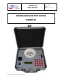
MINIBT 05
USER MANUAL
CODE : MUMOI
REV : 2
DATE: 27 / 06 / 08
PAGE : 1
ADDRESSING AND TEST DEVICE
MINIBT 05
This document consists of 8 pages.
MINIBT 05
USER MANUAL
CODE : MUMOI
REV : 2
DATE: 27 / 06 / 08
PAGE : 2
CONTENTS
I.
DOCUMENT’S EVOLUTION ...................................................................................2
II.
GENERALITY .......................................................................................................3
III.
CHARACTERISTICS.........................................................................................3
IV.
OPERATING INSTRUCTION ..............................................................................4
Main menu ....................................................................................................................4
Manual address coding of an element..........................................................................4
Automatic address coding of an element.....................................................................5
Line verify .....................................................................................................................6
Warnings ......................................................................................................................7
V.
RECOMMENDATIONS.........................................................................................7
Battery install/replace .................................................................................................7
Recommendations for addressing................................................................................8
I.
DOCUMENT’S EVOLUTION
REV
MODIFICATIONS
DATE
1
First release
03 / 07 / 06
MINIBT 05
USER MANUAL
II.
CODE : MUMOI
REV : 2
DATE: 27 / 06 / 08
PAGE : 3
GENERALITY
The “miniBT 05” is an electronic instrument designed to program and verify the DEFNET serial
communication protocol addressable devices, such as fire/smoke detectors, manual call point,
input/output modules and the lines composed by this devices.
It is compatible with devices of series 95 and 05.
“MiniBT 05” appears to the user as a rugged and practical plastic case; by means of its small
outline, the case handle, and the possibility to install a battery to stand-alone from the main
power supply, it results particularly user friendly for field application.
III. CHARACTERISTICS
By opening the case the user access the front panel, which present the following elements:
• The main fused male+female plug (cable not provided),
• The power on switch,
• A sixteen characters over two lines LCD display,
• A sixteen-keys keyboard,
• A couple of spring-connector for fast line connecting,
• A detector base.
Electrical characteristics
Parameter
Main power supply
Main protection
Battery
Battery protection
Autonomy
Main current
Battery current
Value
230Vac 50Hz
Fuse 5x20mm 250V F400mA
Pb 12V 1,9÷2,1Ah
Polyswitch
>6h
< 50mAac standby
< 250mAdc standby
Mechanical characteristics
Parameter
Outline dimensions
Weight
Colour
Protection grade
Value
240 x 223 x 90mm
2,5Kg (with battery)
Black
IP55 (case closed)
Inside the miniBT it takes place an electronic card that controls all the functionalities, and a
battery recess. The battery is kept in charge by the main supply also when the miniBT is
powered off.
MINIBT 05
USER MANUAL
IV.
CODE : MUMOI
REV : 2
DATE: 27 / 06 / 08
PAGE : 4
OPERATING INSTRUCTION
The operations of the miniBT are driven by the user via the keyboard, which has the following
keys: numeric keys 0÷9, direction key ↑ (up) to increment a value, ↓ (down) to decrement, ↵
(enter) to confirm, ← (backspace) to erase the selected numeric character, esc (escape) to go
a step back, menu to go back to the main menu.
The LCD displays operations and variables, note that the blinking block indicates to introduce a
digit.
Main menu
At the power on, the following message appear for a while:
Initialisation
MiniBT-O Vx.y
Then appear the main menu; the bottom line indicates the command achievable simply by
pressing ↵. The options are scrollable (1-2-3-1… o 1-3-2-1…) using the arrows ↑ e ↓:
MiniBT-O Vx.y
1 Manual coding
2 Autom. coding
3 Line verify
The user can enter one of the commands also by pressing the associated number, for example
press 3 to activate the line verify menu.
Manual address coding of an element
This function allows the user to modify the address of an element of which the actual one is
known.
After the command enter (either by pressing 1 form main menu or ↵ when this command is
displayed), the LCD displays:
Enter address
to modify : ▒
The blinking block character
indicates the position of the actual digit; this digit can stand for
units (if no other digit will be introduced), tens (if only one other digit will be introduced) or
hundreds (if other two digits will be introduced) of the variable under editing. In this case the
variable indicates the actual address of the element (detector, MCP, module…) that will be
modified. Note that if none digit is introduced, miniBT will assume the value zero.
Press ← to erase last introduced digit (rectification) or ↵ to confirm the address and go to the
next step; should the element with that address is not present, a “bip” is produced and the
following message will appear for several seconds (after that the visualization goes back to the
request of the address to modify):
MINIBT 05
USER MANUAL
CODE : MUMOI
REV : 2
DATE: 27 / 06 / 08
PAGE : 5
Address xxx
Not found
If the element is present, its LED will blink and the display shows:
New address
tttttt:
▒
The bottom line contains the type of the element and the place to introduce the new address
(cursor); after this value is entered press ↵ to confirm. If the new address is already present on
the line, a “bip” is produced and the following message will appear for several seconds (after
that the visualization goes back to the request of the new address):
Address
already present
If the operation (change the address of an element) completed successfully, this message will
appear until either menu or esc are pressed:
Add. yyy tttttt
address assigned
Note that the LED of the element yyy will blink for the time the message is shown.
Every time is requested to choose an address, if a value out of range is introduced a warning
message is shown for several seconds:
Address out of
range (0-200)
Automatic address coding of an element
This is an effectiveness function useful to address sequentially a lot of elements, especially
during a start-up. Thanks to the miniBT interactivity, the user can assign the address to all the
elements directly on field without accessing the miniBT, which can be connected to any place of
the detection line.
The information exchange between user and miniBT uses the element’s LED and the
opportunity to get the element in alarm.
After the command enter (either by pressing 2 form main menu or ↵ when this command is
displayed), the LCD displays:
Address nbr. 0
searching
At this moment, an element with the address 0 (default address for new elements) is searched
either onto the base or the line; when found, miniBT suggests the first free address subsequent
the last assigned address during the present session and, anyway, not already present; now the
user can see on the display this suggested address or, if he is in the field, it has the information
that a new address is ready to be assigned by means of the element’s LED blinking:
MINIBT 05
USER MANUAL
CODE : MUMOI
REV : 2
DATE: 27 / 06 / 08
PAGE : 6
Add. 0
tttttt
new address :xxx
The new address can be confirmed either by pressing ↵ (if the user is close to miniBT), or by
getting the element in alarm (via an apposite tool for the detectors, pressing MCP, module’s
input activation…). This action inform the miniBT that the new address must be written into the
element, a verify can be made by looking the LCD:
Add. xxx tttttt
address assigned
The same time, the element’s LED will light up for 10 seconds. At the end of this period, the
LED will turn off to indicate the miniBT is gone back to search address 0 for a new operation.
Note that if the address of the element to search is not 0, it is possible, at this moment, to press
↵, the LCD shows:
New address
to search :
▒
Use numeric keys to enter desired value and confirm with ↵.
If the address suggested by the miniBT is not desired, the user can press ↑ to skip it and
display the next one.
Line verify
This function detects how many elements are connected to the miniBT over the line and the
local detector base. Furthermore some informations about the elements are reported to the
user.
After the command enter (either by pressing 3 form main menu or ↵ when this command is
displayed), the LCD displays:
Total addresses
found :
qqq
Where qqq indicates the amount of the elements connected to the miniBT. Note that it can take
a lot of seconds to reach the real amount of elements. Press ↵ to display the information of the
elements starting from lowest address:
Element in standby state:
Add. xxx tttttt
state: normal
Element in fault state:
Element in alarm state:
Dirty optical detector:
Element no more answering:
state: fault
state: alarm
state: dirty
state: no answer
During this visualization, the element’s LED blinks. Use ↑ and ↓ to walk through the elements.
MINIBT 05
USER MANUAL
CODE : MUMOI
REV : 2
DATE: 27 / 06 / 08
PAGE : 7
Warnings
Should the current to either the line or the local base exceed a given value, miniBT would cutoff line power for a lot of time and display the following message:
WARNING !
Short circuit
While stand-alone use, if the battery voltage fall down to an insufficient value, every 15 seconds
a “bip” is generated and this message appears:
WARNING !
Battery low
V.
RECOMMENDATIONS
Battery install/replace
Tools needed: a screwdriver and a 7mm hexagonal wrench.
Turn off miniBT.
Remove main cable.
Close cover; turn the miniBT upside down and then remove the four screws.
Open the cover and remove the metallic frame, the detector base can help in doing it.
Remove the battery bracket by unscrewing the two M4 nuts.
Disconnect battery and remove it (if a battery a present).
Insert a new battery and connect it with the correct polarities: red cable +, black cable .
¾ Lock the battery with the bracket by screwing the two M4 nuts.
¾ Place the metallic frame into the plastic case.
¾ Turn the miniBT upside down and screw the four screws.
¾
¾
¾
¾
¾
¾
¾
WARNING:
This device does not provide any battery circuit
breaker when out of charge. When the battery is
signalled low the user is strongly recommended to
provide either its recharge or replace to avoid a deep
discharge that can damage battery.
MINIBT 05
USER MANUAL
CODE : MUMOI
REV : 2
DATE: 27 / 06 / 08
PAGE : 8
Recommendations for addressing
For a correct use of miniBT and for the best element’s addressing during a fire detection system
commissioning, please follow these indications:
¾ Collect all installation documents (plans, functional descriptions, particular requirements,
…) and the manuals of the whole devices composing the system.
¾ Preview the elements placing to the panel’s lines taking in account installation
requirements, panel’s limitations and power supply limitation.
¾ Set the address for any of the element of the installation.
¾ Either the addressing will be made manually or automatically, stick to any device (and
related base, case, …) the appropriate label indicating the address.
¾ Factory default element’s address is 000.
¾ Do not place to a line two or more elements with the same address (also if 0) because of
the conflicts that will be generated; this will give bad or impossible use of the line.
¾ Before placing addressable elements onto the line, make sure of the electrical
characteristics of the line, especially conductors continuity (also the shield), no shortcircuit and no leakage between conductors.