1
MM4005 4-Axis Motion Controller/Driver
Version 1.09 Firmware
USER’S MANUAL
MM4005
4-Axis Motion Controller/Driver
Warranty
Newport Corporation warrants this product to be free from defects in
material and workmanship for a period of 1 year from the date of shipment.
If found to be defective during the warranty period, the product will either
be repaired or replaced at Newport’s option.
To exercise this warranty, write or call your local Newport representative,
or contact Newport headquarters in Irvine, California. You will be given
prompt assistance and return instructions. Send the instrument, transportation prepaid, to the indicated service facility. Repairs will be made
and the instrument returned, transportation prepaid. Repaired products
are warranted for the balance of the original warranty period, or at least 90
days.
Limitation of Warranty
This warranty does not apply to defects resulting from modification or misuse of any product or part. This warranty also does not apply to fuses, batteries or damage from battery leakage.
This warranty is in lieu of all other warranties, expressed or implied,
including any implied warranty of merchantability or fitness for a particular
use. Newport Corporation shall not be liable for any indirect, special, or
consequential damages.
No part of this manual may be reproduced or copied without the prior written
approval of Newport Corporation.
This manual has been provided for informations only and product specifications are subject to change without notice. Any changes will be reflected
in future printings.
P.A. de Saint Guénault – 3 bis, rue J. Mermoz – BP 189 – 91006 – Evry Cedex – France
Tel.: 33 (0)1.60.91.68.68 – Fax: 33 (0)1.60.91.68.69
EDH0162En1040 – 06/99
ii
MM4005
4-Axis Motion Controller/Driver
Table of Contents
Warranty .................................................................................................................ii
Table of Contents..................................................................................................iii
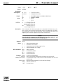
Section 1 — Introduction
1.1
1.2
1.3
1.4
Table of Contents ...................................................................................1.1
Safety Considerations............................................................................1.3
Conventions And Definitions ................................................................1.5
1.2.1 Symbols And Definitions ............................................................1.5
1.2.2 Terminology.................................................................................1.6
General Description ...............................................................................1.7
1.3.1 Features ........................................................................................1.9
1.3.2 Specifications...............................................................................1.9
1.3.3 Modes of Operation ..................................................................1.11
1.3.4 Rear Panel Description .............................................................1.13
1.3.5 Front Panel Description............................................................1.15
1.3.6 Display Configuration ...............................................................1.16
1.3.7 Display Structure.......................................................................1.18
System Setup ........................................................................................1.20
1.4.1 Connecting Motion Devices .....................................................1.21
1.4.2 First Power On ...........................................................................1.21
1.4.3 Verifying Default Devices .........................................................1.22
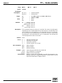
Section 2 — Local Mode
2.1
2.2
2.3
2.4
Table of Contents ...................................................................................2.1
Quick Start .............................................................................................2.3
2.1.1 Motor On .....................................................................................2.3
2.1.2 Home Motion Devices.................................................................2.4
2.1.3 First Jog ........................................................................................2.4
2.1.4 First Move ....................................................................................2.5
Controller Configuration ......................................................................2.7
2.2.1 General Setup ..............................................................................2.7
2.2.2 Axis Setup...................................................................................2.16
Operating In Local Mode .....................................................................2.29
2.3.1 HOME Search .............................................................................2.30
2.3.2 Manual Jog .................................................................................2.30
2.3.3 Zero Display ...............................................................................2.32
2.3.4 Relative Moves...........................................................................2.32
2.3.5 Absolute Moves .........................................................................2.34
2.3.6 Program Execution....................................................................2.35
2.3.7 Axis Infinite Movement.............................................................2.36
2.3.8 Stop Axis Infinite Movement ....................................................2.37
Programming In Local Mode...............................................................2.37
2.4.1 General Concepts ......................................................................2.38
2.4.2 Creating a Program ...................................................................2.38
2.4.3 Modifying a Program.................................................................2.43
iii
EDH0162En1040 – 06/99
MM4005
Table of Contents
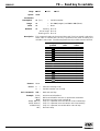
Section 3 — Remote Mode
Table of Contents ...................................................................................3.1
3.1 Remote Interfaces ..................................................................................3.3
3.1.1 RS-232-C Interface........................................................................3.4
3.1.2 IEEE-488 Interface........................................................................3.4
3.2 Softwares.................................................................................................3.4
3.2.1 MOTION Suite ..............................................................................3.5
3.2.2 MOTION Term .............................................................................3.5
3.2.3 MOTION Servo .............................................................................3.6
3.2.4 MOTION Draw..............................................................................3.6
3.2.5 MOTION Prog...............................................................................3.6
3.3 Communication Principles....................................................................3.6
3.3.1 Command Syntax.........................................................................3.7
3.4 Command Summary...............................................................................3.8
3.4.1 Command List by Category........................................................3.8
3.4.2 Command List — Alphabetical................................................3.13
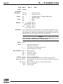
Section 4 — Motion Control Tutorial
Table of Contents ...................................................................................4.1
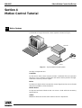
4.1 Motion Systems ......................................................................................4.3
4.2 Specification Definitions........................................................................4.4
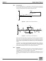
4.2.1 Following Error ............................................................................4.4
4.2.2 Error..............................................................................................4.5
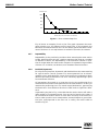
4.2.3 Accuracy.......................................................................................4.5
4.2.4 Local Accuracy ............................................................................4.6
4.2.5 Resolution ....................................................................................4.6
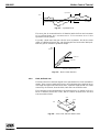
4.2.6 Minimum Incremental Motion ...................................................4.7
4.2.7 Repeatability ................................................................................4.8
4.2.8 Backlash (Hysteresis) .................................................................4.8
4.2.9 Pitch, Roll and Yaw .....................................................................4.9
4.2.10 Wobble........................................................................................4.10
4.2.11 Load Capacity ............................................................................4.10
4.2.12 Maximum Velocity ....................................................................4.11
4.2.13 Minimum Velocity .....................................................................4.11
4.2.14 Velocity Regulation ...................................................................4.12
4.2.15 Maximum Acceleration.............................................................4.12
4.2.16Combined Parameters ...............................................................4.12
4.3 Control Loops .......................................................................................4.13
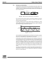
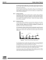
4.3.1 PID Servo Loops ........................................................................4.13
4.3.2 Feed-Forward Loops .................................................................4.15
4.4 Motion Profiles .....................................................................................4.17
4.4.1 Move ...........................................................................................4.17
4.4.2 Jog ...............................................................................................4.18
4.4.3 Home Search ..............................................................................4.18
4.5 Encoders................................................................................................4.21
4.6 Motors ...................................................................................................4.23
4.6.1 Stepper Motors..........................................................................4.24
4.6.2 DC Motors ..................................................................................4.28
4.7 Drivers ...................................................................................................4.29
4.7.1 Stepper Motor Drivers..............................................................4.29
4.7.2 DC Motor Drivers ......................................................................4.31
EDH0162En1040 – 06/99
iv
MM4005
Table of Contents
Section 5 — Trajectory Functions Tutorial
Table of Contents ...................................................................................5.1
5.1 Definition of Terms ................................................................................5.3
5.1.1 Trajectory.....................................................................................5.3
5.1.2 Trajectory Element .....................................................................5.3
5.1.3 Trajectory Vector........................................................................5.3
5.1.4 Vector Velocity ............................................................................5.3
5.1.5 Vector Acceleration ....................................................................5.3
5.2 Trajectory Description and Conventions............................................5.4
5.3 Geometric Conventions.........................................................................5.4
5.4 Defining Trajectory Elements ...............................................................5.5
5.4.1 Defining Lines ..............................................................................5.6
5.4.2 Defining Arcs................................................................................5.6
5.5 Programming a Trajectory....................................................................5.8
5.6 Trajectory Element Parameters ...........................................................5.9
5.7 Trajectory-Specific Commands ..........................................................5.10
5.7.1 Trajectory Setup Commands ...................................................5.10
5.7.2 Trajectory Elements Definition Commands...........................5.10
5.7.3 Reporting Commands ...............................................................5.10
5.7.4 Trajectory Synchronization Commands ................................5.10
5.7.5 Execution of a Trajectory.........................................................5.10
Section 6 — Feature Descriptions Tutorial
Table of Contents ...................................................................................6.1
6.1 Synchronizing Events to Motion ..........................................................6.3
6.1.1 Pulses Synchronized to One Axis..............................................6.3
6.1.2 Pulses Synchronized to a Trajectory........................................6.5
6.1.3 Synchronizing Events to Trajectory Elements ........................6.6
6.1.4 Synchronizing Events to Trajectory Position..........................6.7
6.2 Synchronized Axes (Electronic Gearing) ............................................6.8
6.3 Automatic Program Execution on Power-On: EO Command or from
the Front Panel .......................................................................................6.9
6.4 Continuous Motion: MV Command......................................................6.9
6.5 Automatic Displacement Units Change: SN Command or from the
Front Panel ............................................................................................6.10
6.6 Stage Type Selection: SF Command or from the Front Panel .........6.11
6.7 Reading parameters with “?” ..............................................................6.11
6.8 Error Reporting: TD Command ..........................................................6.13
6.9 Integral Gain Saturation Limit: KS Command ...................................6.13
6.10 Program Editing: EP Command ..........................................................6.13
6.11 Firmware Updates ................................................................................6.13
6.12 Joystick..................................................................................................6.14
6.13 Changing the Display Precision: NP Command or from the Front Panel
................................................................................................................6.15
6.14 Periodic Display Mode: CD Command or from the Front Panel.....6.15
6.15 “$” Parameter........................................................................................6.16
6.16 Asynchronous Acquisition: AQ Command .......................................6.17
6.17 Executing Sub-Routines in a Program: EX Command......................6.18
6.18 Load Communications Mode: CM Command ...................................6.19
6.19 Analog Input/Output: AM, RA, YO, YR Commands ..........................6.19
v
EDH0162En1040 – 06/99
MM4005
Table of Contents
6.20 Default Mode: S-CURVE Profile...........................................................6.20
6.21 Integrator Factor Saturation Level in Position PID Loop Corrector:
KS Command.........................................................................................6.21
Section 7 — Servo Tuning
Table of Contents ...................................................................................7.1
7.1 Servo Tuning Principles ........................................................................7.3
7.1.1 Hardware Requirements ............................................................7.3
7.1.2 Software Requirements ..............................................................7.3
7.2 Tuning Procedures.................................................................................7.4
7.2.1 Axis Oscillation............................................................................7.4
7.2.2 Increasing Performance..............................................................7.5
7.2.3 Points to Remember ...................................................................7.6
Section 8 — Appendices
A
B
C
D
E
F
G
Table of Contents ...................................................................................8.1
Error Messages.......................................................................................8.3
IEEE-488 Link Characteristics ...............................................................8.6
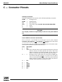
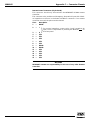
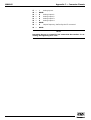
Connector Pinouts .................................................................................8.9
Motion Program Examples..................................................................8.19
Troubleshooting Guide........................................................................8.27
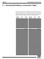
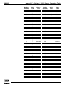
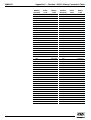
Decimal/ASCII/Binary Conversion Table...........................................8.30
Factory Service .....................................................................................8.33
Section 9 — Index
Command List by Category
Command List — Alphabetical
EDH0162En1040 – 06/99
vi
MM4005
4-Axis Motion Controller/Driver
We declare that the accompanying product, identified with the “ ” mark, meets
all relevant requirements of Directive 89/336/EEC for Electro-Magnetic
Compatibility.
Generic Standard:
Emission
Immunity
EN50081-1
EN50082-2
“Residential, Commercial and Light Industry” and per IEC 1000-4-5 “Surge
Immunity” Standard.
Newport Corporation shall not be liable for damages when using the product:
• Modification of the product.
• Using modified connector, or modified or not supplied cables.
• Connecting this product to non-CE equipments.
• Heavy industrial environment.
vii
EDH0162En1040 – 06/99
MM4005
EDH0162En1040 – 06/99
4-Axis Motion Controller/Driver
viii
Section 1
Introduction
MM4005
4-Axis Motion Controller/Driver
MM4005
4-Axis Motion Controller/Driver
Table of Contents
Section 1 — Introduction
1.1 Safety Considerations............................................................................1.3
1.2 Conventions And Definitions ................................................................1.5
1.2.1 Symbols And Definitions ............................................................1.5
1.2.2 Terminology.................................................................................1.6
Axis................................................................................................1.6
Controller .....................................................................................1.6
Encoder ........................................................................................1.6
Function key.................................................................................1.6
Home (position) ..........................................................................1.6
Home search ................................................................................1.6
Index pulse ...................................................................................1.6
Jog .................................................................................................1.6
MM4005 controller ......................................................................1.6
Motion device ..............................................................................1.6
Move .............................................................................................1.6
Origin ............................................................................................1.6
Origin switch................................................................................1.6
PID .................................................................................................1.6
Remote..........................................................................................1.6
Stage..............................................................................................1.6
1.3 General Description ...............................................................................1.7
1.3.1 Features ........................................................................................1.9
1.3.2 Specifications...............................................................................1.9
Function........................................................................................1.9
Number of motion axes ..............................................................1.9
Trajectory type............................................................................1.9
Motion device compatibility......................................................1.9
CPU type .......................................................................................1.9
DC motor control ........................................................................1.9
Stepper motor control ................................................................1.9
Computer interfaces .................................................................1.10
Utility interface ..........................................................................1.10
Operating modes .......................................................................1.10
Programming .............................................................................1.10
Program memory ......................................................................1.10
Display ........................................................................................1.10
Dimensions.................................................................................1.10
Power requirements .................................................................1.10
Fuses ...........................................................................................1.10
Operating conditions ................................................................1.10
Storage conditions ....................................................................1.10
Weight.........................................................................................1.10
1.1
EDH0162En1040 – 06/99
Table of Contents — Section 1
1.3.3 Modes of Operation ..................................................................1.11
LOCAL Mode ..............................................................................1.11
REMOTE Mode ..........................................................................1.12
Immediate Mode........................................................................1.12
Remote Commands In LOCAL Mode.......................................1.12
1.3.4 Rear Panel Description .............................................................1.13
Axis Modules..............................................................................1.13
GPIO Connector.........................................................................1.13
Power Inhibition Connector.....................................................1.14
Auxiliary Connector ..................................................................1.14
Remote Control Connector ......................................................1.14
RS-232-C Connector ..................................................................1.14
IEEE-488 Connector ...................................................................1.14
Power Switch/Entry Module ....................................................1.14
Ground Post ...............................................................................1.14
1.3.5 Front Panel Description............................................................1.15
Power Stand-by..........................................................................1.15
Motor On/Off .............................................................................1.15
Numeric Keypad ........................................................................1.16
Function Keys / Display ...........................................................1.16
1.3.6 Display Configuration ...............................................................1.16
Display Organization ................................................................1.16
Menu Structure..........................................................................1.17
Common Function Keys ...........................................................1.17
Status Display ............................................................................1.17
1.3.7 Display Structure.......................................................................1.18
MOTOR
OFF
Menus .................................................................1.18
MOTOR
Menu...................................................................1.19
1.4 System Setup ........................................................................................1.20
1.4.1 Connecting Motion Devices .....................................................1.21
1.4.2 First Power On ...........................................................................1.21
1.4.3 Verifying Default Devices .........................................................1.22
ON
EDH0162En1040 – 06/99
1.2
MM4005
4-Axis Motion Controller/Driver
Section 1
Introduction
1.1 Safety Considerations
The following general safety precautions must be observed during all phases of operation of this equipment. Failure to comply with these precautions
or with specific warnings elsewhere in this manual violates safety standards of design, manufacture and intended use of this equipment.
Disconnect or do not plug in the power cord in the following circumstances:
• If the power cord or any other attached cables are frayed or damaged in
any way.
• If the power plug or receptacle is damaged in any way.
• If the unit is exposed to rain, excessive moisture or liquids are spilled on it.
• If the unit has been dropped or the case is damaged.
• If you suspect service or repair is required.
• Whenever you clean the case.
To protect the equipment from damage and avoid hazardous situations, follow these recommendations:
• Do not open the equipment. There are no user serviceable or adjustable
parts inside.
• Do not make any modifications or parts substitutions to the equipment.
• Return the equipment to Newport for any service and repair needs.
• Do not touch, directly or with other objects, live circuits inside the unit.
• Do not operate the unit in an explosive atmosphere.
• Keep all air vents free of dirt and dust.
• Do not block air vents with paper or other objects.
• Keep all liquids away from unit.
• Do not expose equipment to excessive moisture (>85% humidity).
1.3
EDH0162En1040 – 06/99
MM4005
Introduction
WARNING
All attachment plug receptacles in the vicinity of this unit are to be of the
grounding type and properly polarized.
Contact your electrician to check your receptacles.
CAUTION
This product is equipped with a 3-wire grounding type plug. Any interruption of the grounding connection can create an electric shock hazard.
If you are unable to insert the plug into your wall plug receptacle, contact your electrician to perform the necessary alterations to assure that
the green (green-yellow) wire is attached to earth ground.
CAUTION
This product operates with voltages that can be lethal. Pushing objects of
any kind into cabinet slots or holes, or spilling any liquid on the product,
may touch hazardous voltage points or short-circuit parts.
CAUTION
Opening or removing covers will expose you to hazardous voltages.
Refer all servicing internal to this instrument enclosure to qualified service personnel who should observe the following precautions before proceeding:
• Turn power OFF and unplug the unit from its power source;
• Disconnect all cables;
• Remove any jewelry from hands and wrists;
• Use only insulated hand tools;
• Maintain grounding by wearing a wrist strap attached to the instrument chassis.
EDH0162En1040 – 06/99
1.4
MM4005
Introduction
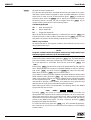
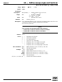
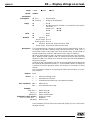
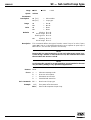
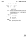
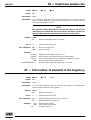
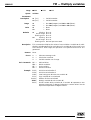
1.2 Conventions and Definitions
1.2.1
Symbols and Definitions
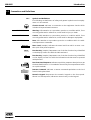
The following are definitions of safety and general symbols used on equipment or in this manual.
Chassis Ground. Indicates a connection to the equipment chassis which
includes all exposed metal structure.
WARNING
Warning. Calls attention to a procedure, practice or condition which, if not
correctly performed or adhered to, could result in injury or death.
CAUTION
Caution. Calls attention to a procedure, practice or condition which, if not
correctly performed or adhered to, could result in damage to equipment.
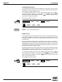
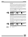
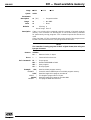
NOTE
Note. Calls attention to a procedure, practice or condition which is considered important to remember.
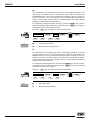
Motor OFF
STATUS
Function Key (sample). Represents one of the four function keys identified
on the display’s menu line with the indicated word.
UP
Function Key (sample). Represents one of the four function keys identified
on the display’s menu line with the indicated word that must be pressed
multiple times.
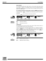
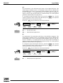
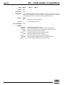
JOG
Axis 1
1 :
2 :
3 :
4 :
HOM E
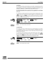
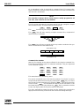
Menu Level (sample). Indicates the menu level from which to start a certain Quick front panel sequence.
1
- 3 . 356
mm
2D e g 4
5
1 2 . 3 4 Axis
2 . 3 4 5 6 mm
n e c 3t e d 7
U n c o n Axis
Se l ec t ac t i on
MANU A L
MO V E
Axis 4
2
3
5
6
8
9
P ROG . .
0
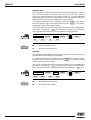
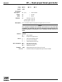
Fast Front Panel Sequence. Indicates a quick key sequence description to get
the described function. It is intended to be used by more experienced users
as a quick reminder.
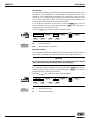
Remote Command. Indicates a remote command equivalent to the local
function being described.
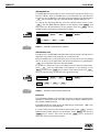
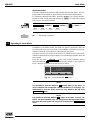
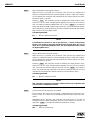
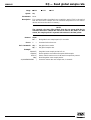
JOG
Axis 1
1
2
3
Axis 2
4
5
6
Axis 3
7
8
9
Axis 4
-
0
.
Numeric Keypad. Represents the numeric keypad on the front panel.
Shown in a fast sequence, indicates a numeric entry on the keypad.
1.5
EDH0162En1040 – 06/99
MM4005
Introduction
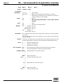
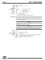
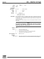
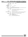
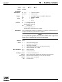
1.2.2
Terminology
The following is a brief description of terms specific to motion control and
this instrument that are used in this manual.
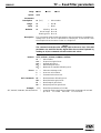
1.2.2.1
Axis
A logical name for a motion device.
1.2.2.2
Controller
In this manual refers mostly to the MM4005 controller/driver.
1.2.2.3
Encoder
Displacement measuring device, term usually used for both linear and
rotary models.
1.2.2.4
Function key
One of the four keys associated with the display; its function is determined
by the current menu.
1.2.2.5
Home (position)
The unique point in space that can be accurately found by an axis, sometimes called origin.
1.2.2.6
Home search
A specific motion routine used to determine the home position.
1.2.2.7
Index pulse
A precision, encoder generated pulse, used in the home search algorithm.
1.2.2.8
Jog
Undetermined length motion initiated manually.
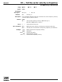
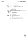
1.2.2.9
MM4005 controller
Refers to the MM4005 integrated controller/driver.
1.2.2.10
Motion device
An electro-mechanical motion device.
1.2.2.11
Move
Motion to a destination initiated manually or remotely.
1.2.2.12
Origin
Used sometimes instead of home.
1.2.2.13
Origin switch
A switch that determines an approximate point in space, used in the home
search routine.
1.2.2.14
PID
Type of closed-loop control algorithm.
1.2.2.15
Remote
In this manual refers to the mode of operation where communication is
performed over a computer interface link.
1.2.2.16
Stage
The most common type of motion device for the MM4005, used interchangeably in this manual for rotary and linear positioners.
EDH0162En1040 – 06/99
1.6
MM4005
Introduction
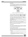
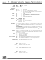
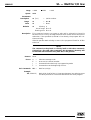
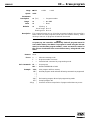
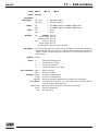
1.3 General Description
The MM4005 is an advanced, stand-alone, integrated motion controller/driver. It can control and drive up to 4 axes of motion, in any stepper and DC
motor combination. The MM4005 controller/driver (also referred to in this
manual as “the controller”) was specifically designed to operate with
Newport’s broad line of motion devices. This way, it significantly increases
the user friendliness and raises the overall motion system performance.
Using other motion devices is possible but not recommended for optimal
system performance.
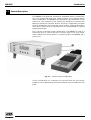
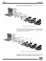
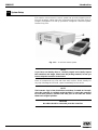
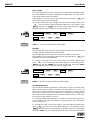
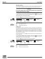
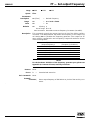
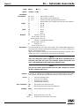
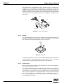
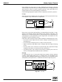
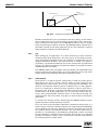
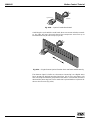
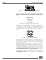
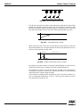
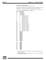
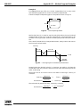
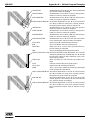
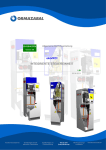
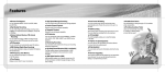
Fig. 1.1 shows a minimal system configuration. The MM4005 is used as a
stand-alone unit to control and drive a motion device. The only components needed are a motion device, a connecting cable, the MM4005 and a
power cord.
Fig. 1.1 — Minimal system configuration.
In this configuration all commands are received from the front panel.
Programs can be generated and executed without using an additional computer.
1.7
EDH0162En1040 – 06/99
MM4005
Introduction
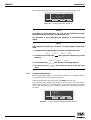
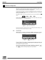
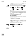
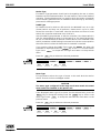
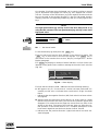
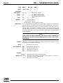
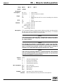
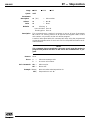
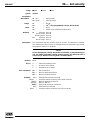
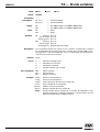
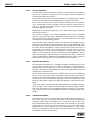
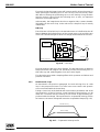
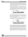
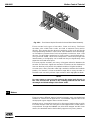
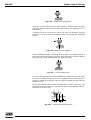
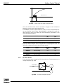
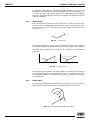
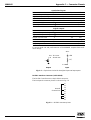
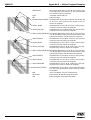
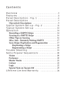
A more common setup is shown in Fig. 1.2. The MM4005 drives multiple
stages and is controlled by a remote computer.
Fig. 1.2 — A common controller setup.
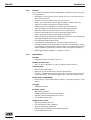
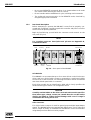
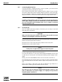
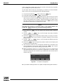
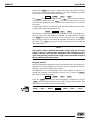
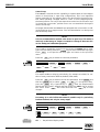
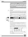
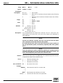
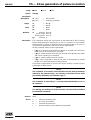
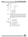
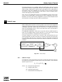
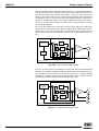
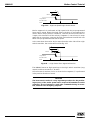
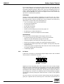
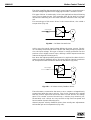
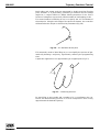
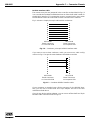
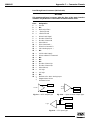
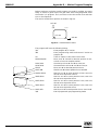
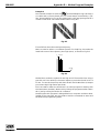
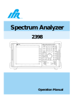
A more complex configuration, shown in Fig. 1.3 , could have up to 4
motion devices, digital and analog I/O signaling for motion synchronization,
remote safety “motor off” switches and be part of a larger multi-axis system, controlled by a remote computer.
To other
Motion Controller
Remote Motor
OFF
Digital/Analog
I/O’s
Fig. 1.3 — A more complex controller configuration.
To explore all capabilities of the MM4005 controller and identify the system
configuration that best fits your application, you will have to read most of
this manual or contact our applications support group for advice.
EDH0162En1040 – 06/99
1.8
MM4005
Introduction
1.3.1
Features
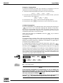
Many advanced features make the MM4005 the preferred choice for precision applications:
• Integrated controller and driver design is more cost effective and a
space saving solution.
• Compact, rack-mountable or bench-top enclosure.
• Allows any combination of motor types (stepper and DC) and sizes.
• Supports closed-loop operation of stepper motors.
• Feed-forward servo algorithm for smooth and precise motion.
• Velocity feedback motor drivers for best motion performance.
• Advanced multi-axis synchronization (linear interpolation).
• Powerful command set for the most demanding applications.
• Motion program storage and management capability.
• Advanced motion programming capabilities with up to 100 nested loops
and complex digital and analog I/O functions.
• User-selectable displacement units.
• User-settable compensation for accuracy and backlash errors.
• Full-featured front panel with bright fluorescent backlit display, numeric/jog keypad, context-sensitive function keys, full motion selection and
control capability and motion program creation and editing capability.
• Multilingual display capability — English or French.
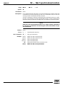
1.3.2
Specifications
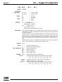
1.3.2.1
Function
• Integrated motion controller and driver.
1.3.2.2
Number of motion axes
• 1 to 4, in any combination or order of stepper and DC motors.
1.3.2.3
Trajectory type
• Non-synchronized motion.
• Multi-axis synchronized motion (linear interpolation).
• S-Curve or Trapezoidal velocity profile for non-synchronized and synchronized motion. The default configuration is S-Curve velocity profile.
1.3.2.4
Motion device compatibility
• Entire family of motorized motion devices, using ether stepper or DC
motors.
1.3.2.5
CPU type
• 5x86/100 Processor.
1.3.2.6
DC motor control
• 16 bit DAC resolution.
• 10 MHz maximum encoder input frequency.
• PID with velocity feed-forward servo loop.
• 0.3 ms digital servo cycle.
1.3.2.7
Stepper motor control
• 1 MHz maximum pulse rate.
• Full, half and mini step capability.
• Open or closed-loop operation.
• PID with velocity feed-forward closed-loop mode.
• 0.3 ms digital servo cycle.
1.9
EDH0162En1040 – 06/99
MM4005
EDH0162En1040 – 06/99
Introduction
1.3.2.8
Computer interfaces
• RS-232-C.
• IEEE-488.
1.3.2.9
Utility interface
• 8-bit opto-coupled digital inputs.
• 8-bit open-collector digital outputs.
• 4 analog inputs, 12-bits resolution programmable input range (0-5 V, 0-10 V,
±5 V, ±10 V).
• External Synchronisation Pulse Output from position acquisition.
• Remote motor off input (interlock).
1.3.2.10
Operating modes
• Local mode: stand-alone operation, executing commands from the front panel.
• Remote mode: execution of commands received over one of the computer interfaces.
• Program execution mode: execution of a stored program, initiated either
remotely or from the front panel, or execution of a program at power-on.
• Trajectory execution.
1.3.2.11
Programming
• Remotely via the computer interface.
• From the front panel.
1.3.2.12
Program memory
• 30 KB (30 760 bytes), non-volatile.
1.3.2.13
Display
• Fluorescent backlit LCD.
• 40 mm x 130 mm, 6 lines by 30 characters.
• Displays position, status, utility menus, program viewing and editing
screens and setup screens.
1.3.2.14
Dimensions
• 5.28 (3U) H x 19 W x 15.6 D in. (134 x 483 x 395 mm).
1.3.2.15
Power requirements
• Power supply with PFC (Power Form Corrector) 90 to 264 V - 50/60 Hz.
• Motors off - 100 VA max.
• Motors on - 570 VA max.
1.3.2.16
Fuses
• AC line only.
Line Voltage Fuse Type: T10A 250 VAC.
1.3.2.17
Operating conditions
• Temperature: 0 to 40 °C.
• Humidity: <85%.
• Altitude: <1000 m.
1.3.2.18
Storage conditions
• Temperature: -15 to 45 °C.
• Humidity: <85%.
• Altitude: <1000 m.
1.3.2.19
Weight
• 18 lb. max. (8 kg max.).
1.10
MM4005
Introduction
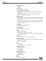
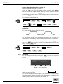
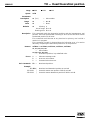
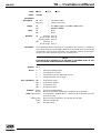
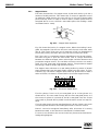
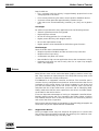
1.3.3
1.3.3.1
Modes of Operation
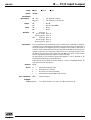
LOCAL Mode
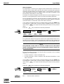
In LOCAL mode, the MM4005 is operated through the keys on the front
panel. The display and function keys allow the selection of menus and
operations that can be performed without using an external computer.
LOCAL MODE
MOTOR
SETUP
OFF
PROGRAM
MOTOR
MOTION
ON
HOME
SEARCH
MANUAL
MOVE
PROGRAM
Execution
Fig. 1.4 — Functions available in LOCAL mode.
Operations that can be performed from the front panel depend on whether
the power to the motors is turned on or off. A motion, for instance, cannot
be performed when the motors are turned off and a general controller
setup should not be done when the motors are on.
SETUP can be activated only from LOCAL mode, Motor Off. In this mode,
the user can set up the general operation of the controller and the parameters specific to every motion axis and motion device.
The PROGRAMMING mode can be activated in LOCAL Mode while motors
are on or off. In programming mode, a motion program can be created or
modified.
MOTION is a general mode of operation in which an axis is commanded to
move. The most complex motions result from executing a program. The
other two cases are when a manual JOG or a point-to-point MOVE is executed.
HOME Search is discussed separately because it is an important procedure
that deserves special attention. In this mode, the controller is executing a
home search algorithm on one or more axes. A home search cycle should
not be interrupted. The controller will exit this mode automatically upon
task completion.
The controller displays a set of heirarchical menus to navigate the various
controller modes. It can be viewed as a “glue logic” between all the other
modes.
1.11
EDH0162En1040 – 06/99
MM4005
Introduction
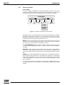
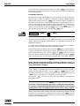
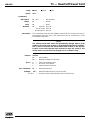
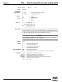
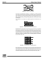
1.3.3.2
REMOTE Mode
To operate in REMOTE mode, the controller must be connected through one
of its interfaces (RS-232-C or IEEE-488) to a computer or terminal. In this
mode, all commands are received remotely and the controller executes them
as directed. The MM4005 command language consists of 129 commands
which are described in chapter 3.
REMOTE MODE
PROGRAM
MOTION
HOME
Search
JOG
MOVE
PROGRAM
Execution
Fig. 1.5 — The functions available in REMOTE mode.
The functions available in REMOTE mode are similar to the ones in LOCAL
mode. The main difference is that the MOTOR OFF / MOTOR ON cases
are handled by the command interpreter so there is no need to distinguish
between them. The controller will refuse to execute motion commands
when the motors are turned off and will set the appropriate error flag.
Another difference between LOCAL and REMOTE is that the SETUP mode
is not available remotely. Some SETUP parameters can be changed but the
controller cannot be placed remotely into a setup mode.
PROGRAMMING mode is enabled and disabled by specific commands. All
valid commands sent in this mode are not executed immediately but stored
as part of a motion program.
MOTION is a general mode of operation in which an axis is commanded to
move. The most complex motions result from program execution. Other
types of motion include manual JOG and a point-to-point MOVE.
HOME Search mode has the same meaning and functionality as in LOCAL
mode. A home search cycle should not be interrupted. The controller will
exit this mode automatically on task completion.
1.3.3.3
Immediate Mode
This is not an operating mode in which the controller can be placed.
Rather, the term merely differentiates the way the controller responds to
remote commands. If a command is not being sent as part of a program, it
is executed “immediately” in immediate mode.
1.3.3.4
Remote Commands In LOCAL Mode
The controller may be operated in LOCAL mode when connected to a
remote computer. The LOCAL mode has many screen and menu combinations and most REMOTE commands are ignored when not received at the
top level menu. For this reason, always keep in mind the following recommendations:
• In LOCAL mode, avoid sending REMOTE commands when not at the top
menu level.
• When not at the LOCAL mode top menu level, restrict the use of remote
commands to those that read information or stop motion.
• Do not send REMOTE commands when in LOCAL PROGRAMMING or
SETUP modes.
EDH0162En1040 – 06/99
1.12
MM4005
Introduction
• Do not send REMOTE commands when in an Intermediate Local mode
(for instance when entering the value of a move).
• Do not interfere with a HOME Search cycle, including read commands.
• The preferred remote operation is the REMOTE mode, obtained by
using the appropriate command.
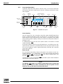
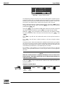
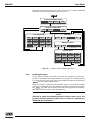
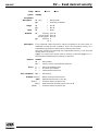
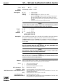
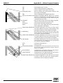
1.3.4
Rear Panel Description
Before attempting to operate the MM4005, it must first be properly connected and configured. Carefully unpack the controller and place it on a flat
surface. Save all packing materials.
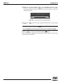
Begin by familiarizing yourself with the connectors and controls on the
rear panel (Fig. 1.6).
NOTE
For complete connector description and pin-outs see Appendix B,
Connector Pin-Outs.
GPIO
Power Switch
RS-232-C
Auxiliary
ATTENTION
Pour une continuité de protection contre les risques de feu, remplacer
uniquement avec des fusibles de type et de caractéristiques spécifiées
Utiliser seulement des fusibles: T6.3A/250V
G
P
I
O
WARNING
R
S
2
3
2
A
U
X
I
L
I
A
R
Y
For continued protection against risk of fire, replace
only with fuse of the specified type and current rating.
Use only fuse: T6.3A/250V
I
E
E
E
4
8
8
P
O
W
E
R
/
I
N
H
I
R
E
M
O
T
E
CAUTION
CAUTION
CAUTION
CAUTION
Do not connect or
disconnect while
power is applied
Do not connect or
disconnect while
power is applied
Do not connect or
disconnect while
power is applied
Do not connect or
disconnect while
power is applied
DC MOTOR
P/N: E1025A
Option #
(UE17CC)
DC MOTOR
P/N: E1025A
Option #
(UE17CC)
DC MOTOR
P/N: E1025A
Option #
(UE17CC)
DC MOTOR
P/N: E1025A
Option #
(UE17CC)
V = 12V, I = 0.22A
V = 12V, I = 0.22A
V = 12V, I = 0.22A
V = 12V, I = 0.22A
5VDC Encod. supply:
5VDC Encod. supply:
5VDC Encod. supply:
5VDC Encod. supply:
C
O
N
T
R
O
L
Axe 1
Axe 2
Axe 3
I
O
Axe 4
ENTREE CA (Sélection automatique)
AC INPUT (Automatic selection)
100-127V 3.6A
200-240V 1.8A
50/60Hz
400VA MAX.
Motor
Interlock
Remote
Control
IEEE-488
Ground Post
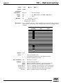
Fig. 1.6 — Rear panel of the MM4005.
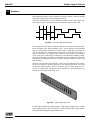
1.3.4.1
Axis Modules
The MM4005 can accommodate up to four motor driver cards. Each motor
driver card has a 25-pin D-Sub connector, mounted on a small panel visible
from the rear of the controller, for attaching the motion device. Uninstalled
axes have a blank panel with no connector.
Each driver module has an identification label which clearly specifies the
model and the type of motor it is configured to drive.
CAUTION
Carefully read the labels on the driver cards and make sure the specifications (motor type, voltage, current, etc.) match those for one the motion
devices you intend to connect. Serious damage could occur if a stage is
connected to the wrong driver card.
1.3.4.2
GPIO Connector
This 37-pin D-Sub connector is used for general purpose digital Input/Output
signals. The MM4005 offers two separate 8-bit digital ports, one for input and
one for output. A variety of commands are available for control and interface
using these ports from within a motion program.
1.13
EDH0162En1040 – 06/99
MM4005
Introduction
1.3.4.3
Power Inhibition Connector
This 9-pin D-Sub connector provides remote motor power interlock capability. One or more external switches can be wired to remotely inhibit the
motor power in a way similar to the MOTOR OFF button on the front
panel. The controller is shipped with a mating 9-pin connector installed
that provides the necessary wiring to enable proper operation without an
external switch.
1.3.4.4
Auxiliary Connector
This 25-pin D-Sub connector has two active lines. One is for motor power
status indication and the other for frequency generator output. The frequency generator is controlled by the motion program and has a frequency
range of 0.01 to 5000 Hz.
1.3.4.5
Remote Control Connector
This 15-pin D-Sub connector provides two functions. The first is similar to
the Power Inhibition connector. The two active pins must be short-circuited
for the motor power to be enabled.
The connector’s second function is to provide inputs for the two analog
ports. These ports are two independent 8 bit analog-to-digital converters.
Programming commands allow the user to read and manipulate the information provided by these ports.
The controller is shipped with a mating 15-pin connector installed that provides the necessary wiring to enable the activation of motor power.
1.3.4.6
RS-232-C Connector
This 9-pin D-Sub connector provides an RS-232-C interface to a host computer or terminal. The port has a three-line configuration using a software
(XON/XOFF) handshake. The pinout enables the use of an off-the-shelf, pinto-pin cable. The port provides internally the necessary jumpers to bypass
the hardware handshake, if needed.
1.3.4.7
IEEE-488 Connector
This is a standard 24-pin IEEE-488 connector.
1.3.4.8
Power Switch/Entry Module
The power entry module include a standard IEC 320 inlet combined with a
line filter, fuse box and main power switch. The main power switch turns
power on and off to the entire unit, including the stand-by circuit.
NOTE
The MM4005 senses the line voltage and automatically switches between
110 V and 220 V operation. The acceptable voltage ranges are 95 to 32 V
or 195 to 263 V at 48 to 63 Hz.
While familiarizing yourself with the rear panel and its components, leave
the main power switch in the OFF position. Always make certain the power
switch is in the OFF position before plugging in the power cord.
1.3.4.9
Ground Post
The ground post provides an additional chassis ground connection when
needed. The MM4005 controller chassis can be externally grounded, in
addition to or instead of the grounding supplied through the AC cord.
EDH0162En1040 – 06/99
1.14
MM4005
Introduction
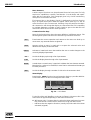
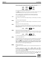
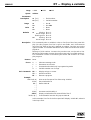
1.3.5
Front Panel Description
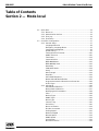
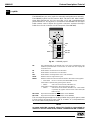
A general view of the front panel is shown in Fig. 1.7. There are three distinct areas, from left to right: power controls, a display and function keys,
and a keypad.
Stand-by
Indicator
On
Indicator
Motion Controller
Motor Off
Switch
2 Adjusting Screws
Contrast Brightness
Display
Keypad
Axis 1 Row
Model MM4005
JOG
I
O
S TA N D - B Y
1
2
3
4
:
:
:
:
0
0
0
0
.
.
.
.
0
0
0
0
0
0
0
0
0
0
0
0
0
0
0
0
mm
mm
mm
mm
Axis 1
MOTOR
HOME
MANUA L
MO V E
P ROG
Axis 2
OFF
Motor On
Indicator
Axis 3
Axis 4
ON
Motor On
Switch
Menu
Line
Function
Keys
Negative Jog
Column
High Speed
Column
Positive Jog
Column
Fig. 1.7 — MM4005 front panel.
1.3.5.1
Power Stand-by
Use this button for your everyday controller power ON/OFF switching.
Power is switched through a relay, not directly as it is through the main
power switch on the rear panel. For this reason, a low power, low voltage
(12V) auxiliary power supply is always on when the main power switch in
the back is ON.
To differentiate from the rear main power switch, this button is called
“Power Stand-by I/O ”.
The power stand-by switch has two LED indicators. A red LED on top, indicates that the controller is powered OFF but the rear power switch is ON.
This is the “Stand-by” mode. A green LED below, indicates the controller
power ON condition.
1.3.5.2
Motor On/Off
For convenience and safety reasons, the power to the motors can be controlled separately. This is done from the front panel through two buttons
labeled MOTOR OFF and MOTOR ON . For easier identification, the
MOTOR OFF button has a red bezel.
A green LED on top of the MOTOR
of the motor Power ON condition.
ON
provides a quick visual indication
NOTE
The MOTOR OFF button is a normally closed switch wired in series with
the two Motor Interlock switch connections on the rear panel. For the
motors to turn on, the entire circuit must be closed.
1.15
EDH0162En1040 – 06/99
MM4005
Introduction
1.3.5.3
Numeric Keypad
On the right hand side of the front panel there is a 12-button numeric keypad. Depending on the mode the controller is in, this keypad can be used
for numerical data entry or controlling the manual JOG mode.
For details on using the keypad for jog control see Section 2, Local Mode.
1.3.5.4
Function Keys / Display
The central part of the front panel is occupied by a large display and four
function keys. The display is a six-line back-lit LCD which shows both menu
and status information.
Below the display are four function keys. Their context-sensitive functions
are always given on the bottom line of the display window.
The contents of the display window are described in detail in Section 2.
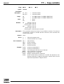
1.3.6
1.3.6.1
Display Configuration
Display Organization
The display has six lines with a maximum of 30 characters each. For better
visibility, the characters are bright on a dark background. Information is
highlighted using dark characters on a bright background.
On the right of the function keys, 2 screws permit to adust the contrast and
the brightness of the display.
CAUTION
Saturation brightness reduces the display lifetime.
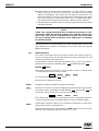
Thebottom line of the display, line number 6, is reserved exclusively for
defining the four function keys.
The next line up, line number 5, is primarily used to display messages, definitions or other helpful information. It generally displays information in
reverse mode.
1
2
3
4
HOM E
:
:
:
:
- 3 .
12 .
2 .
Un c on n
Se l ec t
MANU A L
3
3
3
e
5
4
4
c
a
6
mm
5
Dg .
56
mm
t ed
c t i on
MO V E
P ROG .
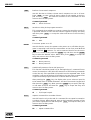
Fig. 1.8 — Typical display contents.
In the above example, line number 6 displays the current function of the
function keys and line number 5 informs us that the controller is idle, waiting for the operator to select an action.
Lines number 1, 2, 3 and 4 identify the axis number and display the current
position of each. Note that in the example, the controller detected that
there is no motion device connected to axis number 4 and displays the
message Unconnected.
When the controller is in some modes ( SETUP , PROG. , etc.), the first
four lines will display specific information while the fifth one will be
reserved for helpful messages.
EDH0162En1040 – 06/99
1.16
MM4005
Introduction
1.3.6.2
Menu Structure
A wide range of functions can be performed from the front panel. To fully
explore its capabilities, carefully read Section 2, Local Mode, and experiment with the controller. This paragraph gives only a brief introductory
description of the menu structure.
The bottom line on the display (line 6) is dedicated to the four function
keys. An option description field will appear above each key if it has an
active function in the current menu. Pressing a key will perform the selected command or will change the display to a new menu level. This capability
to navigate between a number of menu levels to get to the desired command is the basis of the LOCAL mode operation.
1.3.6.3
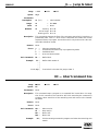
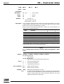
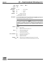
Common Function Keys
Some of the function keys have the same definition in different menus. The
following descriptions list the most common keys and their functions.
QUIT
Terminates the current operation and returns to the menu one level up. In
most cases, any unsaved entries are ignored.
VALID
Appears when an entry is required. It accepts the selected value and
advances the display to the next menu.
MODIFY
Activates a lower-level menu that enables the user to make changes to the
currently displayed parameter.
UP
Scrolls the display up through a list of parameters.
DOWN
Scrolls the display down through a list of parameters.
DELETE
Is used when a numeric entry is required. It deletes the last character entered.
Note that for a value to be modified, it must first be activated and the symbol must precede it.
NEXT
1.3.6.4
Scrolls the display through a number of choices in the same menu level.
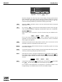
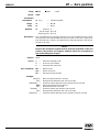
Status Display
Pressing the STATUS function key activates the display to provide additional axis information. It does not change the menu level.
O M
O
+
–M+
HOM E
1
2
3
4
:
:
:
:
- 3 .
12 .
2 .
Un c on n
Se l ec t
MANU A L
3
3
3
e
5
4
4
c
a
6
mm
5
Dg .
56
mm
t ed
c t i on
MO V E
P ROG .
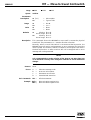
Fig. 1.9 — Axis Status.
To the left of the axis identifiers, as shown in Figure 1.9, there are four characters that can appear depending on the status of each axis:
O Will appear only if a Home Search routine has been performed successfully on that axis. It means that a mechanical origin has been found.
– Indicates that the negative direction (usually left) limit switch has been
activated (tripped).
1.17
EDH0162En1040 – 06/99
MM4005
Introduction
M Appears when the mechanical origin switch is in “high” state. As a stage
moves from one end of travel to the other, you will see this indicator
appear and disappear. This means that the stage has moved from one
side of the switch to the other. The state of this indicator does not affect
the normal operation of the motion device. For a complete description
of the home search algorithm see Section 4, Motion Control Tutorial.
+ Indicates that the positive direction (usually right) limit switch has been
activated (tripped).
NOTE
If both - and + appear, the motion device is either disconnected or a hardware failure exists. On power-up sequence, the controller checks every
axis for this case. If found, it assumes that no motion device is present.
The axis is marked with Unconnected on the display and all commands
for it will be ignored.
At the end of each axis information line an OK is displayed if no error has
been detected. If a problem is detected on one of the axes, the message
ERROR will appear.
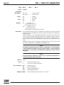
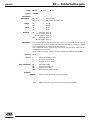
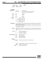
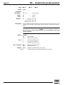
1.3.7
Display Structure
This section describes the most common menus and display functions.
Only local mode menus will be addressed since they represent the vast
majority of the front panel operations.
As described in Section 1.3.3 and illustrated in Fig. 1.4, the local mode is
divided into two sections: MOTOR power OFF and MOTOR power ON .
1.3.7.1
MOTOR
OFF
Menus
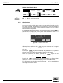
1.3.7.1 MOTOR OFF Menus
When motor power is turned off — the controller “power-on” default mode
— the display function keys are as shown:
STATUS
This is the “top level MOTOR
OFF
PROG.
SETUP
” menu.
Each function is defined as follows:
STATUS
Toggles the display for additional status information.
PROG.
Activates the motion program management and generation environment.
This mode can be activated from both MOTOR OFF and MOTOR ON top
level menus. When selected, the function keys change to:
CREAT.
MODIFY
QUIT
The creation and modification of a program section is addressed extensively in the Programming In Local Mode section of the Local Mode chapter.
SETUP
Is described in detail in Section 2.2, Controller Configuration. A brief introductory description is provided here.
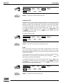
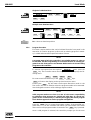
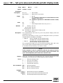
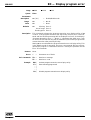
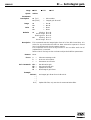
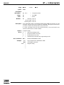
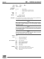
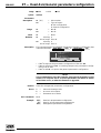
The top level setup menu (after pressing SETUP ) offers the choice of two
different setup categories and looks similar to Fig. 1.10.
EDH0162En1040 – 06/99
1.18
MM4005
Introduction
1
2
3
4
:
:
:
:
U TM 1 0 0 CC 0 . 1
URM8 0 P P
UTM 5 0CC 0 . 1
UZM 1 6 0 PP 0 . 1
S E T UP MEN U
AXES
GEN .
QU I T
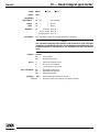
Fig. 1.10 — Top level SETUP menu.
Note the changes in the first four lines on the display. The axs positions have
been replaced by the motion device types the controller thinks are connected to it. This is important because any attempt to first power on the controller should be preceded by a verification of the proper setup.
AXES
Selecting AXES activates a menu to set up each motion device connected
and its parameters.
GEN.
By choosing GEN. you activate the General Setup mode in which the general controller parameters (language, communication ports, etc.) are defined
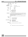
1.3.7.2
MOTOR
ON
Menu
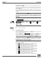
1.3.7.2 MOTOR ON Menu
When motor power is turned on, the four function keys are defined as follows:
HOME
MANUAL
MOVE
PROG.
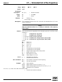
This is the “top level MOTOR ON ” menu. These four choices can be
grouped into three important categories: home search, motion commands
and program management.
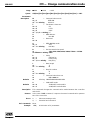
HOME
Activates the home search setup menu in which one or more axes can be
selected to perform a sequential home search cycle.
MANUAL
Is a motion function which allows the user to manually jog each axis using
the numeric keypad.
MOVE
Is a motion function which activates a lower-level menu that offers position
“zeroing”, manual jog and go-to-position functions.
PROG.
Activates the motion program management and generation environment.
This mode can be activated from both MOTOR OFF and MOTOR ON top
level menus. When selected, the next screen shows the following function
choices:
CREAT.
EXEC.
MODIFY
QUIT
Compared to the MOTOR OFF initiated menu, the MOTOR ON menu adds
the EXEC. function which executes stored motion programs.
The creation and modification of programs is covered in detail in the
Programming In Local Mode section of the Local Mode chapter.
1.19
EDH0162En1040 – 06/99
MM4005
Introduction
1.4 System Setup
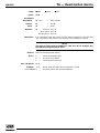
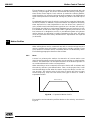
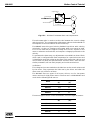
This section covers motion control system set up and preparing use it.
First all necessary cables must be connected and the controller must be
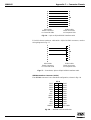
properly configured. This set up procedure configures a minimal system,
similar to Fig. 1.11.
Fig. 1.11 — A minimal control system.
NOTE
If you have not already done so, carefully unpack and visually inspect
the controllers and stages. Please save the packing material, in case you
have to ship the controller in the future.
Place all components on a flat and clear work surface. Check visually for
any sign of damage and if found, report immediately to the carrier.
NOTE
The front two “legs” of the chassis have a tab that, if rotated 90° forward,
place the controller in a slightly angled position. To return the controller
to horizontal position, lift the front side, pull on the tabs and return
them to the original position.
CAUTION
No cables should be connected yet to the controller.
EDH0162En1040 – 06/99
1.20
MM4005
Introduction
1.4.1
Connecting Motion Devices
If you purchased a standard motion control system, you should have
received all necessary hardware to set it up.
First connect the motion device (stage) interface cables. These are 10-ftlong (3-m) cables with 25-pin to 25-pin D-Sub connectors. Insert them gently as you would do with any computer cable, both into the stage and the
appropriate driver card and secure them with the locking thumb-screws.
CAUTION
Carefully read the labels on the driver cards to be sure the specifications
(motor type, voltage, current, etc.) match those for the motion devices
you are connecting. Serious damage could occur if a stage is connected
to the wrong driver card.
1.4.2
First Power On
Once all stages have been properly connected, you are ready to proceed
with the power connection.
CAUTION
Make sure the main power switch on the power entry module is turned
off before connecting the controller to the AC line.
Verify that the main power switch on the rear panel and the stand-by power
switch on the front panel are turned off.
Plug the AC line cord in the power entry module on the rear panel.
Plug the AC line cord in the AC outlet.
NOTE
At this point, no lights should appear on the front panel.
Turn the main power switch on the rear panel on.
The red LED indicator on the front panel marked STAND-BY should come
on and stay on. At this point, the low power stand-by power supply is energized.
Finally, press the red STAND-BY button once to turn the controller on.
The red LED goes off and the green one comes on, the front panel display
turns dark blue and the controller makes a slight ticking sound. This is normal.
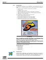
After a short delay, a welcome screen with the Newport logo flashes for a
few seconds, showing you the firmware version in use.
NOTE
Any time you call for technical support, the firmware version is one
piece of information you need to supply. It is displayed every time the
controller power is turned on.
1.21
EDH0162En1040 – 06/99
MM4005
Introduction
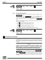
Now, the display shows the main power off menu, similar to Fig. 1.12.
1
2
3
4
:
:
:
:
0 . 00
0 . 00
0 . 00
Un c on n e c
Se l ec t a
S TA TUS
0
mm
0
Deg
0 0 mm
t ed
c t i on
P ROG .
SETUP
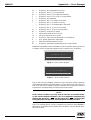
Fig. 1.12 — Display after initial power up.
NOTE
If, instead of a screen similar to Fig. 1.12 you see a different message,
this means that the controller has detected an error.
See Appendix A, Error Messages and Appendix E, Troubleshooting
Guide.
NOTE
If the display looks like Fig. 1.16 but in a wrong language, follow these
steps:
1 Assume the following labeling convention for the function keys:
1
2
2 From the top level MOTOR
sequence:
3 Press function key
OFF
4
menu, press the function keys in this
4
→
2
until the desired language appears.
4 Press function key
menu.
1.4.3
3
4
3
→
3
three times to return to the top level
Verifying Default Devices
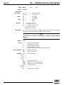
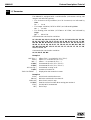
Before powering the motors, verify that the controller is configured for the
actual motion devices it is supposed to drive.
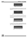
From the main motor off menu, press the SETUP function key.
The top-level setup menu will indicate on the first four lines the type of
motion device each axis is configured for. The display should look similar
to Fig. 1.13. Depending on your system configuration, different models will
be listed.
1
2
3
4
:
:
:
:
U TM 1 0 0 CC 0 . 1
URM8 0 P P
UTM 5 0CC 0 . 1
UZM 1 6 0 PP 0 . 1
S E T UP MEN U
AXES
GEN .
QU I T
Fig. 1.13 — Typical display slowing connected devices.
EDH0162En1040 – 06/99
1.22
MM4005
Introduction
If the components listed match with the actual motion devices installed,
you are ready for the first motion test.
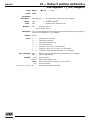
On the other hand, if there is a discrepancy, it must be corrected immediately. In this case, you should perform the following steps:
1 From the main MOTOR OFF menu, select the SETUP key.
2 In the main setup menu press AXES function key.
3 From the next menu press AXIS # function key. This will let you select
which axis you want to modify. (Note the symbol on the first line, in
front of the existing axis number.) Using the numerical keypad, enter
the axis number to be corrected and then press VALID key to accept
the selection and return to the previous screen.
NOTE
Remember that any time a numerical entry on the keypad must be corrected, the DELETE function key erases the last digit entered.
4 Now press the YES key. This enters the product family selection
screen.
5 Use the
or DOWN keys scroll through the product families
UP
until you find the one you need.
6 Press the VALID key to accept the product family currently on the display. The next menu level consists of product models is the chosen
product family.
7 Use the
or DOWN keys to scroll through the different product
UP
models of the chosen family.
8 Press the VALID key to accept the product model on the display and
to advance to the next menu.
9 The next two screens are for changing the default axis parameters, but
do not attempt to do at this point. Press the VALID key to pass
through these screens without making any modifications.
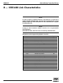
10 When the display returns to a screen similar to Fig. 1.14, observe the
axis specified on the first line and the component on line two. They
should correspond to the selections you made and to the motion device
used on that axis.
P a r ame t e r f o r a x i s # 1
Mo d e l
: UTM 1 0 0CC 0 . 5 HA
AXE#
SELECT
MO D I F Y
QU I T
Fig. 1.14 — Axis/Device Assignment.
11 If you need to modify another axis, repeat all steps starting with number 3.
1.23
EDH0162En1040 – 06/99
MM4005
Introduction
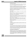
12 When all necessary modifications are completed, from the screen
shown in Fig. 1.14, press the QUIT key. If modifications to any axis
have been made, the next screen will ask if you want to save the
changes (Fig. 1.15).
One
Save
YES
WAR N I NG !
o r seve r a l a xes
b e e n mo d i f i ed !
changes
i n t o
have
E E P ROM ?
NO
Fig. 1.15 — Save screen for axis modifications.
13 Press the
menu.
YES
key to save the changes and return to the main setup
NOTE
If no changes have been made, the screen in Fig. 1.15 will not appear.
14 Press
QUIT
to return to the main MOTOR
OFF
menu.
Now, with all axes configured for the proper motion devices, we are ready
to use the motion devices.
EDH0162En1040 – 06/99
1.24
Section 2
Local Mode
MM4005
4-Axis Motion Controller/Driver
MM4005
4-Axis Motion Controller/Driver
Table of Contents
Section 2 — Mode local
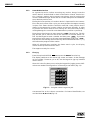
2.1 Quick Start .............................................................................................2.3
2.1.1 Motor On .....................................................................................2.3
2.1.2 Home Motion Devices.................................................................2.4
2.1.3 First Jog ........................................................................................2.4
2.1.4 First Move ....................................................................................2.5
2.2 Controller Configuration ......................................................................2.7
2.2.1 General Setup ..............................................................................2.7
Language Selection .....................................................................2.8
Emergency Language Reset .......................................................2.9
Command Language Set .............................................................2.9
Speed Scaling ...............................................................................2.9
Communication Time-out.........................................................2.10
HOME Time-out .........................................................................2.10
Terminator .................................................................................2.11
Communication .........................................................................2.11
IEEE-488 Address.......................................................................2.12
IEEE-488 SRQ Used ....................................................................2.12
Baud Rate ...................................................................................2.12
XON/XOFF Mode........................................................................2.13
Parity...........................................................................................2.13
Word Length ..............................................................................2.14
Stop Bits .....................................................................................2.14
Axis HOME Sequence................................................................2.14
Master-Slave Mode Definition..................................................2.15
Program Automatical Execution on Power On......................2.16
Profile Type................................................................................2.16
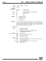
2.2.2 Axis Setup...................................................................................2.16
Axis Number Selection .............................................................2.17
Motion Device Selection...........................................................2.17
Modifying Axis Parameters ......................................................2.18
Units ............................................................................................2.18
Motion Type...............................................................................2.19
HOME Type ................................................................................2.19
Motor Type ................................................................................2.19
Control Loop ..............................................................................2.20
Periodicity ..................................................................................2.20
Motor Increment .......................................................................2.21
Encoder Increment....................................................................2.21
Scaling Speed .............................................................................2.22
Maximum Speed ........................................................................2.22
Manual Speed.............................................................................2.23
HOME Speed ..............................................................................2.23
Acceleration ...............................................................................2.24
Minimum Position .....................................................................2.24
2.1
EDH0162En1040 – 06/99
Table of Contents — Section 2
Maximum Position ....................................................................2.25
HOME Preset..............................................................................2.25
Kp ................................................................................................2.26
Ki .................................................................................................2.26
Kd ................................................................................................2.27
Ks.................................................................................................2.27
Maximum Error..........................................................................2.28
Backlash .....................................................................................2.28
Display Resolution ....................................................................2.29
2.3 Operating In Local Mode .....................................................................2.29
2.3.1 HOME Search .............................................................................2.30
2.3.2 Manual Jog .................................................................................2.30
2.3.3 Zero Display ...............................................................................2.32
2.3.4 Relative Moves...........................................................................2.32
Single Axis Relative Move.........................................................2.33
Multiple Axes Relative Move....................................................2.34
2.3.5 Absolute Moves .........................................................................2.34
Single Axis Absolute Move .......................................................2.35
Multiple Axes Absolute Move ..................................................2.35
2.3.6 Program Execution....................................................................2.35
2.3.7 Axis Infinite Movement.............................................................2.36
2.3.8 Stop Axis Infinite Movement ....................................................2.37
2.4 Programming In Local Mode...............................................................2.37
2.4.1 General Concepts ......................................................................2.38
2.4.2 Creating a Program ...................................................................2.38
Command Line Creation...........................................................2.39
WHILE Loop Creation ...............................................................2.42
2.4.3 Modifying a Program.................................................................2.43
EDH0162En1040 – 06/99
2.2
MM4005
4-Axis Motion Controller/Driver
Section 2
Local Mode
2.1 Quick Start
After reading the Introduction Section you are now prepared to turn the
motors on and command the stages to execute motions. The following
paragraphs will guide you through a quick tour of the LOCAL mode motion
commands.
CAUTION
You should at least read the System Setup Section of the Introduction
before attempting to turn on the controller or the motors. Serious damage could occur if the system is not properly configured.
2.1.1
Motor On
After first turning the controller on as described in the previous section,
you are ready to turn the motors on.
Be sure that the motion devices are placed on a flat surface and that their
full travel will not be obstructed.
CAUTION
Be prepared to quickly turn the motor power off if you observe any
abnormal operation.
Press the MOTOR ON button on the front panel. You may hear a small
relay click inside the controller as the green LED indicator on the button
lights. If no errors are detected, the green LED will stay lit. The display
switches to the top level motor-on menu:
HOME
MANUAL
MOVE
PROG.
The motion system is ready for a command.
2.3
EDH0162En1040 – 06/99
MM4005
Local Mode
2.1.2
Home Motion Devices
As a general practice, before executing any motion, always home the
motion devices. As described in detail in the Motion Control Tutorial section, homing a motion device means executing a special routine that
locates a dedicated origin switch and an encoder index pulse and establishes an absolute position zero.
Finding the home position of a motion device is important for two reasons.
First, after each power off/on cycle, you must position the stage accurately
in space. This means that the controller must find a zero position that is
always in the same point in space, relative to the base. Secondly, in order
to prevent the motion device from running into the limits and possibly
causing damage, the controller must determine its position on power-up.
From the top level motor-on menu press the HOME function key. The display will ask you to select an axis for the execution of a home search routine. Use the keypad to enter a number and then press VALID . If you want
to perform a home search on all axes, leave the default 0 and press VALID .
The axis will start moving, the function keys will be disabled and the display
will indicate the progress of the routine.
When all selected axes complete the home search cycle, the display
returns to the top level motor-on menu.
The stages are ready for a move.
2.1.3
First Jog
From the top level MOTOR
ON
menu press the MANUAL function key.
The display switches to the manual jog screen and menu. As the message
on line number 5 instructs you to do, use the keypad to jog any installed
motion device.
Since this is the first time you are using the keypad for jogging, some clarifications are needed. The keypad is a 3-column by 4-row matrix (Fig. 2.1).
JOG
Axis 1
1
2
3
Axis 2
4
5
6
Axis 3
7
8
9
Axis 4
-
0
.
Fig. 2.1 — Using the numeric keypad to JOG.
Concentrate first on the column convention. For better identification, we
can label them ❶, ❷ and ❸ (Fig. 2.2).
EDH0162En1040 – 06/99
2.4
MM4005
Local Mode
❶
❷
❸
1
2
3
4
5
6
7
8
9
-
0
.
3
Fig. 2.2 — The columns of the numeric keypad
indicate the direction and speed of a JOG.
If a key in column ❶ is pressed, the selected axes will move slowly in the
negative direction.
If a key in column ❸ is pressed, the selected axes will move slowly in the
positive direction.
Column ❷ is used for high-speed jogging. If a key in column ❷ is pressed
simultaneously with one in column ❶ or ❸, the axis will jog at high speed in
the selected direction.
Now, lets take a look at the keypad row convention (Fig. 2.3).
Axis 1
1
2
3
Axis 2
4
5
6
Axis 3
7
8
9
Axis 4
-
0
.
Fig. 2.3 — The rows of the numeric keypad indicate the axis that will JOG.
Each key row controls one axis, as indicated by the label on the left.
To summarize, if you want to jog fast axis number 2 in the positive direction, press simultaneously the keys numbered 5 and 6 .
To exit the manual jog mode press the
2.1.4
QUIT
key.
First Move
From the top level MOTOR ON menu press the
display will offer you the following menu:
MANUAL
RELAT.
ABSOL.
MOVE
function key. The
NEXT
You can start by pressing the ABSOL. key to command an absolute motion.
The next screen will look similar on the top four lines, with the exception of
the symbol in front of the first active axis position. As you recall, this
means that a numerical input is required for the marked value.
Use the keypad to enter a desired destination (absolute position). To correct the entry use the DELETE key. When finished, press the VALID key to
accept the value.
2.5
EDH0162En1040 – 06/99
MM4005
Local Mode
If there is more than one axis connected to the system, the symbol now
jumps to the next axis position displayed. Repeat the desired destination entry
procedure or press VALID until all connected axes have been confirmed and
the following menu appears:
EXEC.
QUIT
Press the EXEC. key and observe the motion devices. They will rapidly
move to the requested destinations and when motion is complete, the display will return to the motion selection menu:
MANUAL
RELAT.
ABSOL.
QUIT
To execute a relative motion, select the RELAT. function key. The same
position entry screen appears as for the absolute motion, with the exception that all position values are zero, rather than the current absolute position. This is because motion is made relative to the current position
instead of absolute home.
Enter desired relative motion values as described earlier. When complete,
the display changes to the following menu:
ALL
QUIT
Pressing the ALL key will start the relative motion on all axes. The difference from the absolute motion is that, when the relative motion on all
axes is finished, the display returns to the same menu. This means that you
can repeat the relative motion again and again by pressing the ALL key.
If you entered relative motion values on multiple axes, but only need to
move one, use the same JOG keypad convention and press a key from column ❶ or ❸ that corresponds to the axis you want to move.
One special note about the keypad in this mode. If you enter a negative
value for a relative move and you press a key in column ❸, the move will be
in the negative direction. If a key in column ❶ is pressed, the move will be
in the positive direction. In other words, pressing a key in column ❶ will
initiate a relative move in the opposite direction than requested.
To exit the relative move mode press the
QUIT
key.
To exit the move mode and return to the top level motor-on menu, press
the QUIT key again.
Now that you know how to JOG and MOVE motion devices, experiment
with front-panel-initiated motions to become familiar with the controller
and the local motion modes.
NOTE
Remember that only motions with destinations inside the software travel
limits are allowed. Any entry outside these limits will be ignored.
EDH0162En1040 – 06/99
2.6
MM4005
Local Mode
2.2 Controller Configuration
Now that you have had the chance to perform some basic motion commands in LOCAL mode more details on the controller’s operation are in
order. The first aspect is the controller configuration.
Though some parameters can also be changed with remote commands, the
primary environment for configuring the MM4005 controller is the SETUP
section of the LOCAL mode.
The SETUP mode can only be initiated from the top level MOTOR
menu:
STATUS
PROG.
OFF
SETUP
Pressing the SETUP function key will enter the setup mode and display
the main setup screen and menu (Fig. 2.4).
1
2
3
4
:
:
:
:
U TM 1 0 0 CC 0 . 1
URM8 0 P P
UTM 5 0CC 0 . 1
UZM 1 6 0 PP 0 . 1
S E T UP MEN U
AXES
GEN .
QU I T
Fig. 2.4 — Typical main setup menu.
There are two types of setup functions: Axis Setup and General Setup. The
following sections will describe both in detail.
2.2.1
General Setup
General Setup is entered by pressing the GEN. function key in the top
level setup menu. The display will change to the one illustrated in Fig. 2.5.
GEN ERA L S ET UP
Language
:
ENGL I S H
Se l e c t d i sp l ay l anguage
UP
D OW N
MOD I F Y
QU I T
Fig. 2.5 —
GEN.
setup menu.
The top display line (number 1) indicates the setup mode (or level). Line
number 3 displays one parameter at a time and its current value. Line number 5 displays an operator prompt.
The function key definition line (number 6) displays a menu that is common for most setup screens at this level. The first two functions,
UP
and DOWN , perform scrolling through a list of parameters.
2.7
EDH0162En1040 – 06/99
MM4005
Local Mode
Pressing the MODIFY key enters a lower level menu that allows modification of the currently displayed parameter. If the value needed is provided
from a short list, the new menu looks like this:
CHANGE
QUIT
VALID
The CHANGE key scrolls through the list, QUIT exits this level without
recording any modification and VALID also returns to the previous screen
(level) but the displayed value is stored as the new entry for the selected
parameter.
If a parameter requires a numerical value, the menu level that allows modifications will have the following choices:
DELETE
QUIT
VALID
The numerical value displayed will have a sign in front, indicating that a
numerical entry from the keypad is expected. For simple editing, pressing
the DELETE key erases the last digit of the numerical entry. The VALID
key accepts the value for the selected parameter and returns to the previous menu. The QUIT key returns to the previous menu without keeping
any modifications.
NOTE
This manual contains detailed descriptions, mostly with the first time
reader in mind. To help the more experienced user looking for a quick
memory refresher, each operation description is also accompanied by a
quick front panel key sequence and, if appropriate, the remote command
that accomplishes the same function.
2.2.1.1
Language Selection
The first parameter displayed from the General Setup list is the display language. This sets the language the controller uses to communicate with the
operator, especially through the front panel.
The MM4005 can use two languages at this time: English and French. To
change the language, from the display shown in Fig. 2.5 press the MODIFY
key. The new menu displayed is
CHANGE
QUIT
VALID
Press the CHANGE key until the desired language is displayed. Press the
VALID key to accept the selection and return to the previous menu. The
display will now use the new selected language.
JOG
Axis 1
1 :
2 :
3 :
4 :
HOM E
EDH0162En1040 – 06/99
1
- 3 . 356
mm
2D e g 4
1 2 . 3 4 Axis
5
2 . 3 4 5 6 mm
n e c 3t e d 7
U n c o n Axis
Se l ec t ac t i on
MANU A L
MO V E
Axis 4
2
3
5
6
8
9
SETUP →
GEN.
P ROG . .
0
2.8
→ MODIFY → CHANGE → VALID →
QUIT
→
QUIT
MM4005
Local Mode
2.2.1.2
Emergency Language Reset
In case the controller has been set to operate in a language you do not
understand, use the following procedure to reset the controller:
1 Assume the following labeling convention for the function keys:
1
2
3
4
2 From the top level motor-off menu (power-on default screen), press the
function keys in this sequence:
→
4
3 Press function key
4 Press function key
2.2.1.3
2
4
3
→
3
until the desired language appears.
three times to return to the top level menu.
Command Language Set
The second parameter in the General Setup menu (selected by pressing the
key once) is the Command Language Set, labeled as Controller.
UP
This is the only parameter that you must not change. It selects the command set the controller will respond to. The selection exists only to assure
compatibility with future controller models.
Always leave the setting on STANDARD. Press the
to the next parameter.
2.2.1.4
UP
key to advance
Speed Scaling
The Speed Scaling parameter offers a feature not present in many high-end
controllers. It allows an user to execute a motion program at a reduced
speed to more easily observe its operation. This feature is a great help in
troubleshooting complex programs.
To change speed scaling from the General Setup menu, press the
UP
key until the speed scaling parameter is selected in the display. To change
the value, press the MODIFY key. The display will prompt you to change the
existing value by preceding it with the sign. Use the keypad to enter the
desired % value. The maximum value is 100% , meaning that the controller
will run with the actual programmed velocities. To reduce the program execution speed to half of the programmed value, enter 50. This means that all
velocities in a program will be reduced to 50%.
JOG
Axis 1
1 :
2 :
3 :
4 :
HOM E
1
- 3 . 356
mm
2D e g 4
5
1 2 . 3 4 Axis
2 . 3 4 5 6 mm
n e c 3t e d 7
U n c o n Axis
Se l ec t ac t i on
MANU A L
MO V E
Axis 4
2
3
5
6
8
9
Motor OFF
→ SETUP →
GEN.
→
UP
→ MODIFY →
P ROG . .
0
JOG
Axis 1
1
2
3
Axis 2
4
5
6
Axis 3
7
8
9
Axis 4
-
0
.
→ VALID →
QUIT
→
QUIT
SD — Set scaling speed.
NOTE
In the following paragraphs it is assumed that you need to modify only
the mentioned parameter. For that reason, the key sequence description
starts from the General Setup menu and the quick key sequence starts
and stops at the top level MOTOR OFF menu.
If you need to modify more than one parameter, advance through the list
with the
key, without returning each time to the top menu.
UP
2.9
EDH0162En1040 – 06/99
MM4005
Local Mode
2.2.1.5
Communication Time-out
This parameter represents the time duration the controller will wait when
expecting an input. It is a general communication parameter that applies to
both RS-232-C and IEEE-488 interfaces.
UP
To change the existing value, from the General Setup menu, press
until the parameter appears on the display. Press MODIFY and then enter
the desired value on the keypad. Press the VALID key to accept the entry
and return to the previous menu.
The default value is 1 seconds.
JOG
Axis 1
1 :
2 :
3 :
4 :
HOM E
1
- 3 . 356
mm
2D e g 4
5
1 2 . 3 4 Axis
2 . 3 4 5 6 mm
U n c o n Axis
n e c 3t e d 7
Se l ec t ac t i on
MANU A L
MO V E
Axis 4
2
3
5
6
8
9
Motor OFF
→ SETUP →
GEN.
→
UP
→ MODIFY →
P ROG . .
0
JOG
Axis 1
1
2
3
Axis 2
4
5
6
Axis 3
7
8
9
Axis 4
-
0
.
→ VALID →
QUIT
→
QUIT
CMOxx — Set communication setup.
2.2.1.6
HOME Time-out
This parameter sets the time duration for which the controller will wait for
each axis to complete a home search routine. Since the controller cannot be
interrupted during a home search, this parameter provides a time-out in case
of malfunction.
Use this parameter with discretion. A small value will cause the controller to
falsely report an error when the stage starts a home search cycle from an
extreme distance and does not have enough time to complete it. A large value
prevents the controller from detecting a real problem, when the home search
cycle takes an excessive amount of time.
An ideal home time-out value is about 20% over the time it takes the slowest
stage installed to perform a home search. The longest time is usually when
the stage starts from the farthest point away from the origin switch.
To change the existing value, from the General Setup menu, press
UP
until the parameter appears on the display. Press MODIFY and then enter the
desired value on the keypad. Press the VALID key to accept the entry and
return to the previous menu.
The default value is 90 seconds.
JOG
Axis 1
1 :
2 :
3 :
4 :
HOM E
1
- 3 . 356
mm
2D e g 4
5
1 2 . 3 4 Axis
2 . 3 4 5 6 mm
U n c o n Axis
n e c 3t e d 7
Se l ec t ac t i on
MANU A L
MO V E
Axis 4
2
3
5
6
8
9
Motor OFF
→ SETUP →
GEN.
P ROG . .
0
JOG
EDH0162En1040 – 06/99
Axis 1
1
2
3
Axis 2
4
5
6
Axis 3
7
8
9
Axis 4
-
0
.
→ VALID →
2.10
QUIT
→
QUIT
→
UP
→ MODIFY →
MM4005
Local Mode
2.2.1.7
Terminator
This parameter defines the terminator to be used in communication with a
host computer or a terminal. As described in the Remote Mode section, the
controller responds to command lines, not characters. In order for a command to be acted upon, it must be followed by the terminator.
The MM4005 controller offers a choice of four command line terminators
which are combinations of line-feeds and carriage-returns: LF, CR, CR/LF
and LF/CR.
To change the existing selection from the General Setup menu, press
until the Terminator parameter appears on the display. Press
UP
MODIFY and then the CHANGE key until the desired terminator is selected.
Press the VALID key to accept the entry and return to the previous menu.
The factory default terminator is LF.
JOG
Axis 1
1 :
2 :
3 :
4 :
HOM E
1
- 3 . 356
mm
2D e g 4
5
1 2 . 3 4 Axis
2 . 3 4 5 6 mm
U n c o n Axis
n e c 3t e d 7
Se l ec t ac t i on
MANU A L
MO V E
Axis 4
2
3
5
6
8
9
Motor OFF
→ SETUP →
GEN.
→
UP
→ MODIFY →
P ROG . .
0
CHANGE →
VALID
→
QUIT
→
QUIT
CMTxx — Set communication terminator.
2.2.1.8
Communication
This setting selects the communication port to be used with a host computer. The MM4005 controller can use either the RS-232 or IEEE-488 interface but
only one at a time. The selection can be made only through this setup.
Default mode is RS-232-C.
To change the existing selection from the General Setup menu, press
UP
until the Communication parameter appears on the display. Press MODIFY
and then the CHANGE key to select a new communication port. Press the
VALID key to accept the entry and return to the previous menu.
JOG
Axis 1
1 :
2 :
3 :
4 :
HOM E
1
- 3 . 356
mm
2D e g 4
5
1 2 . 3 4 Axis
2 . 3 4 5 6 mm
U n c o n Axis
n e c 3t e d 7
Se l ec t ac t i on
MANU A L
MO V E
Axis 4
2
3
5
6
8
9
Motor OFF
→ SETUP →
GEN.
→
UP
→ MODIFY →
P ROG . .
0
CHANGE →
VALID
→
QUIT
→
QUIT
CMMxx — Set communication mode.
2.11
EDH0162En1040 – 06/99
MM4005
Local Mode
2.2.1.9
IEEE-488 Address
The IEEE-488 standard requires each connected instrument (device) to
have an address. Even if the IEEE port is not selected, the controller will
prompt you for an address. If not used, ignore the selection by pressing the
key and advancing to the next parameter. Default address is 2.
UP
To change the existing address from the General Setup menu, press
until the IEEE Address appears on the display. Press MODIFY and
UP
then enter the desired address on the keypad. Press the VALID key to
accept the entry and return to the previous menu.
JOG
Axis 1
1 :
2 :
3 :
4 :
HOM E
1
- 3 . 356
mm
2D e g 4
5
1 2 . 3 4 Axis
2 . 3 4 5 6 mm
U n c o n Axis
n e c 3t e d 7
Se l ec t ac t i on
MANU A L
MO V E
Axis 4
2
3
5
6
8
9
Motor OFF
→ SETUP →
GEN.
→
UP
→ MODIFY →
P ROG . .
0
JOG
Axis 1
1
2
3
Axis 2
4
5
6
Axis 3
7
8
9
Axis 4
-
0
.
→ VALID →
QUIT
→
QUIT
CMAxx — Set IEEE communication address.
2.2.1.10
IEEE-488 SRQ Used
The SRQ line is an IEEE-488 handshake that ensures proper transmission of
large files (trace data, large programs, etc.) Default is NO.
Even if the IEEE port is not selected for use, the controller will still prompt
you for an entry. If not applicable, just ignore the selection by pressing the
key and advancing to the next parameter.
UP
To enable or disable the use of the SRQ from the General Setup menu,
press
until the IEEE SRQ Used appears on the display. Press
UP
MODIFY and then the CHANGE key to select a new setting. Press the VALID
key to accept the entry and return to the previous menu.
JOG
Axis 1
1 :
2 :
3 :
4 :
HOM E
1
- 3 . 356
mm
2D e g 4
5
1 2 . 3 4 Axis
2 . 3 4 5 6 mm
n e c 3t e d 7
U n c o n Axis
Se l ec t ac t i on
MANU A L
MO V E
Axis 4
2
3
5
6
8
9
Motor OFF
→ SETUP →
GEN.
→
UP
→ MODIFY →
P ROG . .
0
CHANGE →
VALID
→
QUIT
→
QUIT
CMQxx — Set IEEE communication SRQ mode.
2.2.1.11
Baud Rate
This parameter applies to the RS-232-C interface. It sets the communication
speed to be used on this port. The valid range is from 1200 to 115200. The factory default is 9600 baud rate.
If the IEEE interface is used, ignore the selection by pressing the
and advancing to the next parameter.
UP
key
To set the baud rate from the General Setup menu, press
until the
UP
Baud Rate parameter appears on the display. Press MODIFY and then the
CHANGE key to select a new value. Press the VALID key to accept the
entry and return to the previous menu.
EDH0162En1040 – 06/99
2.12
MM4005
Local Mode
JOG
Axis 1
1 :
2 :
3 :
4 :
HOM E
1
- 3 . 356
mm
2D e g 4
5
1 2 . 3 4 Axis
2 . 3 4 5 6 mm
U n c o n Axis
n e c 3t e d 7
Se l ec t ac t i on
MANU A L
MO V E
Axis 4
2
3
5
6
8
9
Motor OFF
→ SETUP →
GEN.
→
UP
→ MODIFY →
P ROG . .
0
CHANGE →
VALID
→
QUIT
→
QUIT
CMBxx — Set serial communication baud rate.
2.2.1.12
XON/XOFF Mode
XON/XOFF mode synchronizes work between the transmitter and the
receiver. In this mode, XON and XOFF characters are sont automatically
generated (XOFF if the receipt buffer is almost full and risks to be erased,
XON if the receipt buffer is sufficiently emptied to receive new characters).
To change the setting, from the General Setup menu, press
until
UP
the XON/XOFF Mode appears on the display. Press MODIFY and then
the CHANGE key to select YES. Press the VALID key to accept the entry and
return to the previous menu.
The factory default is NO.
JOG
Axis 1
1 :
2 :
3 :
4 :
HOM E
1
- 3 . 356
mm
2D e g 4
5
1 2 . 3 4 Axis
2 . 3 4 5 6 mm
n e c 3t e d 7
U n c o n Axis
Se l ec t ac t i on
MANU A L
MO V E
Axis 4
2
3
5
6
8
9
Motor OFF
→ SETUP →
GEN.
→
UP
→ MODIFY →
P ROG . .
0
CHANGE →
VALID
→
QUIT
→
QUIT
CMXxx — Set serial communication XON/XOFF mode.
2.2.1.13
Parity
Parity must be set correctly for the RS-232-C communication to work properly. As the standard suggests, when a word length of less than 8 is used,
the parity bit can be set to Odd or Even. Both communicating devices must
use the same setting.
The possible settings are Odd, Even and None. The factory default is None.
If the RS-232-C is not used, ignore the selection by pressing the
and advancing to the next parameter.
UP
key
To change the setting, from the General Setup menu, press
until
UP
the Parity parameter appears on the display. Press MODIFY and then
the CHANGE key to select a new parity. Press the VALID key to accept the
entry and return to the previous menu.
JOG
Axis 1
1 :
2 :
3 :
4 :
HOM E
1
- 3 . 356
mm
2D e g 4
5
1 2 . 3 4 Axis
2 . 3 4 5 6 mm
n e c 3t e d 7
U n c o n Axis
Se l ec t ac t i on
MANU A L
MO V E
Axis 4
2
3
5
6
8
9
Motor OFF
→ SETUP →
GEN.
→
UP
→ MODIFY →
P ROG . .
0
CHANGE →
VALID
→
QUIT
→
QUIT
CMPxx — Set serial communication parity.
2.13
EDH0162En1040 – 06/99
MM4005
Local Mode
2.2.1.14
Word Length
The word length refers to the word size to be used with the RS-232-C interface. The MM4005 controller is designed to accept either 7- or 8-bit words.
The factory preset word size is 8 bits.
If the RS-232-C is not used, ignore the selection by pressing the
and advancing to the next parameter.
UP
key
To change the RS-232-C word length from the General Setup menu, press
until the Word Length parameter appears on the display. Press
UP
MODIFY and then the CHANGE key to select a new value. Press the VALID
key to accept the entry and return to the previous menu.
JOG
Axis 1
1 :
2 :
3 :
4 :
HOM E
1
- 3 . 356
mm
2D e g 4
5
1 2 . 3 4 Axis
2 . 3 4 5 6 mm
U n c o n Axis
n e c 3t e d 7
Se l ec t ac t i on
MANU A L
MO V E
Axis 4
2
3
5
6
8
9
Motor OFF
→ SETUP →
GEN.
→
UP
→ MODIFY →
P ROG . .
0
CHANGE →
VALID
→
QUIT
→
QUIT
CMLxx — Set serial communication data length.
2.2.1.15
Stop Bits
The stop bits must also be set to the same value on both the controller and
remote computer for RS-232-C communication.
The possible options are 1 and 2 bits. The factory default is set at 1 bit.
If the RS-232-C is not used, ignore the selection by pressing the
key
UP
and advancing to the next parameter.
To change the RS-232-C stop bits setting from the General Setup menu
UP
press
until the Stop Bits parameter appears on the display. Press
MODIFY and then the CHANGE key to select a new value. Press the VALID
key to accept the entry and return to the previous menu.
JOG
Axis 1
1 :
2 :
3 :
4 :
HOM E
1
- 3 . 356
mm
2D e g 4
5
1 2 . 3 4 Axis
2 . 3 4 5 6 mm
n e c 3t e d 7
U n c o n Axis
Se l ec t ac t i on
MANU A L
MO V E
Axis 4
2
3
5
6
8
9
Motor OFF
→ SETUP →
GEN.
→
UP
→ MODIFY →
P ROG . .
0
CHANGE →
VALID
→
QUIT
→
QUIT
CMSxx — Set serial communication Stop Bit number.
2.2.1.16
Axis HOME Sequence
The Axis Home sequence performs a home search cycle on multiple axes.
When a home search routine is invoked, you may execute it on one or all
axes. If you choose to perform a home search on all axes, you may specify
the order in which axis home sequences are executed. For example, the
controller may be configured to first perform a home search on axis number 3, then on axis number 2, 4 and 1.
To change the Axis Home sequence you must set the priority of each axis.
If, for instance, you want axis number 3 to execute first, you must set its
priority (order) to 1.
To change the order of the home search, from the General Setup menu
UP
press
until the 1st Axis HOME appears on the display. Press
MODIFY and then enter the desired priority (order) number on the keypad.
Press the VALID key to accept the entry and return to the previous menu.
EDH0162En1040 – 06/99
2.14
MM4005
Local Mode
UP
Press
again to display 2nd Axis HOME. Press MODIFY and then
enter the desired order (priority) number on the keypad. Press the VALID
key to accept the entry and return to the previous display.
JOG
Axis 1
1 :
2 :
3 :
4 :
HOM E
1
- 3 . 356
mm
2D e g 4
5
1 2 . 3 4 Axis
2 . 3 4 5 6 mm
U n c o n Axis
n e c 3t e d 7
Se l ec t ac t i on
MANU A L
MO V E
Axis 4
JOG
2
3
5
6
8
9
→ SETUP →
Motor OFF
→
GEN.
UP
→ MODIFY →
P ROG . .
0
Axis 1
1
2
3
Axis 2
4
5
6
Axis 3
7
8
9
Axis 4
-
0
.
→
JOG
VALID →
→ MODIFY →
UP
Axis 1
1
2
3
Axis 2
4
5
6
Axis 3
7
8
9
Axis 4
-
0
.
→ VALID →
JOG
MODIFY →
QUIT
JOG
Axis 1
1
2
3
Axis 2
4
5
6
Axis 3
7
8
9
Axis 4
-
0
.
→
→
UP
→ VALID →
→ MODIFY →
UP
Axis 1
1
2
3
Axis 2
4
5
6
Axis 3
7
8
9
Axis 4
-
0
.
→ VALID →
QUIT
If you followed the general setup procedure up to this point, pressing the
key will bring you back to the Language parameter, the first one
UP
covered at the beginning of this section. Press QUIT to return to the top
level SETUP menu.
To exit the setup menu press the
2.2.1.17
key again.
QUIT
Master-Slave Mode Definition
Master-Slave mode defined the relation between the master and slave axis
in the master hierarchy system.The slave axis number is displayed with
small character inverted video.
For axis # xx:
• Master axis nn = 0: axis # xx is independant
• Master axis nn = between 1 and 4 (≠ xx): axis # xx is independant.
UP
Press the
key until the Master-Slave mode appears and then press
UP
the
key to select the Slave axis. To change the Master axis, press
the MODIFY key and then the MASTER key to modify the axis number with
the numeric keypad. To accept the new Master axis number (must be different from the Slave axis number), press the VALID key.
The factory default is NO.
JOG
Axis 1
1 :
2 :
3 :
4 :
HOM E
1
- 3 . 356
mm
2D e g 4
5
1 2 . 3 4 Axis
2 . 3 4 5 6 mm
U n c o n Axis
n e c 3t e d 7
Se l ec t ac t i on
MANU A L
MO V E
Axis 4
2
3
5
6
8
9
→ SETUP →
Motor OFF
GEN.
→
UP
→ MODIFY →
P ROG . .
0
JOG
MASTER →
Axis 1
1
2
3
Axis 2
4
5
6
Axis 3
7
8
9
Axis 4
-
0
.
→ VALID →
QUIT
→
QUIT
SS — Set Master-Slave mode.
2.15
EDH0162En1040 – 06/99
MM4005
Local Mode
2.2.1.18
Program Automatical Execution on Power On
No program will be executed on power on.
UP
Press the
key until the program number appears. Press MODIFY
and then select the program number with the numeric keypad. To accept
this program number, press the VALID key. To select the number of time
to execute this program, enter a value with the numeric keypad and then
press the VALID keypad to confirm this entry.
The program number default is 0.
JOG
Axis 1
1 :
2 :
3 :
4 :
HOM E
1
- 3 . 356
mm
2D e g 4
5
1 2 . 3 4 Axis
2 . 3 4 5 6 mm
U n c o n Axis
n e c 3t e d 7
Se l ec t ac t i on
MANU A L
MO V E
Axis 4
JOG
2
3
5
6
8
9
→ SETUP →
Motor OFF
→
GEN.
UP
→ MODIFY →
P ROG . .
0
Axis 1
1
2
3
Axis 2
4
5
6
Axis 3
7
8
9
Axis 4
-
0
.
→
JOG
VALID
2.2.1.19
→
Axis 1
1
2
3
Axis 2
4
5
6
Axis 3
7
8
9
Axis 4
-
0
.
→ VALID → CHANGE → VALID →
QUIT
→
QUIT
Profile Type
This menu defined the type of velocity profile:
TRAPEZOID
or
S-CURVE
The Scurve type avoids brutal changes of the speed in the course of axis
displacement, consequently, it improves the platines quality of movement.
Press the
key until the profile type appears. Press MODIFY and
UP
then the CHANGE key to select S-CURVE or TRAPEZOID. To accept this
entry, press the VALID key.
JOG
Axis 1
1 :
2 :
3 :
4 :
HOM E
1
- 3 . 356
mm
2D e g 4
5
1 2 . 3 4 Axis
2 . 3 4 5 6 mm
n e c 3t e d 7
U n c o n Axis
Se l ec t ac t i on
MANU A L
MO V E
Axis 4
2
3
5
6
8
9
Motor OFF
→ SETUP →
→
GEN.
UP
→ MODIFY →
P ROG . .
0
CHANGE →
2.2.2
VALID
→
QUIT
→
QUIT
Axis Setup
The Axis Setup is entered by pressing the AXES function key in the top
level setup menu. When activated, the display changes to one similar to
Fig. 2.6.
P a r ame t e r s
Comp o n e n t
AX I S
#
f o r ax i s #
: DE FAUL T - PP
SELECT
MO D I F Y
1
QU I T
Fig. 2.6 — Axis setup menu.
This menu is the top level Axis Setup menu, labeled
quick key sequence listing.
Axis Setup
in the
The first line displays the axis number to be reviewed. The second shows
the motion device (stage) connected to the selected axis. Your display will
show the motion device connected to axis number 1.
EDH0162En1040 – 06/99
2.16
MM4005
Local Mode
On the menu line, all four function keys are active. QUIT exits this level
and returns to the previous menu. The other functions are discussed in the
following paragraphs.
2.2.2.1
Axis Number Selection
As mentioned earlier, line number 1 of the top level Axis Setup menu displays the axis number. The default is number 1. To select a different axis to
display (and change) press the AXIS # key. In front of the axis number, at
the end of the first line, the symbol appears, indicating that the controller is expecting a numerical entry from the front panel’s numerical keypad. Enter the desired axis number and then press the VALID key. If you
need to correct the entry, use the DELETE key to erase the number or, if
you changed your mind, exit by pressing the QUIT key.
JOG
JOG
Axis 1
1 :
2 :
3 :
4 :
HOM E
1
- 3 . 356
mm
2D e g 4
5
1 2 . 3 4 Axis
2 . 3 4 5 6 mm
U n c o n Axis
n e c 3t e d 7
Se l ec t ac t i on
MANU A L
MO V E
Axis 4
2.2.2.2
2
3
5
6
8
9
Axis Setup
→ AXIS # →
P ROG . .
0
Axis 1
1
2
3
Axis 2
4
5
6
Axis 3
7
8
9
Axis 4
-
0
.
→ VALID
Motion Device Selection
One of the advanced features of the MM4005 controller is that it has stored
in its firmware all necessary parameters for all compatible motion devices
supplied by Newport.
To avoid scrolling through over 100 components, the selection is made in
two steps, first the family and then the component model.
From the top-level Axes Setup menu press the SELECT key. This activates a
screen to change the Product Family. A family represents a group of motion
devices with the same prefix. Use the
or DOWN keys to scroll the
UP
family list. When the desired product family is displayed, press the VALID
key to accept the entry and advance to the next menu, the model selection.
NOTE
Notice that the first product family displayed is DEFAULT. This is to
allows the user to define the parameters of a custom device or one that is
not manufactured by Newport.
Once a family is selected, the controller prompts you to pick a product
model from the selected family. Use the
or DOWN keys to scroll
UP
the model list. When the desired product model is displayed, press the
VALID key to accept the entry and advance to the next menu.
Pressing the QUIT
Axes Setup menu.
function key will return the display to the top level
NOTE
Part of the component selection procedure is setting the PID parameters.
It is strongly recommended that these parameters should not be changed
from this menu. They are displayed here only for factory setup purposes.
After a component model has been selected, the next menu displays the Kp
parameter. Do not make any changes to the value; press VALID . Do the
same for the following Ki and Kd parameters. This will return the display to
the top level Axes Setup menu.
2.17
EDH0162En1040 – 06/99
MM4005
Local Mode
JOG
Axis 1
1 :
2 :
3 :
4 :
HOM E
1
- 3 . 356
mm
2D e g 4
5
1 2 . 3 4 Axis
2 . 3 4 5 6 mm
U n c o n Axis
n e c 3t e d 7
Se l ec t ac t i on
MANU A L
MO V E
Axis 4
2
3
5
6
8
9
→ SELECT →
Axis Setup
UP
→ VALID →
UP
→ VALID →
P ROG . .
0
VALID
→ VALID
TA — Read motion device.
SF
2.2.2.3
— Set motion device.
Modifying Axis Parameters
Once a new motion component has been defined for an axis, you can
review its default parameters. The following discussion assumes that you
want to see them all and will not exit after each one is displayed.
NOTE
If you just want to change one parameter, you are probably familiar with
the controller’s operation and need just some pointers. For this case we
included the quick key sequence and, where appropriate, the related
remote commands. For simplicity, we start the quick key sequence from
the top level Axes Setup menu, assuming that you already selected the
axis number you want to make the change to.
From the top level Axes Setup menu, press the MODIFY key to view (select)
the first axis parameter. To scroll the parameter list you can use the
or DOWN keys. For consistency, in the following descriptions we
UP
will use only the
key.
UP
2.2.2.4
Units
Units is the first axis parameter displayed. It represents the displacement
units the controller will use for display and reporting. The available units
are mm, µm, In, mIn, µIn and Inc for translation mechanical families and
Deg, Grd, Rad, mRad, µRad and Inc for rotary mechanical families.
CAUTION
If you change the displacement units, you must revise all other parameters that are affected. All velocities, accelerations, travel limits, etc. must
be scaled to the new units.
To change the displacement units, press the MODIFY key. Next press the
or DOWN key to select new units. Press VALID to accept the
UP
new units and return to the previous menu.
Press the
key to advance to the next parameter.
UP
JOG
Axis 1
1 :
2 :
3 :
4 :
HOM E
1
- 3 . 356
mm
2D e g 4
5
1 2 . 3 4 Axis
2 . 3 4 5 6 mm
U n c o n Axis
n e c 3t e d 7
Se l ec t ac t i on
MANU A L
MO V E
Axis 4
2
3
5
6
8
9
Axis Setup
QUIT
EDH0162En1040 – 06/99
→ MODIFY → MODIFY →
P ROG . .
0
→
QUIT
→
YES
→
TN
— Read displacement units.
SN
— Set displacement units.
2.18
QUIT
UP
→ VALID →
MM4005
Local Mode
2.2.2.5
Motion Type
The Motion Type parameter should not be changed by the user. It selects
between real and simulated motion. The real motion is the normal mode of
operation. The simulated motion is a mode in which the motion commands
are not actually performed and is intended to be used only by the factory
personnel for testing purposes.
2.2.2.6
HOME Type
All standard motion devices offered with the MM4005 have an origin
(home) switch and they can all perform a home search cycle. In cases
where the controller is used with a device that does not have a home
switch, the controller must know not to look for it.
Use the HOME Type parameter to tell the controller if the home switch is
real (for standard devices with an origin switch) or if it should be simulated (for non-standard devices without a home switch). The simulated home
switch (sometimes called floating) is assumed to be at the current position
where the device is when the home search command is received.
If you need to change the HOME Type, press the MODIFY key when the
parameter is displayed. Press the CHANGE key to select a new home switch
type. Press VALID to accept the new type and return to the previous
menu.
Press the
key to advance to the next parameter.
UP
JOG
Axis 1
1 :
2 :
3 :
4 :
HOM E
1
- 3 . 356
mm
2D e g 4
5
1 2 . 3 4 Axis
2 . 3 4 5 6 mm
U n c o n Axis
n e c 3t e d 7
Se l ec t ac t i on
MANU A L
MO V E
Axis 4
2
3
5
6
8
9
→ MODIFY →
Axis Setup
UP
→ MODIFY → CHANGE → VALID →
P ROG . .
0
QUIT
2.2.2.7
→
QUIT
→
YES
→
QUIT
Motor Type
This parameter selects the type of motor to be used with the motion
device. The two choices are Stepper and DC.
CAUTION
The motor type configured in the setup mode must match the actual
motor and driver installed on the specific axis.
If the displayed motor type is incorrect for the selected axis, press the
MODIFY key to change the setting. Press the CHANGE key to select a new
motor type. Press VALID to accept the new selection and return to the
previous menu.
Press the
key to advance to the next parameter.
UP
JOG
Axis 1
1 :
2 :
3 :
4 :
HOM E
1
- 3 . 356
mm
2D e g 4
5
1 2 . 3 4 Axis
2 . 3 4 5 6 mm
U n c o n Axis
n e c 3t e d 7
Se l ec t ac t i on
MANU A L
MO V E
Axis 4
2
3
5
6
8
9
Axis Setup
→ MODIFY →
UP
→ MODIFY → CHANGE → VALID →
P ROG . .
0
QUIT
→
QUIT
→
2.19
YES
→
QUIT
EDH0162En1040 – 06/99
MM4005
Local Mode
2.2.2.8
Control Loop
The MM4005 controller has the capability to operate both DC and stepper
motors in closed loop or open loop configurations. This is an important
feature, especially for the stepper motors. As described in the tutorial section, when operating a stepper motor in a mini- or micro-stepping mode,
the actual position can vary a few steps when under load. If the servo loop
in closed with an encoder, position errors are corrected both during the
motion and at stop.
All stages offered with the MM4005 are equipped with an encoder, including those driven by a stepper motor. The recommendation is to always use
the closed-loop mode.
NOTE
It is not recommended to operate a DC motor in open loop. This mode is
used only at the factory to output a constant DC voltage to the motor driver for testing and calibration purposes.
If you need to change the control loop type, press the MODIFY key to modify the current setting. Press the CHANGE key to select a different loop type.
Press VALID to accept the new loop type and return to the previous
menu.
Press the
key to advance to the next parameter.
UP
JOG
Axis 1
1 :
2 :
3 :
4 :
HOM E
1
- 3 . 356
mm
2D e g 4
5
1 2 . 3 4 Axis
2 . 3 4 5 6 mm
U n c o n Axis
n e c 3t e d 7
Se l ec t ac t i on
MANU A L
MO V E
Axis 4
2
3
5
6
8
9
Axis Setup
→ MODIFY →
→ MODIFY → CHANGE → VALID →
UP
P ROG . .
0
QUIT
2.2.2.9
→
QUIT
→
YES
→
QUIT
Periodicity
This mode enables to display periodically (for example 0 to 360°) for certains of rotary mechanical families (default, RTM, URM).
Press the
key to advance to the next parameter. Press MODIFY and
UP
then the CHANGE key to select YES
or
NO . To accept this entry,
press the VALID key. If periodicity is YES , enter the displacement
period with the numeric keypad and then press the VALID key to accept
this value. Press QUIT two times and then the
YES key to save
changes.
NOTE
Processing of an axis infinite movement is possible only if a periodicity
has been defined, and only for rotary stages.
JOG
Axis 1
1 :
2 :
3 :
4 :
HOM E
1
- 3 . 356
mm
2D e g 4
5
1 2 . 3 4 Axis
2 . 3 4 5 6 mm
n e c 3t e d 7
U n c o n Axis
Se l ec t ac t i on
MANU A L
MO V E
Axis 4
2
3
5
6
8
9
Axis Setup
→ MODIFY →
UP
→ MODIFY → CHANGE → VALID →
P ROG . .
0
JOG
Axis 1
1
2
3
Axis 2
4
5
6
Axis 3
7
8
9
Axis 4
-
0
.
→ VALID →
QUIT
→
QUIT
CD — Set periodical display mode.
EDH0162En1040 – 06/99
2.20
→
YES
→
QUIT
MM4005
Local Mode
2.2.2.10
Motor Increment
This parameter is used only for stepper motors and tells the controller how
much the motion device will travel for each motor increment. By increment
we mean one pulse going to the stepper driver, not necessarily a full motor
step. Depending on the type of stepper driver, the motor increment could
be a full step, a half step or a micro-step.
The Motor Increment parameter should reflect the actual stage/driver combination. A wrong setting will cause inaccurate closed-loop operation.
For the PP families, the Motor and the Encoder Increment (resolution) can
be changed separately, on condition that the new value of Motor Increment
would be inferior of the actual value of Encoder Increment.
If you need to change the motor increment setting, press the MODIFY key
to modify the current value. Use the numeric keypad to enter the correct
value. Press VALID to accept the new setting and return to the previous
menu.
Press the
key to advance to the next parameter.
UP
JOG
Axis 1
1 :
2 :
3 :
4 :
HOM E
1
- 3 . 356
mm
2D e g 4
5
1 2 . 3 4 Axis
2 . 3 4 5 6 mm
U n c o n Axis
n e c 3t e d 7
Se l ec t ac t i on
MANU A L
MO V E
Axis 4
JOG
2
3
5
6
8
9
→ MODIFY →
Axis Setup
UP
→ MODIFY →
P ROG . .
0
QUIT
2.2.2.11
→
QUIT
→
YES
→
Axis 1
1
2
3
Axis 2
4
5
6
Axis 3
7
8
9
Axis 4
-
0
.
→ VALID →
QUIT
Encoder Increment
This parameter defines the physical travel of the motion device that corresponds to one encoder count. It represent the resolution of the system and
must reflect the real physical value (theoretical value, excluding all errors).
NOTE
This parameter can be used to correct for a linear error in the motion
device’s absolute position accuracy. See the Motion Control Tutorial section for more details.
For the PP families, the Motor and the Encoder Increment can be changed
separatly, on condition that:
• If coder resolution ≥ motor resolution: OK.
• If coder resolution < motor resolution: OK but Motor Resolution = new
coder resolution.
If you need to correct the encoder increment setting, press the MODIFY key
to modify the current value. Use the numeric keypad to enter the correct
value. Press VALID to accept the new setting and return to the previous
menu.
Press the
key to advance to the next parameter.
UP
JOG
Axis 1
1 :
2 :
3 :
4 :
HOM E
1
- 3 . 356
mm
2D e g 4
5
1 2 . 3 4 Axis
2 . 3 4 5 6 mm
U n c o n Axis
n e c 3t e d 7
Se l ec t ac t i on
MANU A L
MO V E
Axis 4
JOG
2
3
5
6
8
9
Axis Setup
→ MODIFY →
UP
→ MODIFY →
P ROG . .
0
QUIT
TU
→
QUIT
→
YES
→
Axis 1
1
2
3
Axis 2
4
5
6
Axis 3
7
8
9
Axis 4
-
0
.
→ VALID →
QUIT
— Read encoder resolution.
2.21
EDH0162En1040 – 06/99
MM4005
Local Mode
2.2.2.12
Scaling Speed
Scaling Speed is a hardware calibration parameter and is not intended to be
used by the operator. It represents the approximate velocity the motion
device will move if the maximum control voltage is sent to the driver (DC
motor case). In other words, it is the velocity for a saturated DAC. It is a
hardware calibration factor and the default value should not be modified.
For stepper motors it has a similar meaning but represents the stage velocity corresponding to the maximum acceptable motor speed.
If you need to set up a non-standard motion device that has no default parameters, after determining the correct value (motion control expertise is
required), press the MODIFY key to set the Scaling Speed. Use the numeric
keypad to enter the correct value. Press VALID to accept the new setting
and return to the previous menu.
Press the
key to advance to the next parameter.
UP
JOG
Axis 1
1 :
2 :
3 :
4 :
HOM E
1
- 3 . 356
mm
2D e g 4
5
1 2 . 3 4 Axis
2 . 3 4 5 6 mm
U n c o n Axis
n e c 3t e d 7
Se l ec t ac t i on
MANU A L
MO V E
Axis 4
JOG
2
3
5
6
8
9
→ MODIFY →
Axis Setup
UP
→ MODIFY →
P ROG . .
0
QUIT
2.2.2.13
→
QUIT
→
YES
→
Axis 1
1
2
3
Axis 2
4
5
6
Axis 3
7
8
9
Axis 4
-
0
.
→ VALID →
QUIT
Maximum Speed
This is the maximum velocity allowed for a given motion device. No programmed velocities are allowed to exceed this value. It also represents the
default velocity if no other value has been set previously (by a remote command). It can be changed by the user but it should never exceed the default
value. Use the Speed Scaling parameter instead to temporarily reduce the
motion velocities.
If you are setting up a new motion device that has no default parameters
and have defined the Scaling Speed, press the MODIFY key to set the
Maximum speed. Use the numeric keypad to enter a value that is about 80%
of the Scaling Speed. Press VALID to accept the new setting and return to
the previous menu.
Press the
key to advance to the next parameter.
UP
JOG
Axis 1
1 :
2 :
3 :
4 :
HOM E
1
- 3 . 356
mm
2D e g 4
5
1 2 . 3 4 Axis
2 . 3 4 5 6 mm
U n c o n Axis
n e c 3t e d 7
Se l ec t ac t i on
MANU A L
MO V E
Axis 4
JOG
2
3
5
6
8
9
Axis Setup
→ MODIFY →
UP
P ROG . .
0
QUIT
→
QUIT
→
YES
→
DV — Read desired velocity.
VA — Set velocity.
EDH0162En1040 – 06/99
→ MODIFY →
2.22
QUIT
Axis 1
1
2
3
Axis 2
4
5
6
Axis 3
7
8
9
Axis 4
-
0
.
→ VALID →
MM4005
Local Mode
2.2.2.14
Manual Speed
This parameter defines the high velocity of the manual jog mode (using
front panel or joystick). The default value is 50% of the Maximum Speed,
but you can change it to suit your needs. The slow speed manual jog is one
tenth of the high speed.
To change the manual jog high speed, press the MODIFY key when the
Manual Speed parameter is displayed. Use the numeric keypad to enter a
new value. Press VALID to accept the new setting and return to the previous menu.
Press the
key to advance to the next parameter.
UP
JOG
Axis 1
1 :
2 :
3 :
4 :
HOM E
1
- 3 . 356
mm
2D e g 4
5
1 2 . 3 4 Axis
2 . 3 4 5 6 mm
U n c o n Axis
n e c 3t e d 7
Se l ec t ac t i on
MANU A L
MO V E
Axis 4
JOG
2
3
5
6
8
9
→ MODIFY →
Axis Setup
→ MODIFY →
UP
P ROG . .
0
QUIT
→
QUIT
→
YES
→
Axis 1
1
2
3
Axis 2
4
5
6
Axis 3
7
8
9
Axis 4
-
0
.
→ VALID →
QUIT
MH — Set manual velocity.
DM — Read manual velocity.
2.2.2.15
HOME Speed
This parameter sets the value of the home search high velocity portion. It
is recommended that this value not be altered.
If you are setting up a new motion device that has no default parameters,
press the MODIFY key to set the HOME speed. Use the numeric keypad to
enter a value that is equal to 50% of the Maximum Speed. Press VALID to
accept the setting and return to the previous menu.
Press the
key to advance to the next parameter.
UP
JOG
Axis 1
1 :
2 :
3 :
4 :
HOM E
1
- 3 . 356
mm
2D e g 4
5
1 2 . 3 4 Axis
2 . 3 4 5 6 mm
U n c o n Axis
n e c 3t e d 7
Se l ec t ac t i on
MANU A L
MO V E
Axis 4
JOG
2
3
5
6
8
9
Axis Setup
→ MODIFY →
→ MODIFY →
UP
P ROG . .
0
QUIT
→
QUIT
→
YES
→
Axis 1
1
2
3
Axis 2
4
5
6
Axis 3
7
8
9
Axis 4
-
0
.
→ VALID →
QUIT
OH — Set home search velocity.
DO — Read home search velocity.
2.23
EDH0162En1040 – 06/99
MM4005
Local Mode
2.2.2.16
Acceleration
This parameter defines the maximum acceleration/deceleration value to be
allowed in all programmed or commanded point-to-point motions. No
remote or local commanded acceleration can exceed this value. The only
motion that is not affected by this setting is the home search routine which
uses its own acceleration values. The manual jog uses an acceleration ten
times smaller than the value set with this parameter.
To change the maximum acceleration, press the MODIFY key. Use the
numeric keypad to enter a value and then press VALID to accept the setting and return to the previous menu.
Press the
key to advance to the next parameter.
UP
JOG
Axis 1
1 :
2 :
3 :
4 :
HOM E
1
- 3 . 356
mm
2D e g 4
5
1 2 . 3 4 Axis
2 . 3 4 5 6 mm
U n c o n Axis
n e c 3t e d 7
Se l ec t ac t i on
MANU A L
MO V E
Axis 4
JOG
2
3
5
6
8
9
→ MODIFY →
Axis Setup
→ MODIFY →
UP
P ROG . .
0
QUIT
→
→
QUIT
YES
→
Axis 1
1
2
3
Axis 2
4
5
6
Axis 3
7
8
9
Axis 4
-
0
.
→ VALID →
QUIT
AC — Set acceleration.
DA — Read desired acceleration.
2.2.2.17
Minimum Position
This parameter defines the negative (usually left) software travel limit. No
motion will be allowed to exceed this position in the negative direction.
CAUTION
Do not set a value for this parameter more negative than the default
value, otherwise the hardware limit switch will be tripped.
To change the negative software travel limit, press the MODIFY key. Use the
numeric keypad to enter a new value and then press VALID to accept the
setting and return to the previous menu.
Press the
key to advance to the next parameter.
UP
JOG
Axis 1
1 :
2 :
3 :
4 :
HOM E
1
- 3 . 356
mm
2D e g 4
5
1 2 . 3 4 Axis
2 . 3 4 5 6 mm
U n c o n Axis
n e c 3t e d 7
Se l ec t ac t i on
MANU A L
MO V E
Axis 4
JOG
2
3
5
6
8
9
Axis Setup
UP
→ MODIFY →
P ROG . .
0
QUIT
EDH0162En1040 – 06/99
→ MODIFY →
→
QUIT
→
YES
SL
— Set left travel limit.
TL
— Read left travel limit.
2.24
→
QUIT
Axis 1
1
2
3
Axis 2
4
5
6
Axis 3
7
8
9
Axis 4
-
0
.
→ VALID →
MM4005
Local Mode
2.2.2.18
Maximum Position
This parameter defines the positive (usually right) software travel limit. No
motion will be allowed to exceed this position in the positive direction.
CAUTION
Do not set a higher value for this than the default value, otherwise the
hardware limit switch will be tripped.
To change the positive software travel limit, press the MODIFY key. Use the
numeric keypad to enter a new value and then press VALID to accept the
setting and return to the previous menu.
Press the
key to advance to the next parameter.
UP
JOG
Axis 1
1 :
2 :
3 :
4 :
HOM E
1
- 3 . 356
mm
2D e g 4
5
1 2 . 3 4 Axis
2 . 3 4 5 6 mm
U n c o n Axis
n e c 3t e d 7
Se l ec t ac t i on
MANU A L
MO V E
Axis 4
JOG
2
3
5
6
8
9
→ MODIFY →
Axis Setup
→ MODIFY →
UP
P ROG . .
0
QUIT
SR
→
QUIT
→
YES
→
Axis 1
1
2
3
Axis 2
4
5
6
Axis 3
7
8
9
Axis 4
-
0
.
→ VALID →
QUIT
— Set right travel limit.
TR — Read right travel limit.
2.2.2.19
HOME Preset
This feature is used to set the zero location according to the application’s
needs.This parameter defines the value that will be loaded into the position
register when the motion device’s home is found. The factory default is
zero, meaning that at the home location the position is zero. If, for instance,
this parameter is set to 12.3 mm, at the home location the controller
reports position 12.3 mm.
Do not set a value for the HOME Preset parameter that is outside the software travel limits.
To change the HOME Preset parameter, press the MODIFY key. Use the
numeric keypad to enter a new value and then press VALID to accept the
setting and return to the previous menu.
Press the
key to advance to the next parameter.
UP
JOG
Axis 1
1 :
2 :
3 :
4 :
HOM E
1
- 3 . 356
mm
2D e g 4
5
1 2 . 3 4 Axis
2 . 3 4 5 6 mm
U n c o n Axis
n e c 3t e d 7
Se l ec t ac t i on
MANU A L
MO V E
Axis 4
JOG
2
3
5
6
8
9
Axis Setup
→ MODIFY →
→ MODIFY →
UP
P ROG . .
0
QUIT
SH
→
QUIT
→
YES
→
Axis 1
1
2
3
Axis 2
4
5
6
Axis 3
7
8
9
Axis 4
-
0
.
→ VALID →
QUIT
— Set home preset position.
XH — Read home preset position.
2.25
EDH0162En1040 – 06/99
MM4005
Local Mode
2.2.2.20
Kp
This parameter is the proportional gain factor of the digital PID filter. The
valid range is between 0 and 1. All standard motion devices offered with
the MM4005 have a set of conservative PID parameters stored in the controller’s firmware. To change them you will need some knowledge of
motion control loops and the help of a software utility. For some general
guidelines read the Servo Tuning section.
To change the proportional gain factor Kp, press the MODIFY key. Use the
numeric keypad to enter a new value and then press VALID to accept the
setting and return to the previous menu.
Press the
key to advance to the next parameter.
UP
JOG
Axis 1
1 :
2 :
3 :
4 :
HOM E
1
- 3 . 356
mm
2D e g 4
5
1 2 . 3 4 Axis
2 . 3 4 5 6 mm
U n c o n Axis
n e c 3t e d 7
Se l ec t ac t i on
MANU A L
MO V E
Axis 4
JOG
2
3
5
6
8
9
→ MODIFY →
Axis Setup
UP
→ MODIFY →
P ROG . .
0
QUIT
KP
→
QUIT
→
YES
→
Axis 1
1
2
3
Axis 2
4
5
6
Axis 3
7
8
9
Axis 4
-
0
.
→ VALID →
QUIT
— Set proportional gain.
XP — Read proportional gain factor.
2.2.2.21
Ki
This parameter is the integral gain factor of the digital PID filter. The valid
range is between 0 and 1. All standard motion devices offered with the
MM4005 have a set of conservative PID parameters stored in the controller’s firmware. To change them you need some knowledge of motion
control loops and the help of a software utility. For some general guidelines
read the Servo Tuning section.
To change the integral gain factor Ki, press the MODIFY key. Use the numeric keypad to enter a new value and then press VALID to accept the setting
and return to the previous menu.
Press the
key to advance to the next parameter.
UP
JOG
Axis 1
1 :
2 :
3 :
4 :
HOM E
1
- 3 . 356
mm
2D e g 4
5
1 2 . 3 4 Axis
2 . 3 4 5 6 mm
U n c o n Axis
n e c 3t e d 7
Se l ec t ac t i on
MANU A L
MO V E
Axis 4
JOG
2
3
5
6
8
9
Axis Setup
UP
→ MODIFY →
P ROG . .
0
QUIT
EDH0162En1040 – 06/99
→ MODIFY →
→
QUIT
→
YES
→
KI
— Set integral gain.
XI
— Read integral gain factor.
2.26
QUIT
Axis 1
1
2
3
Axis 2
4
5
6
Axis 3
7
8
9
Axis 4
-
0
.
→ VALID →
MM4005
Local Mode
2.2.2.22
Kd
This parameter is the derivative gain factor of the digital PID filter. The
valid range is between 0 and 1. All standard motion devices offered with
the MM4005 have a set of conservative PID parameters stored in the controller’s firmware. To change them you will need some knowledge of
motion control loops and the help of a software utility. For some general
guidelines read the Servo Tuning section.
To change the derivative gain factor Kd, press the MODIFY key. Use the
numeric keypad to enter a new value and then press VALID to accept the
setting and return to the previous menu.
Press the
key to advance to the next parameter.
UP
JOG
Axis 1
1 :
2 :
3 :
4 :
HOM E
1
- 3 . 356
mm
2D e g 4
5
1 2 . 3 4 Axis
2 . 3 4 5 6 mm
U n c o n Axis
n e c 3t e d 7
Se l ec t ac t i on
MANU A L
MO V E
Axis 4
JOG
2
3
5
6
8
9
→ MODIFY →
Axis Setup
→ MODIFY →
UP
P ROG . .
0
QUIT
→
QUIT
→
YES
→
Axis 1
1
2
3
Axis 2
4
5
6
Axis 3
7
8
9
Axis 4
-
0
.
→ VALID →
QUIT
KD — Set derivative gain.
XD — Read derivative gain factor.
2.2.2.23
Ks
This parameter is the saturation gain factor of the PID filter integrator. The
valid range is between 0 and 1. All standard motion devices offered with
the MM4005 have a set of conservative PID parameters stored in the controller’s firmware. To change them you will need some knowledge of
motion control loops and the help of a software utility. For some general
guidelines read the Servo Tuning section.
To change the proportional gain factor Ks, press the MODIFY key. Use the
numeric keypad to enter a new value and then press VALID to accept the
setting and return to the previous menu.
Press the
key to advance to the next parameter.
UP
JOG
Axis 1
1 :
2 :
3 :
4 :
HOM E
1
- 3 . 356
mm
2D e g 4
5
1 2 . 3 4 Axis
2 . 3 4 5 6 mm
U n c o n Axis
n e c 3t e d 7
Se l ec t ac t i on
MANU A L
MO V E
Axis 4
JOG
2
3
5
6
8
9
Axis Setup
→ MODIFY →
UP
→ MODIFY →
P ROG . .
0
QUIT
KS
→
QUIT
→
YES
→
Axis 1
1
2
3
Axis 2
4
5
6
Axis 3
7
8
9
Axis 4
-
0
.
→ VALID →
QUIT
— Read proportional gain factor.
2.27
EDH0162En1040 – 06/99
MM4005
Local Mode
2.2.2.24
Maximum Error
This parameter represents the maximum allowed following error. If, at any
time, the following error exceeds this value, the controller stops all
motions in progress and turns the motor power off. Use good judgment
when setting this parameter. A small value will cause premature fault and a
large value will not protect the system from a real problem.
To change the Maximum Error parameter, press the MODIFY key. Use the
numeric keypad to enter a new value and then press VALID to accept the
setting and return to the previous menu.
If you have been following the Axes Setup procedure from the beginning of
the section, pressing the
key will bring you back to the first paraUP
meter that was discussed. Exit the Axes Setup by pressing the key.
JOG
Axis 1
1 :
2 :
3 :
4 :
HOM E
1
- 3 . 356
mm
2D e g 4
5
1 2 . 3 4 Axis
2 . 3 4 5 6 mm
U n c o n Axis
n e c 3t e d 7
Se l ec t ac t i on
MANU A L
MO V E
Axis 4
JOG
2
3
5
6
8
9
Axis Setup
→ MODIFY →
→ MODIFY →
UP
P ROG . .
0
QUIT
2.2.2.25
→
QUIT
→
YES
→
Axis 1
1
2
3
Axis 2
4
5
6
Axis 3
7
8
9
Axis 4
-
0
.
→ VALID →
QUIT
FE
— Set max. following error.
XF
— Read max. following error.
Backlash
This parameter represents the mechanical hysteresis of motion device. Use
good judgment when setting this parameter.
To change the backlash parameter, press the MODIFY key. Use the numeric
keypad to enter a new value and then press VALID to accept the setting
and return to the previous menu.
If you have been following the Axes Setup procedure from the beginning of
UP
the section, pressing the
key will bring you back to the first parameter that was discussed. Exit the Axes Setup by pressing the QUIT key.
JOG
Axis 1
1 :
2 :
3 :
4 :
HOM E
1
- 3 . 356
mm
2D e g 4
5
1 2 . 3 4 Axis
2 . 3 4 5 6 mm
U n c o n Axis
n e c 3t e d 7
Se l ec t ac t i on
MANU A L
MO V E
Axis 4
JOG
2
3
5
6
8
9
Axis Setup
→ MODIFY →
P ROG . .
0
QUIT
XB
→
QUIT
→
YES
→
QUIT
— Read mechanical backlash.
BA — Set mechanical backlash.
EDH0162En1040 – 06/99
→ MODIFY →
UP
2.28
Axis 1
1
2
3
Axis 2
4
5
6
Axis 3
7
8
9
Axis 4
-
0
.
→ VALID →
MM4005
Local Mode
2.2.2.26
Display Resolution
This menu modified axis position (digit number after decimal point). The controller used this parameter to adjust exactly the mechanical displacement.
To change the Display Resolution, press the MODIFY key. Use the numeric
keypad to enter a new value and then press VALID to confirm the setting
and return to the previous menu.
JOG
Axis 1
1 :
2 :
3 :
4 :
HOM E
1
- 3 . 356
mm
2D e g 4
5
1 2 . 3 4 Axis
2 . 3 4 5 6 mm
U n c o n Axis
n e c 3t e d 7
Se l ec t ac t i on
MANU A L
MO V E
Axis 4
JOG
2
3
5
6
8
9
Axis Setup
→ MODIFY →
→ MODIFY →
UP
P ROG . .
0
QUIT
→
QUIT
→
YES
→
Axis 1
1
2
3
Axis 2
4
5
6
Axis 3
7
8
9
Axis 4
-
0
.
→ VALID →
QUIT
NP — Set display resolution.
2.3 Operating in Local Mode
In addition to the SETUP mode, the other two types of operations that can
be performed from the front panel of the MM4005 controller are motionrelated commands and creating or editing motion programs.
The most common use of the Local Mode is to initiate motion and motionrelated commands from the front panel. The following paragraphs describe
this in detail.
From the top level
menu (the power-on default menu)
Motor OFF
press the MOTOR ON button. The display will change to one similar to
Fig. 2.7. We will call this the top level motor-on menu.
1
2
3
4
HOM E
:
:
:
:
0 .
0 .
0 .
Un c on n
Se l ec t
MANU AL
0
0
0
e
0
0
0
c
a
0
mm
0
Deg
0 0 mm
t ed
c t i on
MO V E
Fig. 2.7 — Top level MOTOR
P ROG .
ON
menu.
NOTE
It is possible to press the MOTOR ON button while in any menu. To
avoid confusion and unexpected controller behaviors, it is strongly recommended to turn the motor power on only when in the top level
menu.
Motor OFF
NOTE
It is possible to press the MOTOR OFF button at any time. To avoid confusion, use this capability only for emergencies. During normal operation, turn the motor power off only when in the top level
Motor ON
menu.
2.29
EDH0162En1040 – 06/99
MM4005
Local Mode
2.3.1
HOME Search
The HOME Search routine is a sequence of high and low speed motion segments through which the controller determines the exact location of a
home (origin) switch and an encoder index pulse. A detailed description of
the algorithm can be found in the Motion Control Tutorial section.
NOTE
It is strongly recommended that the user perform a home search routine
after each controller power-on or reset. The controller must know the
exact initial position of the motion device not only to accurately repeat a
motion sequence (program) but also to prevent it from hitting the travel
limits (limit switches). A limit switch detection is interpreted as a major
fault and the motor power is turned off immediately.
To perform a home search routine, press the HOME function key from the
top level power-on menu. The display will prompt you to select which axis
should execute the home search. Use the keypad to indicate an axis number. If you enter or accept the default number 0, the controller will execute
the home search routine sequentially on all installed axes, in the order
specified in the General Setup.
JOG
JOG
Axis 1
1 :
2 :
3 :
4 :
HOM E
1
- 3 . 356
mm
2D e g 4
5
1 2 . 3 4 Axis
2 . 3 4 5 6 mm
U n c o n Axis
n e c 3t e d 7
Se l ec t ac t i on
MANU A L
MO V E
Axis 4
2
3
5
6
8
9
MOTOR ON
→ HOME →
P ROG . .
0
Axis 1
1
2
3
Axis 2
4
5
6
Axis 3
7
8
9
Axis 4
-
0
.
→ VALID
OR — Search for home.
NOTE
The position value assumed at the home position is defined in the axis
setup using the HOME Preset value or through the SH command.
2.3.2
Manual Jog
Manual Jog is a commonly used Local Mode front panel function. The
selected axis will move at a pre-defined velocity. This type of motion is
known as a JOG.
The MM4005 controller implements this function on the numeric keypad.
The Manual Jog mode can be enabled either from the top level
menu or using the Move menu. In both cases, the calling
MOTOR ON
function key is labeled MANUAL and functionality is identical.
In the Manual Jog mode, the display looks similar to Fig. 2.8.
1
2
3
4
:
:
:
: Un c
Us e k e ypa
ZERO
STA
- 3 .
12 .
2 .
onn
d f
TUS
3
3
3
e
o
5
4
4
c
r
6
mm
5
Dg .
56
mm
t ed
MA NUA L
j og
QU I T
Fig. 2.8 — Using the JOG menu.
EDH0162En1040 – 06/99
2.30
MM4005
Local Mode
Line number 5 indicates that the keypad can be used to initiate a manual
jog. As described in paragraph 2.1.3 First Jog, each keypad row controls
one axis. The keys on the left initiate a jog in the negative direction and the
keys on the right in the positive direction. To jog at a high speed, simultaneously press the corresponding middle key with one of the jog direction
keys.
NOTE
The high speed manual jog velocity is set in the Axis Setup mode or by
using the MH command. The low speed manual jog velocity is 10% of the
high speed value.
JOG
JOG
Axis 1
1 :
2 :
3 :
4 :
HOM E
1
- 3 . 356
mm
2D e g 4
5
1 2 . 3 4 Axis
2 . 3 4 5 6 mm
U n c o n Axis
n e c 3t e d 7
Se l ec t ac t i on
MANU A L
MO V E
Axis 4
2
3
5
6
8
9
1
2
3
Axis 2
4
5
6
Axis 3
7
8
9
Axis 4
-
0
.
→
QUIT
To exit the Manual Jog mode press the
QUIT
MOTOR ON
→ MANUAL →
Axis 1
P ROG . .
0
MC — Set manual mode.
key.
There are two more function keys defined in the manual jog menu. The
ZERO key is described in the next paragraph. The STATUS key is
described in the Introduction section, Display Configuration - Status
Display paragraph.
The STATUS key displays a number of status indicators in front of each axis
identifier and a general axis condition message at the end of each axis line
(Fig. 2.9).
:
:
:
: Un c
–M+
Us e k e ypa
ZERO
STA
O M
O
+
1
2
3
4
- 3 .
12 .
2 .
onn
d f
TUS
3
3
3
e
o
5
4
4
c
r
6
mm
5
Dg .
56
mm
t ed
MA NUA L
j og
QU I T
Fig. 2.9 — Status display.
The four status indicators are 0, –, M and + have the following meaning:
O Will appear only if a “home search” routine has been performed successfully on that axis. It indicates that a mechanical “origin” has been
found.
– Indicates that the negative direction (left) limit switch has been activated (tripped).
M Appears when the mechanical origin switch is in “high” state. As a stage
moves from one end to the other, you will see this indicator appear and
disappear. This means that the stage has moved from one side of the
switch to the other. The state of this indicator does not affect the normal operation of the motion device. For a complete description of the
home search algorithm see Section 4, Motion Control Tutorial.
+ Indicates that the positive direction (right) limit switch has been activated (tripped).
2.31
EDH0162En1040 – 06/99
MM4005
Local Mode
NOTE
If both – and + appear, the motion device is ether disconnected or a
hardware failure exists. On power-up sequence, the controller checks
every axis for this case. If found, it assumes that no motion device is present. The axis is marked with Unconnected on the display and all commands for it will be ignored.
At the end of each axis information line an OK is displayed if no error has
been detected. If a problem is detected on one of the axes, the message
ERROR will appear.
2.3.3
Zero Display
During operation in Local Mode, the need may arise to force the current
position to become zero. This means that, without moving, the current
position is displayed and reported as zero. Any subsequent motion will be
referenced to this new zero location and the software limits will be recalculated to reflect the change while keeping their absolute position relative to
the stage.
To activate this function from the Manual Jog menu, press the ZERO key.
Using the keypad, enter the axis number you want to select or leave the 0
default to zero all active axes. Press the VALID key to execute the command.
JOG
JOG
Axis 1
1 :
2 :
3 :
4 :
HOM E
1
- 3 . 356
mm
2D e g 4
5
1 2 . 3 4 Axis
2 . 3 4 5 6 mm
U n c o n Axis
n e c 3t e d 7
Se l ec t ac t i on
MANU A L
MO V E
Axis 4
2
3
5
6
8
9
→ MANUAL →
MOTOR ON
ZERO
P ROG . .
0
ZP
2.3.4
→
Axis 1
1
2
3
Axis 2
4
5
6
Axis 3
7
8
9
Axis 4
-
0
.
→ VALID →
QUIT
— Zero position.
Relative Moves
A move is defined as a point-to-point motion. The initial point is the current
position and the ending point is the destination, or desired position.
There are two types of moves: relative and absolute. In this section we discuss the relative moves.
A relative move is defined as a move for which the destination is specified
as an incremental distance from the current position. Repeating a 1 mm relative move command, for instance, will advance the motion device 1 mm at
a time. For this reason, the relative motion is sometimes called incremental
motion.
From the top level
MOTOR ON
activate the first Move Menu:
MANUAL
Select
NEXT
RELAT.
menu press the
ABSOL.
MOVE
key. This will
NEXT
to activate the second move menu:
INFINI
STOP
QUIT
NEXT
Select NEXT to come back in the first move menu or select
quit this menu.
QUIT
to
Select the RELAT. function key and the display will prompt you to enter
the desired relative motion on the first active axis (Fig. 2.10).
EDH0162En1040 – 06/99
2.32
MM4005
Local Mode
1
2
3
4
En t e r
DE L E TE
:
:
:
: Un c o
RE LAT
0 . 0
0 . 0
0 . 0
nne
I VE
0
0
0
c
0
mm
0
Dg .
00
mm
t ed
d i s p l a c eme n t
QU I T
VAL I D
Fig. 2.10 — Relative motion menu.
All displayed positions become zero and the symbol indicates which
numerical value will be changed with the keypad. The position display
becomes zero because the values entered are relative motions. A zero relative motion, the default value, means that the motor will not move.
Enter a desired positive or negative relative motion. Press the VALID key to
accept the value, edit the entry using the DELETE key or exit this mode by
pressing the QUIT key.
Once the VALID key is pressed, the symbol moves to the next connected
axis. Enter a numerical value or press VALID to accept the zero default.
When the VALID key is pressed on the last active axis, the display changes
to a move execution menu. The two active function keys are ALL and
QUIT .
The QUIT
menu.
key will exit this mode and return to the top level motor-on
The ALL
entered.
key will start a relative motion on all axes using the values
If relative motion values were entered on multiple axes but now you require
only one axis to move, use the numerical keypad to select the axis and start
the motion. Each keypad row controls one axis and the first or last key in the
row determines the direction. The middle key has no effect.
For example, if axis number 1 is to be moved, press the 3 key to start the
motion in the specified direction or the 1 key to move it in the opposite
direction.
NOTE
When the relative motion is complete, the display does not return to the
top level menu. This feature allows the user to repeat relative motions an
unlimited number of times.
Press the QUIT
the Move menu.
2.3.4.1
key to terminate the relative move mode and return to
Single Axis Relative Move
JOG
Axis 1
1 :
2 :
3 :
4 :
HOM E
1
- 3 . 356
mm
2D e g 4
5
1 2 . 3 4 Axis
2 . 3 4 5 6 mm
n e c 3t e d 7
U n c o n Axis
Se l ec t ac t i on
MANU A L
MO V E
Axis 4
JOG
2
3
5
6
8
9
MOTOR ON
→ MOVE → RELAT. →
P ROG . .
0
QUIT
→
JOG
Axis 1
1
2
3
Axis 2
4
5
6
Axis 3
7
8
9
Axis 4
-
0
.
→ VALID →
Axis 1
1
2
3
Axis 2
4
5
6
Axis 3
7
8
9
Axis 4
-
0
.
→
QUIT
2.33
EDH0162En1040 – 06/99
MM4005
Local Mode
2.3.4.2
Multiple Axes Relative Move
JOG
Axis 1
1 :
2 :
3 :
4 :
HOM E
1
- 3 . 356
mm
2D e g 4
5
1 2 . 3 4 Axis
2 . 3 4 5 6 mm
U n c o n Axis
n e c 3t e d 7
Se l ec t ac t i on
MANU A L
MO V E
Axis 4
JOG
2
3
5
6
8
9
→ MOVE → RELAT. →
MOTOR ON
P ROG . .
0
JOG
VALID →
PR
2.3.5
JOG
Axis 1
1
2
3
Axis 2
4
5
6
Axis 3
7
8
9
Axis 4
-
0
.
→ VALID →
Axis 1
1
2
3
Axis 2
4
5
6
Axis 3
7
8
9
Axis 4
-
0
.
→
JOG
Axis 1
1
2
3
Axis 2
4
5
6
Axis 3
7
8
9
Axis 4
-
0
.
→ VALID →
Axis 1
1
2
3
Axis 2
4
5
6
Axis 3
7
8
9
Axis 4
-
0
.
→ VALID →
ALL
→
QUIT
— Move to relative position.
Absolute Moves
Absolute moves initiate motion to a destination specified by a value relative
to the zero (home) position rather than the current position used by the relative move command. Repeated identical absolute move commands therefore
are not productive because once at the destination, the current position
becomes the desired position.
To activate the Absolute Move mode, from the Move menu press the ABSOL.
function key. The display will prompt you to enter a destination value for the
first active axis (Fig. 2.11).
1
2
3
4
En t e
DE L E TE
:
1
:
:
: Un c o
r des t
3
2
2
n
i
.
.
.
n
n
3
3
3
e
a
5
4
4
c
t
6
5
56
t ed
i on
QU
mm
Dg .
mm
pos i t i on
I T
VAL I D
Fig. 2.11 — Absolute move menu.
If an axis is not to be moved, you must enter the current position as the
desired position and press the VALID key. The controller will recognize
this as a zero displacement motion and not issue any motion command for
that axis.
Pressing the VALID key after a numerical entry will shift the symbol to
the next active axis. Repeat the operation for each installed axis.
When all destinations are defined, pressing the
active axis will change the menu on the display to:
EXEC.
VALID
key on the last
QUIT
Pressing the EXEC. key will start the absolute motion on all axes. When
motion on all axes is complete, the display returns to the Move menu.
The display returns to the Move menu if the
executing the absolute motion.
EDH0162En1040 – 06/99
2.34
QUIT
key is pressed without
MM4005
Local Mode
2.3.5.1
Single Axis Absolute Move
JOG
Axis 1
1 :
2 :
3 :
4 :
HOM E
1
- 3 . 356
mm
2D e g 4
5
1 2 . 3 4 Axis
2 . 3 4 5 6 mm
U n c o n Axis
n e c 3t e d 7
Se l ec t ac t i on
MANU A L
MO V E
Axis 4
JOG
2
3
5
6
8
9
→ MOVE → ABSOL. →
MOTOR ON
P ROG . .
0
EXEC.
2.3.5.2
→
2
3
4
5
6
Axis 3
7
8
9
Axis 4
-
0
.
→ VALID
→
QUIT
JOG
HOM E
1
Axis 2
Multiple Axes Absolute Move
Axis 1
1 :
2 :
3 :
4 :
Axis 1
1
- 3 . 356
mm
2D e g 4
5
1 2 . 3 4 Axis
2 . 3 4 5 6 mm
U n c o n Axis
n e c 3t e d 7
Se l ec t ac t i on
MANU A L
MO V E
Axis 4
JOG
2
3
5
6
8
9
→ MOVE → ABSOL. →
MOTOR ON
P ROG . .
0
JOG
VALID →
JOG
Axis 1
1
2
3
Axis 2
4
5
6
Axis 3
7
8
9
Axis 4
-
0
.
→ VALID →
Axis 1
1
2
3
Axis 2
4
5
6
Axis 3
7
8
9
Axis 4
-
0
.
→
JOG
Axis 1
1
2
3
Axis 2
4
5
6
Axis 3
7
8
9
Axis 4
-
0
.
→ VALID →
Axis 1
1
2
3
Axis 2
4
5
6
Axis 3
7
8
9
Axis 4
-
0
.
→ VALID → EXEC. →
QUIT
PA — Move to absolute position.
2.3.6
Program Execution
The most complex motion that can be initiated from the front panel is the
execution of a motion program. In this mode, an existing program in memory is called and executed a specified number of times.
NOTE
A program must exist in the controller’s non-volatile memory in order to
be executed. See the Programming In Local Mode section on creating programs from the front panel or the Remote Mode section for downloading
programs to the controller.
To execute a program from the top-level
menu, press the
MOTOR ON
PROG. key. The controller enters the Program Mode and displays the following menu:
EXEC.
CREATE
MODIFY
For now we are interested only in the EXEC. et
QUIT
QUIT
QUIT
keys.
will return the display to the top level motor-on menu.
Pressing the EXEC. key will enter the Program Execution mode. In the
first screen, the user is asked to select the program number to be executed.
Use the keypad to enter a valid, existing program number.
NOTE
Valid program numbers are from 1 to 100. It is the user’s responsibility
to remember what programs are loaded and what they do. Stored programs can be viewed locally or remotely but logging the stored program
list is the best approach to motion program management.
Press the VALID key to accept the program number. If the specified program does not exist, the controller will inform you and remain in the same
menu until a valid program number is entered or the QUIT key is pressed.
Once a valid program is selected, the controller prompts you for the num-
2.35
EDH0162En1040 – 06/99
MM4005
Local Mode
ber of times to repeat program execution. Enter the desired number on the
keypad and press VALID .
The next menu confirms your choice to execute the selected program the
specified number of times or allows you to exit without execution by pressing the QUIT key.
To start the program sequence press the EXEC. key. The display informs
you on line number 5 that a program is executing and no function keys are
available.
NOTE
The only way to stop a program or a sequence of programs from the
front panel is to turn the motor power off. Use this method for an emergency stop.
When the program sequence is finished, the controller returns to the top
level
menu.
MOTOR ON
JOG
Axis 1
1 :
2 :
3 :
4 :
HOM E
1
- 3 . 356
mm
2D e g 4
5
1 2 . 3 4 Axis
2 . 3 4 5 6 mm
U n c o n Axis
n e c 3t e d 7
Se l ec t ac t i on
MANU A L
MO V E
Axis 4
JOG
2
3
5
6
8
9
MOTOR ON
→ PROG. → EXEC. →
P ROG . .
0
VALID
EX
2.3.7
JOG
Axis 1
1
2
3
Axis 2
4
5
6
Axis 3
7
8
9
Axis 4
-
0
.
→ VALID →
Axis 1
1
2
3
Axis 2
4
5
6
Axis 3
7
8
9
Axis 4
-
0
.
→
→ EXEC.
— Execute a program.
Axis Infinite Movement
The infinite movement is realized with the
some axis eternally (none stop).
INFINI
menu to move one or
Press the MOVE key on
menu. Press the NEXT key to
MOTOR ON
activate the second Move menu. Press the INFINI key and then use the
numeric keypad to start motion. Press QUIT to exit the INFINI menu.
NOTE
Processing of an axis infinite movement is possible only if a periodicity
has been defined, and only for rotary stages.
Now, if one key of numeric keypad is pressed, one infinite displacement will
be activated or stopped:
• Key 1 : Infinite displacement of axis 1 in negative direction.
• Key 2 : Stop the infinite displacement of axis 1.
• Key 3 : Infinite displacement of axis 1 in positive direction.
• Key 4 : Infinite displacement of axis 2 in negative direction.
• Key 5 : Stop the infinite displacement of axis 2.
• Key 6 : Infinite displacement of axis 2 in positive direction.
• Key 7 : Infinite displacement of axis 3 in negative direction.
• Key 8 : Stop the infinite displacement of axis 3.
• Key 9 : Infinite displacement of axis 3 in positive direction.
• Key – : Infinite displacement of axis 4 in negative direction.
• Key 0 : Stop the infinite displacement of axis 4.
• Key . : Infinite displacement of axis 4 in positive direction.
EDH0162En1040 – 06/99
2.36
MM4005
Local Mode
JOG
Axis 1
1 :
2 :
3 :
4 :
HOM E
1
- 3 . 356
mm
2D e g 4
5
1 2 . 3 4 Axis
2 . 3 4 5 6 mm
U n c o n Axis
n e c 3t e d 7
Se l ec t ac t i on
MANU A L
MO V E
Axis 4
JOG
2
3
5
6
8
9
→ MOVE →
MOTOR ON
NEXT
→ INFINI →
P ROG . .
0
QUIT
2.3.8
→
Axis 1
1
2
3
Axis 2
4
5
6
Axis 3
7
8
9
Axis 4
-
0
.
→
QUIT
Stop Axis Infinite Movement
The infinite movement can be stopped at any time, thanks to the
menu.
STOP
Press the MOVE key on
menu. Press the NEXT key to
MOTOR ON
activate the second Move menu. Press the STOP key and then use the
numeric keypad to start motion. Press EXIT to exit the
STOP
menu.
Now, if one key of numeric keypad is pressed, one infinite displacement will
be activated or stopped:
• Key
2
: Stop the infinite displacement of axis 1.
• Key
5
: Stop the infinite displacement of axis 2.
• Key
8
: Stop the infinite displacement of axis 3.
• Key
0
: Stop the infinite displacement of axis 4.
• Key
ALL
: Stop all infinite displacement and quit the menu.
JOG
Axis 1
1 :
2 :
3 :
4 :
HOM E
1
- 3 . 356
mm
2D e g 4
5
1 2 . 3 4 Axis
2 . 3 4 5 6 mm
U n c o n Axis
n e c 3t e d 7
Se l ec t ac t i on
MANU A L
MO V E
Axis 4
JOG
2
3
5
6
8
9
MOTOR ON
→ MOVE →
NEXT
→
P ROG . .
0
QUIT
→
STOP
→
Axis 1
1
2
3
Axis 2
4
5
6
Axis 3
7
8
9
Axis 4
-
0
.
→
QUIT
2.4 Programming in Local Mode
The MM4005 controller allows the user to create and edit programs from
the front panel. This makes it a true stand-alone unit, capable of executing
most motion and motion-related functions without the help of an external
computer.
NOTE
Though very versatile, the front panel programming capabilities of the
MM4005 controller are intended to be used only for smaller, simple
motion programs. For larger, more sophisticated programs, the use of a
computer with a powerful editing environment is still recommended.
The Program mode can be invoked from both top-level
or
Motor OFF
menus. The only difference is that, when starting from the
MOTOR ON
top level
menu, an additional program execution function
MOTOR ON
key is available. Both functions that are of interest for this section, program
creation and program editing, are the same regardless how they have been
activated.
2.37
EDH0162En1040 – 06/99
MM4005
Local Mode
2.4.1
General Concepts
To communicate with the MM4005 controller, a language is needed that
both user and controller can understand. When communicating remotely
we use a motion control language that is described in the Remote Mode
section. A program downloaded remotely is stored in non-volatile memory,
as is a program created locally.
Any program in memory can be read and edited both locally and remotely.
For this reason, to create a program in local mode we need a way to enter
alpha-numeric commands from the front panel. Since the number of keys
available on the front panel is limited, the MM4005 controller uses a special
convention to enter motion program commands. Taking advantage of the
context-sensitive menus, commands are assigned to function keys and
numerical values are entered on the numerical keypad.
Because only four function keys are available, only three commands can be
viewed at a time (the fourth key is reserved to advance or exit the menu).
To avoid scrolling through the entire list, commands are grouped by categories.
When entering or editing a command line, the controller will display it on
the first four lines.
A command line can have up to 110 characters. The display has only 30
characters per line, so long command lines will take up several lines. For
this reason, an asterisk (*) will identify the beginning of each logical command line.
NOTE
To save display space when wrapping around a command line, the controller does not look for command boundaries (separators). The result is
that commands and numbers will be split without any restriction.
Once a command line has been entered and terminated, it will disappear
from the display to make room for a new one. To scroll through the program and view different command lines, the controller must be in the
Program Editing mode. The Program Creation mode does not allow you to
view program lines other than the one being written or edited.
2.4.2
Creating a Program
To start creating a program, first enter the Program mode by pressing the
or
menu)
MOTOR ON
Motor OFF
PROG. key (from the top-level
and then press the CREATE key to enable the program creation mode.
Since the controller can store up to 100 different programs, the first screen
will ask which program number you want to create. You can consider this
number as the program name. When retrieving a program, you will call it by
its assigned number.
Enter a program number on the numeric keypad and press VALID . If a program with this number (name) already exists, a warning screen will appear.
In this case, press YES
to overwrite it or
to return to the
NO
Program mode and start over again.
Once a valid program number is accepted, the controller enters the
Program Creation mode. As mentioned earlier, the commands are grouped
in categories. To select a particular command, the user must navigate
through a number of screens (menus). An important controller characteris-
EDH0162En1040 – 06/99
2.38
MM4005
Local Mode
tic to remember is that it responds to command lines. This means that,
when commands are entered, they will be placed on the same command line
until the line is terminated.
NOTE
The controller is always able to create, store or modify programs for all
four axes, even if all axes are not installed.
The first screen separates the program entries into two categories: simple
lines and while loops. The menu has the following look:
LINE
The
QUIT
WHILE
QUIT
function key exits the program creation mode.
The LINE key will start entering a simple command line, composed of
motion and I/O commands:
L
I
N
E
Commands
The WHILE key will start a special while loop creation mode that lets you
enter command lines inside a while loop:
Start WHILE Loop
L
I
N
E
L
I
N
E
End WHILE Loop
2.4.2.1
Command Line Creation
Start by first looking at the options offered for the simple command line.
There are nine different types of commands available. They are separated
in four different screens:
ABSOL.
RELAT.
SYNCH.
NEXT
HOME
DELAY
MOTORS
NEXT
IFINP.
REPEAT
OUTPUT
NEXT
QUIT
VALID
NEXT
This menu level is the Line Entry menu.
The actual commands are on the first three menus. The fourth is used to
accept and terminate the line entry by pressing the VALID key or to abort
the current line being worked on by pressing QUIT . The last function key
of each screen, NEXT , and advances the display to the next menu. It can
be viewed as the scrolling key. When the NEXT key is pressed on the last
screen, the display returns to the first menu of the group.
The nine available program functions can be entered by pressing the
appropriate function key in the menu and have the following meanings:
2.39
EDH0162En1040 – 06/99
MM4005
Local Mode
ABSOL.
Start an absolute point-to-point motion.
When this key is pressed, the controller asks for the axis number the
motion is to be performed on. Use the keypad to enter a valid axis number.
If 0 is entered, the controller will assume that you want to perform a simultaneous motion on all axis.
Pressing VALID will cause the screen to display the usual position information for all four axes. The symbol appears for the first axis and the
user can enter the desired destination for it. Press VALID to accept the
entry and advance the symbol to the next axis. If a single axis was selected or the entry is made on the last axis, the command is stored and the display returns to the Line Entry menu.
Command generated
PA — Move to absolute position.
NOTE
A simultaneous motion is not a synchronous, a linear interpolated
motion. The motion is not truly synchronized, because there are one or
more servo cycles delay between axes. For most applications this causes
an imperceptible error.
RELAT.
Start a relative point-to-point motion.
When this key is pressed, the controller asks for the axis number the
motion is to be performed on. Use the keypad to enter a valid axis number.
If 0 is entered, the controller will assume that you want to perform a simultaneous motion on all axis.
Pressing VALID will cause the screen to display the usual position information for all four axes. The symbol appears for the first axis and the
user can enter the desired relative travel for it. Press VALID to accept the
entry. If a single axis was selected or the entry is made on the last axis, the
command is stored and the display returns to the Line Entry menu.
Command generated
PR
— Move to relative position.
NOTE
The controller recognizes zero-travel relative motions as no-motions and
does not issue a command for them.
SYNCH.
synchronize motion sequence commands.
This function will add to the program a command that causes the controller to wait for a motion to be complete before executing the next command.
Depending on the selection, the controller can wait for all or one axis to
complete motion. When prompted, enter the axis number to wait for, or
just press VALID to accept the default 0 and wait for all axes.
Command generated
WS — Wait for motion stop.
EDH0162En1040 – 06/99
2.40
MM4005
Local Mode
HOME
Perform a home search sequence.
Use this function to initiate a home search sequence on one or all axes.
Press VALID or enter a 0 for all axes or select an axis number on the keypad. Pressing VALID will add the command to the command line and
return to the Line Entry menu.
Command generated
OR — Search for home.
DELAY
Introduce a delay in the program execution.
This command, when added to a program, causes the controller to wait for
a specified amount of time. Use the numeric keypad to specify the delay
and then press VALID to accept the value and return to the Line Entry
menu.
Command generated
PR
MOTORS
— Wait.
Turn motor power on or off.
Use this function to turn the power to the motors on or off When the program is executing it will have the same effect as the front panel MOTOR
OFF / MOTOR ON buttons. To add a command that forces the motor
power to a certain state, press the MOTORS key and then use the CHANGE
key to select the desired action. When done, press VALID to accept the
entry and return to the Line Entry menu.
Commands generated
MO — Motor power on.
MF — Motor power off.
IFINP.
Conditionally execute a line on I/O input port.
This function should be placed only at the beginning of a command line to
control its execution. It will allow the execution of the following commands
on the line only if the specified I/O input bit has the requested state. If the
condition is not met at the time of evaluation, the rest of the command line
is ignored and the program execution continues with the next line.
After pressing the IFINP. key, the display asks you to select an input bit
to be tested. Enter a number between 1 and 8 on the numeric keypad and
then press the VALID key. Next, press the CHANGE key to specify the high
or low state of the bit and then the VALID key to accept the entry and
return to the Line Entry menu.
Command generated
IE
REPEAT
— If I/O input is equal.
repeat a command line a number of times.
Use this function only at the end of a command line to repeat its execution
a number of times. When selected, enter on the keypad the number of time
you want to repeat the line and then press VALID to accept the entry and
return to the Line Entry menu.
Command generated
RP
— repeat command line.
2.41
EDH0162En1040 – 06/99
MM4005
Local Mode
OUTPUT
Set a bit on the I/O output port.
This function will generate a command that sets an I/O output bit to a specified state. Use the numeric keypad to enter a number between 1 and 8 to
select a bit or enter 0 to set all bits and then press VALID to accept the
selection. Next, press the CHANGE key to specify the operation to be performed on the bit: set high, set low or toggle. Press the VALID key to
accept the entry and return to the Line Entry menu.
Commands generated
CB
— Clear I/O output bit.
SB
— Set I/O output bit.
TG — Toggle I/O output bit.
When all entries have been made on a command line, use the NEXT key
to find the screen in the Line Entry menu that has the VALID function key
and press it to save the line in memory and advance to a new one.
2.4.2.2
WHILE Loop Creation
As mentioned earlier, the Program Creation menu offers the choice of creating simple while loops.
NOTE
Programs created from the front panel can have only simple while loops.
Remote programs could have up to 100 nested loops.
From the Program Creation menu press the WHILE key. The next selection
you have to make is the type of while loop. The controller can do a check
on an I/O input bit or a variable, thus the two choices are INPUT and
VAR. .
Pressing the INPUT key will start a loop that repeats while an I/O input bit
has a specified state. First enter a bit number between 1 and 8 on the keypad, press VALID and then using the CHANGE key select the bit state.
When done, press the VALID key to accept the entry.
If you want to create a loop that repeats a specified number of times, at the
while selection menu press the VAR. key. The next choice you have to
make is the number of times you want to repeat the loop. Enter the number
on the keypad and press VALID . The controller will write the necessary
commands to initialize a new variable, to increment it every time the loop
executes and to verify that it reached the specified number.
After defining the initial loop parameters, the display shows the WHILE
Loop menu with two choices:
LINE
WEND
Pressing LINE will enter a Line Entry menu identical to the one
described in the Command Line Creation paragraph. Use it to create command lines that will be part of the while loop. Enter command lines as
described in the previous paragraph. When a line is terminated, the display
returns to the WHILE Loop menu. To enter a new line, press the LINE
key again and repeat the operation.
To close the while loop, press the WEND key. This will add the appropriate command to close the loop and return the display to the Program
Creation menu.
EDH0162En1040 – 06/99
2.42
MM4005
Local Mode
With the functions described up to this point we can create a simplified
flowchart of the Program Creation menu (Fig. 2.12).
PROG.
Program Management Menu
CREATE
MODIFY
QUIT
Program Creation Menu
LINE
WHILE
QUIT
Line Entry Menu
Loop Type
ABSOL.
RELAT.
SYNCH.
NEXT
HOME
DELAY
MOTORS
NEXT
IFINP.
REPEAT
OUTPUT
NEXT
QUIT
VALID
NEXT
INPUT
VAR.
QUIT
WHILE Loop Menu
LINE
WEND
Discard Line
Save Line
End Loop
Line Entry Menu
ABSOL.
RELAT.
SYNCH.
NEXT
HOME
DELAY
MOTORS
NEXT
IFINP.
REPEAT
OUTPUT
NEXT
QUIT
VALID
NEXT
Save Line
Discard Line
Fig. 2.12 — Program Creation Menu Flow Chart.
2.4.3
Modifying a Program
The Program Creation mode does not have the capability to edit commands or command lines already entered in a program. To modify anything
in a program you must enter the Program Editing mode by pressing the
MODIFY key from the Program mode.
When this option is selected, the controller asks for the program number
(name) to be modified. Enter the desired number on the keypad and press
the VALID key. Next, the controller will show the top portion of the selected program on the first four lines of the display.
NOTE
Selecting an empty (non-existent) program is allowed. In this case, a new
program with the specified number will be created if commands are
added with the Insert feature.
2.43
EDH0162En1040 – 06/99
MM4005
Local Mode
There are more than three possible options in the Program Editing mode,
thus the need again to split the functions in a number of screens:
UP
DOWN
NEXT
FIRST
LAST
NEXT
INSERT
DELETE
QUIT
NEXT
This menu level is the Program Editing menu.
The NEXT key advances to the next line of the menu. When at the last
menu line, pressing it will display again the first line of the menu.
The six editing-specific commands have the following meanings:
UP
Scroll the program listing up.
When the key is pressed, the program listing is scrolled up by one display
line.
DOWN
Scroll the program listing down.
When the key is pressed, the program listing is scrolled down by one display line.
FIRST
Display first line of the program listing.
When the key is pressed, the program listing on the display will start with
the first line of the program and the display changes to the first Program
Editing menu line:
UP
LAST
DOWN
NEXT
Display the last line of the program listing.
When the key is pressed, the display shows the first blank line after the last
program line and then the display changes to the top of the Program
Editing menu:
UP
DOWN
NEXT
To see the last program line you must press the DOWN key.
INSERT
Insert a new program line.
Pressing this function key allows you to add a command line to an existing
program. The new line is inserted before the first line currently displayed.
When the INSERT key is selected, the controller activates the Line Entry
menu. Following the descriptions in the Command Line Creation paragraph, create a new command line and, when done, press the key to terminate it and return to the Program Editing menu.
DELETE
Delete a program line.
Program lines cannot be edited. They can only be erased and new ones created.
To delete a program line, use the
UP , DOWN , FIRST , and LAST
keys to scroll through the listing until the line to be deleted is the first one
on the display. Pressing the DELETE key will erase the line and the display
returns to the Program Editing menu.
When all the modifications have been made, press the QUIT key. The
controller will ask if you want to save the changes. Press the YES key to
accept the modifications and return to the Program menu.
EDH0162En1040 – 06/99
2.44
Section 3
Remote Mode
MM4005
4-Axis Motion Controller/Driver
MM4005
4-Axis Motion Controller/Driver
Table of Contents
Section 3 — Remote Mode
3.1 Remote Interfaces ..................................................................................3.3
Selecting the Interface ................................................................3.3
3.1.1 RS-232-C Interface........................................................................3.4
Hardware Configuration .............................................................3.4
Communication Protocol ...........................................................3.4
3.1.2 IEEE-488 Interface........................................................................3.4
Hardware Configuration .............................................................3.4
Communication Protocol ...........................................................3.4
3.2 Softwares.................................................................................................3.4
3.2.1 MOTION Suite ..............................................................................3.5
3.2.2 MOTION Term .............................................................................3.5
3.2.3 MOTION Servo .............................................................................3.6
3.2.4 MOTION Draw..............................................................................3.6
3.2.5 MOTION Prog...............................................................................3.6
3.3 Communication Principles....................................................................3.6
RS-232-C or IEEE-488?..................................................................3.6
Command Lines ...........................................................................3.6
Controller Responses .................................................................3.6
Communication Buffer................................................................3.6
3.3.1 Command Syntax.........................................................................3.7
Command Format........................................................................3.7
Blank Spaces ................................................................................3.7
Command Line.............................................................................3.7
Separator ......................................................................................3.7
Terminator ...................................................................................3.7
3.4 Command Summary...............................................................................3.8
3.4.1 Command List by Category........................................................3.8
General mode selection..............................................................3.8
Motion and position control ......................................................3.8
Trajectory definition parameters..............................................3.8
Special motion parameters ........................................................3.9
Trace mode ..................................................................................3.9
Digital filter parameters .............................................................3.9
Motion device parameters .........................................................3.9
I/O functions ..............................................................................3.10
Programming .............................................................................3.10
Flow control and sequencing...................................................3.10
Variable Manipulation ..............................................................3.11
Display functions.......................................................................3.11
Status Functions ........................................................................3.11
Commands to define a trajectory............................................3.11
Commands to execute a trajectory.........................................3.12
Commands to help geometric definition of a trajectory......3.12
Master-slave mode definition ..................................................3.12
Trace mode on trajectory ........................................................3.12
3.4.2 Command List — Alphabetical................................................3.13
3.1
EDH0162En1040 – 06/99
MM4005
EDH0162En1040 – 06/99
4-Axis Motion Controller/Driver
3.2
MM4005
4-Axis Motion Controller/Driver
Section 3
Remote Mode
3.1 Remote Interfaces
In this manual, Remote Interface refers to the two communication interfaces that the controller can use to communicate with a computer or a terminal via commands in ASCII format. It is not called a Computer Interface
since any device capable of sending ASCII characters can be interfaced
with the controller.
The Remote Interface should not be confused with the analog and digital
I/Os. These interfaces communicate with the controller via discrete lines,
with specific functions, without using any motion commands. They are
used to synchronize external events in complex motion systems.
3.1.0
Selecting the Interface
The MM4005 controller is equipped with RS-232-C and IEEE-488 interfaces.
Selecting the interface and setting the parameters is done through the
General SETUP menu on the front panel.
From the top level MOTOR OFF menu (power-on default menu), enter the
SETUP menu by pressing the SETUP key and then the General Setup menu
by pressing GEN. . Now press the
function key until the
UP
Communication selection appears. To change the displayed (and currently
active) communication interface, press the MODIFY , CHANGE and then
VALID function keys. Exit the SETUP by repeatedly pressing the
UP
key, or use the
key to continue setting other communication paraUP
meters.
DEPLACEMENT
Axe 1
1
2
3
- 3 . 356
mm
1 :
5
6
2D e g 4
5
1 2 . 3 4 Axe
2 :
2 . 3 4 5 6 mm
3 :
4 :
D é c o n Axe
n e c 3t é 7
8
9
Se l ec t i onne r l ' ac t i on
OR I G .
MANU E L
DEPL .
P ROG . .
0
Axe 4
Motor OFF
CHANGE →
→ SETUP →
VALID
→
GEN.
→
UP
→ MODIFY →
QUIT
NOTE
For more details on setting up communication parameters see the
Controller Configuration paragraph of the Local Mode chapter.
3.3
EDH0162En1040 – 06/99
MM4005
Remote Mode
3.1.1
3.1.1.1
RS-232-C Interface
Hardware Configuration
The serial (RS-232-C) communication port is a 9-pin D-Sub connector located on the rear panel. The pinout is designed to interface directly with an
IBM PC or compatible computer, using a one-to-one cable. No special
adapters are required.
Appendix B shows the pinout of the RS-232-C connector and different cable
types that may be used to interface to a computer.
3.1.1.2
Communication Protocol
The RS-232-C interface must be properly configured on both devices communicating. A correct setting is one that matches all parameters (baud
rate, number of data bits, number of stop bits, parity type and handshake
type) for both devices.
RS-232-C communication parameters are set through the General SETUP
menu on the front panel. To make changes, follow the instructions in the
Controller Configuration paragraph of the Local Mode chapter.
3.1.2
3.1.2.1
IEEE-488 Interface
Hardware Configuration
The IEEE-488 interface has a well defined hardware configuration. The
MM4005 conforms to the standard so you simply need to connect the proper cable to the clearly identified connector on the back panel.
3.1.2.2
Communication Protocol
The IEEE-488 interface is implemented on the MM4005 somewhat differently than on a typical instrument. The standard IEEE-488 command set and
command format are inadequate for a complex motion controller. Since the
MM4005 has its own language and command set, the IEEE-488 is used only
as a communication port. The extended protocol is not supported. The
only exception is the use of the SRQ line, which permits more reliable data
transfer, especially when downloading large amounts of data (trace data,
large programs, etc.) The SRQ can be enabled or disabled from the General
Setup menu on the front panel.
The main setup requirement for an IEEE-488 device is to select the proper
address. This identifies the unit to the other devices connected to the system.
To change the address or the SRQ usage, follow the instructions in the
Controller Configuration section of the Local Mode chapter.
3.2 Softwares
In order to communicate with the controller, the user must have a terminal
or a computer capable of communicating with external devices via a RS-232-C
or IEEE-488 interface.
One approach is to use a communications software that can emulate a terminal. An other solution is to use available NEWPORT MOTION Suite softwares.
EDH0162En1040 – 06/99
3.4
MM4005
Remote Mode
3.2.1
MOTION Suite
MOTION Suite software is a set of Windows™ 3.1x programs that you can
install on a PC compatible computer with the following minimum configuration:
• An IBM‚ Personal Computer or 100 percent compatible.
• A VGA monitor.
• An 80386 or later processor.
• 4 MB of available memory (8 MB recommended) for Windows™.
• A hard disk with enough disk space to install the options you need.
• A Windows™ 3.1x environment.
This software only accepts the following interfaces:
• COM1 or COM2 standard serial port.
• HP-IB Hewlett-Packard® board, model HPIB 82335.
• HP-IB Hewlett-Packard® board, model HPIB 82340.
• GPIB National Instrument® board, model AT-GPIB/TNT.
ATTENTION
Before uisng NEWPORT MOTION Suite software, IEEE-488 boards (listed
above) must be into the initial configuration of the constructor, and
installed in accordance with its recommended procedure.
Before uisng NEWPORT MOTION Suite software, we advise you to use
softwares utilities supplyed with the IEEE-488 board to check that the
installation is completed successfully.
MOTION Suite is a set of 4 softwares:
MOTION Suite Pro
• MOTION Term.
• MOTION Servo.
• MOTION Draw.
• MOTION Prog.
3.2.2
MOTION Term
MOTION Term is a Windows™ 3.1x application which permits to communicate with the Newport MM4005 Controller. It offers the possibility to
change communication configuration, and send commands to the controller directly, or since a file or a file containing a MM4005 program.
3.5
EDH0162En1040 – 06/99
MM4005
Remote Mode
3.2.3
MOTION Servo
MOTION Servo is a Windows™ 3.1x application which permits to set PID
servo loop parameters of mechanical axes controlled by the Newport
MM4005 Controller. It automatically controls the MM4005, reads and calculates all important dynamic motion parameters. Results are plotted on
graphs corresponding to position, velocity or following error.
3.2.4
MOTION Draw
MOTION Draw is a 16-bit Windows™ 3.1x application which permits to perform the linear and the circular interpolation of the Newport MM4005 controller. It presents you a draw area where you can draw complex trajectory
with lines and arcs. It converts the drawing in MM4005 specific commands.
3.2.5
MOTION Prog
MOTION Prog is a 16-bit Windows™ 3.1x application which helps you to
write a Newport MM4005 controller program. With its help online, you easily describe your process in MM4005 specific commands.
NOTE
A complete description of operatings and features of these programs can
be found in the MOTION Suite Getting Started.
3.3 Communication Principles
The MM4005 controller follows simple conventions when interfacing with a
computer or terminal. Please read them carefully since they are the basis
of the remote mode operation.
3.3.0.1
RS-232-C or IEEE-488?
The MM4005 always listens to one of the two remote interfaces but never
to both in the same time. This is done to avoid potential conflicts that
could occur if two computers are trying to control a motion device at the
same time.
3.3.0.2
Command Lines
The MM4005 responds only to command line instructions. This means that
no single or multiple character command is executed until a line terminator
is received. Section 3.3.1 describes in detail the rules associated with the
command format.
3.3.0.3
Controller Responses
The MM4005 does not send any data out over the communication line
unless asked to do so. Even in the case of an error, the controller does not
send anything back. If an error is suspected, the user must query the controller, usually with the TE command. This is particularly useful when
designing complex programs using custom environments. There is no need
to constantly check the communication buffer if no transmission request
was made. During the application development, the error buffer can be
continuously checked. When the program is finished and everything works
fine, the error queries can be eliminated to reduce unnecessary overhead.
3.3.0.4
Communication Buffer
The controller has a separate input buffer and output buffer, each 4096
characters wide. A single command line, however, may not exceed 110
characters.
EDH0162En1040 – 06/99
3.6
MM4005
Remote Mode
3.3.1
3.3.1.1
Command Syntax
Command Format
xx AA nn
xx — Optional or required preceding.
AA — Command code.
nn — Parameter can be represented by:
• A value;
or
• An interrogation "?" (for certains commands);
or
• A variable: $Ypp or $Saa (for certains commands).
pp [int]: value variable number
1 to 100
: integers
101 to 120 : floats
aa [int]: String variable number
1 to 8
: strings
The general format of a command is a two character mnemonic (AA). Both
upper and lower case are accepted. Depending on the command, it could
also have optional or required preceding (xx) and/or following (nn) parameters.
3.3.1.2
Blank Spaces
Blank spaces are allowed and ignored in any position, including inside a
numerical value. For the clarity of the program and memory saving considerations, use blank spaces with restraint. The following two commands are
equivalent:
2P A1. 43 6
2PA1.436
but the first example is very confusing and uses more than twice the memory.
3.3.1.3
Command Line
Commands are executed line by line. A line can consist of one or a number
of commands. The controller will interpret the commands in the order they
are received and then they are executed, usually within a few microseconds.
This means that commands issued on the same line are executed significantly closer to each other than if they would be if issued on separate lines.
The maximum number of characters allowed on a command line is 110.
3.3.1.4
Separator
Commands issued on the same line must be separated by a comma (,) or
semicolons (;).
3.3.1.5
Terminator
Each command line, to be executed or accepted in a program, must end
with a line terminator. The terminator must have the format defined in the
GENERAL SETUP mode. The controller supports all combinations of line
feed (LF) and carriage return (CR) combinations: LF, CR, LF/CR and CR/LF.
3.7
EDH0162En1040 – 06/99
MM4005
Remote Mode
3.4 Command Summary
The MM4005 controller understands 194 commands. The following two
tables list them all, sorted first by category and then in alphabetical order.
The tables also show the modes in which each command can be used. The
mode mnemonics used in the tables have the following meaning:
IMM
IMMediate mode
Controller is idling and the commands are
executed immediately.
PGM
ProGraM mode
Controller does not execute but stores all
commands as part of a program. EP activates this mode and QP exits it.
MIP
Motion In Progress
Controller executes a motion on the specified axis.
For the Command Description section, an empty box in front of the mode
designator indicates the command not being valid in that particular mode
of operation.
Parameters in brackets (e.g. [xx]) indicate optional parameters.
3.4.1
Command
Description
IMM PGM MIP
3.4.1.1
xx CD nn
CM [nn]
MC
[xx] MF
ML
MO
MR
QW
RS
General mode selection
Set cycle value and activate periodic display mode
Change communication mode
Set manual mode
Motor OFF
Set local mode
Motor ON
Set remote mode
Save general parameters
Reset controller
3.4.1.2
Motion and position control
Abort motion
Define home
Move to travel limit switch
Search for home
Move to absolute position
Move to relative position
Start synchronized motion
Stop motion
Zero position
AB
[xx] DH
xx MT nn
[xx] OR [nn]
xx PA nn
xx PR nn
SE
[xx] ST
[xx] ZP
3.4.1.3
xx AC
xx DA
[xx] DF
[xx] DP
xx DV
xx MV
SD
[xx] TH
[xx] TP
xx VA
xx VB
EDH0162En1040 – 06/99
Command List by Category
Trajectory definition parameters
Set acceleration
Read desired acceleration
Read following error
Read desired position
pp Read desired velocity
+ or - Infinite movement
nn Speed scaling
Read theoretical position
Read actual position
nn Set velocity
nn Set base velocity (Stepper motor only)
nn
pp
3.8
MM4005
Remote Mode
Command
3.4.1.4
xx
xx
xx
xx
xx
xx
xx
xx
xx
xx
xx
xx
xx
xx
xx
Description
IMM PGM MIP
Special motion parameters
Read manual velocity
Read home search velocity
Set manual velocity
Set home search acceleration
Set home search high velocity
Set home search low velocity
Move to absolute position
Set start position of generation of pulses of synchronisation
Set end position of generation of pulses of synchronisation
Set step of generation of pulses of synchronisation
Allow generation of pulses on motion
Calculate necessary time for axis displacement
Set home preset position
Axis synchronization
Read home preset position
3.4.1.5
xx AQ nn
GQ nn
NQ
SP [nn]
SQ [nn]
xx TM nn
[xx] TQ [nn]
[xx] TT
XN
XQ
XS
Trace mode
Axis positions acquisition
Set global trace mode
Read global acquisition nr.
Set trace sample rate
Set global sample rate
Set trace mode
Read global trace data
Read trace data
Read number of acquisitions
Read global sample rate
Read trace sample rate
3.4.1.6
xx
xx
xx
xx
xx
Digital filter parameters
Set maximum following error
Set derivative gain
Set integral gain
Set proportional gain
Set saturation level of integral factor
in position loop PID corrector
Save parameters
Read filter parameters
Update servo filter
Read derivative gain factor
Read maximum following error
Read integral gain factor
Read proportional gain factor
DM
DO
MH
OA
OH
OL
PA
PB
PE
PI
PS
PT
SH
SY
XH
FE
KD
KI
KP
KS
nn
nn
nn
nn
nn
nn
nn
nn
pp
nn
nn
nn
nn
nn
nn
nn
nn
[xx] PW
xx TF
[xx] UF
xx XD
xx XF
xx XI
xx XP
3.4.1.7
xx BA
xx SC
xx SF
xx SL
xx SN
xx SR
xx TA
xx TC
xx TL
xx TN
xx TR
xx TU
xx XB
[xx] ZT
Motion device parameters
Set backlash compensation
Set control loop type
Set axis mechanical motion device
Set left travel limit
Set axis displacement units
Set right travel limit
Read motion device
Read control loop type
Read left travel limit
Read displacement units
Read right travel limit
Read encoder resolution
Read backlash compensation
[nn] Read Axis/General parameters configuration
[nn]
[nn]
name
nn
name
nn
3.9
EDH0162En1040 – 06/99
MM4005
Remote Mode
Command
IMM PGM MIP
3.4.1.8
xx AM nn
[xx] CB [nn]
FT nn
[xx] RA
[xx] RB
[xx] RO
[xx] SB [nn]
SO [nn]
[xx] TG [nn]
xx YO nn
xx YR nn
I/O functions
Set analog input mode
Clear I/O outputs bits
Set output frequency
Read analog input
Read I/O input
Read I/O output
Set I/O output bits
Set I/O output byte
Toggle I/O output bits
Send a value to an user analog port
Read a value from an user analog port and affect variable
3.4.1.9
Programming
Abort program
Compile program
Automatical execution on power on
Edition of program
Execute a program
List program
Download EEPROM to RAM
Quit program mode
Save program
Delete one line of program
Read available memory
Erase program
Flow control and sequencing
Define label
If I/O input is equal
Jump to label
Abort command line
Test I/O output
Repeat command line
Generate service request (SRQ)
Wait for I/O high
Wait for I/O low
Wait
End While loop
Wait for function key
While variable is greater
While I/O input is equal
Wait for key
While variable is less
Wait for position
Wait for motion stop
Wait
While variable is different
If variable is equal
If variable is greater
If variable is less
If variable is different
Wait and read key
AP
xx CP
xx EO nn
xx EP nn
xx EX [nn]
xx LP
MP
QP
SM
xx XL nn
XM
[xx] XX
3.4.1.10
xx DL
[xx] IE nn
xx JL
KC
[xx] OE nn
RP [nn]
RQ nn
[xx] UH
[xx] UL
WA[nn]
WE
xx WF
xx WG[nn]
xx WH[nn]
WK[aa]
xx WL [nn]
xx WP nn
[xx] WS [nn]
WT [nn]
xx WY[nn]
xx YE [nn]
xx YG [nn]
xx YL [nn]
xx YN [nn]
xx YW
EDH0162En1040 – 06/99
Description
3.10
MM4005
Remote Mode
Command
3.4.1.11
xx
xx
xx
xx
xx
xx
xx
xx
xx
xx
xx
xx
xx
xx
xx
Description
IMM PGM MIP
Variable Manipulation
Affect string
Concatenate two strings
Read a variable
Add to variable
Negate variable
Add variables
Divide variables
Scale variable
Read key to variable
Multiply variables
Set theoretical position in variable
Set current position in variable
Initialize variable
Read value from keyboard in a variable
Copy variable
3.4.1.12
xx DS [nn]
xx DY nn
xx FB [aa]
FC
FD
xx NP nn
RD
RE
Display functions
Display strings on screen
Display a variable
Label function key
Clear function key line
Display function keys
Set decimal digits number of position display
Disable display refresh
Enable display refresh
3.4.1.13
Status Functions
Display program error
Read motor status
Read error message
Read error line of program
Read error code
Read controller status
Read controller activity
Read controller extended status
Read controller version
AS nn
CS nn
TY
YA [nn]
YB
YC nn
YD nn
YF nn
YK
YM nn
YP nn
YQ nn
YS [nn]
YV
YY nn
ED nn
[xx] MS
TB [aa]
TD
TE
TS
TX
TX1
VE
3.4.1.14
AD
xx AX
xx AY
CA
CR
CX
CY
EL
FA
LX
LY
MX
MY
NT
nn
nn
nn
nn
nn
nn
nn
nn
nn
nn
Commands to define a trajectory
Define the maximum allowed angle of discontinuity
Assign a physical axis as X geometric axis
Assign a physical axis as Y geometric axis
Define sweep angle and build an arc of circle = ƒ (CR, CA)
Define radius for anarc of circle = ƒ (CR, CA)
Define X position to reach with an arc of circle = ƒ (CX, CY)
Define Y position to reach and build an arc of circle
= ƒ (CX, CY)
Erase the last element of trajectory
Define the tangent angle for the first point
Define X position and build a line segment = ƒ (LX, tangent)
Define Y position and build a line segment = ƒ (LY, tangent)
Define X position for a line segment = ƒ (MX, MY)
Define Y position and build a line segment = ƒ (MX, MY)
Start definition of a new trajectory
3.11
EDH0162En1040 – 06/99
MM4005
Remote Mode
Command
3.4.1.15
ET
VS nn
VV nn
WI nn
WN nn
3.4.1.16
AT
xx LT
XA
XE
XT
XU nn
XV nn
Commands to help geometric definition of a trajectory
Tell the element number under execution
Extended list of the trajectory
Tell the current maximum allowed angle of discontinuity
Tell the last element
Tell number of elements in the trajectory
Tell the vector acceleration on trajectory
(trajectory acceleration)
Tell the vector velocity on trajectory (trajectory velocity)
Master-slave mode definition
Set maximum master-slave following error
Set master-slave reduction ratio
Set master-slave mode
3.4.1.18
Trace mode on trajectory
Set trajectory element where the generation
of pulses starts
Set trajectory element where the generation
of pulses ends
Set step (curvi-linear distance) between
synchronisation pulses
Set number of synchronisation pulses to generate
Allow generation of pulses on interpolation
NE nn
NI
nn
NN nn
NS
IMM PGM MIP
Commands to execute a trajectory
Execution of trajectory
Define the vector acceleration on trajectory
(trajectory acceleration)
Define the vector velocity on trajectory (trajectory velocity)
Wait for a trajectory (curvi-linear) length
Wait for a element of trajectory
3.4.1.17
xx FF nn
xx GR nn
xx SS np
NB nn
EDH0162En1040 – 06/99
Description
3.12
MM4005
Remote Mode
3.4.2
Command
Command List — Alphabetical
Description
Abort motion
Set acceleration
Define the maximum allowed angle of discontinuity
Set analog input mode
Abort program
Axis positions acquisition
Affect string
Tell the element number under execution
Assign a physical axis as X geometric axis
Assign a physical axis as Y geometric axis
Set backlash compensation
Define sweep angle and build an arc of circle = ƒ (CR, CA)
Clear I/O outputs bits
Set cycle value and activate periodic display mode
Change communication mode
Compile program
Define radius for anarc of circle = ƒ (CR, CA)
Concatenate two strings
Define X position to reach with an arc of circle = ƒ (CX, CY)
Define Y position to reach and build an arc of circle
= ƒ (CX, CY)
xx DA pp Read desired acceleration
[xx] DF
Read following error
[xx] DH
Define home
xx DL
Define label
xx DM
Read manual velocity
xx DO
Read home search velocity
[xx] DP
Read desired position
xx DS [nn] Display strings on screen
xx DV pp Read desired velocity
xx DY nn Display a variable
ED nn Display program error
EL
Erase the last element of trajectory
xx EO nn Automatical execution on power on
xx EP nn Edition of program
ET
Execution of trajectory
xx EX [nn] Execute a program
FA nn Define the tangent angle for the first point
xx FB [aa] Label function key
FC
Clear function key line
FD
Display function keys
xx FE nn Set maximum following error
xx FF nn Set maximum master-slave following error
FT nn Set output frequency
GQ nn Set global trace mode
xx GR nn Set master-slave reduction ratio
[xx] IE nn If I/O input is equal
xx JL
Jump to label
KC
Abort command line
xx KD nn Set derivative gain
xx KI nn Set integral gain
xx KP nn Set proportional gain
xx KS nn Set saturation level of integral factor
in position loop PID corrector
xx LP
List program
xx LT
Extended list of the trajectory
LX nn Define X position and build a line segment
= ƒ (LX, tangent)
LY nn Define Y position and build a line segment
= ƒ (LY, tangent)
MC
Set manual mode
AB
xx AC nn
AD nn
xx AM nn
AP
xx AQ nn
xx AS nn
AT
xx AX
xx AY
xx BA [nn]
CA nn
[xx] CB [nn]
xx CD nn
CM [nn]
xx CP
CR nn
xx CS nn
CX nn
CY nn
3.13
IMM PGM MIP
EDH0162En1040 – 06/99
MM4005
Remote Mode
Command
[xx] MF
xx MH nn
ML
MO
MP
MR
[xx] MS
xx MT nn
xx MV + or MX nn
MY nn
NB nn
NE nn
NI nn
NN nn
xx NP nn
NQ
NS
NT
xx OA nn
[xx] OE nn
xx OH nn
xx OL nn
[xx] OR [nn]
xx PA nn
xx PB nn
xx PE nn
xx PI nn
xx PR nn
xx PS pp
xx PT nn
[xx] PW
QP
QW
[xx] RA
[xx] RB
RD
RE
[xx] RO
RP [nn]
RQ nn
RS
[xx] SB [nn]
xx SC [nn]
SD nn
SE
xx SF name
xx SH nn
xx SL nn
SM
xx SN name
SO [nn]
SP [nn]
SQ [nn]
xx SR nn
xx SS np
[xx] ST
xx SY nn
xx TA
TB [aa]
xx TC
TD
EDH0162En1040 – 06/99
Description
IMM PGM MIP
Motor OFF
Set manual velocity
Set local mode
Motor ON
Download EEPROM to RAM
Set remote mode
Read motor status
Move to travel limit switch
Infinite movement
Define X position for a line segment = ƒ (MX, MY)
Define Y position and build a line segment = ƒ (MX, MY)
Set trajectory element where the generation of pulses starts
Set trajectory element where the generation of pulses ends
Set step (curvi-linear distance) between
synchronisation pulses
Set number of synchronisation pulses to generate
Set decimal digits number of position display
Read global acquisition nr.
Allow generation of pulses on interpolation
Start definition of a new trajectory
Set home search acceleration
Test I/O output
Set home search high velocity
Set home search low velocity
Search for home
Move to absolute position
Set start position of generation of pulses of synchronisation
Set end position of generation of pulses of synchronisation
Set step of generation of pulses of synchronisation
Move to relative position
Allow generation of pulses on motion
Calculate necessary time for axis displacement
Save parameters
Quit program mode
Save general parameters
Read analog input
Read I/O input
Disable display refresh
Enable display refresh
Read I/O output
Repeat command line
Generate service request (SRQ)
Reset controller
Set I/O output bits
Set control loop type
Speed scaling
Start synchronized motion
Set axis mechanical motion device
Set home preset position
Set left travel limit
Save program
Set axis displacement units
Set I/O output byte
Set trace sample rate
Set global sample rate
Set right travel limit
Set master-slave mode
Stop motion
Axis synchronization
Read motion device
Read error message
Read control loop type
Read error line of program
3.14
MM4005
Remote Mode
Command
TE
xx TF
[xx] TG [nn]
[xx] TH
xx TL
xx TM nn
xx TN
[xx] TP
[xx] TQ [nn]
xx TR
TS
[xx] TT
xx TU
TX
TX1
xx TY
[xx] UF
[xx] UH
[xx] UL
xx VA nn
xx VB nn
VE
VS nn
VV nn
WA[nn]
WE
xx WF
xx WG[nn]
xx WH[nn]
WI nn
WK[aa]
xx WL [nn]
WN nn
xx WP nn
[xx] WS [nn]
WT [nn]
xx WY[nn]
XA
xx XB
xx XD
XE
xx XF
xx XH
xx XI
xx XL nn
XM
XN
xx XP
XQ
XS
XT
XU nn
XV nn
[xx] XX
xx YA
xx YB
xx YC
xx YD
xx YE
xx YF
[nn]
nn
nn
[nn]
nn
Description
IMM PGM MIP
Read error code
Read filter parameters
Toggle I/O output bits
Read theoretical position
Read left travel limit
Set trace mode
Read displacement units
Read actual position
Read global trace data
Read right travel limit
Read controller status
Read trace data
Read encoder resolution
Read controller activity
Read controller extended status
Read a variable
Update servo filter
Wait for I/O high
Wait for I/O low
Set velocity
Set base velocity (Stepper motor only)
Read controller version
Define the vector acceleration on trajectory
(trajectory acceleration)
Define the vector velocity on trajectory (trajectory velocity)
Wait
End While loop
Wait for function key
While variable is greater
While I/O input is equal
Wait for a trajectory (curvi-linear) length
Wait for key
While variable is less
Wait for a element of trajectory
Wait for position
Wait for motion stop
Wait
While variable is different
Tell the current maximum allowed angle of discontinuity
Read backlash compensation
Read derivative gain factor
Tell the last element
Read maximum following error
Read home preset position
Read integral gain factor
Delete one line of program
Read available memory
Read number of acquisitions
Read proportional gain factor
Read global sample rate
Read trace sample rate
Tell number of elements in the trajectory
Tell the vector acceleration on trajectory
(trajectory acceleration)
Tell the vector velocity on trajectory
(trajectory velocity)
Erase program
Add to variable
Negate variable
Add variables
Divide variables
If variable is equal
Scale variable
3.15
EDH0162En1040 – 06/99
MM4005
Remote Mode
Command
xx YG [nn]
xx YK
xx YL [nn]
xx YM nn
xx YN [nn]
xx YO nn
xx YP nn
xx YQ nn
xx YR nn
xx YS [nn]
xx YV
xx YW
xx YY nn
[xx] ZP
[xx] ZT [nn]
Description
IMM PGM MIP
If variable is greater
Read key to variable
If variable is less
Multiply variables
If variable is different
Send a value to an user analog port
Set theoretical position in variable
Set current position in variable
Read a value from an user analog port and affect variable
Initialize variable
Read value from keyboard in a variable
Wait and read key
Copy variable
Zero position
Read Axis/General parameters configuration
AB — Abort motion
Usage
Syntax
PGM
MIP
AB
Parameters
None.
Description
This command is an emergency stop. On reception of this command, the
controller stops motion on all axes with a fast deceleration and then turns
motor power OFF. It should be used only as an immediate command, not in
a program.
Returns
None.
Errors
None.
Rel. Commands
Example
EDH0162En1040 – 06/99
IMM
AP
KC
MF
MO
ST
—
—
—
—
—
AB |
Abort program.
Abort command line.
Motor OFF.
Motor ON.
Stop motion.
Used as an immediate command to stop motion.
3.16
AC — Set acceleration
MM4005
Usage
Syntax
IMM
PGM
MIP
xxACnn
Parameters
Description
xx [int]
nn [float]
— Axis number.
— Acceleration value.
Range
xx
nn
— 1 to 4.
— 10-6 to the programmed value in SETUP mode.
Units
xx
nn
— None.
— preset units in SETUP mode/sec2.
Defaults
xx
Description
Missing:
Out of range:
Floating point:
nn
Missing:
Out of range:
Error B.
Error B.
Error A.
Error C.
Error C.
This command sets the acceleration/deceleration value for an axis. Its execution is immediate, meaning that the acceleration is changed when the
command is processed, even while a motion is in progress. All subsequent
accelerations and decelerations will be executed with the new value.
NOTE
The user-set acceleration is not saved in the nonvolatile memory. After
power-on, the controller will use the default value (the maximum
allowed acceleration).
NOTE
Avoid changing the acceleration during the acceleration or deceleration
periods. For more predictable results, change acceleration only when the
axis is not moving or when it is moving at a constant speed.
Returns
Errors
Rel. Commands
None.
A
B
C
—
—
—
Unknown message code.
Incorrect axis number.
Parameter out of limits.
DA
VA
PA
PR
—
—
—
—
Read desired acceleration.
Set velocity.
Move to absolute position.
Move to relative position.
Example
2DA
2DA10
2PA15
WT500
2AC4
2DA
2DA4
|
|
|
|
|
|
|
Read desired acceleration of axis #2.
Controller returns an acceleration value of 10 units/sec2.
Move to absolute position 15 units.
Wait for 500 ms.
Set axis #2 acceleration to 4 units/sec2.
Read acceleration of axis #2.
Controller returns an acceleration value of 4 units/sec2.
3.17
EDH0162En1040 – 06/99
AD — Define the maximum allowed angle
of discontinuity
MM4005
Usage
Syntax
IMM
PGM
MIP
ADnn or AD?
Parameters
Description
or
nn [double]
nn [?]
— Maximum allowed discontinuity angle value.
— Read the actual maximum allowed.
Range
nn
— 0.001 to 10.0.
Units
nn
— Degrees.
Defaults
nn
Missing: 0.001.
<Min. value: 0.001.
>Max. value: Error W.
Description
This command defines to the controller what will be the maximum allowed
angle of discontinuity between two element of trajectory. This value will be
used only for the elements of trajectory that will be defined after this command.
NOTE
On power up, the controller assumes that the maximum allowed discontinuity angle is equal to 0.001 degree.
NOTE
This value is necessary only when an a line segment element of type
(MY, MY) followed by any other kind of elements.
NOTE
Before changing this value it is important to check if it is reasonable to
change it. It is very complex to determine what is a suitable value for a
given application because a lot of parameters that act on this value (Load
condition of stages, type of stages, vector velocity, acceleration, …).
When changing this value the precision on the trajectory will change.
Returns
Errors
Rel. Commands
If the sign “?” takes place of the nn value, this command reportes the actual maximum allowed discontinuity angle value.
S
W
—
—
XA —
Example AD0.1 |
AD? |
AD0.1
|
EDH0162En1040 – 06/99
Communication time-out.
Trajectory: too big discontinuity angle.
Tell the current maximum allowed angle of discontinuity.
Define 0.1 degree as maximum discontinuity angle.
Request the value of the maximum allowed angle of discontinuity.
Controller returns a value of 0.1 degree.
3.18
AM — Set analog input mode
MM4005
Usage
Syntax
IMM
PGM
MIP
xxAMnn or [xx]AM?
Parameters
Description
xx [int]
nn [int]]
— Analog input port number.
— Analog input mode.
Range
xx
nn
— 0 to 4.
— 0 to 3.
Units
xx
nn
— None.
— None.
Defaults
xx
Missing:
Out of range:
Floating point:
nn
Missing:
Out of range:
0.
Error E.
Error E.
0.
Error C.
Description
The MM4005 controller possess four analog inputs that user can program
each input tension level with the AM command.
• If nn = 0 or missing: ±10 V tension input range.
±5 V tension input range.
• If nn = 1:
0 to 10 V tension input range.
• If nn = 2:
0 to 5 V tension input range.
• If nn = 3:
Returns
If the “?” sign takes place of nn parameter and xx is missing, the controller
returns the actual analog input mode.
Errors
Rel. Commands
C
E
—
—
YR —
YO —
Example 1AM2
1AM?
1AM2
AM
AM?
AM, 1AM0, 2AM0, 3AM0, 4AM0
|
|
|
|
|
|
Parameters out of limits.
Incorrect I/O channel number.
Read a value from an user analog port and affect variable.
Send a value to an user analog port.
Set 0 to 10 V analog range at the input port #1.
Request the actual analog input port #1 mode.
Controller returns the actual analog input port #1 mode.
Initializes all analog input ports to default mode (±10 V).
Request all actual analog input modes.
Controller returns all actual analog input modes.
3.19
EDH0162En1040 – 06/99
AP — Abort program
MM4005
Usage
Syntax
PGM
MIP
AP
Parameters
None.
Description
This command interrupts a motion program in execution. It will not stop a
motion in progress. It will only stop the program after the current command line is finished executing.
It can be used as an immediate command or inside a program.
Inside a program it is useful in conjunction with program flow control commands. It could, for instance, terminate a program on the occurrence of a
certain external event, monitored by an I/O bit.
Returns
None.
Errors
None.
Rel. Commands
Example
EDH0162En1040 – 06/99
IMM
EX —
Execute a program.
3EX
…
…
…
AP
Execute program #3.
|
|
|
|
|
Stop program execution.
3.20
AQ — Axis positions acquisition
MM4005
Usage
Syntax
IMM
PGM
MIP
xxAQnn
Parameters
Description
xx [int]
nn [int]
— Axis number.
— Integer value.
Range
xx
nn
— 1 to 4.
— 0 or 1.
Units
xx
nn
— None.
— None.
Defaults
xx
Description
Missing:
Out of range:
Floating point:
nn
Missing:
Out of range:
This command records the actual position of:
• If xx = 0: all axis and analog inputs in the global trace buffer at the buffer
actual pointer position.
• If xx = 1 to 4: the actual position of axis #xx in the axis trace buffer at
the buffer actual pointer position.
The buffer actual pointer position is incremented of 1. To set the global
trace buffer actual pointer position to zero, use GQ0. To set the axis trace
buffer actual pointer position to zero, use TM0.
If nn = 1: this command generates one pulse at output on pin 12 (if xx = 0),
or pin 11 (if xx = 1 to 4), of the 25-pin auxiliary connector, at the moment of
command execution.
xx = 0:
xx ≠ 0:
Returns
Errors
Rel. Commands
0.
Error B.
Error A.
0.
Error C.
NOTE
If the global acquisition mode is active (GQnn command with
nn ≠ 0), this command will desactive this mode.
If the axis acquisition mode is active (TMnn command with
nn ≠ 0), this command will desactive this mode.
None.
A
B
C
—
—
—
GQ —
Example
GQ0
NT, FA90
CR10, CA 5
CA350
CA5
VV5
ET
WN2, AQ
|
|
|
|
|
|
|
|
WN3, AQ1 |
Unknown message code.
Incorrect axis number.
Parameter out of limits.
Set global trace mode.
Initialisation of global trace buffer.
Initialisation of trajectory.
Element 1.
Element 2.
Element 3.
Set trajectory velocity to 5 units/sec.
Displacement with generation of pulses.
At the beginning of element 2, axis positions are enregistred without
synchronization pulse.
At the beginning of element 3, axis position are enregistred with a
synchronization pulse.
3.21
EDH0162En1040 – 06/99
AS — Affect string
MM4005
Usage
Syntax
IMM
PGM
MIP
xxASaa or xxAS?
Parameters
Description
xx [int]
aa [str]
— String variable number.
— String to be affected.
Range
xx
aa
— 1 to 8.
— 0 or 32 characters.
Units
xx
aa
— None.
— None.
Defaults
xx
Description
Returns
Errors
Rel. Commands
Missing:
Out of range:
Floating point:
nn
Missing:
Out of range:
This command affects a string in a string variable.
If xx is missing, this command erases all string variable (from 1 to 8).
If the sign “?” takes place of aa and xx is different of zero, this command
reportes actual xx string buffer content.
A
C
D
—
—
—
CS —
DS —
Example
1AS"This "
2AS"is"
3AS" "
1CS$S2
1CS$S3
1CS"a string"
DS$S1
This is a string
EDH0162En1040 – 06/99
0.
Error C.
Error A.
Null string; clears string.
Only first 32 characters are used.
|
|
|
|
|
|
|
|
Unknown message code.
Parameter out of limits.
Unauthorized execution.
Concatenates two strings.
Display strings on screen.
Affects "This " in variable S1 (S1 = "This ").
Affects "is" in variable S2 (S2 = "is").
Affects " " in variable S3 (S3 = " ").
Concatenate S2 to S1 (S1 = "This is").
Concatenate S3 to S1 (S1 = "This is ").
Concatenate "a string" to S1.
Contents of variable S1.
Displayed on the controller’s screen.
3.22
MM4005
AT — Tell the element number under execution
Usage
Syntax
IMM
PGM
MIP
AT
Parameters
None.
Description
This command retrieves from the controller the element number of the trajectory that is currently being executed.
Returns
Errors
ATnn
nn —
Element number.
S
Communication time-out.
—
Rel. Commands
XT —
LT —
Example
ET |
AT |
AT1
|
Tell number of elements in the trajectory.
Extended list of the trajectory.
Execute trajectory.
Read current element number.
Controller returns 1.
AX — Assign a physical axis as X geometric axis
Usage
Syntax
IMM
PGM
MIP
xxAX or AX?
Parameters
Description
xx [int]
— Physical axis number.
Range
xx
— 1 to 4.
Units
xx
— None.
Defaults
xx
Missing: Error B.
Out of range: Error B.
Description
This command tells to the controller which physical axis will be the X geometric axis for the next trajectory that will be loaded. ET command will verify the correct assignation in execution.
Returns
If AX? takes place of the xxAX, this command reportes the actual number of
assigned as X geometric axis.
Errors
B
S
—
—
Rel. Commands
AY —
LT —
Example
1AX |
AX? |
AX1
|
Incorrect axis number.
Communication time-out.
Assign a physical axis as Y geometric axis.
Extended list of the trajectory.
Assign physical axis 1 as X geometric axis.
Controller return value 1.
3.23
EDH0162En1040 – 06/99
MM4005
AY — Assign a physical axis as Y geometric axis
Usage
Syntax
IMM
PGM
MIP
xxAY or AY?
Parameters
Description
xx [int]
— Physical axis number.
Range
xx
— 1 to 4.
Units
xx
— None.
Defaults
xx
Description
This command tells to the controller which physical axis will be the Y geometric axis for the next trajectory that will be loaded. ET command will verify the correct assignation in execution.
Returns
If AY? takes place of the xxAY, this command reportes the actual number of
assigned as Y geometric axis.
Errors
EDH0162En1040 – 06/99
Missing: Error B.
Out of range: Error B.
B
S
—
—
Rel. Commands
AX —
LT —
Example
2AY |
AY? |
AY2
|
Incorrect axis number.
Communication time-out.
Assign a physical axis as X geometric axis.
Extended list of the trajectory.
Assign physical axis 2 as Y geometric axis.
Controller return value 2.
3.24
BA — Set backlash compensation
MM4005
Usage
Syntax
IMM
PGM
MIP
xxBAnn
Parameters
Description
xx [int]
nn [float]
— Axis number.
— Backlash compensation value.
Range
xx
nn
— 1 to 4.
— 0 to distance equivalent to 10000 encoder counts.
Units
xx
nn
— None.
— Defined motion units.
Defaults
xx
Description
Missing:
Out of range:
Floating point:
nn
Missing:
Out of range:
Error B.
Error B.
Error A.
0.
Error C.
This command initiates a backlash compensation algorithm when motion
direction is reversed. The controller keeps track of the motion sequence
and for each direction change it adds the specified nn correction. Setting
nn to zero disables the backlash compensation.
NOTE
The command is active only after a home search or home set (OR or DH)
is performed on the specified axis.
Returns
Errors
Rel. Commands
None.
A
B
C
D
—
—
—
—
XB —
Example
OR |
1BA0.0012 |
2BA0.0008 |
Unknown message code.
Incorrect axis number.
Parameter out of limits.
Unauthorized execution.
Read backlash compensation.
Perform a home search on all installed axes.
Set backlash compensation of axis #1 to 0.0012 units.
Set backlash compensation of axis #2 to 0.0008 units.
3.25
EDH0162En1040 – 06/99
CA — Define sweep angle and build an
arc of circle = ƒ (CR, CA)
MM4005
Usage
IMM
Syntax
CAnn
PGM
MIP
Parameters
Description
nn [double]
Range
nn
Units
nn
Defaults
nn
Description
— Sweep angle for an arc of circle.
— -1.7 E304 to -1.0 E-12.
and 1.0 E-12 to 1.7 E304.
— Defined motion units.
Missing: Error C.
This command defines to the controller the sweep angle and tells to the
controller to build an element of trajectory of the type:
Arc of circle = ƒ(CR, CA).
NOTE
The convention for the sweep angle is the following:
• Sweep angle > 0 then it is used as Counter Clock Wise.
• Sweep angle < 0 then it is used as Clock Wise.
Returns
Errors
None.
C
H
V
\
]
^
_
—
—
—
—
—
—
—
Rel. Commands
CR —
XE —
Example
|
|
|
|
|
|
NT
CR10
CA90
CA480
XE
XE, Arc (r, θ), 10, 10, 90
EDH0162En1040 – 06/99
Parameter out of limits
Calculation overflow.
Too long trajectory.
Type error (arc expected).
Trajectory: Arc (r, θ) radius is too small.
Trajectory: Arc (r, θ) radius is too big.
Trajectory: Arc (r, θ) sweep angle is too small.
Define radius for an arc of circle = ƒ (CR, CA).
Tell the last element.
Clear trajectory.
Define radius of an arc of circle = ƒ (r, θ).
Build an arc of circle = ƒ (r = 10 units, θ = 90°).
Build an arc of circle = ƒ (r = 10 units, θ = 480°).
Tell last element.
Controller tells the built element.
3.26
CB — Clear I/O outputs bits
MM4005
Usage
IMM
Syntax
xxCBnn
PGM
MIP
Parameters
Description
xx [int]
nn [float]
— I/O bit number.
— I/O bit mask.
Range
xx
nn
— 0 to 8.
— 0 to 255.
Units
xx
nn
— None.
— None.
Defaults
xx
Description
Missing:
Out of range:
Floating point:
nn
Missing:
Out of range:
Floating point:
0.
Error E.
Error A.
255.
Error C.
Decimal part truncated.
This command clears one to all output bits of the I/O port. If xx is specified
between 1 and 8, the nn mask must be missing and then the selected bit
will be cleared.
If xx is missing or set to 0 and nn is between 1 and 255, the controller will
clear all bits corresponding to the mask. For example, if nn is 140, the
equivalent binary mask is 10001100 which means that I/O output bits number 3, 4 and 8 will be cleared (remember that I/O bits are numbered from 1
to 8).
If xx is missing or set to 0 and nn is not specified, the controller clears all 8
bits. This is equivalent to setting xx to 0 and nn to 255.
NOTE
Remember that having an open collector configuration, a clear bit means
a non-conductive transistor. Using a pull-up resistor, a clear output bit
will measure a logic high, thus making the output port be the reverse
logic type.
NOTE
For the hardware definition of the I/O port, please see Appendix B,
Connector Pinouts, GPIO Connector.
Returns
Errors
Rel. Commands
None.
A
E
—
—
Unknown message code.
Incorrect I/O channel number.
RO
SB
SO
TG
—
—
—
—
Read I/O output.
Set I/O output bits.
Set I/O output port byte.
Toggle I/O output bits.
Example CB224 |
Set I/O output port bits number 6, 7 and 8 low.
3.27
EDH0162En1040 – 06/99
MM4005
CD — Set cycle value and activate periodic display mode
Usage
Syntax
IMM
PGM
MIP
xxCDnn or xxCD?
Parameters
Description
xx [int]
nn [double]
Range
xx
nn
Units
xx
nn
Defaults
xx
Description
— Axis number.
— New value of cycle value.
— 0 to 4.
— 0 to Distance equivalent to 1932735283 encoder
counts (0.9 MAXLONG).
and -(Distance equivalent to 1932735283 encoder counts)
to 0.
— None.
— Actual displacement unit (mm, µm, In…).
Missing:
Out of range:
Floating point:
nn Missing or 0:
Out of range:
Error B.
Error B.
Error A.
Stop periodic display mode.
Error C.
This command sets new value of cycle in the periodic display mode and
activate this mode.
During axe movement, in each cycle the displayed values of positions
change between 0 and nn, as followings:
• If nn > 0:
Start 0, end nn if positive displacement.
Start nn, end 0 if negative displacement.
• If nn < 0:
Start nn, end 0 if positive displacement.
Start 0, end nn if negative displacement.
This command has effect not only on infinite movements (MV+, MV-), but
also on other types of displacements (PA, PR, manual, joystick).
To set off this mode of display, use xxCD or xxCD0.
NOTE
If this command is used in conjunction with the SS command and GR
command, the slave axis cycle value must be equal to the master axis
cycle value multiplied by the master-slave reduction ratio.
Returns
Errors
Rel. Commands
If the sign “?” takes place of the nn value, this command reportes the value
of display cycle if the periodic display mode has been activated.
A
B
C
D
—
—
—
—
MV —
PA —
PR —
Example
2SFurm80app |
2CD360 |
2MV+ |
EDH0162En1040 – 06/99
Unknown message code.
Incorrect axis number.
Parameter out of limits.
Unauthorized execution.
Infinite movement.
Move to absolute position.
Move to relative position.
Set mechanical driver to URM80APP.
Set cycle value to 360° and activate the mode.
Infinite displacement with periodic display.
3.28
CM — Change communication mode
MM4005
Usage
Syntax
IMM
PGM
MIP
CM[Mxx][Txx][Axx][Qxx][Bxx][Pxx][Lxx][Sxx][Oxx][Rxx][Xxx] or CM?
Parameters
Description
M
— Communication mode.
xx = 1
IEEE-488.
xx ≠ 1 or missing
RS-232-C.
T
— Terminator character.
xx = 1
CR.
xx = 2
LFCR.
xx = 3
CRLF.
xx ≠ 1, 2, 3 or missing LF
A
xx
— IEEE address.
0 to 31
R
xx = 0
— Reserved.
Q
— IEEE-488 SRQ mode.
xx = 1
YES.
xx ≠ 1 or missing
NO SRQ
B
— Serial transmission speed.
xx
1200, 2400, 4800, 9600, 38400, 57600 or 115200.
xx different or missing 9600
P
— Parity
xx = 1
Odd parity.
xx = 2
Even parity.
xx ≠ 1, 2 or missing
NO parity
L
— Data length.
xx
7
xx ≠ 7 or missing
8
S
— Stop bit number
xx
2
xx ≠ 2 or missing
1
O
xx
Defaults
— Communication time out
0.5 to 999 sec.
xx
Missing: CMM0T0B9600P0L8S1O1R0
X
Defaults
— XON/XOFF mode.
xx = 0
xx = 1
XON/XOFF mode enable.
XON/XOFF mode disable.
Description
This command changes the communication mode between the controller
and the PC.
Returns
In the case of CM? command, it reports the actual communication parameters of the controller.
Errors
Rel. Commands
Example
A
Q
—
—
Unknown message code.
Unauthorized command.
None.
CM |
Initialization of all parameters.
3.29
EDH0162En1040 – 06/99
CP — Compile program
MM4005
Usage
Syntax
IMM
PGM
MIP
xxCP
Parameters
Description
xx [int]
— Program number.
Range
xx
— 1 to 127.
Units
xx
— None.
Defaults
xx
Missing: Error F.
Out of range: Error F.
Floating point: Error A.
Description
This command compiles a motion program loaded in the controller’s memory. It verifies the syntax of the program, the validity of commands in the
program context and the correctness of the jump and while loops.
If an error is found, the compilation is interrupted and the error type is
reported. In this case, correct the problem and recompile to verify the rest
of the program. Repeat this operation until the controller reports back a
full compilation without error.
If the program editing is done on a remote computer, do not forget to erase
the old version of the program with XX command. Otherwise, the new version of the program will be appended to the old one.
A program can be executed without being first compiled with CP. This command is helpful only in catching typing or structural program errors, but it
does not guarantee that the program is fail-safe.
Returns
xxCPaa
xx — Program number.
aa — ASCII code of the error type. If no error is detected, aa is character @.
Errors
A — Unknown message code.
F
— Program number incorrect.
G — Program does not exist.
See Appendix A for additional list of programming errors.
Rel. Commands
EP —
QP —
Example
|
|
|
|
|
|
|
|
3XX
3EP
…
…
…
QP
3CP
3CP@
EDH0162En1040 – 06/99
Edition of program.
Quit program mode.
Clear program 3 from memory, if any.
Activate program mode and enter following commands as program 3.
End entering program number 3 and quit program mode.
Compile program number 3.
Controller confirms compilation of program number 3 without any
error.
3.30
CR — Define radius for an
arc of circle = ƒ (CR, CA)
MM4005
Usage
IMM
Syntax
CRnn
PGM
MIP
Parameters
Description
nn [double]
— Radius for an arc of circle.
Range
nn
— 1.0 E-12 to 1.0 E100.
Units
nn
— Defined motion units.
Defaults
nn
Description
Returns
Errors
Missing: Error C.
Out of range: Error C.
This command defines to the controller the radius for an element of trajectory of the type: arc of circle = ƒ (CR, CA). Unless the case of successively
builded with the same radius (r, θ) arcs, we have specified the radius by
this command every time before the CA command.
None.
C
V
]
^
e
—
—
—
—
—
Rel. Commands
CA —
XE —
Example
|
|
|
|
|
NT
CR10
CA90
XE
XE, Arc (r, θ), 10, 10, 90
Parameter out of limits.
Too long trajectory.
Trajectory: Arc (r, θ) radius is too small.
Trajectory: Arc (r, θ) radius is too big.
Trajectory: Units not translationnal or not identical.
Define sweep angle and build an arc of circle = ƒ (CR, CA).
Tell the last element.
Clear trajectory.
Define radius of an arc of circle = ƒ (r, θ).
Define sweep angle an build an arc of circle = ƒ (r, θ).
Tell last element.
Controller tells the built element.
3.31
EDH0162En1040 – 06/99
CS — Concatenate two strings
MM4005
Usage
Syntax
IMM
PGM
MIP
xxCSaa or xxCS?
Parameters
Description
xx [int]
aa [str]
— String variable number.
— String to be to be concatenated.
Range
xx
aa
— 1 to 8.
— 0 or 32 characters.
Units
xx
aa
— None.
— None.
Defaults
xx
Missing:
Out of range:
Floating point:
aa
Missing:
Out of range:
Description
This command concatenates two strings, the aa string or the #nn string, or
the #pp value converted to ASCII (when the parameter aa is a variable
$Ypp or $Snn), is concatenated in the end of the xx string
Returns
If the sign “?” takes place of aa and xx is different of zero, this command
reportes actual string stocked in the xx numbered string buffer.
Errors
Rel. Commands
A
C
D
—
—
—
AS —
DS —
Example
1AS"This "
2AS"is"
3AS" "
1CS$S2
1CS$S3
1CS"a string"
DS$S1
This is a string
EDH0162En1040 – 06/99
0.
Error C.
Error A.
Null string.
Only first 32 characters are used.
|
|
|
|
|
|
|
|
Unknown message code.
Parameter out of limits.
Unauthorized execution.
Affect string.
Display strings on screen.
Affects "This " in variable S1 (S1 = "This ").
Affects "is" in variable S2 (S2 = "is").
Affects " " in variable S3 (S3 = " ").
Concatenate S2 to S1 (S1 = "This is").
Concatenate S3 to S1 (S1 = "This is ").
Concatenate "a string" to S1.
Contents of variable S1.
Displayed on the controller’s screen.
3.32
CX — Define X position to reach with an
arc of circle = ƒ (CX, CY)
MM4005
Usage
IMM
Syntax
CXnn
PGM
MIP
Parameters
Description
nn [double]
— X coordinate to reach with an arc of circle.
Range
nn
— -1.0 E12 to 1.0 E12.
Units
nn
— Defined motion units.
Defaults
nn
Description
Returns
Errors
Missing: Error C.
Out of range: Error C.
This command defines to the controller X position to rich with an element
of trajectory of the type: arc of circle = ƒ (CX, CY).
None.
C
V
e
—
—
—
Rel. Commands
CY —
XE —
EL —
Example
|
|
|
|
|
NT
CX10
CY10
XE
XE, Arc (x, y), 10, 10, 90
Parameter out of limits.
Too long trajectory.
Trajectory: Units not translationnal or not identical.
Define Y position to reach and build an arc of circle = ƒ (CX, CY).
Tell the last element.
Erase the last element of trajectory.
Clear trajectory.
Define X position of an arc of circle = ƒ (x, y).
Define Y position an build an arc of circle = ƒ (x, y).
Tell last element.
Controller tells the built element.
3.33
EDH0162En1040 – 06/99
MM4005
CY — Define Y position to reach and build an
arc of circle = ƒ (CX, CY)
Usage
IMM
Syntax
CYnn
PGM
MIP
Parameters
Description
nn [double]
— Y coordinate to reach with an arc of circle.
Range
nn
— -1.0 E12 to 1.0 E12.
Units
nn
— Defined motion units.
Defaults
nn
Description
Returns
Errors
Missing: Error C.
Out of range: Error C.
This command defines to the controller Y position to reach and tells to the
controller to build an element of trajectory of the type:
Arc of circle = ƒ(CX, CY).
None.
C
H
V
\
]
^
`
e
—
—
—
—
—
—
—
—
Rel. Commands
CX —
XE —
EL —
Example
|
|
|
|
|
NT
CX10
CY10
XE
XE, Arc (x, y), 10, 10, 90
EDH0162En1040 – 06/99
Parameter out of limits.
Calculation overflow.
Too long trajectory.
Type error (arc expected).
Trajectory: Arc (r, θ) radius is too small.
Trajectory: Arc (r, θ) radius is too big.
Arc (x, y) circle too small.
Trajectory: Units not translationnal or not identical.
Define X position to reach with an arc of circle = ƒ (CX, CY).
Tell the last element.
Erase the last element of trajectory.
Clear trajectory.
Define X position of an arc of circle = ƒ (x, y).
Define Y position an build an arc of circle = ƒ (x, y).
Tell last element.
Controller tells the built element.
3.34
DA — Read desired acceleration
MM4005
Usage
Syntax
IMM
PGM
MIP
xxDApp
Parameters
Description
xx [int]
pp [int]
— Axis number.
— Auxiliary parameter.
Range
xx
pp
— 1 to 4.
— 0 or 1.
Units
xx
pp
— None.
— None.
Defaults
xx
Description
Returns
Errors
Rel. Commands
Missing:
Out of range:
Floating point:
pp
Missing:
≥1:
Error B.
Error B.
Error A.
0.
1.
This command reads the motion acceleration assigned in the axis setup or
redefined through the AC command. This is the acceleration of a trapezoidal type motion profile used in point-to-point moves.
On Power-Up, the acceleration defaults to the value preset in the front
panel SETUP menu.
If pp is 0 or missing, the actual value of acceleration is reported. If pp ≥1,
the maximum allowed value of acceleration is reported.
xxDAnn
xx — Axis number.
nn — Acceleration value, in pre-defined units.
A
B
S
—
—
—
AC —
Example
2DA
2DA10
2PA15
WT500
2AC4
2DA
2DA4
2DA1
2DA80
|
|
|
|
|
|
|
|
|
Unknown message code.
Incorrect axis number.
Communication time-out.
Set acceleration.
Read acceleration of axis #2.
Controller returns an acceleration value of 10.
Move to absolute position 15.
Wait for 500 ms.
Set axis #2 acceleration to 4.
Read acceleration of axis #2.
Controller returns an acceleration value of 4.
Read maximum acceleration of axis #2.
Controller returns a value of 80.
3.35
EDH0162En1040 – 06/99
DF — Read following error
MM4005
Usage
Syntax
IMM
PGM
MIP
xxDF
Parameters
Description
xx [int]
— Axis number.
Range
xx
— 1 to 4.
Units
xx
— None.
Defaults
xx
Description
Returns
Errors
Rel. Commands
Missing: 0.
Out of range: Error B.
Floating point: Error A.
This command reads the following error on an axis. The following error is
defined as the instantaneous difference between the real position, reported
by the encoder, and the theoretical position, calculated by the controller
according to the desired trajectory. Reading the following error for an axis
is important in determining its performance and tuning the servo loop.
If the axis parameter xx is 0 or missing, the controller reads the following
error for all axes simultaneously and returns all four values.
If the command is used inside a program, make sure a host computer is
ready to receive and store the returned data.
xxDFnn or xx1DFnn1, xx2DFnn2, xx3DFnn3, xx4DFnn4
xx, xx1, xx2, xx3, xx4
—
Axis number.
nn, nn1, nn2, nn3, nn4
—
Following error, in pre-defined units.
A
B
S
—
—
—
FE —
TF —
XF —
Example 2PA15
2WP10
2DF
2DF0.003
2WS
WT200
2DF
2DF0.001
EDH0162En1040 – 06/99
|
|
|
|
|
|
|
|
Unknown message code.
Incorrect axis number.
Communication time-out.
Set maximum following error.
Read filter parameters.
Read maximum following error.
Move axis #2 to absolute position 15.
Wait for axis #2 to reach position 10.
Read following error of axis #2.
Controller returns a following error for axis #2 of 0.003.
Wait for motion to stop on axis #2.
Wait 200ms for motion to settle.
Read following error at stop on axis #2.
Controller returns a following error for axis #2 of 0.001.
3.36
DH — Define home
MM4005
Usage
IMM
Syntax
xxDH
PGM
MIP
Parameters
Description
xx [int]
— Axis number.
Range
xx
— 0 to 4.
Units
xx
— None.
Defaults
xx
Description
Returns
Errors
Rel. Commands
Example
Missing: 0.
Out of range: Error B.
Floating point: Error A.
This command defines current position, HOME position. This means that
the current position will be reset to the value preset by SH or by the front
panel SETUP utility. If the home preset value is 0, this command is equivalent to ZP.
None.
A
B
D
—
—
—
Unknown message code.
Incorrect axis number.
Unauthorized execution.
OR —
Search for home.
3OR
…
…
…
3DH
Perform a home search on axis #3.
|
|
|
|
|
Define current position on axis #3 HOME.
3.37
EDH0162En1040 – 06/99
DL — Define label
MM4005
Usage
Syntax
IMM
PGM
MIP
xxDL
Parameters
Description
xx [int]
— Label number.
Range
xx
— 1 to 100.
Units
xx
— None.
Defaults
xx
Description
Missing: Error N.
Out of range: Error N.
Floating point: Error A.
This command defines a label inside a program. In combination with JL
(jump to label) command, they provide program flow control.
The operation of the DL/JL command pair is similar to commands in other
computer languages that allow conditional jumps (or GOTOs) to predefined labels in a program.
NOTE
This command does not generate an error when not used inside a program. Since it can not do any harm, it is only ignored.
Returns
Errors
None.
A
L
N
—
—
—
Rel. Commands
JL —
Example
|
|
|
|
|
3DL
…
…
…
2YL20, 3JL
EDH0162En1040 – 06/99
Unknown message code.
Command not at the beginning of a line.
Incorrect label number.
Jump to label.
Define label number 3.
If variable 2 is less than 20, jump to label 3.
3.38
DM — Read manual velocity
MM4005
Usage
IMM
Syntax
PGM
MIP
xxDM
Parameters
Description
xx [int]
— Axis number.
Range
xx
— 1 to 4.
Units
xx
— None.
Defaults
xx
Description
Returns
Errors
Rel. Commands
Missing: Error B.
Out of range: Error B.
Floating point: Error A.
This command reads the manual jog high velocity (from front panel or joystick). This is the high speed manual jog mode, when the center key is
pressed simultaneously with a direction key. The manual jog low speed is
1/10 of the high speed.
The manual jog high speed is assigned in the axis setup or redefined with
the MH command.
xxDMnn.
xx — Axis number.
nn — Manual jog high velocity value, in pre-defined units/sec.
A
B
S
—
—
—
MH —
Example 2DM |
2DM2.5
|
Unknown message code.
Incorrect axis number.
Communication time-out.
Set manual velocity.
Read manual jog high velocity on axis #2.
Controller returns for axis #2 a manual jog.
3.39
EDH0162En1040 – 06/99
DO — Read home search velocity
MM4005
Usage IMM PGM
Syntax
MIP
xxDO
Parameters
Description
xx [int]
— Axis number.
Range
xx
— 1 to 4.
Units
xx
— None.
Defaults
xx
Description
Returns
Errors
Rel. Commands
Missing: Error B.
Out of range: Error B.
Floating point: Error A.
This command reads the velocity to be used in the home search cycle. This
is the high velocity of the algorithm, the other ones being scaled down
from it.
The home search high velocity is set by the OH command or from the front
panel SETUP menu.
xxDOnn
xx — Axis number.
nn — Home velocity value, in pre-defined units/sec.
A
B
S
—
—
—
OH —
Example 2DO |
2DO2.5
|
EDH0162En1040 – 06/99
Unknown message code.
Incorrect axis number.
Communication time-out.
Set home search high velocity.
Read home search high velocity on axis #2.
Controller returns for axis #2 a home search velocity of 2.5.
3.40
DP — Read desired position
MM4005
Usage IMM PGM
Syntax
MIP
xxDP
Parameters
Description
xx [int]
— Axis number.
Range
xx
— 0 to 4.
Units
xx
— None.
Defaults
xx
Description
Returns
Errors
Rel. Commands
Missing: 0.
Out of range: Error B.
Floating point: Error A.
This command reads the desired position, the destination of a certain
motion component. If the axis specifier xx is missing or set to 0, the controller returns the desired position for all axes.
The command could be sent at any time but is most often invoked while a
motion is in progress.
xxDPnn or xx1DPnn1, xx2DPnn2, xx3DPnn3, xx4DPnn4
xx, xx1, xx2, xx3, xx4
—
Axis number.
nn, nn1, nn2, nn3, nn4
—
Desired position, in pre-defined units.
A
B
D
S
—
—
—
—
PA —
PR —
Example
3TP
3TP5.32
3PR2.2
3DP
3DP7.52
|
|
|
|
|
Unknown message code.
Incorrect axis number.
Unauthorized execution.
Communication time-out.
Move to absolute position.
Move to relative position.
Read position on axis #3.
Controller returns position 5.32 for axis #3.
Start a relative motion of 2.2 on axis #3.
Read desired position on axis #3.
Controller returns desired position 7.52 for axis #3.
3.41
EDH0162En1040 – 06/99
DS — Display strings on screen
MM4005
Usage
IMM
Syntax
xxDSaa
PGM
MIP
Parameters
Description
xx [int]
aa [chaîne]
— Field number.
— Strings to be displayed.
Range
xx
aa
— 1 to 2.
— 0 to N characters, framed or not framed by two quotation marks “≤”.
xx = 1 or 2 : N = 14.
xx = 0
: N = 28.
Units
xx
aa
— None.
— None.
Defaults
xx
Description
Returns
Errors
Rel. Commands
Missing:
Out of range:
Floating point:
aa
Missing:
Out of range:
0.
Error C.
Error A.
Null string; clears the line or field.
Only first N characters are used.
This command prints a string on line #5 of the front panel display. If xx = 0
or default, the line #5 is entirely used (28 characters max.). If xx = 1 or 2,
the line #5 is split in two fields, each 14 characters long. The first field on
the left is defined as number 1 and the one on the right as number 2.
Writing to field number 1 (xx = 1) erases the previous text from field number 1. Writing to field number 2 (xx = 2) erases the previous text from field
number 2. If xx = 0 or default, the controller erases the entire line #5 before
writing its new text.
If somes strings (separated by spaces) are to be printed, these strings must
be framed by two quotation marks (≤). The printable number of characters
is always N, but the quotation marks are not part of characters of these
strings.
This command is useful for monitoring the status and evolution of a complex program.
None.
A
C
J
—
—
—
AS —
CS —
Example
1AS "This "
2AS "is "
101YS10.5
DS$S1$S2"a value: "$Y101
This is a value: 10.5
WT4000
|
|
|
|
|
|
Unknown message code.
Parameter out of limits.
Command authorized only in programming mode.
Affect string.
Concatenates two strings.
Define string #1.
Define string #2.
Define variable #101.
Display on screen.
Response.
Wait for 4 sec.
In this example, line five of the front panel will display "This is a value: 10.5"
during 4 seconds.
EDH0162En1040 – 06/99
3.42
DV — Read desired velocity
MM4005
Usage
Syntax
IMM
PGM
MIP
xxDVpp
Parameters
Description
xx [int]
pp
— Axis number.
— Auxiliary parameter.
Range
xx
pp
— 1 to 4.
— 0 or 1.
Units
xx
— None.
Defaults
xx
Description
Returns
Errors
Rel. Commands
Missing:
Out of range:
Floating point:
pp
Missing:
≥1:
Error B.
Error B.
Error A.
0.
1.
This command reads the motion velocity assigned in the axis setup or
redefined through the VA command. This is the maximum velocity of a
trapezoidal type motion profile used in point-to-point moves.
Since the command is reporting the programmed velocity, it can be used
during motion or at stop.
If pp is 0 or missing, the actual value of velocity is reported. If pp > or = 1,
the maximum allowed value of velocity is reported.
xxDVnn
xx — Axis number.
nn — Velocity value, in pre-defined units/sec.
A
B
S
—
—
—
VA —
Example 2VA2.5
2DV
2DV2.5
2DV1
2DV20
|
|
|
|
|
Unknown message code.
Incorrect axis number.
Communication time-out.
Set velocity.
Define velocity to 2.5 units/sec.
Read desired velocity on axis #2.
Controller returns a value of 2.5.
Read maximum allowed velocity on axis #2.
Controller returns a value of 20.
3.43
EDH0162En1040 – 06/99
DY — Display a variable
MM4005
Usage
Syntax
IMM
PGM
MIP
xxDYnn
Parameters
Description
xx [int]
nn [int]
— Field number.
— Variable number.
Range
xx
nn
— 1 to 2.
— 1 to 120.
Units
xx
nn
— None.
— None.
Defaults
xx
Description
Returns
Errors
Rel. Commands
Missing:
Out of range:
Floating point:
nn
Missing:
Out of range:
Error C.
Error C.
Error A.
Error O.
Error O.
This command prints a variable’s value on line five of the front panel display. For this purpose, line five is split in two fields, each 13 characters
long. The first field on the left is defined as number 1 and the one on the
right as number 2. Parameter xx selects which field the variable will be displayed on.
Writing to field number 1 erases the previous text on the entire line.
Writing to field number 2 erases the previous text only from field number 2.
This command is useful in monitoring the status and evolution of a complex program.
None.
A
C
J
O
—
—
—
—
DS —
YS —
EX —
Example
1DS LOOP #
3YS0
4DL
…
…
…
3YA1
2DY3
3YL50, 4JL
|
|
|
|
|
|
|
|
|
Unknown message code.
Parameter out of limits.
Command authorized only in programming mode.
Variable number out of range.
Display strings on screen.
Initialize variable.
Execute a program.
Print on the first part of line 5 the string “LOOP #”.
Set variable #3 to 0.
Define label #4.
Increment variable #3 by 1.
Display variable #3 on the second field of line 5.
If variable #3 is less than 50, jump to label #4.
In this example, line five of the front panel will display “LOOP #N”, where N
is the loop count.
EDH0162En1040 – 06/99
3.44
ED — Display program error
MM4005
Usage
IMM
Syntax
EDnn
PGM
MIP
Parameters
Description
nn [int]
— Enable/disable code.
Range
nn
— 0 to 1.
Units
nn
— None.
Defaults
nn
Description
Returns
Errors
Rel. Commands
Example
Missing: Error C.
Out of range: Error C.
Floating point: Error C.
This command activates the program execution error display utility. If nn
is set to 1, the program execution will stop every time an error is encountered and the following message will be displayed on line 5 of the display:
“Program aborted by error: * ” where “*” represents the ASCII error code.
On line 6, the last function key will be defined as QUIT and the program will
resume execution after pressing this key.
Setting nn to zero disables the program execution error display utility. This
is the default mode of operation. Any error encountered will stop and terminate the program. To determine the error causing the problem use the
TB or TE commands.
None.
C
—
Parameter out of limits.
TB —
TE —
Read error message.
Read error code.
ED1
3EX
…
…
…
ED0
Activate program execution error display utility.
Start executing program #3.
|
|
|
|
|
|
Disable program execution error display utility.
3.45
EDH0162En1040 – 06/99
EL — Erase the last element of trajectory
MM4005
Usage
Syntax
PGM
MIP
EL
Parameters
None.
Description
This command erases the last entered from actual elements of a trajectory.
Returns
Errors
Rel. Commands
Example
EDH0162En1040 – 06/99
IMM
None.
D
S
b
—
—
—
LT —
NT —
XE —
NT
LX10
EL
XT
XT0
|
|
|
|
|
Unauthorized execution.
Communication time-out.
Trajectory is empty.
Extended list of the trajectory.
Start definition of a new trajectory.
Tell the last element.
Start a new trajectory.
Insert an element.
Erase this element.
Read number of trajectory elements.
Controller returns 0.
3.46
EO — Automatical execution on power on
MM4005
Usage
Syntax
IMM
PGM
MIP
xxEOnn or EO?
Parameters
Description
xx [int]
nn [int]
?
— Program number to execute on power on.
— Number of times on execution.
— Read program number to execute and number of times
of execution.
Range
xx
nn
— 1 to 127.
— 1 to 2147385345.
Units
xx
nn
— None.
— None.
Defaults
xx
Missing:
Out of range:
Floating point:
nn
Missing:
Out of range:
0 (no program execution on power on).
Error F.
Error A.
1 (one time of execution).
Error C.
Description
This command sets the program number that is automatically executed on
power on. If xx is zero or missing, no program is executed. If nn is missing,
the xx numbered program is executed one time.
Returns
If the sign “?” takes place of the nn value and xx missing, this command
reportes the number of the program that is executed on power on and
number of times of execution.
Errors
Rel. Commands
A
C
F
—
—
—
EX —
Example
2EO |
EO? |
EO, 2, 1
|
EO |
Unknown message code.
Parameter out of limits.
Program number incorrect.
Execute a program.
Set program #2 to be executed one time on power on.
Read executed on power on program number.
Controller tells the program #2 to be executed one time on power
on.
Reset automatical execution - no program is executed on power on.
3.47
EDH0162En1040 – 06/99
EP — Edition of program
MM4005
Usage
IMM
Syntax
xxEPnn
PGM
MIP
Parameters
Description
xx [int]
nn [int]
— Program number
— Program line number.
Range
xx
nn
— 1 to 127.
— 1 to 32767.
Units
xx
nn
— None.
— None.
Defaults
xx
Missing:
Out of range:
Floating point:
nn
Missing:
Out of range:
Floating point:
Description
Returns
Errors
Rel. Commands
Example
This command sets the controller in programming mode. All the commands following this one will not be executed immediately but stored in
memory as part of program number xx. Programs can be entered in any
order. To exit program entry mode and return to immediate mode, use the
QP command.
If a program already exists, the new commands entered will be inserted to
the line #nn of program if nn is valid, or added to the end of program if nn
is missing. So to replace a program, it must be first deleted using XX command.
None.
A
C
D
F
I
M
—
—
—
—
—
—
Unknown message code.
Parameter out of limits.
Unauthorized execution.
Program number incorrect.
Unauthorized command in programming mode.
Program is too long.
CP
EX
QP
XL
XX
—
—
—
—
—
Compile program.
Execute a program.
Quit program mode.
Delete one line of program.
Erase program.
3XX
3EP
1PA10
1WS
3QP
3LP
1PA10
1WS
…
…
…
EDH0162En1040 – 06/99
Error F.
Error F.
Error A.
Append to the end of program #xx.
Error C.
Error A.
|
|
|
|
|
|
|
|
|
|
|
Clear program 3 from memory, if existing
Edition of program 3
Enter a line
Enter a line
Quit Edition of program 3
Liste program 3
The program is listed
3.48
EP — Edition of program (cont.)
MM4005
3EP
2PA10
2WS
3QP
3LP
1PA10
1WS
2PA10
2WS
…
…
…
3EP3
DS “*** WAIT ***”
1SB
WT5000
1CB
3QP
3LP
1PA10
1WS
DS*** WAIT ***
1SB
WT2000
1CB
2PA10
2WS
3EX
|
|
|
|
|
|
|
|
|
|
|
|
|
|
|
|
|
|
|
|
|
|
|
|
|
|
|
|
Edition of program 3.
Enter a line.
Enter a line.
Quit edition of program 3.
Liste program 3.
The program is now listed.
Edition of program 3, insert at line #3.
Enter a line.
Enter a line.
Enter a line.
Enter a line.
Quit Edition of program 3.
Liste program 3.
The program is now listed.
Execute the program 3.
3.49
EDH0162En1040 – 06/99
ET — Execution of trajectory
MM4005
Usage
Syntax
IMM
PGM
MIP
ET, ETx or ETy
Parameters
None.
Description
ET:
Execute trajectory on two axis (X and Y).
ETx: Execute trajectory on axis X alone
ETy: Execute trajectory on axis Y alone.
This command first verifies all parameters and entered elements of the trajectory then direct the controller to start the execution of the trajectory. If
an error occurs or the necessary conditions to the execution are not complete the trajectory execution is not started and the command returns a
code of error.
NOTE
To avoid errors, the desired order of commands is:
• Preparation: NT, FA.
• Edition of trajectory: LX, LY, MX, MY, CR, CA, CX, CY, etc.
• Edition of generation of synchronisation pulses: NB, NE, NI or NN
(option).
• Set trajectory velocity and acceleration: VV, VS (option).
• Allow generation of pulses on interpolation: NS (option).
• Execution of trajectory: ET.
• Synchronisation software: WI or WN (option).
Returns
Errors
EDH0162En1040 – 06/99
None.
B
D
S
b
e
f
h
—
—
—
—
—
—
—
Rel. Commands
VS —
VV —
Example
NT
LX10
CR20, CA90
LY40
NB2
NE2
NI0.1
|
|
|
|
|
|
|
VV5
VS40
NS
ET
WN2
1SB
WN3
1CB
|
|
|
|
|
|
|
|
Incorrect axis number.
Unauthorized execution.
Communication time-out.
Trajectory is empty.
Trajectory: Units not translationnal or not identical.
Synchronization pulses generation impossible.
Trajectory: execution exceeds physical or logical limits.
Define the vector acceleration on trajectory (trajectory acceleration).
Define the vector velocity on trajectory (trajectory velocity).
Start new trajectory.
Element 1.
Element 2.
Element 3.
Set starting point of synchronisation pulses (beginning of element 2).
Set ending point of synchronisation pulses (end of element 2).
Set step: generate pulses for every (curvi-linear) trajectory step of
0.1 unit.
Set trajectory velocity of 5 units/sec.
Set trajectory acceleration of 40 units/sec2.
Allow generation of pulses on interpolation.
Execute trajectory.
Wait for beginning of element 2.
Set I/O ouput port number 1.
Wait for beginning of element 3.
Clear I/O ouput port number 1.
3.50
EX — Execute a program
MM4005
Usage
IMM
Syntax
xxEXnn
PGM
MIP
Parameters
Description
xx [int]
nn [int]
— Program number.
— Number of times to execute the program.
Range
xx
nn
— 1 to 127.
— 1 to 2147483648.
Units
xx
nn
— None.
— None.
Defaults
xx
Description
Returns
Errors
Rel. Commands
Missing:
Out of range:
Floating point:
nn
Missing:
Out of range:
Floating point:
Error F.
Error F.
Error A.
1.
Error C.
Decimal part truncated.
This command starts executing a program. When the command is received,
the controller first compiles the program, checking for errors similar to the
CP command. If an error is encountered, the compilation stops and the
controller reports the type of error found. If no error is found, the controller executes the program line by line or according to the flow control
instructions.
During program execution, only commands that ask for information or that
stop the motion are allowed. Any of the following commands will terminate
a program: AB, AP, MF, RS and ST. The easiest way to stop program execution is by using the AP command, the other ones have wider effects.
EX command is capable to execute subroutines (program without EX command inside, integrated in the main program)
None.
A — Unknown message code.
C — Parameter out of limits.
F
— Program number incorrect.
G — Program does not exist.
I
— Unauthorized command in programming mode.
See Appendix A for additional list of programming errors.
AP —
CP —
Example
1EP
1PA10, 2PA10
2EX
3EX
4EX
OR
QP
2EP
SB
1AS"This "
2AS"is "
1CS$S2
DS$S1"a string"
|
|
|
|
|
|
|
|
|
|
|
|
|
Abort program.
Compile program.
Program 1 edition (main program).
Displacement of two axis.
Execute the program 2 .
Execute the program 3.
Execute the program 4.
Origine search for all of axis.
Quit main program.
Program 2.
Set bits.
Define string #1.
Define string #2.
Concatenate string #1 and string #2.
Display on screen.
3.51
EDH0162En1040 – 06/99
EX — Execute a program (cont.)
MM4005
WT3000
QP
3EP
3AS"a value: "
101YS99.99
3CS$Y101
DS$S1$S3 " !"
WT3000
QP
4EP
1PR-20, WS
2PR-20, WS
CB
WT1000
QP
This is a string
This is a value: 99.99 !
|
|
|
|
|
|
|
|
|
|
|
|
|
|
|
|
|
Wait for 3 seconds.
Quit the program 2.
Program 3.
Define string #3.
Define value #101.
Concatenate string #3 and value #101.
Display on screen.
Wait for 3 seconds.
Quit the program 3.
program 4.
Displacement of axe 1.
Displacement of axe 2.
Clear bits.
Wait for 1 second.
Quit the program 4.
Displayed on the controller’s screen.
Displayed on the controller’s screen.
FA — Define the tangent angle for the first point
Usage
Syntax
IMM
PGM
MIP
FAnn or FA?
Parameters
Description
nn [double]
— Tangent angle value at first point of trajectory.
Range
nn
— ≥0.0 to <360.0.
Units
nn
— Degrees.
Defaults
nn
Description
Missing: 0.
Out of range: Error X.
This command defines to the controller what will be angle of the tangent at
the first point. This value is necessary if you want to start a new trajectory
with the start tangent angle other than 0. So this command is enabled only
when the number of elements of trajectory is zero.
NOTE
On NT command, the controller assumes that the angle of the first tangent is 0.
Returns
Errors
EDH0162En1040 – 06/99
None.
D
S
X
—
—
—
Rel. Commands
NT —
Example
NT |
FA45.0 |
Unauthorized execution.
Communication time-out.
Trajectory: first angle definition error.
Start definition of a new trajectory.
Start a new trajectory.
Define first tangent angle is 45°.
3.52
FB — Label function key
MM4005
Usage
IMM
Syntax
xxFBaa
PGM
MIP
Parameters
Description
xx [int]
aa [chaîne]
— Function key number.
— Label to be displayed.
xx
— 1 to 4.
aa
— 0 to 6 characters.
Units
xx
aa
— None.
— None.
Defaults
xx
Range
Missing:
Out of range:
Floating point:
aa
Missing:
Out of range:
Description
Error O.
Error O.
Error A.
Clears the selected function key label.
Truncates label to the first 6 characters.
This command allows the user to define a label for a function key. Using
the FD or WF command will display the use-defined function keys.
For the xx value, the four function keys are numbered from 1 to 4, from left
to right.
NOTE
The command is valid only in programming mode, where the function
keys are not used by the normal operation of the controller.
Returns
Errors
None.
A
J
O
—
—
—
Rel. Commands
FC —
FD —
WF —
Example
3XX |
3EP |
4FBSTOP
…
…
…
7WF
|
|
|
|
|
FC
…
…
…
|
|
|
|
Unknown message code.
Command authorized only in programming mode.
Variable number out of range.
Clear function key line.
Display function keys.
Wait for function key.
Clear program #3 from memory, if any.
Activate program mode and enter following commands as program
#3.
Define custom label for function key #4 as STOP.
Display the custom function key label(s) (STOP), wait for a valid
function key to be pressed and put its ASCII code in variable #7.
Clear function key display line.
3.53
EDH0162En1040 – 06/99
FC — Clear function key line
MM4005
Usage
Syntax
IMM
PGM
MIP
FC
Parameters
None.
Description
This command clears the function key line displayed by the FD or WF commands. It is intended to be used in conjunction with the FB, FD and WF
commands to build front panel interactive programs.
NOTE
The command is valid only in programming mode, applying only to the
custom-defined function keys, not the ones used by the normal operation
of the controller.
Returns
Errors
EDH0162En1040 – 06/99
None.
A
J
—
—
Rel. Commands
FB —
FD —
WF —
Example
3XX |
3EP |
4FBSTOP
…
…
…
7WF
|
|
|
|
|
FC
…
…
…
|
|
|
|
Unknown message code.
Command authorized only in programming mode.
Label function key.
Display function keys.
Wait for function key.
Clear program #3 from memory, if any.
Activate program mode and enter following commands as program
#3.
Define custom label for function key #4 as STOP.
Display the custom function key label(s) (STOP), wait for a valid
function key to be pressed and put its ASCII code in variable #7.
Clear function key display line.
3.54
FD — Display function keys
MM4005
Usage
Syntax
IMM
PGM
MIP
FD
Parameters
None.
Description
This command displays the function keys defined with the FB command. It
is intended to be used in conjunction with the FB, FC and WF commands to
allow the user to build front panel interactive programs.
NOTE
The command is valid only in programming mode, applying only to the
custom defined function keys, not the ones used by the normal operation
of the controller.
Returns
Errors
None.
A
J
—
—
Rel. Commands
FB —
FC —
WF —
Example
3XX |
3EP |
4FBSTOP
…
…
…
FD
…
…
…
FC
|
|
|
|
|
|
|
|
|
Unknown message code.
Command authorized only in programming mode.
Label function key.
Clear function key line.
Wait for function key.
Clear program #3 from memory, if any.
Activate program mode and enter following commands as program
#3.
Define custom label for function key #4 as STOP.
Display the custom function key label(s) (STOP).
Clear function key display line.
3.55
EDH0162En1040 – 06/99
FE — Set maximum following error
MM4005
Usage
IMM
Syntax
xxFEnn
PGM
MIP
Parameters
Description
xx [int]
nn [float]
— Axis number.
— Maximum allowed following error.
Range
xx
nn
— 1 to 4.
— 2 x encoder resolution to maximum device travel.
Units
xx
nn
— None.
— Preset units in SETUP mode.
Defaults
xx
Description
Returns
Errors
Rel. Commands
Missing:
Out of range:
Floating point:
nn
Missing:
Out of range:
This command sets the maximum allowed following error for an axis. This
error is defined as the difference between the real position and the theoretical position of a motion device. The real position is the one reported by
the position sensing device (encoder, scale, etc.) and the theoretical position is calculated by the controller each servo cycle. If, for any axes and
any servo cycle, the following error exceeds the preset maximum allowed
following error, the controller stops motion on all axes and turns power off
to all motors.
The command can be sent at any time but it has no effect until the UF
(update filter) is received.
None.
A
B
C
—
—
—
TF —
UF —
XF —
Example 3FE0.1
…
…
…
3UF
EDH0162En1040 – 06/99
Error B.
Error B.
Error A.
Error C.
Error C.
|
|
|
|
|
Unknown message code.
Incorrect axis number.
Parameter out of limits.
Read filter parameters.
Update servo filter.
Read maximum following error.
Set maximum following error for axis #3 to 0.1.
Update PID filter; only now the FE command takes effect.
3.56
MM4005
FF — Set maximum master-slave following error
Usage
Syntax
IMM
PGM
MIP
xxFFnn or xxFF?
Parameters
Description
xx [int]
nn [float]
?
— Axis number.
— New value of maximum allowed master-slave following
error.
— Read the actual maximum allowed master-slave following error.
Range
xx
nn
— 1 to 4.
— 2 x axis encoder resolution to maximum axis travel.
Units
xx
nn
— None.
— Preset units in SETUP mode.
Defaults
xx
Missing:
Out of range:
Floating point:
nn
Missing:
Out of range:
Error B.
Error B.
Error A.
Error C.
Error C.
Description
This command sets the maximum allowed master-slave following error for
a slave axis. This error is defined as the difference between the position
error of master axis and is divided by master-slave reduction ratio position
error of the slave axis. The position error of an axis is defined as the difference between the theoretical position and the real position of this axis. If,
for any axes and any servo cycle, the master-slave following error exceeds
the preset maximum allowed master-slave following error, the controller
stops motion on all axes and turns power off to all motors.
Returns
If the sign “?” takes place of the nn value, this command reportes the actual value of the maximum allowed master-slave following error.
Errors
Rel. Commands
A
B
C
—
—
—
FE —
Example 3FF0.1 |
…
…
…
3FF?
3FF0.1
|
|
|
|
|
Unknown message code.
Incorrect axis number.
Parameter out of limits.
Set maximum following error.
Set maximum allowed master-slave following error for axis #3 to 0.1
units.
Read maximum master-slave following error of axis #3.
Controller tells the value of this parameter.
3.57
EDH0162En1040 – 06/99
FT — Set output frequency
MM4005
Usage
Syntax
IMM
PGM
MIP
FTnn
Parameters
Description
nn [float]
— Desired frequency.
Range
nn
— 0 and 0.01 to 5000.
Units
nn
— Hz.
Defaults
nn
Description
Missing: 0.
Out of range: Error D.
Non-increment: Rounded to nearest frequency increment (see table).
This command controls the output signal on pin 24 of the 25-pin auxiliary
connector. The nn parameter represents the frequency of the output signal. Setting nn to 0 disables the frequency generator. The output has an
open collector configuration and a frequency range and resolution shown
in the following table:
F (Hz)
(Output frequency)
0.01 - 20
20 - 250
250 - 500
500 - 1000
1000 - 2500
2500 - 5000
∆F (Hz)
(Frequency resolution)
0.001
0.010
0.020
0.100
0.500
1.000
NOTE
For the hardware definition of the frequency generator port, please see
Appendix B, Connector Pinouts, Auxiliary Connector.
Returns
Errors
Rel. Commands
None.
D
—
Unauthorized execution.
None.
Example
FT218.24 |
Set an output frequency of 218.240 Hz on pin 24 of the auxiliary connector.
.
EDH0162En1040 – 06/99
3.58
GQ — Set global trace mode
MM4005
Usage
Syntax
IMM
PGM
MIP
GQnn or GQ?
Parameters
Description
nn [int]
— Number of samples.
Range
nn
?
— 0 to NMax (1500 to 4000).
— Reading of the NMax Value.
Units
nn
— None.
Defaults
nn
Description
Missing: Error C.
Out of range: Error C.
Floating point: Decimal part truncated.
This command sets the global trace mode. If the command is sent with the
nn set between 1 and 4000, the controller starts immediately recording in
memory the theoretical position, the actual position of all axes and the 4
analog inputs. The number of samples stored is the one specified by nn
and the sample interval is the one set by the SQ command. To read the
recorded trace data use the TQ command. To disable the global trace
mode set nn to 0.
NOTE
Since it starts executing immediately, the best use of this command is in
the same line of program with the displacement for better control of execution delays.
Returns
Errors
Rel. Commands
If the sign “?” takes place of nn, this command reports the number of possible max. points in global trace mode.
C
—
Parameter out of limits.
NQ
SQ
TQ
XQ
—
—
—
—
Read global acquisition nr.
Set global sample rate.
Read global trace data.
Read global sample rate.
Example
SQ0.002 |
GQ500, 2PR5, 2WS |
TQ |
Set global trace sample period to 2 msec.
Set global trace mode for 500 data points, perform a motion of
5 units on axis #2 and wait for stop.
Read global trace data.
3.59
EDH0162En1040 – 06/99
GR — Set master-slave reduction ratio
MM4005
Usage
Syntax
IMM
PGM
MIP
xxGRnn or xxGR?
Parameters
Description
xx [int]
nn [float]
?
— Axis number.
— New value of maximum allowed master-slave following
error.
— Read the actual maximum allowed master-slave following error.
Range
xx
nn
— 1 to 4.
— 0.0001 to 10000.
Units
xx
nn
— None.
— None.
Defaults
xx
Description
Missing:
Out of range:
Floating point:
nn
Missing:
Out of range:
Error B.
Error B.
Error A.
1.0.
Error C.
This command sets the master-slave reduction ratio for a slave axis. The
displacement of the slave axis is the one of the master axis multipled by
this coefficient.
NOTE
Use the GR command carefully. The slave axis will also have its speed
and acceleration in the same ratio than the position.
Be careful that the ratio used for the slave axis doesn’t cause overflow of
this axis parameters (speed, acceleration), especially with ratios greater
than 1.
NOTE
If the CD command is used in conjunction with the SS command and GR
command, the slave axis cycle value must be equal to the master axis
cycle value multiplied by the master-slave reduction ratio.
Returns
Errors
Rel. Commands
If the sign “?” takes place of the nn value, this command reportes the actual value of the master-slave reduction ratio.
A
B
C
—
—
—
SS —
Example
2GR100
…
…
…
2GR?
2GR100
EDH0162En1040 – 06/99
|
|
|
|
|
|
Unknown message code.
Incorrect axis number.
Parameter out of limits.
Set master-slave mode.
Set master-slave ratio for axis #2 to 100.
Read master-slave reduction of axis #2.
Controller tells the value of this parameter.
3.60
IE — If I/O input is equal
MM4005
Usage
IMM
Syntax
xxIEnn
PGM
MIP
Parameters
Description
xx [int]
nn [int]
— I/O input bit number.
— I/O input bit or byte state.
Range
xx
nn
— 0 to 8.
— 0 to 1 or 0 to 255.
Units
xx
nn
— None.
— None.
Defaults
xx
Description
Returns
Errors
Rel. Commands
Missing:
Out of range:
Floating point:
nn
Missing:
Out of range:
Floating point:
0.
Error E.
Error A.
Error C.
Error C.
Error C.
This command is one of the flow control instructions, enabling a conditional execution of a command line depending on the state of an I/O input bit. It
must be placed at the beginning of the command line of which execution it
controls. If the selected bit xx has the specified state nn, all following commands on that line are executed. If xx is set to 0 or missing, the test is performed on the entire I/O input byte and then nn could have a value from 0
to 255, representing the byte value to compare it with.
As described in the Command Syntax paragraph, a line is defined as all
commands between two line terminators.
Even though the command can be used on a line in immediate mode, its
real value is inside a program.
None.
A
C
E
L
—
—
—
—
OE —
Example
3IE0, 1PA2.34 |
Unknown message code.
Parameter out of limits.
Incorrect I/O channel number.
Command not at the beginning of a line.
Test I/O output.
If I/O input bit #3 is low, move axis #1 to position 2.34.
3.61
EDH0162En1040 – 06/99
JL — Jump to label
MM4005
Usage
Syntax
IMM
PGM
MIP
xxJL
Parameters
Description
xx [int]
— Label number.
Range
xx
— 1 to 100.
Units
xx
— None.
Defaults
xx
Description
Returns
Errors
Missing: Error N.
Out of range: Error N.
Floating point: Error A.
This command changes the flow of the program execution by jumping to a
predefined label. This is a flow control command that alters the normal
sequential flow of a program. It must be used in conjunction with a DL command which defines a label.
None.
A
J
K
N
—
—
—
—
Rel. Commands
DL —
Example
|
|
|
|
|
3DL
…
…
…
2YL20, 3JL
Unknown message code.
Command authorized only in programming mode.
Undefined label.
Incorrect label number.
Define label.
Define label number 3.
If variable 2 is less than 20, jump to label 3.
KC — Abort command line
Usage
Syntax
PGM
MIP
KC
Parameters
None.
Description
This command stops a program or a command line in execution. On reception of this command, the controller will finish executing the command in
progress, abort execution of the remaining ones and return to the immediate mode.
Returns
None.
Errors
None.
Rel. Commands
Example
EDH0162En1040 – 06/99
IMM
AB
ST
MF
MO
—
—
—
—
KC |
Abort motion.
Stop motion.
Motor OFF.
Motor ON.
Finish executing command in progress and abort the remaining commands.
3.62
KD — Set derivative gain
MM4005
Usage
Syntax
IMM
PGM
MIP
xxKDnn
Parameters
Description
xx [int]
nn [float]
— Axis number.
— Derivative gain factor Kd.
Range
xx
nn
— 1 to 4.
— 0 to 1.
Units
xx
nn
— None.
— None.
Defaults
xx
Description
Returns
Errors
Rel. Commands
Missing:
Out of range:
Floating point:
nn
Missing:
Out of range:
Error B.
Error B.
Error A.
Error C.
Error C.
This command sets the derivative gain factor Kd of the PID closed loop. It
is active for any motion device that has been selected to operate in closed
loop, including those driven by stepper motors.
The command can be sent at any time but it has no effect until the UF
(update filter) is received.
See the “Servo Tuning” section on how to adjust the PID filter parameters.
None.
A
B
C
—
—
—
Unknown message code.
Incorrect axis number.
Parameter out of limits.
KI
KP
UF
XD
—
—
—
—
Set integral gain.
Set proportional gain.
Update servo filter.
Read derivative gain factor.
Example
3KD0.01
…
…
…
3UF
|
|
|
|
|
Set derivative gain factor for axis #3 to 0.01.
Update PID filter; only now the KD command takes effect.
3.63
EDH0162En1040 – 06/99
KI — Set integral gain
MM4005
Usage
IMM
Syntax
xxKInn
PGM
MIP
Parameters
Description
xx [int]
nn [float]
— Axis number.
— integral gain factor Ki.
Range
xx
nn
— 1 to 4.
— 0 to 1.
Units
xx
nn
— None.
— None.
Defaults
xx
Description
Returns
Errors
Rel. Commands
Missing:
Out of range:
Floating point:
nn
Missing:
Out of range:
Error B.
Error B.
Error A.
Error C.
Error C.
This command sets the integral gain factor Ki of the PID closed loop. It is
active for any motion device that has been selected to operate in closed
loop, including those driven by stepper motors.
The command can be sent at any time but it has no effect until the UF
(update filter) is received.
See the “Servo Tuning” section on how to adjust the PID filter parameters.
None.
A
B
C
—
—
—
Unknown message code.
Incorrect axis number.
Parameter out of limits.
KD
KP
UF
XI
—
—
—
—
Set derivative gain.
Set proportional gain.
Update servo filter.
Read integral gain factor.
Example
3KI0.01
…
…
…
3UF
EDH0162En1040 – 06/99
|
|
|
|
|
set integral gain factor for axis #3 to 0.01.
Update PID filter; only now the KI command takes effect.
3.64
KP — Set proportional gain
MM4005
Usage
IMM
Syntax
xxKPnn
PGM
MIP
Parameters
Description
xx [int]
nn [float]
— Axis number.
— Proportional gain factor Kp.
Range
xx
nn
— 1 to 4.
— 0 to 1.
Units
xx
nn
— None.
— None.
Defaults
xx
Description
Returns
Errors
Rel. Commands
Missing:
Out of range:
Floating point:
nn
Missing:
Out of range:
Error B.
Error B.
Error A.
Error C.
Error C.
This command sets the proportional gain factor Kp of the PID closed loop.
It is active for any motion device that has been selected to operate in
closed loop, including those driven by stepper motors.
The command can be sent at any time but it has no effect until the UF
(update filter) is received.
See the “Servo Tuning” section on how to adjust the PID filter parameters.
None.
A
B
C
—
—
—
Unknown message code.
Incorrect axis number.
Parameter out of limits.
KD
KI
UF
XP
—
—
—
—
Set derivative gain.
Set integral gain.
Update servo filter.
Read proportional gain factor.
Example
3KP0.01
…
…
…
3UF
|
|
|
|
|
Set proportional gain factor for axis #3 to 0.01.
Update PID filter; only now the KP command takes effect.
3.65
EDH0162En1040 – 06/99
KS — Set saturation level of integral factor
in position loop PID corrector
MM4005
Usage
Syntax
IMM
PGM
MIP
xxKSnn or xxKS?
Parameters
Description
xx [int]
nn [float]
?
— Axis number.
— New saturation level of integral factor.
— Read the actual saturation level.
Range
xx
nn
— 1 to 4.
— 0 to 1.
Units
xx
nn
— None.
— None.
Defaults
xx
Missing:
Out of range:
Floating point:
nn
Missing:
Out of range:
Error B.
Error B.
Error A.
Error C.
Error C.
Description
This command sets the saturation level of integral factor of the PID position closed loop. This is evaluated in nn (0 to 1) times of the maximum possible level of ouput signal.
The command can be sent at any time but it has no effect until the UF
(update filter) is received.
Returns
If the sign “?” takes place of the nn value, this command reportes the actual saturation level (0 to 1 times) of integral factor of the PID position closed
loop.
Errors
Rel. Commands
A
B
C
—
—
—
Unknown message code.
Incorrect axis number.
Parameter out of limits.
KD
KI
KP
UF
—
—
—
—
Set derivative gain.
Set integral gain.
Set proportional gain.
Update servo filter.
Example
3KS0.5
…
…
…
3UF
3KS?
3KS0.5
EDH0162En1040 – 06/99
|
|
|
|
|
|
|
Set integral saturation factor for axis #3 to 0.5.
Update PID filter; only now the KS command takes effect.
Display actual value of KS.
Controller tells the value.
3.66
LP — List program
MM4005
Usage
Syntax
IMM
PGM
MIP
xxLP
Parameters
Description
xx [int]
— Program number.
Range
xx
— 1 to 127.
Units
xx
— None.
Defaults
xx
Description
Returns
Errors
Missing: Error F.
Out of range: Error F.
Floating point: Error A.
This command reads a specified program from RAM and sends it to the
selected communication port (RS232C or IEEE488). During the transmission
no other command should be sent to the controller.
To read a program from the non-volatile memory, first use the MP command to download its content in RAM.
Program listing.
A
F
G
I
—
—
—
—
Rel. Commands
MP —
Example
|
|
|
|
|
|
MP
3LP
1PA0
…
…
…
Unknown message code.
Program number incorrect.
Program does not exist.
Unauthorized command in programming mode.
Download EEPROM to RAM.
Copy programs from EEPROM to RAM.
List program number 3.
Program listing.
3.67
EDH0162En1040 – 06/99
LT — Extended list of the trajectory
MM4005
Usage
Syntax
IMM
PGM
MIP
xxLT
Parameters
Description
xx [int]
— Element number.
Range
xx
— 1 to 100.
Units
xx
— None.
Defaults
xx
Description
Missing: 0.
Out of range: Error C.
This command retrieves from the controller the extended form of an element of trajectory.
NOTE
When the element number is 0 or absent, all elements of the trajectory
will be listed.
Returns
Errors
Rel. Commands
The returned value is dependent of the element type and is as follow, when
element is:
• ƒ (LX):
xxLTaa, X=xx, Y=yy, A=tt
• ƒ (LY):
xxLTbb, X=xx, Y=yy, A=tt
• ƒ (MX, MY): xxLTcc, X=xx, Y=yy, A=tt
• ƒ (CX, CY): xxLTdd, X=xx, Y=yy, A=tt, R=rr, B=ss, S=ww
• ƒ (CR, CA): xxLTee, X=xx, Y=yy, A=tt, R=rr, B=ss, S=ww
where:
aa — Line (x, θ).
bb — Line (y, θ).
cc — Line (x, y).
dd — Arc (x, y).
ee — Arc (r, θ).
xx — X end position of the element.
yy — Y end position of the element.
tt — Angle of the tangent at the end position.
rr — Radius of the circle.
ss — Start angle for a circle.
ww — Sweep angle for a circle.
C
S
—
—
XT —
XE —
Parameter out of limits.
Communication time-out.
Tell number of elements in the trajectory.
Tell the last element.
Example
NT | Clear trajectory.
CR10 | Define radius of an arc of circle = ƒ (r, θ).
CA90 | Define sweep angle an build an arc of circle = ƒ (r, θ).
1LT | Extended list of a trajectory.
1LT, Arc (r, θ), X=10, Y=10, A=90, R=10, B=270, S=90
| Controller tells the built element.
EDH0162En1040 – 06/99
3.68
LX — Define X position and build a
line segment = ƒ (LX, tangent)
MM4005
Usage
Syntax
IMM
PGM
MIP
LXnn
Parameters
Description
nn [double]
— X coordinate to reach with a line segment.
Range
nn
— -1.0 E12 to 1.0 E12.
Units
nn
— Preset units in SETUP mode.
Defaults
nn
Description
Returns
Errors
Missing: Error C.
Out of range: Error C.
This command defines to the controller to build an element of trajectory of
the type: line segment = ƒ (LX, tangent).
None.
C
H
S
V
Y
[
e
—
—
—
—
—
—
—
Rel. Commands
LY —
XE —
Example
|
|
|
|
|
NT
FA45.0
LX10
XE
XE, Line (x, θ), 10, 10, 45
Parameter out of limits.
Calculation overflow.
Communication time-out.
Too long trajectory.
Trajectory: Line (x, y). Line expected.
Trajectory: Line (x, θ) or Line (y, θ) impossible.
Trajectory: Units not translationnal or not identical.
Define Y position and build a line segment = ƒ (LY, tangent).
Tell the last element.
Clear trajectory.
Define input tangent = 45°.
Define and build line segment = ƒ (10.0, 45.0°).
Tell last element.
Controller tells the built element.
3.69
EDH0162En1040 – 06/99
LY — Define Y position and build a
line segment = ƒ (LY, tangent)
MM4005
Usage
Syntax
IMM
PGM
MIP
LYnn
Parameters
Description
nn [double]
— Y coordinate to reach with a line segment.
Range
nn
— -1.0 E12 to 1.0 E12.
Units
nn
— Preset units in SETUP mode.
Defaults
nn
Description
Returns
Errors
Missing: Error C.
Out of range: Error C.
This command defines to the controller to build an element of trajectory of
the type: line segment = ƒ (LY, tangent).
None.
C
H
S
V
Y
e
[
—
—
—
—
—
—
—
Rel. Commands
LX —
XE —
Example
|
|
|
|
|
NT
FA45.0
LY10
XE
XE, Line (y, θ), 10, 10, 45
EDH0162En1040 – 06/99
Parameter out of limits.
Calculation overflow.
Communication time-out.
Too long trajectory.
Trajectory: Line (x, y). Line expected.
Trajectory: Units not translationnal or not identical.
Trajectory: Line (x, θ) or Line (y, θ) impossible.
Define X position and build a line segment = ƒ (LX, tangent).
Tell the last element.
Clear trajectory.
Define input tangent = 45°.
Define and build line segment = ƒ (10.0, 45.0°).
Tell last element.
Controller tells the built element.
3.70
MC — Set manual mode
MM4005
Usage
Syntax
IMM
PGM
MIP
MC
Parameters
None.
Description
This command activates the manual jog mode. In this mode, axes can be
manually moved by pressing the appropriate low or high speed jog buttons
on the front panel numerical keypad.
To exit the manual jog mode, press the QUIT function key. The manual jog
mode can be terminated remotely by using the ST or AB commands.
Turning the motor power off from the front panel or using the MF command also exits the manual jog mode.
NOTE
If the display was disabled by using the RD command, it will be reenabled as long as the manual mode is active.
ATTENTION
If the motor power is off when the command is issued, it will turn it on
and then enter the manual jog mode.
Returns
Errors
Rel. Commands
Example
None.
D
—
Unauthorized execution.
MF
ML
MR
ST
—
—
—
—
Motor OFF.
Set local mode.
Set remote mode.
Stop motion.
MC |
Enter manual jog mode.
MF — Motor OFF
Usage
IMM
Syntax
xxMF
PGM
MIP
Parameters
Description
Description
xx [int]
— Axis number.
This command should be used as an emergency stop. On reception of this
command, the controller stops motion on the indicated axis with a fast
deceleration and then turns motor power OFF. If xx is missing, the controller stops motion on all axes
The command can be also used to turn the motors off when a manual
adjustment of the stage is desired.
Returns
None.
Errors
None.
Rel. Commands
AB —
MO —
ST —
Example
MF |
Abort motion.
Motor ON.
Stop motion.
Stop all motion and turn motor off.
3.71
EDH0162En1040 – 06/99
MH — Set manual velocity
MM4005
Usage
Syntax
IMM
PGM
MIP
xxMHnn
Parameters
Description
xx [int]
nn [float]
— Axis number.
— Manual jog high velocity value.
Range
xx
nn
— 1 to 4.
— 1E –6 to the programmed velocity value in SETUP
mode.
Units
xx
nn
— None.
— Preset units in SETUP mode/second.
Defaults
xx
Description
Returns
Errors
Rel. Commands
Missing:
Out of range:
Floating point:
nn
Missing:
Out of range:
This command sets the manual jog high velocity value of an axis (from
front panel or joystick). This is the high speed manual jog mode, activated
by simultaneously pressing the center key with a direction key. The manual
jog low speed is 1/10 of the high speed.
The manual jog high speed can also be changed from the front panel SETUP
menu.
None.
A
B
C
—
—
—
DM —
Example
2MH4.5 |
2DM |
2DM4.5
|
EDH0162En1040 – 06/99
Error B.
Error B.
Error A.
Error C.
Error C.
Unknown message code.
Incorrect axis number.
Parameter out of limits.
Read manual velocity.
Set axis #2 manual jog high velocity to 4.5.
Read manual jog high velocity of axis #2.
Controller returns a manual velocity value of 4.5 units/sec.
3.72
ML — Set local mode
MM4005
Usage
Syntax
IMM
PGM
MIP
ML
Parameters
None.
Description
This command activates the local mode. In this mode, the control is passed
to the front panel and all its functionality becomes available.
To return to remote mode use MR command.
NOTE
If the ML command is issued while a program or a motion is in progress,
the controller will first abort the program and stop all axes, similarly to a
ST command, before switching to local mode.
Returns
Errors
None.
D
—
Rel. Commands
MC —
MR —
Example
ML |
Unauthorized execution.
Set manual mode.
Set remote mode.
Set local mode.
MO — Motor ON
Usage
IMM
Syntax
xxMO
PGM
MIP
Parameters
Description
Description
xx [int]
— Axis number.
This command turns motor power on for the indicated axis. If xx is missing,
all axes are turned power on. It is equivalent to the front panel MOTOR ON
button.
CAUTION
If the motor power is turned off by the controller detecting a fault condition, before turning the power back on, make sure that the cause of the
fault is corrected.
Returns
None.
Errors
None.
Rel. Commands
AB —
MF —
ST —
Example
MO |
Abort motion.
Motor OFF.
Stop motion.
Turn power on to all motors.
3.73
EDH0162En1040 – 06/99
MP — Download EEPROM to RAM
MM4005
Usage
Syntax
IMM
PGM
MIP
MP
Parameters
None.
Description
This command copies the programs stored in non-volatile memory to RAM.
When a program is called for execution or editing, it is automatically
copied to RAM. When it is erased from RAM with XX command, it can be
restored from nonvolatile memory with this command.
Returns
Errors
None.
I
—
Rel. Commands
LP —
XX —
SM —
Example
MP |
Unauthorized command in programming mode.
List program.
Erase program.
Save program.
Copy programs from non-volatile memory to RAM.
MR — Set remote mode
Usage
Syntax
IMM
PGM
MIP
MR
Parameters
None.
Description
This command activates the remote mode. In this mode all function keys
and the keypad on the front panel are disabled. The front panel still displays motion and status information but only the power and motor power
buttons remain active.
Not recommended for use in programming mode.
NOTE
If the MR command is issued while a program or a motion is in progress,
the controller will first abort the program and stop all axes, similarly to a
ST command, before switching to remote mode.
Returns
Errors
EDH0162En1040 – 06/99
None.
D
—
Rel. Commands
MC —
ML —
Example
MR |
Unauthorized execution.
Set manual mode.
Set local mode.
Set controller in remote mode.
3.74
MS — Read motor status
MM4005
Usage
IMM
Syntax
xxMS
PGM
MIP
Parameters
Description
xx [int]
— Axis number.
Range
xx
— 0 to 4.
Units
xx
— None.
Defaults
xx
Description
Missing: 0.
Out of range: Error B.
Floating point: Error A.
This command reads the motor status byte of the specified axis. If the axis
number (xx) is missing or set to 0, the controller returns the motor status
bytes for all four axes, separated by a comma.
Each bit of the status byte represents a particular axis parameter, as
described in the following table:
Bit #
0
1
2
3
4
5
6
7
Function
Axis in Motion
Motor power
Motion direction
Right (+) travel limit
Left (-) travel limit
Mechanical zero signal
Not used
Not used
Meaning for
0
1
NO
YES
ON
OFF
Negative
Positive
Not tripped
Tripped
Not tripped
Tripped
Low
High
—
Default
Default
—
The byte returned is in the form of an ASCII character. Converting the ASCII
code to binary will give us the status bits values.
NOTE
For a complete ASCII to binary conversion table, see Appendix F, ASCII
Table.
Returns
Errors
Rel. Commands
xxMSaa or xx1MSaa1, xx2MSaa2, xx3MSaa3, xx4MSaa4
xx, xx1, xx2, xx3, xx4
— Axis number.
aa, aa1, aa2, aa3, aa4
— ASCII character representing the status byte.
A
B
S
—
—
—
TS —
TX —
Example
2MS |
2MSe
|
Unknown message code.
Incorrect axis number.
Communication time-out.
Read controller status.
Read controller activity.
Read motor status byte for axis #2.
Controller returns character e, or ASCII character 101; converting 101
to binary we get 01100101 which has the following meaning: axis in
motion, motor power ON, motion direction positive, no limits
tripped and mechanical zero high.
3.75
EDH0162En1040 – 06/99
MT — Move to travel limit switch
MM4005
Usage
Syntax
IMM
PGM
MIP
xxMTnn
Parameters
Description
xx [int]
nn
— Axis number.
— Type of limit.
Range
xx
nn
— 1 to 4.
— + or –.
Units
xx
nn
— None.
— None.
Defaults
xx
nn
Description
Missing:
Out of range:
Missing:
Out of range:
Error B.
Error B.
Error C.
Error C.
This command directs the MM4005 to move until it senses the physical
travel limit. The parameter + or – sets the direction of motion.
Normally, when a travel limit switch is encountered during motion, the
MM4005 stops all motion and generates an error message and turns the
motor's power off. However, with this command, reaching the travel limit is
the desired function so other motions will not be stopped and an error
message will not be generated.
NOTE
It is recommanded to set the velocity of the stage to not more than 10%
of its maximum velocity when using this command to avoid mechanical
damage.
Returns
Errors
Rel. Commands
None.
A
B
C
D
—
—
—
—
MV —
Example 1MT+ |
3MT- |
EDH0162En1040 – 06/99
Unknown message code.
Incorrect axis number.
Parameter out of limits.
Unauthorized execution.
Infinite movement.
Move axis #1 to positive limit.
Move axis #3 to negative limit.
3.76
MV — Infinite movement
MM4005
Usage
Syntax
IMM
PGM
MIP
xxMV+ or xxMV-
Parameters
Description
xx [int]
+
-
— Axis number.
— Displacement in positive direction.
— Displacement in negative direction.
Range
xx
— 1 to 4.
Units
xx
— None.
Defaults
xx
Description
Missing: Error B.
Out of range: Error B.
Floating point: Error A.
This command starts an infinite movement with the velocity predefined by
VA command. To stop movement, use ST command.
NOTE
While a motion is in progress, care should be taken not to reverse direction of motion. When this command is received, the controller verifies if
it will produce a change of direction. If so, it will refuse the execution
and set error code D.
NOTE
If the axis was previously defined as a synchronized axis, MV command
do not generate a motion. For synchronized axes use SE command to
execute a motion.NOTE
NOTE
Using of the this command is possible only after setting of a periodic
cycle (CD command) and only for rotary stages.
Returns
Errors
Rel. Commands
Example
None.
A
B
D
—
—
—
Unknown message code.
Incorrect axis number.
Unauthorized execution.
AC
MT
PA
PR
ST
VA
—
—
—
—
—
—
Set acceleration.
Move to travel limit switch.
Move to absolute position.
Move to relative position.
Stop motion.
Set velocity.
2VA8
2CD360
2MV+
ST
|
|
|
|
Set velocity of axis #2 to 8 units/sec.
Set cycle value to 360° and activate the mode.
Move axis #2 with velocity of 8 units/sec.
Stop motion.
3.77
EDH0162En1040 – 06/99
MX — Define X position for a
line segment = ƒ (MX, MY)
MM4005
Usage
IMM
Syntax
MXnn
PGM
MIP
Parameters
Description
nn [double]
— X coordinate to reach with a line segment.
Range
nn
— -1.0 E12 to 1.0 E12.
Units
nn
— Preset units in SETUP mode.
Defaults
nn
Description
Returns
Errors
Missing: Error C.
Out of range: Error C.
This command defines to the controller X position to reach with an element of trajectory of the type:
Line segment = ƒ (MX, MY).
None.
C
S
V
Y
Z
e
—
—
—
—
—
—
Rel. Commands
MY —
XE —
Example
|
|
|
|
|
NT
MX10
MY10
XE
XE, Line (x, y), 10, 10, 45
EDH0162En1040 – 06/99
Parameter out of limits.
Communication time-out.
Too long trajectory.
Trajectory: Line (x, y). Line expected.
Trajectory: Line (x, y). Too big discontinuity.
Trajectory: Units not translationnal or not identical.
Define Y position and build a line segment = ƒ (MX, MY).
Tell the last element.
Clear trajectory.
Define X position of a line segment = ƒ (x, y).
Define Y position an build a line segment = ƒ (x, y).
Tell last element.
Controller tells the built element.
3.78
MY — Define Y position and build a
line segment = ƒ (MX, MY)
MM4005
Usage
IMM
Syntax
MYnn
PGM
MIP
Parameters
Description
nn [double]
— Y coordinate to reach with a line segment.
Range
nn
— -1.0 E12 to 1.0 E12.
Units
nn
— Preset units in SETUP mode.
Defaults
nn
Description
Returns
Errors
Missing: Error C.
Out of range: Error C.
This command defines to the controller the Y position to reach and tells to
the controller to build an element of trajectory of the type:
Line segment = ƒ (MX, MY).
None.
C
S
V
Y
Z
e
—
—
—
—
—
—
Rel. Commands
MX —
XE —
Example
|
|
|
|
|
NT
MX10
MY10
XE
XE, Line (x, y), 10, 10, 45
Parameter out of limits.
Communication time-out.
Too long trajectory.
Trajectory: Line (x, y). Line expected.
Trajectory: Line (x, y). Too big discontinuity.
Trajectory: Units not translationnal or not identical.
Define X position for a line segment = ƒ (MX, MY).
Tell the last element.
Clear trajectory.
Define X position of a line segment = ƒ (x, y).
Define Y position an build a line segment = ƒ (x, y).
Tell last element.
Controller tells the built element.
3.79
EDH0162En1040 – 06/99
NB — Set trajectory element
where the generation of pulses starts
MM4005
Usage
Syntax
IMM
PGM
MIP
NBnn or NB?
Parameters
Description
nn [int]
?
— Number of trajectory element where the pulses generation commences.
— Read the number of trajectory element where the pulses generation starts.
Range
nn
— 1 to 100.
Units
nn
— None.
Defaults
nn
Description
Missing: 1.
Out of range: Error C.
This command sets number of trajectory element where the generation of
pulses commences. The generation of pulses is started immediately in the
beginning of this element.
NOTE
As the total element number of a trajectory may be inferior than 100 and
the value of NB must be ≤ the value of NE ≤ the total element number,
this value of NB will be reexamined in NS and ET commands.
Returns
Errors
EDH0162En1040 – 06/99
If the sign “?” takes place of the nn value, this command reportes the number of trajectory element where the generation of pulses commences.
A
B
C
D
—
—
—
—
Rel. Commands
NE —
NI —
NN —
Example
NB3 |
NB? |
NB3
|
Unknown message code.
Incorrect axis number.
Parameter out of limits.
Unauthorized execution.
Set trajectory element where the generation of pulses ends.
Set step (curvi-linear distance) between synchronisation pulses.
Set number of synchronisation pulses to generate.
Generation of pulses starts at the beginning of the element #3.
Read element number where the generation of pulses starts.
Controller tells the value.
3.80
NE — Set trajectory element
where the generation of pulses ends
MM4005
Usage
Syntax
IMM
PGM
MIP
NEnn or NE?
Parameters
Description
nn [int]
?
— Number of trajectory element where the pulses generation ends.
— Read the number of trajectory element where the pulses generation ends.
Range
nn
— 1 to 100.
Units
nn
— None.
Defaults
nn
Description
Missing: 1.
Out of range: Error C.
This command sets number of trajectory element where the generation of
pulses ends. The generation of pulses is ended immediately in the end of
this element.
NOTE
As the total element number of a trajectory may be inferior than 100 and
the value of NB must be ≤ the value of NE ≤ the total element number,
this value of NE will be reexamined in NS and ET commands.
Returns
Errors
If the sign “?” takes place of the nn value, this command reportes the number of trajectory element where the generation of pulses ends.
A
B
C
D
—
—
—
—
Rel. Commands
NB —
NI —
NN —
Example
NE4 |
NE? |
NE4
|
Unknown message code.
Incorrect axis number.
Parameter out of limits.
Unauthorized execution.
Set trajectory element where the generation of pulses starts.
Set step (curvi-linear distance) between synchronisation pulses.
Set number of synchronisation pulses to generate.
Generation of pulses ends at the end of the element #4.
Read element number where the generation of pulses ends.
Controller tells the value.
3.81
EDH0162En1040 – 06/99
NI — Set step (curvi-linear distance)
between synchronisation pulses
MM4005
Usage
Syntax
IMM
PGM
MIP
NInn or NI?
Parameters
Description
nn [long]
?
— New value of step between pulses.
— Read step.
Range
nn
— ≥2 * Max {X and Y axis encoder resolution}.
Units
nn
— Current unit.
Defaults
nn
0 or missing: NO pulse is generated.
Out of range: Error C.
Description
This command sets the value of step between pulses to generate between
the elements defined by NB and NE. If nn is default or zero, the generation
of pulses of synchronisation is disabled.
This value of NI will be reexamined in ET command.
NOTE
Because NI and NN are complement commands, the last entered NI command value replaces all of precedently entered NI or NN commands’ one.
Returns
Errors
Rel. Commands
Example
If the sign “?” takes place of the nn value, this command reportes the step
between synchronisation pulses to generate. 0 means that no pulse is generated.
A
B
C
D
—
—
—
—
NB —
NE —
NN —
NI0.5 |
NI? |
NI0.5
|
EDH0162En1040 – 06/99
Unknown message code.
Incorrect axis number.
Parameter out of limits.
Unauthorized execution.
Set trajectory element where the generation of pulses starts.
Set trajectory element where the generation of pulses ends.
Set number of synchronisation pulses to generate.
Set step between pulses to 0.5 unit.
Read number of pulses to generate.
Controller tells the value.
3.82
MM4005
NN — Set number of synchronisation pulses to generate
Usage
Syntax
IMM
PGM
MIP
NNnn or NN?
Parameters
Description
nn [long]
?
— New value of number of pulses to generate.
— Read the defined number of pulses to generate.
Range
nn
— 2 to 2147385345.
Units
nn
— None.
Defaults
nn
Description
0 or missing: NO pulse is generated.
Out of range: Error C.
This command sets the number of synchronisation pulses to generate
between the elements defined by NB and NE. If nn is default or zero, the
generation of pulses of synchronisation is disabled.
The possible maximum value of NN is MPN (Maximum Pulse Number) that
will be examined in ET command.
NOTE
Because NI and NN are complement commands, the last entered NN command value replaces all of precedently entered NI or NN commands’ one.
Returns
Errors
Rel. Commands
Example
If the sign “?” takes place of the nn value, this command reportes the number of synchronisation pulses to generate between the elements defined by
NB and NE. 0 means that no pulse is generated.
A
B
C
D
—
—
—
—
NB —
NE —
NI —
NN11 |
NN? |
NN11
|
Unknown message code.
Incorrect axis number.
Parameter out of limits.
Unauthorized execution.
Set trajectory element where the generation of pulses starts.
Set trajectory element where the generation of pulses ends.
Set step (curvi-linear distance) between synchronisation pulses.
Set number of pulses to 11.
Read number of pulses to generate.
Controller tells the value.
3.83
EDH0162En1040 – 06/99
MM4005
NP — Set decimal digits number of position display
Usage
Syntax
IMM
PGM
MIP
xxNPnn or xxNP?
Parameters
Description
xx [int]
nn [int]
— Axis number.
— New value of displayed resolution.
Range
xx
nn
— 1 to 4.
— 1 to MDR (Maximum Display Resolution).
Units
xx
nn
— None.
— None.
Defaults
xx
Description
Missing:
Out of range:
Floating point:
nn
Missing:
Out of range:
Error B.
Error B.
Error A.
Default value of actual unit.
Error C.
This command sets new value of number of digits after the decimal point of
on screen displayed position values. The MDR value, dependant on the
actual unit, is described below:
Unit
MDR
mm
6
µm
3
In
7
mIn
4
µIn
1
Dg
6
Gr
6
Rad mRd µRd
6
3
1
Inc
0
To restore the default value of the actual unit, use xxNP.
NOTE
This command returns an error code if the actual unit is Inc.
Returns
Errors
Rel. Commands
If the sign “?” takes place of the nn value, this command reportes the number of decimal digits after the decimal point of on screen displayed position values.
A
B
C
D
—
—
—
—
SF —
SN —
Example
1SFUTM100CC0.5HA |
1SNmI. |
1NP4 |
EDH0162En1040 – 06/99
Unknown message code.
Incorrect axis number.
Parameter out of limits.
Unauthorized execution.
Set axis mechanical motion device.
Set axis displacement units.
Set mechanical driver to UTM100CC0.5HA.
Set unit to mInch.
Set position displayed precision to 4.
3.84
NQ — Read global acquisition nr.
MM4005
Usage
Syntax
IMM
PGM
MIP
NQ
Parameters
None.
Description
This command reads the current number of global trace acquisitions. During
a global trace mode initiated by the GQ command, the number of stored samples can be read to monitor the progress of the acquisition process.
Returns
Errors
Rel. Commands
NQnn
nn —
Number of acquired samples.
S
—
Communication time-out.
GQ
SQ
TQ
XQ
—
—
—
—
Set global trace mode.
Set global sample rate.
Read global trace data.
Read global sample rate.
Example
SQ0.005
GQ1000
2PR0.2, 3PR1
NQ
NQ157
NQ
NQ342
WS, NQ
NQ1000
|
|
|
|
|
|
|
|
|
Set global trace sample period to 5ms.
Enable trace mode for axis #2 and acquire 1000 samples.
Start a relative motion on axis #2 and axis #3.
Read the number of samples acquired.
Controller reports 157 global trace samples acquired.
Read the number of samples acquired.
Controller reports 342 global trace samples acquired.
Wait for stop and read the number of samples acquired.
Controller reports 1000 global trace samples acquired.
3.85
EDH0162En1040 – 06/99
MM4005
NS — Allow generation of pulses on interpolation
Usage
Syntax
IMM
PGM
MIP
NS
Parameters
None.
Description
This command, together with ET command, verifies the correctness of data
enterred by NB, NE and NI, NN before allow generation of pulses along the
trajectory. If a condition is not satisfied, the generation of pulses is disabled
and the command returns an error. If not, pulses are generated and at every
moment where a pulse is generated, the X and Y axis positions are stocked in
the global trace buffer and can be reread by TQ command.
The pulses are generated on pin 12 of the 25-pin auxiliary connector with a
pulse width of about 5 µsec.
NOTE
This command, if successful, erases effect of the global trace mode precedently defined by any GQ command.
NOTE
This command, if used, must precede immediately ET command.
Returns
Errors
Rel. Commands
None.
D
f
—
—
Unauthorized execution.
Synchronization pulses generation impossible.
NB
NE
NI
NN
—
—
—
—
Set trajectory element where the generation of pulses starts.
Set trajectory element where the generation of pulses ends.
Set step (curvi-linear distance) between synchronisation pulses.
Set number of synchronisation pulses to generate.
Example
NT, FA90
CR10, CA 5
CA350
CA5
NB2
NE2
NN21
VV5
NS
ET
TQ
EDH0162En1040 – 06/99
|
|
|
|
|
|
|
|
|
|
|
Initialisation.
Element 1.
Element 2.
Element 3.
Set pulses start to element 2.
Set pulses end to element 2.
21 pulses will be generated within element 2.
Set trajectory velocity to 5 units/sec.
Allow generation of pulses on interpolation.
Execute trajectory with generation of pulses.
Read stocked data.
3.86
NT — Start definition of a new trajectory
MM4005
Usage
Syntax
IMM
PGM
MIP
NT
Parameters
None.
Description
This command tells to the controller to reset the trajectory buffer and to get
ready to load a new trajectory for execution. NT sets the initial position (X,
Y) and first tangent angle to 0.0.
Returns
Errors
None.
D
S
—
—
Rel. Commands
EL —
LT —
XE —
Example
NT |
Unauthorized execution.
Communication time-out.
Erase the last element of trajectory.
Extended list of the trajectory.
Tell the last element.
Reset current trajectory.
OA — Set home search acceleration
Usage
Syntax
IMM
PGM
MIP
xxOAnn
Parameters
Description
xx [int]
nn [int]
— Axis number.
— Acceleration value.
Range
xx
nn
— 1 to 4.
— 1 E-6 to the programmed value in SETUP mode.
Units
xx
nn
— None.
— Preset units in SETUP mode/sec2.
Defaults
xx
Description
Returns
Errors
Rel. Commands
Missing:
Out of range:
Floating point:
nn
Missing:
Out of range:
Error B.
Error B.
Error A.
Error C.
Error C.
This command sets the acceleration and deceleration portion of the velocity profile generator for home search. All subsequent home search accelerations and decelerations will be executed with the new value.
None.
A
B
C
—
—
—
OH —
OL —
OR —
Unknown message code.
Incorrect axis number.
Parameter out of limits.
Set home search high velocity.
Set home search low velocity.
Search for home.
Example
3OA50 |
Set home search acceleration to 50 units/sec2 for axis #3.
3.87
EDH0162En1040 – 06/99
OE — Test I/O output
MM4005
Usage
Syntax
IMM
PGM
MIP
xxOEnn
Parameters
Description
xx [int]
nn [int]
— I/O output bit number.
— I/O output bit or byte state.
Range
xx
nn
— 0 to 8.
— 0 to 1 or 0 to 255.
Units
xx
nn
— None.
— None.
Defaults
xx
Description
Missing:
Out of range:
Floating point:
nn
Missing:
Out of range:
Floating point:
0.
Error E.
Error A.
Error C.
Error C.
Decimal part truncated.
This command is one of the flow control instructions, enabling a conditional execution of a command line depending on the state of an I/O output bit.
It must be placed at the beginning of the command line of which execution
it controls. If the selected output bit xx has the specified state nn, all following commands on that line are executed. If xx is set to 0 or missing, the
test is performed on the entire I/O output byte and then nn could have a
value from 0 to 255, representing the byte value to compare it with.
As described in the “Command Syntax” paragraph, a line is defined as all
commands between two line terminators.
Even though the command can be used on a line in immediate mode, its
primary use is inside a program.
Returns
None.
Errors
A
C
E
L
—
—
—
—
Unknown message code.
Parameter out of limits.
Incorrect I/O channel number.
Command not at the beginning of a line.
Rel. Commands
IE
—
If I/O input is equal.
Example
3OE0, 1PA2.34 |
EDH0162En1040 – 06/99
If I/O output bit #3 is low, move axis #1 to position 2.34.
3.88
OH — Set home search high velocity
MM4005
Usage
Syntax
IMM
PGM
MIP
xxOHnn
Parameters
Description
xx [int]
nn [float]
— Axis number.
— Home search velocity.
Range
xx
nn
— 1 to 4.
— 0.000001 to Maximum motion speed defined in
SETUP.
Units
xx
nn
— None.
— Units/sec.
Defaults
xx
Description
Returns
Errors
Rel. Commands
Missing:
Out of range:
Floating point:
nn
Missing:
Out of range:
Error B.
Error B.
Error A.
Error C.
Error C.
This command sets the high velocity of the HOME search algorithm of the
selected axis.
For a detailed description of the home search routine see the Home Search
paragraph in the Motion Control Tutorial section.
None.
A
B
C
—
—
—
DO —
OR —
Example 3OH10 |
Unknown message code.
Incorrect axis number.
Parameter out of limits.
Read home search velocity.
Search for home.
Set home search high velocity of axis #2 to 10 units/sec.
3.89
EDH0162En1040 – 06/99
OL — Set home search low velocity
MM4005
Usage
Syntax
IMM
PGM
MIP
xxOLnn
Parameters
Description
xx [int]
nn [float]
— Axis number.
— Low velocity value.
Range
xx
nn
— 1 to 4.
— 1 E -6 to Maximum motion speed defined in SETUP
mode.
Units
xx
nn
— None.
— Preset units in SETUP mode/sec.
Defaults
xx
Description
Returns
Errors
EDH0162En1040 – 06/99
Missing:
Out of range:
Floating point:
nn
Missing:
Out of range:
Error B.
Error B.
Error A.
Error C.
Error C.
This command sets the desired value for low absolute velocity used during
home search.
For a detailed description of the home search routine see the home search
paragraph in the Motion Control Tutorial section.
None.
A
B
C
—
—
—
Rel. Commands
OA —
OH —
OR —
Example
3OL5 |
Unknown message code.
Incorrect axis number.
Parameter out of limits.
Set home search acceleration.
Set home search high velocity.
Search for home.
Set home search low velocity to 5 units/sec to axis #3.
3.90
OR — Search for home
MM4005
Usage
Syntax
IMM
PGM
MIP
xxORnn
Parameters
Description
xx [int]
nn [int]
— Axis number.
— Home search position option.
Range
xx
nn
— 0 to 4.
— 0 to 2.
nn = 0: Move to zero position instead of origin search.
nn = 1: Search mechanical zero and encoders top zero.
nn = 2: Search mechanical zero, but do not search
encoders top zero.
Units
xx
nn
— None.
— None.
Defaults
xx
Description
Missing:
Out of range:
Floating point:
nn
Missing:
Out of range:
0.
Error B.
Error A.
1.
Error C.
This command executes a home search routine on the axis specified by xx.
If xx is missing or set to 0, a home search is initiated sequentially on all
installed axes, in the order specified in the General SETUP utility on the
front panel.
For details on how to set the home search axes sequence see the System
Setup paragraph of the Introduction section.
For a detailed description of the home search routine see the Home Search
Motion Profile Section in the Motion Control Tutorial section.
NOTE
There is a maximum allowed time for this command to execute, defined
in the front panel General SETUP menu. If the motion device does not
find the home position in the specified time, the controller stops the
search and turns motor power off.
NOTE
This command should be executed once every time the power is turned
on or the controller is reset by using the RS command. There is no need
to issue this command in any other case since the controller always
keeps track of position, even when the motor power is off.
Returns
Errors
Rel. Commands
None.
A
B
C
—
—
—
DH —
OH —
SH —
Example 3OR1 |
Unknown message code.
Incorrect axis number.
Paramètre hors limites.
Define home.
Set home search high velocity.
Set home preset position.
Perform a search of mechanical zero and encoders top zero, on axis
#3.
3.91
EDH0162En1040 – 06/99
PA — Move to absolute position
MM4005
Usage
Syntax
IMM
PGM
MIP
xxPAnn
Parameters
Description
xx [int]
nn [float]
— Axis number.
— Absolute position destination.
Range
xx
nn
— 1 to 4.
— Any position within the software travel limits.
Units
xx
nn
— None.
— Defined motion units.
Defaults
xx
Description
Missing:
Out of range:
Floating point:
nn
Missing:
Out of range:
Error B.
Error B.
Error A.
Error C.
Error C.
This command initiates an absolute motion. When received, the selected
axis xx will move, with the predefined acceleration and velocity to the
absolute position specified by nn.
NOTE
If the motor power is turned off, MO command which turns motor power
on is executed before PA commmand, except if the controller has detected a fault condition.
NOTE
Even though the command is accepted while a motion is in progress,
care should be taken not to reverse direction of motion. When this command is received, the controller verifies if it will produce a change of
direction. If so, it will refuse the execution and set error code D.
NOTE
If the axis was previously defined as a synchronized axis, PA command
will only set the destination but not generate a motion. For synchronized
axes use SE command to execute a motion.
Returns
Errors
Rel. Commands
None.
A
B
C
D
—
—
—
—
Unknown message code.
Incorrect axis number.
Parameter out of limits.
Unauthorized execution.
AC
PR
ST
VA
—
—
—
—
Set acceleration.
Move to relative position.
Stop motion.
Set velocity.
Example 3VA8 |
3PA12.34 |
EDH0162En1040 – 06/99
Set velocity of axis #2 to 8 units/sec.
Move axis #3 to absolute position 12.34.
3.92
MM4005
PB — Set start position of generation of pulses
of synchronisation
Usage
Syntax
IMM
PGM
MIP
xxPBnn or xxPB?
Parameters
Description
xx [int]
nn [float]
?
— Axis number.
— New value of start position of generation of pulses.
— Pulses of synchronisation for the axis #xx.
Range
xx
nn
— 1 to 4.
— Min. logical allowed position to Max. logical allowed
position.
Units
xx
nn
— None.
— Preset units in SETUP mode.
Defaults
xx
Missing:
Out of range:
Floating point:
nn
Missing:
Out of range:
Error B.
Error B.
Error A.
0.
Error C.
Description
This command sets start position of generation of pulses of synchronisation for an axis.
The command can be sent at any time but it has no effect until the PS command is received.
Returns
If the sign “?” takes place of the nn value, this command reportes the start
position of generation of pulses of synchronisation for xx numbered axis.
Errors
Rel. Commands
A
B
C
—
—
—
PE —
PI —
Example 2PB-10
…
…
…
2PB?
2PB-20
…
…
…
2PS
…
…
…
2PB?
2PB-10
|
|
|
|
|
|
|
|
|
|
|
|
|
|
|
Unknown message code.
Incorrect axis number.
Parameter out of limits.
Set end position of generation of pulses of synchronisation.
Set step of generation of pulses of synchronisation.
Set start position for axis #2 to -10 units.
Actual value of PB ?
Controller tells the actual value.
Update PB, PE, PI and allow pulses.
Actual value of PB ?
Controller tells the actual value.
3.93
EDH0162En1040 – 06/99
MM4005
PE — Set end position of generation of pulses
of synchronisation
Usage
Syntax
IMM
PGM
MIP
xxPEnn or xxPE?
Parameters
Description
xx [int]
nn [float]
?
— Axis number.
— New value of end position of generation of pulses.
— Read the actual end position of generation of pulses of
synchronisation for the axis #xx.
Range
xx
nn
— 1 to 4.
— Min. logical allowed position to Max. logical allowed
position.
Units
xx
nn
— None.
— Preset units in SETUP mode.
Defaults
xx
Missing:
Out of range:
Floating point:
nn
Missing:
Out of range:
Description
This command sets end position of generation of pulses of synchronisation
for an axis.
The command can be sent at any time but it has no effect until the PS command is received.
Returns
If the sign “?” takes place of the nn value, this command reportes the end
position of generation of pulses of synchronisation for xx numbered axis.
Errors
Rel. Commands
A
B
C
—
—
—
PB —
PI —
Example 2PE10
…
…
…
2PE?
2PE20
…
…
…
2PS
…
…
…
2PE?
2PE10
EDH0162En1040 – 06/99
Error B.
Error B.
Error A.
0.
Error C.
|
|
|
|
|
|
|
|
|
|
|
|
|
|
|
Unknown message code.
Incorrect axis number.
Parameter out of limits.
Set start position of generation of pulses of synchronisation.
Set step of generation of pulses of synchronisation.
Set end position for axis #2 to 10 units.
Actual value of PE ?
Controller tells the actual value.
Update PB, PE, PI and allow pulses.
Actual value of PE ?
Controller tells the value.
3.94
MM4005
PI — Set step of generation of pulses of synchronisation
Usage
Syntax
IMM
PGM
MIP
xxPInn or xxPI?
Parameters
Description
xx [int]
nn [float]
?
— Axis number.
— New value of step of generation of pulses.
— Read the actual step of generation of pulses of synchronisation for the axis #xx.
Range
xx
nn
— 1 to 4.
— 2 x Coder precision to maximum allowed travel.
Units
xx
nn
— None.
— Preset units in SETUP mode.
Defaults
xx
Missing:
Out of range:
Floating point:
nn 0 or missing:
Out of range:
Error B.
Error B.
Error A.
Stop generation of pulses.
Error C.
Description
This command sets step of generation of pulses of synchronisation for an
axis. If nn is default or zero, the generation of pulses of synchronisation is
disabled.
The command can be sent at any time but it has no effect until the PS command is received.
The minimum value of step: the displacement of stage within Tbase will be
verified in PS command.
Returns
If the sign “?” takes place of the nn value, this command reportes the step
of generation of pulses of synchronisation for xx numbered axis. 0 means
that no pulse is generated.
Errors
Rel. Commands
A
B
C
—
—
—
PB —
PE —
Example 2PI0.1
…
…
…
2PI?
2PI0.5
…
…
…
2PS
…
…
…
2PI?
2PI0.1
|
|
|
|
|
|
|
|
|
|
|
|
|
|
|
Unknown message code.
Incorrect axis number.
Parameter out of limits.
Set start position of generation of pulses of synchronisation.
Set end position of generation of pulses of synchronisation.
Set step of pulses for axis #2 to 0.1 unit.
Actual value of PI ?
Controller tells the actual value.
Update PB, PE, PI and allow pulses.
Actual value of PI ?
Controller tells the value.
3.95
EDH0162En1040 – 06/99
PR — Move to relative position
MM4005
Usage
IMM
Syntax
xxPRnn
PGM
MIP
Parameters
Description
xx [int]
nn [float]
— Axis number.
— Relative motion increment.
Range
xx
nn
— 1 to 4.
— Any value that will not cause exceeding the software
limits.
Units
xx
nn
— None.
— Defined motion units.
Defaults
xx
Description
Missing:
Out of range:
Floating point:
nn
Missing:
Out of range:
Error B.
Error B.
Error A.
Error C.
Error C.
This command initiates a relative motion. When received, the selected axis
xx will move, with the predefined acceleration and velocity, to a relative
position nn units away from the current position.
NOTE
If the motor power is turned off, MO command which turns motor power
on is executed before PR commmand, except if the controller has detected a fault condition.
NOTE
Even though the command is accepted while a motion is in progress,
care should be taken not to reverse direction of motion. When this command is received, the controller verifies if it will produce a change of
direction. If so, it will refuse the execution and set error code D.
NOTE
If the axis was previously defined as a synchronized axis, PR command
will only set the destination but not generate a motion. For synchronized
axes use SE command to execute a motion.
Returns
Errors
Rel. Commands
None.
A
B
C
D
—
—
—
—
Unknown message code.
Incorrect axis number.
Parameter out of limits.
Unauthorized execution.
AC
PA
ST
VA
—
—
—
—
Set acceleration.
Move to absolute position.
Stop motion.
Set velocity.
Example 3VA8 |
3PR2.34 |
EDH0162En1040 – 06/99
Set velocity of axis #3 to 8 units/sec.
Move axis #3 2.34 units away from the current position.
3.96
PS — Allow generation of pulses on motion
MM4005
Usage
IMM
Syntax
xxPSpp
PGM
MIP
Parameters
Description
xx [int]
pp [int]
— Axis number.
— Auxiliary parameter.
Range
xx
pp
— 0 to 4.
— 0 to 3.
Units
xx
pp
— None.
— None.
Defaults
xx
Description
Missing:
Out of range:
Floating point:
pp
Missing:
Error B.
Error B.
Error A.
0.
This command verifies the correctness of data enterred by PB, PE and PI
before allow generation of pulses for an axis. If a condition is not satisfied,
the generation of pulses is disabled and the command returns an error. If
nof, pulses are generated in the course of axis displacement.
At every moment where a pulse is generated:
• If pp = 0 or missing: actual position of xx axis is stocked in the axis trace
buffer and can be reread by TT command.
• If pp = 1: actual positions of all axis are stocked in the global trace buffer
and can be reread by TQ command.
• If pp = 2: actual positions are not stocked.
• If pp = 3 this command is used on-line (axis in mouvement) to update
PB, PE or PI commands that are newly entered.
The pulses are generated on pin 11 of the 25-pin auxiliary connector with a
pulse width of about 5 µsec.
NOTE
This command, if successful, erases the effect of trace mode precedently
defined by TM command if pp = 0 or missing, or the effect of trace mode
precedently defined by GQ command if pp = 1.
NOTE
This command, if used with pp ≠ 3, must precede immediately PA, PR or
SE command.
NOTE
The starting and ending axis motion must be out of the interval defined
by PB and PE commands.
Returns
Errors
None.
A
B
D
f
—
—
—
—
Unknown message code.
Incorrect axis number.
Unauthorized execution.
Synchronization pulses generation impossible.
3.97
EDH0162En1040 – 06/99
MM4005
Rel. Commands
Example
PS — Allow generation of pulses on motion (cont.)
PB
1PB-20
—Set start position of generation of pulses of synchronisation.
PE — Set end position of generation of pulses of synchronisation.
PI — Set step of generation of pulses.
|Set start position for axis #1 to -20 units.
1PE0 | Set end position for axis #1 to 0 units.
1PI2 | Set step to 2 units.
1PA-50 | Displacement without generation of pulses.
1PS | Allow generation of pulses.
1PA50 | Displacement with generation of pulses.
1PB10 | New PB.
1PE30 | New PE.
1PI1 | New PI.
1WP5 | Wait the axis #1 for 5 units.
1PS3 | Update PB, PE, PI.
TT | Read data.
PT — Calculate necessary time for axis displacement
Usage
IMM
Syntax
xxPTnn
PGM
MIP
Parameters
Description
xx [int]
nn
— Axis number.
— Distance of displacement.
Range
xx
nn
— 0 to 4.
— Float.
Units
xx
nn
— None.
— Actual unit.
Defaults
xx
nn
Description
Returns
Errors
Rel. Commands
Missing:
Out of range:
Missing:
Out of range:
This command calculates the necessary time for the displacement of axis
#xx of distance nn.
The necessary time (seconds) for displacement of axis #xx of distance nn.
A
B
C
D
—
—
—
—
Unknown message code.
Incorrect axis number.
Parameter out of limits.
Unauthorized execution.
None.
Example 1PT20 |
1PT1.25
|
EDH0162En1040 – 06/99
Error B.
Error B.
Error C.
Error C.
Calculate the time for axis #1 displacement of 20 units.
Controller returns value in seconds.
3.98
PW — Save parameters
MM4005
Usage
IMM
Syntax
xxPW
PGM
MIP
Parameters
Description
xx [int]
— Axis number.
Range
xx
— 0 to 4.
Units
xx
— None.
Defaults
xx
Description
Missing: 0.
Out of range: Error B.
Floating point: Error A.
This command saves in non-volatile memory all parameters of the selected
xx axis that have been changed through on-line commands or from within a
program. If the axis specifier xx is not present or set to 0, parameters of all
axes will be saved.
For a list and description of the axis parameters that are stored in nonvolatile memory see the System Setup paragraph of the Introduction section.
NOTE
Since this command is equivalent to making changes in SETUP mode, it
is valid only when motor power is turned off. If the command is issued
when the motor power is on, the controller will ignore it and report
error D.
NOTE
Before saving, make sure that the new set of parameters is correct and
safe to use. Also, it is good practice to verify that the parameter saving
procedure worked properly by issuing the TB or TE command afterwards.
Returns
Errors
Rel. Commands
None.
A
B
D
U
—
—
—
—
Unknown message code.
Incorrect axis number.
Unauthorized execution.
Failure while accessing the EEPROM.
All device, motion and filter parameter setting commands.
Example
2KD0.02, 2UF
…
…
…
2PW
TE
TE@
|
|
|
|
|
|
|
Set Kd parameter of axis #2 to 0.02 and update filter.
Verify the new parameter is working fine.
Save parameters of axis #2 to non-volatile memory.
Read error register.
Controller returns a no error code.
3.99
EDH0162En1040 – 06/99
QP — Quit program mode
MM4005
Usage
Syntax
IMM
MIP
QP
Parameters
None.
Description
This command terminates the program entry mode and sets the controller
back to immediate mode. All the commands following this one will be executed immediately.
Returns
Errors
None.
I
—
Rel. Commands
EP —
XX —
Example
|
|
|
|
|
|
|
|
3XX
3EP
…
…
…
3QP
3CP
3CP@
EDH0162En1040 – 06/99
PGM
Unauthorized command in programming mode.
Edition of program.
Erase program.
Clear program #3 from memory.
Activate program mode and enter following commands as rogram 3.
End entering program number 3 and quit programming mode.
Compile program number 3.
Controller confirms compilation of program number 3 without any
errors.
3.100
QW — Save general parameters
MM4005
Usage
Syntax
IMM
PGM
MIP
QW
Parameters
None.
Description
This command saves in non-volatile memory all general parameters that
have been changed through on-line commands or from within a program.
For a list and description of the general parameters that are stored in nonvolatile memory see the General Setup paragraph of the Local Mode section.
NOTE
During the execution of this command, the communication (IEEE / RS232) is broken off.
NOTE
Since this command is equivalent to making changes in SETUP mode, it is valid only when
motor power is turned off. If the command is issued when the motor power is on, the controller will ignore it and report error D.
NOTE
Before saving, make sure that the new set of parameters is correct and safe to use. Also, it
is good practice to verify that the parameter saving procedure worked properly by issuing
the TB or TE command afterwards.
Returns
Errors
Rel. Commands
None.
A
D
—
—
PW —
Example
CMM0B19200
…
…
…
QW
TE
TE@
|
|
|
|
|
|
|
Unknown message code.
Unauthorized execution.
Save parameters.
Set RS-232-C liaison with 19200 Baud.
Verify the new parameter is working fine.
Save general parameters non-volatile memory.
Read error register.
Controller returns a no error code.
3.101
EDH0162En1040 – 06/99
RA — Read analog input
MM4005
Usage
IMM
Syntax
xxRA
PGM
MIP
Parameters
Description
xx [int]
— Analog port number.
Range
xx
— 0 to 4.
Units
xx
— None.
Defaults
xx
Description
Missing: 0.
Out of range: Error E.
Floating point: Error A.
This command reads one analog input port. The analog ports are four 12
bit A/D converters that accept signals in the predefined voltage range
(±10 V, ±5 V, 0 to +10 V, 0 to +5 V). The read value, included between -10
and +10, is reported to the PC in floating format and is the direct tension.
If xx is missing or set to 0, the controller returns the values found in all four
A/D converters, successively.
NOTE
For the hardware definition of the analog input port, please see
Appendix B, Connector Pinouts, Remote Control Connector.
Returns
xxRAnn or xx1RAnn1, xx2RAnn2
xx, xx1, xx2
— Analog port number.
nn, nn1, nn2
— Analog port value, in ASCII format.
NOTE
The value sent for each not connected analog port is not significative.
Errors
Rel. Commands
A
E
S
—
—
—
RB —
Example
1RA |
1RA4.500
|
EDH0162En1040 – 06/99
Unknown message code.
Incorrect I/O channel number.
Communication time-out.
Read I/O input.
Read value of analog port #1.
Controller returns a value of 4.5 V, read for analog port #1.
3.102
RB — Read I/O input
MM4005
Usage
Syntax
IMM
PGM
MIP
xxRB
Parameters
Description
xx [int]
— I/O bit number.
Range
xx
— 0 to 8.
Units
xx
— None.
Defaults
xx
Description
Missing: 0.
Out of range: Error E.
Floating point: Error A.
This command reads the I/O input port. If xx is specified between 1 and 8,
the return is either 0 or 1, depending on the state of the selected I/O bit.
If the bit specifier xx is missing or set to 0, the controller returns the values
for all 8 bits. The return is a decimal number in ASCII format representing
the I/O byte. To find the values of each bit, the number must be converted
to binary.
NOTE
For the hardware definition of the I/O port, please see Appendix B,
Connector Pinouts, GPIO Connector.
Returns
Errors
Rel. Commands
xxRBnn, 0RBnn1, or RBnn2
xx — I/O bit number.
nn — I/O bit value, 0 or 1.
nn1, nn2
— I/O byte value, 0 to 255 in ASCII format.
A
E
S
—
—
—
RA —
Example
0RB |
RB209
|
Unknown message code.
Incorrect I/O channel number.
Communication time-out.
Read analog input.
Read all 8 bits of the I/O input port.
Controller returns a value of 209, which converted to binary gives us
the following I/O input port status:
bit 8 bit 7 bit 6 bit 5 bit 4 bit 3 bit 2 bit 1
1
1
0
1
0
0
0
1
3.103
EDH0162En1040 – 06/99
RD — Disable display refresh
MM4005
Usage
Syntax
IMM
PGM
MIP
RD
Parameters
None.
Description
This command disables the front panel display. It is used primarily to save
the CPU overhead time during time consuming or time-sensitive operations. For instance, better accuracy can be obtained for WP command
when used at high velocities and a higher communication throughput can
be achieved while downloading the trace data.
While this command is active, the display shows only the following message: “Position display disabled”.
To exit this mode and re-enable the display refresh, use the RE command.
The display is also re-activated while waiting for a key with WK command,
at the end of a program, when the local mode is selected with the ML command or while the manual jog mode is active. When the controller exits the
manual jog mode, the display returns to its previous state, enabled or disabled.
NOTE
The command is not allowed in local mode or manual jog mode.
Returns
Errors
Rel. Commands
None.
D
—
Unauthorized execution.
MC
ML
MR
RE
—
—
—
—
Set manual mode.
Set local mode.
Set remote mode.
Enable display refresh.
Example
SP0.002
2TM2000
2PR0.1, WS
RD
9TT
…
…
…
RE
EDH0162En1040 – 06/99
|
|
|
|
|
|
|
|
|
Set trace period to 2 ms.
Set trace mode for axis #2 and 2000 data points.
Perform a motion of 0.1 units on axis #2 and wait for stop.
Disable display refresh for faster communication throughput.
Read trace sample #9.
Controller returns trace data.
Enable front panel display refresh.
3.104
RE — Enable display refresh
MM4005
Usage
Syntax
IMM
PGM
MIP
RE
Parameters
None.
Description
This command enables the front panel display. It is used after the front
panel display refresh is disabled using the RD command.
Returns
None.
Errors
None.
Rel. Commands
MC
ML
MR
RD
—
—
—
—
Set manual mode.
Set local mode.
Set remote mode.
Disable display refresh.
Example
SP0.002
2TM2000
2PR0.1, WS
RD
9TT
…
…
…
RE
|
|
|
|
|
|
|
|
|
Set trace period to 2 ms.
Set trace mode for axis #2 and 2000 data points.
Perform a motion of 0.1 units on axis #2 and wait for stop.
Disable display refresh for faster communication throughput.
Read trace sample #9.
Controller returns trace data.
Enable front panel display refresh.
3.105
EDH0162En1040 – 06/99
RO — Read I/O output
MM4005
Usage
IMM
Syntax
xxRO
PGM
MIP
Parameters
Description
xx [int]
— I/O bit number.
Range
xx
— 0 to 8.
Units
xx
— None.
Defaults
xx
Description
Missing: 0.
Out of range: Error E.
Floating point: Error A.
This command reads the I/O output port. If xx is specified between 1 and 8,
the return is ether 0 or 1, depending on the state of the selected I/O bit.
If the bit specifier xx is missing or set to 0, the controller returns the values
for all 8 bits. The return is a decimal number in ASCII format representing
the I/O output byte. To find the values of each bit, the number must be converted to binary.
NOTE
For the hardware definition of the I/O port, please see Appendix B,
Connector Pinouts, GPIO Connector.
Returns
Errors
Rel. Commands
xxROnn, 0ROnn1, or ROnn2
xx — I/O output bit number.
nn — I/O output bit value, 0 or 1.
nn1, nn2
— I/O output byte value, 0 to 255 in ASCII format.
A
E
S
—
—
—
Unknown message code.
Incorrect I/O channel number.
Communication time-out.
CB
SB
SO
TG
—
—
—
—
Clear I/O outputs bits.
Set I/O output bits.
Set I/O output byte.
Toggle I/O output bits.
Example
RO |
RO209
|
EDH0162En1040 – 06/99
Read the I/O output port.
Controller returns a value of 209, which converted to binary gives us
the following I/O output port status:
bit 8 bit 7 bit 6 bit 5 bit 4 bit 3 bit 2 bit 1
1
1
0
1
0
0
0
1
3.106
RP — Repeat command line
MM4005
Usage
IMM
Syntax
RPnn
PGM
MIP
Parameters
Description
nn [int]
— Number of times to repeat command line.
Range
nn
— 1 to 2147385345.
Units
nn
— None.
Defaults
nn
Description
Missing: 1.
Out of range: 1 or 2147385345 (forced in range)
Floating point: Decimal value truncated.
This command is a flow control instruction that repeats the execution of a
command line nn number of times. It must be placed at the end of a command line that has to be repeated. The line must have at least one more
command on it, separated by a command separator.
If the nn parameter is missing or set to a value less than 1, the command
line is executed one time, similar to a nn value of 1.
NOTE
Any command placed on a line after RP is ignored, without issuing an
error.
NOTE
Be careful when using flow control commands, specially nested ones.
Avoid mixing different type of flow control commands on the same line.
As in other programming languages, improper loops and loop mixings
could generate undesirable results.
Returns
Errors
Rel. Commands
None.
R
—
WG —
WH —
WL —
WY —
Example 3PA0 |
2PR.1, WS, 3PA10, WS, 3PA0, WS, RP20 |
Command cannot be at the beginning of a line.
While variable is greater.
While input is equal.
While variable is less.
While variable is different.
Move axis #3 to position 0.
Make a relative move of 0.1 units on axis #2, wait for all motion to
stop, move axis #3 to position 10, wait for all motion to stop, move
axis #3 back to 0, wait to stop; repeat the entire cycle 20 times.
3.107
EDH0162En1040 – 06/99
RQ — Generate service request (SRQ)
MM4005
Usage
IMM
Syntax
RQnn
PGM
MIP
Parameters
Description
nn [int]
— Interrupt number.
Range
nn
— 0 to 31.
Units
nn
— None.
Defaults
nn
Description
Returns
Errors
Rel. Commands
Missing: Error C.
Out of range: Error C.
This command generates an interrupt service request to the host computer. The parameter nn is used to identify the RQ command which generated
the interrupt. Upon receiving the interrupt, the host computer interrupt
service routine should perform an IEEE-488 serial poll or send the TS command and read the response. If the interrupt was a result of the RQ command, then bit 7 of the response is 1 and the lower five bits equal the parameter nn.
This command can be used to notify the host computer of the progress or
flow of command execution in the MM4005.
None.
C
—
TS —
Example
2PR200, WS, 1PR100, WS, RQ |
Parameter out of limits.
Tell status.
Generate interrupt when RQ command is encountered.
RS — Reset controller
Usage
Syntax
IMM
PGM
MIP
RS
Parameters
None.
Description
This command should be used in emergency cases only. On reception of
this command, the controller stops motion on all axes, turns motor power
OFF and performs a controller reset, similar to a power off/on reset.
NOTE
Be very careful in using this command. It is equivalent to a power off/on
cycle and should not be used in normal operation.
EDH0162En1040 – 06/99
Returns
None.
Errors
None.
Rel. Commands
AB —
MF —
ST —
Example
RS |
Abort motion.
Motor OFF.
Stop motion.
Reset controller.
3.108
SB — Set I/O output bits
MM4005
Usage
IMM
Syntax
xxSBnn
PGM
MIP
Parameters
Description
xx [int]
nn [int]
— I/O bit number.
— I/O bit mask.
Valeurs
xx
nn
— 0 to 8.
— 0 to 255.
Units
xx
nn
— None.
— None.
Defaults
xx
Missing: 0.
Out of range: Error E.
Floating point: Error A.
nn
Missing: 255.
Out of range: Error C.
Floating point: Decimal part truncated.
Description
This command sets one to all output bits of the I/O port. If xx is specified
between 1 and 8, the nn mask must be missing and then the selected bit
will be set.
If xx is missing or set to 0 and nn is between 1 and 255, the controller will
set all bits corresponding to the mask. For example, if nn is 140, the equivalent binary mask is 10001100 which means that I/O output bits number 3, 4
and 8 will be set (remember that I/O bits are numbered from 1 to 8).
If xx is missing or set to 0 and nn is not specified, the controller sets all 8
bits. This is equivalent to setting xx to 0 and nn to 255.
NOTE
Remember that having an open collector configuration, a set bit means a
conducting transistor. Using a pull-up resistor, a set output bit will measure a logic low, thus making the output port be the reverse logic type.
NOTE
For the hardware definition of the I/O port, please see Appendix B,
Connector Pinouts, GPIO Connector.
Returns
Errors
Rel. Commands
None.
A
E
—
—
Unknown message code.
Incorrect I/O channel number.
CB
RO
SO
TG
—
—
—
—
Clear I/O outputs bits.
Read I/O output.
Set I/O output byte.
Toggle I/O output bits.
Example SB224 |
Set I/O output port bits number 6, 7 and 8 high.
3.109
EDH0162En1040 – 06/99
SC — Set control loop type
MM4005
Usage
IMM
Syntax
xxSCnn
PGM
MIP
Parameters
Description
xx [int]
nn [int]
— Axis number.
— Loop type.
Range
xx
nn
— 1 to 4.
— 0 or 1.
Units
xx
nn
— None.
— None.
Defaults
xx
Missing: Error B.
Out of range: Error B.
Floating point: Error A.
nn
Missing: Error C.
Out of range: Error C.
Description
This command defines the type of motion control loop of an axis. If parameter nn is set to 0, the selected axis xx is set to operate in open loop. If
nn is set to 1, the axis will operate in closed loop.
NOTE
Because this is a setup instruction, do not use it when motor power is on.
If sent during a motion or when motors are on, the controller will refuse
the execution and set error code D.
NOTE
Avoid using this comand in normal operation. It was intended to be used
only for factory testing or very specialized applications.
Returns
Errors
EDH0162En1040 – 06/99
None.
A
B
C
D
—
—
—
—
Unknown message code.
Incorrect axis number.
Parameter out of limits.
Unauthorized execution.
Rel. Commands
TC —
Read control loop type.
Example
MF |
3SC0 |
Turn power off to the motors.
Set axis #3 to operate in open loop.
3.110
SD — Speed scaling
MM4005
Usage
IMM
Syntax
SDnn
PGM
MIP
Parameters
Description
nn [float]
— Percentage of velocity.
Range
nn
— 0.001 to 100.
Units
nn
— None (percentage).
Defaults
nn
Description
Missing: Error C.
Out of range: Error C.
Non-increment: Aounded to nearest increment.
This command reduces the velocity on all axes by a specified factor. The
nn parameter represents the percentage of the nominal value all velocities
will be reduced to. The command is identical to the Speed Scaling parameter in the General Setup menu. Using the SD command will actually modify
the Speed Scaling percentage value.
NOTE
The motions affected are the ones initiated by PA and PR, issued in
immediate mode or inside a program.
NOTE
This command is useful to reduce the speed of execution of a complex
motion program for the purpose of observing and troubleshooting it.
Returns
Errors
None.
C
—
Rel. Commands
VA —
Example
SD25 |
2EX1 |
SD100 |
Parameter out of limits.
Set velocity.
Execute all following motions at 1/4 of the programmed velocity.
Execute program #2 at the reduced velocity.
Restore velocities to nominal values.
3.111
EDH0162En1040 – 06/99
SE — Start synchronized motion
MM4005
Usage
Syntax
IMM
PGM
MIP
SE
Parameters
None.
Description
This command starts execution of a synchronized motion. When some axes
are defined as synchronized by the use of SY command, they do not execute any motion commands until SE is issued.
Use this command to execute coordinated (synchronized) motions on multiple axis, also defined as linear-interpolated motions. These simultaneous
multi-axes motions generate a straight line in the defined coordinate system.
NOTE
When the axes synchronization feature is no longer needed, terminate it
by using the SY command and returning the axes to the default non-synchronized mode.
Returns
Errors
Rel. Commands
Example
EDH0162En1040 – 06/99
None.
D
—
SY —
2SY1
4SY1
2PA12
4PA7.3
SE
2SY0
4SY0
|
|
|
|
|
|
|
Unauthorized execution.
Axis synchronization.
Define axis #2 as synchronized.
Define axis #4 as synchronized.
Set axis #2 destination.
Set axis #4 destination.
Start synchronized motion on the two axes.
Define axis #2 as non-synchronized.
Define axis #4 as non-synchronized.
3.112
SF — Set axis mechanical motion device
MM4005
Usage
Syntax
IMM
PGM
MIP
xxSFname/p, xxSFnn or xxSF?
Parameters
Description
xx [int]
nn [int]
name/p
?
— Axis number.
— Axis number.
— Name of mecanical device to set, with:
p = 0 or missing: origin at center (center of the travel)
p = -1: Home position on motor side (–End-of-Travel)
p = 1: Home position on opposite motor side (+End-ofTravel)
— Read the actual mecanical device name.
NOTE
/p takes effect only with motion devices with switchable home position
(Mechanical Zero), such as families: MTM, UTM, EM, DEFAULT.
Range
xx, nn
— 1 to 4.
Units
xx, nn
— None.
Defaults
Description
xx
Missing: Error B.
Out of range: Error B.
Floating point: Error A.
This command set a new unit to an axis. All controller concerned parameters will be recalculed to adapt for the new mecanical motion device.
If xxSFnn (nn takes place of name), this command copies all configuration
properties (device name, device units, parameters, ...) of the axis #nn to
the axis #xx.
NOTE
The SF command must be used carefully. All axis parameters are
replaced by the new specified stage parameters.
NOTE
This command must be used when motor power is off, to avoid a displacement at the time of the stage modification.
NOTE
After use of the SF command, it is necessary to execute a home search
routine on the axis with new parameters.
Returns
Errors
Rel. Commands
If the sign “?” takes place of name, this command reportes the name of the
actual mecanical motion device installed in the controller.
A
B
g
—
—
—
TA —
Examples 2SF3 |
2SFUTM100CC1HL or 2SFUTM100CC1HL/0 |
2SF? |
2SFUTM100CC1HL
|
2SFUTM100CC1HL/-1 |
Unknown message code.
Incorrect axis number.
Mechanical familly name incorrect.
Read motion device.
Copy parameters from axis #3 to axis #2.
Set UTM100CC1HL mechanical device parameters of axis #2 with
centered home position.
Read mechanical device name of axis #2.
Controller returns the name.
Set UTM100CC1HL mechanical device parameters of axis #2 with
home position on opposite motor side.
3.113
EDH0162En1040 – 06/99
SH — Set home preset position
MM4005
Usage
IMM
Syntax
xxSHnn
PGM
MIP
Parameters
Description
xx [int]
nn [float]
— Axis number.
— Home position preset.
Range
xx
nn
— 1 to 4.
— Any value within the software travel limits.
Units
xx
nn
— None.
— Defined motion units.
Defaults
xx
Description
Missing:
Out of range:
Floating point:
nn
Missing:
Out of range:
Error B.
Error B.
Error A.
Error C.
Error C.
This command defines the value that is loaded in the position counter
when home is found. The factory default for this value for all motion
devices is 0. This means that, unless a new value is defined with SH or in
the front panel SETUP mode, when a home search is initiated using the OR
command or from the front panel, the home position will be set to 0.
NOTE
The change takes effect only when a subsequent home search routine is
performed.
NOTE
When SH is set to a non-zero value and a home search is performed, new
values are calculated for the software limits to correct for the zero origin
change.
Returns
Errors
Rel. Commands
None.
A
B
C
—
—
—
DH —
OR —
PW —
Example
3TP
3TP0.000
3SH11
3OR
3TP
3TP11.000
EDH0162En1040 – 06/99
|
|
|
|
|
|
Unknown message code.
Incorrect axis number.
Parameter out of limits.
Define home.
Search for home.
Save parameters.
Read position on axis #3.
Controller returns position 0.000 for axis #3.
Set home position for axis #3 to 11 displacement units.
Perform a home search on axis #3.
Read position on axis #3.
Controller returns position 11.000 for axis #3 at home.
3.114
SL — Set left travel limit
MM4005
Usage
IMM
Syntax
xxSLnn
PGM
MIP
Parameters
Description
xx [int]
nn [float]
—
—
Axis number.
Left (negative) software travel limit.
Range
xx
nn
—
—
1 to 4.
-2147483647 x encoder resolution to min (home value set by
SH or current position or destination (if in motion)).
Units
xx
nn
—
—
None.
Defined motion units.
Defaults
xx
Missing:
Out of range:
Floating point:
Missing:
Out of range:
nn
Description
Error B.
Error B.
Error A.
Error C.
Error C.
This command defines the value for the negative (left) software travel limit. It
should be used to restrict travel in the negative direction to protect the motion
device or its load. For instance, if traveling full range, a stage could push its load
into an obstacle. To prevent this, the user can reduce the allowed travel by changing the software travel limit.
Since a motion device must be allowed to find its home position, the home switch
and/or sensor must be inside the travel limits. This means that both positive and
negative travel limits cannot be set on the same side of the home position. A more
obvious restriction is that the negative limit cannot be greater than the positive
limit. If any of these restrictions is not met, the controller will return error C.
NOTE
If the command is issued for an axis in motion, the new limit should not be set
inside the current travel. If the motion in progress could reach the new desired
software limit, the command is not accepted and the controller returns error D.
NOTE
Be careful when using this command. The controller does not know the real
hardware limits of the motion device or application. Always set the software limits inside the hardware limits (limit switches). In normal operation, a motion
device should never hit a limit switch.
If you want to change the software limits, note that the values selected in remote
mode can’t exceed the values selected in local mode (already available as a standard parameter of the stage).
If you want to increase these limits:
❶ Do care about the hardware limits.
❷ Use the local mode, from the front panel.
Returns
Errors
Rel. Commands
If the sign “?” takes place of the nn value, the controller returns the value of the
negative (left) software travel limit for #xx axis.
A
B
C
D
—
—
—
—
OR —
SR —
Unknown message code.
Incorrect axis number.
Parameter out of limits.
Unauthorized execution.
Search for home.
Set right travel limit.
Example
1SL-41.4 |
1SL? |
1SL-41.4
|
Set negative software travel limit of axis #1 to -41.4 units.
Reading of the negative software travel limit of axis #1.
The controller returns the value of the negative software travel limit.
NOTE
Always, the stage position must be inside the interval set by the software limits
3.115
EDH0162En1040 – 06/99
SM — Save program
MM4005
Usage
Syntax
IMM
MIP
SM
Parameters
None.
Description
This command saves all programs from RAM in non-volatile memory. It
should be used after creating or editing a program to assure that the program will not be lost when the controller is powered off.
Returns
Errors
Rel. Commands
Example
None.
I
—
Unauthorized command in programming mode.
CP
EP
MP
QP
—
—
—
—
Compile program.
Edition of program.
Download EEPROM to RAM.
Quit program mode.
3XX
3EP
…
…
…
QP
3CP
3CP@
SM
EDH0162En1040 – 06/99
PGM
|
|
|
|
|
|
|
|
|
Clear program #3 from memory.
Activate program mode and enter following commands as program #3.
End entering program and quit programming modee.
Compile program #3.
Controller confirms compilation of program #3 with no errors.
Save all program from RAM in non-volatile memory.
3.116
SN — Set axis displacement units
MM4005
Usage
Syntax
IMM
PGM
MIP
xxSNname or xxSN?
Parameters
Description
xx [int]
name
?
— Axis number.
— Name of displacement unit to set.
— Read the actual displacement unit.
Range
xx
— 1 to 4.
Units
xx
— None.
Defaults
xx
Missing: Error B.
Out of range: Error B.
Floating point: Error A.
Description
This command set a new unit to an axis. All controller concerning parameters will be recalculed to adapt for the new unit.
The standard names of units are following:
• Translation groupe: mm, µm, In., mIn, µIn and Inc.
• Rotation groupe: Dg., Gr., Rad, mRd, µRd and Inc.
Returns
If the sign “?” takes place of name, this command reportes the name of the
actual unit used in the controller.
Errors
Rel. Commands
A
B
c
d
—
—
—
—
TN —
Unknown message code.
Incorrect axis number.
Unit not translational or incorrect.
Unit not rotationnal or incorrect.
Read displacement units.
Example
2SNum
2SN?
2SNum
2TN
2TNum
|
|
|
|
|
Set unit of axis #2 to µm.
Read unit of axis #2.
Controller returns axis #2 unit.
Read unit of axis #2.
Controller returns axis #2 unit.
3.117
EDH0162En1040 – 06/99
SO — Set I/O output byte
MM4005
Usage
IMM
Syntax
SOnn
PGM
MIP
Parameters
Description
nn [int]
— I/O bit mask.
Range
nn
— 0 to 255.
Units
nn
— None.
Defaults
nn
Description
Missing: 0.
Out of range: Error C.
Floating point: Decimal part truncated.
This command sets all output bits of the I/O port. The nn parameter is the
mask to be used in setting the I/O output port. For example, if nn is 140, the
equivalent binary mask is 10001100 which means that I/O output bits number 3, 4 and 8 will be set and output bits number 1, 2, 5, 6 and 7 will be
cleared (remember that I/O bits are numbered from 1 to 8).
NOTE
Remember that having an open collector configuration, a set bit means a
conducting transistor. Using a pull-up resistor, a set output bit will measure a logic low, thus making the output port be the reverse logic type.
NOTE
For the hardware definition of the I/O port, please see Appendix,
Connector Pinouts, GPIO Connector.
Returns
Errors
Rel. Commands
None.
C
—
Parameter out of limits.
CB
RO
SB
TG
—
—
—
—
Clear I/O outputs bits.
Read I/O output.
Set I/O output bits.
Toggle I/O output bits.
Example SO224 |
EDH0162En1040 – 06/99
Set I/O output port bits number 6, 7 and 8 and clear bits 1, 2, 3, 4
and 5.
3.118
SP — Set trace sample rate
MM4005
Usage
Syntax
IMM
PGM
MIP
SPnn
Parameters
Description
nn [float]
— Trace sample period.
Range
nn
— 0.0003 to 9.
Units
nn
— Seconds.
Defaults
nn
Description
Missing: 0.0003.
Out of range: Nearest range limit.
Non-increment: Rounded to nearest increment.
This command sets the sample period for the trace function. Refer to the
trace command TM for the description on how to use the trace mode.
NOTE
The sampling is done in increments of the servo loop cycle. Since the
servo cycle is not exactly 0.0003 sec, use the XS command to read the
actual trace sample interval used.
Returns
Errors
Rel. Commands
None.
C
—
Parameter out of limits.
TM —
XS —
Set trace mode.
Read trace sample rate.
Example
SP0.002
XS
XS0.002001374478
2TM500
2PR0.1, WS
TT
|
|
|
|
|
|
Set trace period to 2 ms.
Read actual trace period.
Controller returns actual trace period.
Set trace mode for axis #2 and 500 data points.
Perform a motion of 0.1 units on axis #2 and wait for stop.
Read trace data.
3.119
EDH0162En1040 – 06/99
SQ — Set global sample rate
MM4005
Usage
IMM
Syntax
SQnn
PGM
MIP
Parameters
Description
nn [float]
— Trace sample period.
Range
nn
— 0.0003 to 9.
Units
nn
— Seconds.
Defaults
nn
Description
Missing: 0.0003.
Out of range: Nearest range limit.
Non-increment: Rounded to nearest increment.
This command sets the sample period for the global trace function. The
global trace mode is similar to the trace mode but it samples all four axes
in the same time. Refer to the global trace command GQ for the description
on how to use the global trace mode.
NOTE
The sampling is done in increments of the servo loop cycle. Since the
servo cycle is not exactly 0.0003 sec, use the XQ command to read the
actual global trace sample interval used.
Returns
Errors
Rel. Commands
None.
C
—
GQ —
XQ —
Example
SQ0.002
XQ
XQ0.002001374478
2GQ500
2PR0.1, 3PR0.1, WS
TQ
EDH0162En1040 – 06/99
|
|
|
|
|
|
Parameter out of limits.
Set global trace mode.
Read global sample rate.
Set global trace period to 2 ms.
Read actual global trace period.
Controller returns actual global trace period.
Set global trace mode for axis #2 and 500 data points.
Perform a motion of 0.1 units on axis #2 and #3 and wait for stop.
Read global trace data.
3.120
SR — Set right travel limit
MM4005
Usage
IMM
Syntax
xxSRnn
PGM
MIP
Parameters
Description
xx [int]
nn [float]
—
—
Axis number.
Right (postive) software travel limit.
Range
xx
nn
—
—
1 to 4.
Max (home value set by SH or current position or destination (if in motion)) to 2147483647 x encoder resolution.
Units
xx
nn
—
—
None.
Defined motion units.
Defaults
xx
Missing:
Out of range:
Floating point:
Missing:
Out of range:
nn
Description
Error B.
Error B.
Error A.
Error C.
Error C.
This command defines the value for the positive (right) software travel limit. It
should be used to restrict travel in the positive direction to protect the motion
device or its load. For instance, if traveling full range, a stage could push its load
into an obstacle. To prevent this, the user can reduce the allowed travel by changing the software travel limit.
Since a motion device must be allowed to find its home position, the home switch
and/or sensor must be inside the travel limits. This means that both positive and
negative travel limits cannot be set on the same side of the home position. A more
obvious restriction is that the negative limit cannot be greater than the positive
limit. If any of these restrictions is not met, the controller will return error C.
NOTE
If the command is issued for an axis in motion, the new limit should not be set
inside the current travel. If the motion in progress could reach the new desired
software limit, the command is not accepted and the controller returns error D.
NOTE
Be careful when using this command. The controller does not know the real
hardware limits of the motion device or application. Always set the software limits inside the hardware limits (limit switches). In normal operation, a motion
device should never hit a limit switch.
If you want to change the software limits, note that the values selected in remote
mode can’t exceed the values selected in local mode (already available as a standard parameter of the stage).
If you want to increase these limits:
❶ Do care about the hardware limits.
❷ Use the local mode, from the front panel.
Returns
Errors
Rel. Commands
If the sign “?” takes place of the nn value, the controller returns the value of the
positive (right) software travel limit for #xx axis.
A
B
C
D
—
—
—
—
OR —
SL —
Unknown message code.
Incorrect axis number.
Parameter out of limits.
Unauthorized execution.
Search for home.
Set left travel limit.
Example
1SR41.4 |
1SR? |
1SR41.4
|
Set positive software travel limit of axis #1 to 41.4 units.
Reading of the positive software travel limit of axis #1.
The controller returns the value of the positive software travel limit.
NOTE
Always, the stage position must be inside the interval set by the software limits
3.121
EDH0162En1040 – 06/99
SS — Set master-slave mode
MM4005
Usage
Syntax
IMM
PGM
MIP
xxSSnp or xxSS?
Parameters
Description
xx [int]
n [int]
p [int]
?
—
—
—
—
Range
xx
n
p
— 1 to 4.
— 1 to 4.
— 0 or 1.
Units
xx
n
p
— None.
— None.
— None.
Defaults
xx
n
p
Description
Missing:
Out of range:
Floating point:
Missing:
Out of range:
Missing:
Out of range:
Axis number to define.
Axis number of the master axis.
Following mode: theoretical/real position.
Read number of the master axis that this axis slaved to.
Error B.
Error B.
Error A.
0 (defined as master).
Error C.
0.
Error C.
This command sets the master-slave mode. This defines nn numbered of
the master axis that xx numbered axis belongs to. If n is zero or default, the
xx axis is defined as master.
If p is zero or default, the xx axis must follow the theoretical position of its
master axis. If p = 1, it follows the real position of its master.
NOTE
If the CD command is used in conjunction with the SS command and GR
command, the slave axis cycle value must be equal to the master axis
cycle value multiplied by the master-slave reduction ratio.
NOTE
The slave axis motor power may be turned on (MO command) or turned
off (MF command) only if p = 1.
Returns
Errors
Rel. Commands
Example
EDH0162En1040 – 06/99
If the sign “?” takes place of the nn value, this command reportes the number
of the master axis that xx numbered axis slaved to (if 0: the axis is master).
A
B
C
D
—
—
—
—
GR —
FF —
2SS1
…
…
…
2SS?
2SS1
|
|
|
|
|
|
Unknown message code.
Incorrect axis number.
Parameter out of limits.
Unauthorized execution.
Set master-slave reduction ratio.
Set maximum master-slave following error.
Set axis #2 to be slave of axis #1.
Read master axis of axis #2.
Controller tells the master of this axis.
3.122
ST — Stop motion
MM4005
Usage
Syntax
IMM
PGM
MIP
xxST
Parameters
Description
xx [int]
— Axis number.
Valeurs
xx
— 0 to 4.
Units
xx
— None.
Defaults
xx
Description
Missing: 0.
Hors de limite: Error B.
Floating point: Error A.
This command stops a motion in progress on one or all axes. If parameter
xx is set to 0 or missing, motion on all axes will be stopped. If xx is a valid
axis number, only motion on that axis will be stopped.
A motion interrupted with this command will stop using the programmed
acceleration/deceleration for each axis. This is the preferred motion termination method.
NOTE
This command does not terminate a program. It only stops the motion in
progress and permits execution of the rest of the command line or program.
Returns
Errors
Rel. Commands
None.
A
B
—
—
AB —
MF —
Example 2PA40 |
2ST |
Unknown message code.
Incorrect axis number.
Abort motion.
Motor OFF.
Move axis #2 to absolute position 40.
Stop motion on axis #2.
3.123
EDH0162En1040 – 06/99
SY — Axis synchronization
MM4005
Usage
IMM
Syntax
xxSYnn
PGM
MIP
Parameters
Description
xx [int]
nn [int]
— Axis number.
— Synchronization code.
Valeurs
xx
nn
— 1 to 4.
— 0 or 1.
Units
xx
— None.
nn
— None.
Defaults
Description
Returns
Errors
Rel. Commands
Example
EDH0162En1040 – 06/99
xx
Missing:
Out of range:
Floating point:
nn
Missing:
Out of range:
Floating point:
Error B.
Error B.
Error A.
Error C.
Error C.
Error C.
This command defines if an axis should perform all subsequent motions as
independent or synchronized moves. When two or more axes perform a
synchronized motion, the load travels on a straight line in the defined coordinate system. This type of motion is also referred to as linear interpolation.
If the nn parameter is set to 0, the specified xx axis is defined as independent, non-synchronized. If nn is set to 1, the axis is defined as synchronized
and all motion commands (using PA and PR) will not be executed until the
SE command is received.
None.
A
B
C
—
—
—
SE —
2SY1
4SY1
2PA12
4PA7.3
SE
2SY0
4SY0
|
|
|
|
|
|
|
Unknown message code.
Incorrect axis number.
Parameter out of limits.
Start synchronized motion.
Define axis #2 as synchronized.
Define axis #4 as synchronized.
Set axis #2 destination.
Set axis #4 destination.
Start synchronized motion on the two axes.
Define axis #2 as non-synchronized.
Define axis #4 as non-synchronized.
3.124
TA — Read motion device
MM4005
Usage
Syntax
IMM
PGM
MIP
xxTA
Parameters
Description
xx [int]
— Axis number.
Valeurs
xx
— 1 to 4.
Units
xx
— None.
Defaults
xx
Description
Missing: Error B.
Hors limite: Error B.
Floating point: Error A.
This command reads the type of motion device installed on the specified
axis. The name of the device is the one found in the Newport catalog.
NOTE
The type of motion device installed on each axis can be changed only
through the front panel SETUP menu.
Returns
Errors
Rel. Commands
Name of installed motion device.
A
B
S
—
—
—
Unknown message code.
Incorrect axis number.
Communication time-out.
None.
Example
1TA |
1TAUTM50PP0.1
|
ad the name of motion device installed on axis #1.
Controller returns the name UTM50PP0.1.
3.125
EDH0162En1040 – 06/99
TB — Read error message
MM4005
Usage
Syntax
IMM
PGM
MIP
TBaa
Parameters
Description
aa [char]
— Error code character, in ASCII format.
Range
aa
— @ to U.
Units
aa
— None.
Defaults
aa
Description
Missing: Reads current error.
Out of range: Controller returns message Unknown error code.
This command reads the error code and the associated message. If the aa
parameter is missing, the controller reports the existing error. If aa is a
valid error code, the controller returns the error message associated with
that code. The error code is one ASCII character and the message is the
description of the error associated with it.
NOTE
When an error is read using TB or TE, the error buffer is cleared. This
means that an error can be read only once, with either command. If TB is
used only for translating an error code by supplying the aa parameter,
the existing error in the buffer is not cleared.
NOTE
The controller returns only the last error that has occurred. If more than
one error has occurred since the last reading, only the last one is reported and the rest are lost.
Returns
Errors
Rel. Commands
TBaabb
aa — Error code character.
bb — Error description.
S
—
TE —
Example
TB
TB@ No error
5PA12.3
TB
TBB Axis Number not Correct
EDH0162En1040 – 06/99
|
|
|
|
|
Communication time-out.
Read error code.
Read error message.
Controller returns no error.
Move axis #5 to position 12.3.
Read error message.
Controller returns error code and description.
3.126
TC — Read control loop type
MM4005
Usage
Syntax
IMM
PGM
MIP
xxTC
Parameters
Description
xx [int]
— Axis number.
Range
xx
— 1 to 4.
Units
xx
— None.
Defaults
xx
Description
Missing: Error B.
Out of range: Error B.
Floating point: Error A.
This command reads the type of control loop used on a specified axis. The
two possibilities are open loop (0) or closed loop (1).
NOTE
The controller can operate both stepper and DC motors in closed or open
loop. While the stepper motors operate fine in both modes, for normal
operation, DC motors should not be used in open loop.
Returns
Errors
Rel. Commands
xxTC nn
xx — Axis number.
nn — Loop type:
0 = Open loop.
1 = Closed loop.
A
B
S
—
—
—
SC —
Example
1TC |
1TC 1
|
Unknown message code.
Incorrect axis number.
Communication time-out.
Set control loop type.
Read the type of control loop used on axis #1.
Controller reports closed loop for axis #1.
3.127
EDH0162En1040 – 06/99
TD — Read error line of program
MM4005
Usage
Syntax
IMM
MIP
TD
Parameters
None.
Description
This command reads the line of a program where the error is if an error
occurred in execution. The error line buffer will be reset after this operation.
Returns
Errors
TDaaa
aaa —
Program error line.
S
Communication time-out.
—
Rel. Commands
TB —
TE —
Example
|
|
|
|
|
|
|
|
|
|
|
|
|
|
1EP
…
…
…
5OR
…
…
…
QP
1EX
TD
TD5OR
TB
TBB Axis number missing or not correct
EDH0162En1040 – 06/99
PGM
Read error message.
Read error code.
Program #1.
An error generating line.
End of program.
Execute program #1, an error will occur.
Read program error line.
Controller returns error line.
Read error message buffer.
Error message.
3.128
TE — Read error code
MM4005
Usage
Syntax
IMM
PGM
MIP
TE
Parameters
None.
Description
This command reads the error code of the controller. The error code is one
ASCII character, stored in the error register.
NOTE
When an error is read using TB or TE, the error buffer is reset. This
means that an error can be read only once, with either command.
NOTE
The error reported is the last one that has occurred. If more than one
error has occurred since the last reading, only the last one is reported
and the rest are lost.
NOTE
For a complete listing and description of all error codes see Appendix A,
Error Messages.
Returns
Errors
Rel. Commands
Example
TEaa
aa —
Error code character.
S
Communication time-out.
—
TB —
TE |
TE@
|
5PA12.3 |
TE |
TEB
|
Read error message.
Read error message.
Controller returns no error.
Move axis #5 to position 12.3.
Read error message.
Controller returns error code B meaning incorrect axis number.
3.129
EDH0162En1040 – 06/99
TF — Read filter parameters
MM4005
Usage
Syntax
IMM
PGM
MIP
xxTF
Parameters
Description
xx [int]
— Axis number.
Range
xx
— 1 to 4.
Units
xx
— None.
Defaults
xx
Description
Missing: Error B.
Out of range: Error B.
Floating point: Error A.
This command reads the PID parameters and the maximum acceptable following error of an axis. It is equivalent to sending XP, XI, XD and XF, with
the exception that the return comes on a single line.
NOTE
The command reads the value actually used in the servo loop. If the PID
parameters are modified but the digital filter has not been updated by
sending an UF, the command will still read the old values.
Returns
Errors
Rel. Commands
xxTF, xxXPnn1, xxXInn2, xxXDnn3, xxXFnn4
xx — Axis number.
nn1 — Proportional gain factor.
nn2 — Integral gain factor.
nn3 — Derivative gain factor.
nn4 — Maximum acceptable following error.
A
B
S
—
—
—
Unknown message code.
Incorrect axis number.
Communication time-out.
XF
XD
XI
XP
—
—
—
—
Read maximum following error.
Read derivative gain factor.
Read integral gain factor.
Read proportional gain factor.
Example
2TF |
2TF, 2XP0.07, 2XI0.001, 2XD.05, 2XF0.12
|
EDH0162En1040 – 06/99
Read filter parameters of axis #2.
controller returns the following digital filter parameters for axis #2:
Kp = 0.07
Ki = 0.001 Kd = 0.05
Fe = 0.12 units.
3.130
TG — Toggle I/O output bits
MM4005
Usage
Syntax
IMM
PGM
MIP
xxTGnn
Parameters
Description
xx [int]
nn [int]
— I/O bit number.
— I/O bit mask.
Range
xx
nn
— 0 to 8.
— 0 to 255.
Units
xx
xx
— None.
— None.
Defaults
xx
Missing:
Out of range:
Floating point:
nn
Missing:
Out of range:
Floating point:
Description
Returns
Errors
Rel. Commands
0.
Error E.
Error A.
255.
Error C.
Decimal part truncated.
This command toggles one to all output bits of the I/O port. If xx is specified between 1 and 8, the nn mask must be missing and then the selected
bit will be inverted.
If xx is missing or set to 0 and nn is between 1 and 255, the controller will
toggle all bits corresponding to the mask. For example, if nn is 140, the
equivalent binary mask is 10001100 which means that I/O output bits number 3, 4 and 8 will be inverted (remember that I/O bits are numbered from 1
to 8).
If xx is missing or set to 0 and nn is not specified, the controller toggles all
8 bits. This is equivalent to setting xx to 0 and nn to 255.
None.
A
E
—
—
Unknown message code.
Incorrect I/O channel number.
CB
RO
SB
SO
—
—
—
—
Clear I/O outputs bits.
Read I/O output.
Set I/O output bits.
Set I/O output byte.
Example
0RO |
0RO209
|
TG224 |
0RO |
0RO49
|
Read all 8 bits of the I/O output port.
Controller returns 209, which converted to binary means:
bit 8 bit 7 bit 6 bit 5 bit 4 bit 3 bit 2 bit 1
1
1
0
1
0
0
0
1
Toggle bits number 6, 7 and 8 of the I/O output port.
Read all 8 bits of the I/O output port.
Controller returns 49, which converted to binary means:
bit 8 bit 7 bit 6 bit 5 bit 4 bit 3 bit 2 bit 1
0
0
1
1
0
0
0
1
3.131
EDH0162En1040 – 06/99
TH — Read theoretical position
MM4005
Usage
IMM
Syntax
xxTH
PGM
MIP
Parameters
Description
xx [int]
— Axis number.
Range
xx
— 0 to 4.
Units
xx
— None.
Defaults
xx
Description
Returns
Errors
Rel. Commands
Missing: 0.
Out of range: Error B.
Floating point: Error A.
This command reads the theoretical position and the instantaneous real
position. If the axis specifier xx is missing or set to 0, the controller returns
the desired position for all axes.
The command could be sent at any time but its primary use is while a
motion is in progress.
The command is useful in determining the following error of a motion
device by comparing the theoretical position to its real position.
xxTHnn or xx1THnn1, xx2THnn2, xx3THnn3, xx4THnn4
xx, xx1, xx2, xx3, xx4
— Axis number.
nn, nn1, nn2, nn3, nn4
— Theoretical position, in pre-defined units.
A
B
S
—
—
—
TP —
Example
3TP,3TH |
3TP 5.322
|
3TH 5.323
|
EDH0162En1040 – 06/99
Unknown message code.
Incorrect axis number.
Communication time-out.
Read actual position.
Read real and theoretical position on axis #3.
Controller returns real position 5.322 for axis #3.
Controller returns theoretical position 5.323 for axis #3.
3.132
TL — Read left travel limit
MM4005
Usage
Syntax
IMM
PGM
MIP
xxTL
Parameters
xx [int]
— Axis number.
Range
xx
— 1 to 4.
Units
xx
— None.
Defaults
xx
Description
Description
Missing: Error B.
Out of range: Error B.
Floating point: Error A.
This command reads the left software travel limit, the motion soft limit in
the negative direction. This is the value set by the SL command or in the
front panel setup menu.
NOTE
The software travel limit values are automatically changed when a home
position is forced at a new location, or if the home preset value is modified.
This is done to maintain the travel limits fixed relative to the physical
location of the limit switches and mechanical stops. By doing so, the
motion device is protected from damage due to a hardware stop.
Returns
Errors
Rel. Commands
xxTLnn
xx — Axis number.
nn — Negative software travel limit.
A
B
S
—
—
—
SL —
Example
3TL |
3TL14.5
|
Unknown message code.
Incorrect axis number.
Communication time-out.
Set left travel limit.
Read left software travel limit on axis #3.
Controller returns left software travel limit 14.5 units.
3.133
EDH0162En1040 – 06/99
TM — Set trace mode
MM4005
Usage
Syntax
IMM
PGM
MIP
xxTMnn or xxTM?
Parameters
Description
xx [int]
nn [int]
— Axis number.
— Number of samples.
Range
xx
nn
?
— 1 to 4.
— 0 to NMax.
— Reading of the NMax value.
Units
xx
nn
— None.
— None.
Defaults
xx
Description
Missing:
Out of range:
Floating point:
nn
Missing:
Out of range:
Floating point:
Error B.
Error B.
Error A.
Error C.
Error C.
Decimal part truncated.
This command sets the trace mode for an axis. If the trace mode is activated
by setting nn between 1 and 4000, the controller will start recording in memory the theoretical and the actual position of the specified axis, starting with
the execution of every PA or PR motion command. The number of samples
stored is the one specified by nn and the sample interval is the one set by
the SP command. To read the recorded trace data use the TT command. To
disable the trace mode issue the TM command with nn set to 0.
NOTE
Once the trace mode is enabled, the controller will record data every
time a PA or PR command is sent for the specified axis. When TT is
issued, only the last set of data is returned.
To avoid unnecessary CPU overhead, after the desired measurement is
completed, disable the trace mode by issuing the command with a 0 for
the nn parameter.
Returns
Errors
Rel. Commands
If the sign “?” takes place of nn, this command turns the possible max. number of points in trace mode TM.
A
B
C
—
—
—
SP —
TT —
XN —
Example
SP0, 002
2TM500
2PR0.1, WS
TT
EDH0162En1040 – 06/99
|
|
|
|
Unknown message code.
Incorrect axis number.
Parameter out of limits.
Set trace sample rate.
Read trace data.
Read number of acquisitions.
Set trace sample period to 2 ms.
Set trace mode for axis #2 and 500 data points.
Perform a motion of 0.1 units on axis #2 and wait for stop.
Read trace data.
3.134
TN — Read displacement units
MM4005
Usage
Syntax
IMM
PGM
MIP
xxTN
Parameters
Description
xx [int]
— Axis number.
Range
xx
— 1 to 4.
Units
xx
— None.
Defaults
xx
Description
Returns
Errors
Rel. Commands
Missing: Error B.
Out of range: Error B.
Floating point: Error A.
This command reads the type of displacement units used on a specified
axis. The units are defined in the SETUP menu of the front panel.
xxTNaa
xx — Axis number.
aa — Displacement units; two or three ASCII characters.
A
B
S
—
—
—
Unknown message code.
Incorrect axis number.
Communication time-out.
None.
Example
1TN |
1TNmm
|
Read the type of displacement units used on axis #1.
Controller reports mm for axis #1.
3.135
EDH0162En1040 – 06/99
TP — Read actual position
MM4005
Usage
Syntax
IMM
PGM
MIP
xxTP
Parameters
Description
xx [int]
— Axis number.
Range
xx
— 1 to 4.
Units
xx
— None.
Defaults
xx
Description
Returns
Errors
Rel. Commands
Missing: 0.
Out of range: Error B.
Floating point: Error A.
This command reads the actual position, the instantaneous real position of
one or all motion devices. If the axis specifier xx is missing or set to 0, the
controller returns the actual position of all axes. If xx is a number between
1 and 4, the controller returns the actual position of that axis.
xxTPnn or xx1TPnn1, xx2TPnn2, xx3TPnn3, xx4TPnn4
xx, xx1, xx2, xx3, xx4
— Axis number.
nn, nn1, nn2, nn3, nn4
— Actual position, in pre-defined.
A
B
S
—
—
—
Unknown message code.
Incorrect axis number.
Communication time-out.
TH —
Read theoretical position.
Example
3TP, 3TH |
3TP 5.322
|
3TH 5.323
|
EDH0162En1040 – 06/99
Read real and theoretical position on axis #3.
Controller returns real position 5.322 for axis #3.
Controller returns theoretical position 5.323 for axis #3.
3.136
TQ — Read global trace data
MM4005
Usage
Syntax
IMM
PGM
MIP
xxTQnn
Parameters
Description
xx [int]
nn [int]
— Number of samples to read.
— 0 (or missing) or 1.
Range
xx
nn
— 0 to number of samples set by GQ command.
— 0 or 1.
Units
xx
nn
— None.
— None.
Defaults
xx
Description
Returns
xxTQ
xxTQ1
Missing:
Out of range:
Floating point:
nn
Missing:
Out of range:
0.
Error C.
Error A.
0.
Error C.
This command reads the global trace data stored in global trace mode. The
global trace mode is enabled by GQ command and defined by SQ and GQ
commands.
If xx is a number different than 0 and in range, the controller returns the
values for that sample number. If xx is 0, the controller returns all samples
stored in the global trace buffer.
If nn = 0 or missing, the controller returns the values of theoretical and real
positions stored in the global trace buffer. If nn = 1, the controller returns
the values of theoretical and real positions, and in addition, the values of
analog inputs stored in the global trace buffer at the moment of theoretical
and real positions acquisition.
xxTQ, 1THnn 1, 1TPnn 2, 2THnn 3, 2TPnn 4, 3THnn 5, 3TPnn 6, 4THnn 7,
4TPnn8
xxTQ, 1THnn 1, 1TPnn 2, 2THnn 3, 2TPnn 4, 3THnn 5, 3TPnn 6, 4THnn 7,
4TPnn8, 1RAnn9, 2RAnn10, 3RAnn11, 4RAnn12
xx — Sample number.
nn1, nn3, nn5, nn7
— Theoretical position of axes 1, 2, 3 and 4 respectively.
nn2, nn4, nn6, nn8
— Actual position of axes 1, 2, 3 and 4 respectively.
nn9, nn10, nn11, nn12
— Analog values of inputs 1, 2, 3 and 4 respectively.
NOTE
If xx is set to 0 in the TQ command, all samples are returned (starting
with number 1), each one on a separate line.
Errors
Rel. Commands
A
C
D
S
—
—
—
—
Unknown message code.
Parameter out of limits.
Unauthorized execution.
Communication time-out.
GQ —
NQ —
SQ —
Set global trace mode.
Read global aquisition nr.
Set global sample rate.
3.137
EDH0162En1040 – 06/99
TQ — Read global trace data (cont.)
MM4005
Example
SQ0, 002 | Set global trace sample period to 2 ms.
GQ500 | Set global trace mode for 500 data points.
2PR0.1, WS | Perform a motion of 0.1 units on axis #2 and wait for stop.
9TQ | Read global trace sample #9.
9TQ, 1TH1.002, 1TP1.001, 2TH1.034, 2TP1.033, 3TH5.002, 3TP5.001, 4TH1.402, 4TP1.401
| Controller returns global trace data for sample #9.
9TQ1 | Read global trace sample #9 with analog inputs reported.
9TQ, 1TH1.002, 1TP1.001, 2TH1.034, 2TP1.033, 3TH5.002, 3TP5.001, 4TH1.402, 4TP1.401, 1RA0.1, 2RA1, 3RA0, 4RA0
| Controller returns global trace data for sample #9.
TR — Read right travel limit
Usage
Syntax
IMM
PGM
MIP
xxTR
Parameters
Description
xx [int]
— Axis number.
Range
xx
— 1 to 4.
Units
xx
— None.
Defaults
xx
Description
Missing: Error B.
Out of range: Error B.
Floating point: Error A.
This command reads the right software travel limit, the motion soft limit in
the positive direction. This is the value set by the SR command or in the
front panel setup menu.
NOTE
The software travel limit values are automatically changed when a home
position is forced at a new location, or if the home preset value is modified.
This is done to maintain the travel limits fixed relative to the physical
location of the limit switches and mechanical stops. By doing so, the
motion device is protected from damage due to a hardware stop.
Returns
Errors
Rel. Commands
xxTRnn
xx — Axis number.
nn — Positive software travel limit.
A
B
S
—
—
—
SR —
Example
3TR |
3TR14.5
|
EDH0162En1040 – 06/99
Unknown message code.
Incorrect axis number.
Communication time-out.
Set right travel limit.
Read left travel limit on axis #3.
Controller returns right software travel limit 14.5 units.
3.138
TS — Read controller status
MM4005
Usage
Syntax
IMM
PGM
MIP
TS
Parameters
None.
Description
This command reads the controller status byte. Each bit of the status byte
represents a particular controller parameter, as described in the following
table:
Bit #
0
1
2
3
4
5
6
7
Function
Axis #1 motor state
Axis #2 motor state
Axis #3 motor state
Axis #4 motor state
Motor power
Not used
Not used
IEEE SRQ Interruption Status
(Sent by RQ command)
Meaning for
Bit LOW
Bit HIGH
Stationary
In motion
Stationary
In motion
Stationary
In motion
Stationary
In motion
ON
OFF
Default
—
—
Default
NO
YES
NOTE
If bit #7 is high after sending TS command, it toggles low automatically.
The byte returned is in the form of an ASCII character. Converting the ASCII
code to binary will give the status bits values.
NOTE
For a complete ASCII to binary conversion table see Appendix F, ASCII
Table.
Returns
Errors
Rel. Commands
TSaa
aa —
ASCII character representing the status byte.
A
S
Unknown message code.
Communication time-out.
—
—
MS —
TX —
Example
TSF
TS |
|
Read motor status.
Read controller activity.
Read controller status byte.
Controller returns character F, or ASCII character 70; converting 70
to binary we get 01000110 which has the following meaning: axis #1
not moving, axis #2 in motion, axis #3 in motion, axis #4 not moving
and motor power is on.
3.139
EDH0162En1040 – 06/99
TT — Read trace data
MM4005
Usage
Syntax
IMM
PGM
MIP
xxTT
Parameters
Description
xx [int]
— Sample number to read.
Range
xx
— 0 to number of samples set by TM command.
Units
xx
— None.
Defaults
xx
Description
Returns
Missing: 0.
Out of range: Error C.
Floating point: Error A.
This command reads the trace data stored in trace mode. The trace mode
is enabled by TM command and defined by SP and TM commands.
If xx is a number different than 0 and in range, the controller returns the
values for that sample number. If xx is 0, the controller returns all samples
stored in memory.
xxTT, THnn1, TPnn2
xx — Sample number.
nn1 — Theoretical position.
nn2 — Actual position.
NOTE
If xx was set to 0 in the TT command, all samples are returned (starting
with number 1), each one on a separate line.
Errors
Rel. Commands
A
C
D
S
—
—
—
—
SP —
TM —
XN —
Unknown message code.
Parameter out of limits.
Unauthorized execution.
Communication time-out.
Set trace sample rate.
Set trace mode.
Read number of acquisitions.
Example
SP0.002
2TM500
2PR0.1, WS
9TT
9TT, TH1.002, TP1.001
EDH0162En1040 – 06/99
|
|
|
|
|
Set trace period to 2 ms.
Set trace mode for axis #2 and 500 data points.
Perform a motion of 0.1 units on axis #2 and wait for stop.
Read trace sample #9.
Controller returns for trace sample #9 theoretical position 1.002 and
real position 1.001 units.
3.140
TU — Read encoder resolution
MM4005
Usage
Syntax
IMM
PGM
MIP
xxTU
Parameters
Description
xx [int]
— Axis number.
Range
xx
— 1 to 4.
Units
xx
— None.
Defaults
xx
Description
Returns
Errors
Rel. Commands
Missing: Error B.
Out of range: Error B.
Floating point: Error A.
This command reads the encoder resolution defined for an axis. This is an
important parameter which determines the overall accuracy of the motion
device.
The encoder resolution is defined in the SETUP menu on the front panel.
The units are the pre-defined displacement units in the SETUP menu.
xxTUnn
xx — Axis number.
nn — Encoder resolution, in predefined displacement units.
A
B
S
—
—
—
Unknown message code.
Incorrect axis number.
Communication time-out.
None.
Example
3TU |
3TU0.0001
|
Read encoder resolution for axis #3.
Controller returns an encoder resolution of 0.0001 units.
3.141
EDH0162En1040 – 06/99
TX — Read controller activity
MM4005
Usage
Syntax
IMM
PGM
MIP
TX
Parameters
None.
Description
This command reads the controller activity register. Each bit of the status
byte represents a particular parameter, as described in the following table:
Bit #
0
1
2
3
4
5
6
7
Function
Program is running
Command line is executing
Manual jog mode active
Remote mode active
Trajectory is executing
Not used
Not used
Not used
Meaning for
Bit LOW
Bit HIGH
NO
YES
NO
YES
NO
YES
NO
YES
NO
YES
Default
—
—
Default
Default
—
The byte returned is in the form of an ASCII character. Converting the ASCII
code to binary gives the status bit values.
NOTE
For a complete ASCII to binary conversion table see Appendix F, ASCII
Table.
Returns
Errors
Rel. Commands
TXaa.
aa —
ASCII character representing the status byte.
A
S
Unknown message code.
Communication time-out.
MS —
TS —
Example
TXJ
EDH0162En1040 – 06/99
—
—
TX |
|
Read motor status.
Read controller status.
Read controller activity register.
Controller returns character J, or ASCII character 74; converting 74 to
binary we get 01001010 which has the following meaning: controller
is in remote mode and is executing a command line.
3.142
TX1 — Read controller extended status
MM4005
Usage
Syntax
IMM
PGM
MIP
TX1
Parameters
None.
Description
This command reports controller’s dynamic status. As this controller can
perform concurrently a lot of tasks, it is usefull to have one command that
gives all the information on what the controller is doing. This reduce the
traffic on the communication (otherwise you can use several commands
TS, MS to get the same information) and simplifies the development of the
user’s software.
Returns
TX1w1w2a1a2b1b2c1c2d1d2
w1w2 — Controller’s task status (2 characters).
a1a2 — Axis #1 (2 characters).
b1b2 — Axis #2 (2 characters).
c1c2 — Axis #3 (2 characters).
d1d2 — Axis #4 (2 characters).
Bit #
0
1
2
3
4
5
6
7
Bit #
0
1
2
3
4
5
6
7
Function for w1
Controller Power
Executing a command line
Executing a program
Executing a X-Y trajectory
Not used
Reduced communication
Not used
Not used
Function for w2
Manual jog
Manual jog with joystick
Joystick is present
Searching for HOME
Display Refresh
Local / Remote mode
Not used
Not used
Meaning for
Bit LOW
Bit HIGH
ON
OFF
NO
YES
NO
YES
NO
YES
Default
------NO
YES
—
Default
Default
—
Meaning for
Bit LOW
Bit HIGH
NO
YES
NO
YES
NO
YES
NO
YES
Enable
Disable
Local
Remote
—
Default
Default
—
REDUCED COMMUNICATION
This indicates that the controller is doing some tasks (e.g.: jog from local
mode) that allows only reporting or safety external commands to be executed.
3.143
EDH0162En1040 – 06/99
MM4005
TX1 — Read controller extended status (cont.)
Bit #
0
1
2
3
4
5
6
7
Bit #
0
1
2
3
4
5
6
7
Errors
Rel. Commands
A
S
—
—
TS —
TX —
Example
TX1 |
TX1@@@@@@@@@@
|
EDH0162En1040 – 06/99
Function for a1 b1 c1 d1
Axis is connected
Axis Motor Power
Axis Idle
Axis is moving
Axis in permanent motion
Following error
Not used
Not used
Function for a2 b2 c2 d2
Axis is referenced to HOME
Limit swich - is actived
Limit swich + is actived
Constant speed phase
Axis is synchronized
Not used
Not used
Not used
Unknown message code.
Communication time-out.
Read controller status.
Read controller activity.
Read controller extended status.
Controller returns value.
3.144
Meaning for
Bit LOW
Bit HIGH
YES
NO
ON
OFF
YES
NO
NO
YES
NO
YES
NO
YES
—
Default
Default
—
Meaning for
Bit LOW
Bit HIGH
YES
NO
NO
YES
NO
YES
NO
YES
NO
YES
Default
—
—
Default
Default
—
TY — Read a variable
MM4005
Usage
Syntax
IMM
PGM
MIP
xxTY
Parameters
Description
xx [int]
— Variable number.
Range
xx
— 1 to 100 (integers) and 101 to 120 (floats).
Units
xx
— None.
Defaults
xx
Description
Missing: Error O.
Out of range: Error O.
Floating point: Error A.
This command reads the value of a variable. If the variable was not previously defined with the YS command, the controller returns value 0.
NOTE
The controller allows 100 variables. They are not identified by a name
but by a number as a parameter for different commands.
Returns
Errors
Rel. Commands
xxTYnn
xx — Variable number.
nn — Variable value.
A
O
S
—
—
—
YS —
Example 17TY |
17TY28
|
Unknown message code.
Variable number out of range.
Communication time-out.
Initialize variable.
All variable manipulation commands.
Read variable #17.
Controller returns value 28 for variable #17.
3.145
EDH0162En1040 – 06/99
UF — Update servo filter
MM4005
Usage
Syntax
IMM
PGM
MIP
xxUF
Parameters
Description
xx [int]
— Axis number.
Range
xx
— 0 to 4.
Units
xx
— None.
Defaults
xx
Description
Returns
Errors
Rel. Commands
Missing: 0.
Out of range: Error B.
Floating point: Error A.
This command makes active the latest PID parameters entered. Any new
value for Kp, Ki, Kd and the maximum following error are not being used in
the PID loop calculation until the UF command is received. This assures
that the parameters are loaded simultaneously and without problems.
If the axis specifier xx is missing or set to 0, the controller updates the filters for all axes. If xx is a number between 1 and 4, the controller updates
only the filter for the specified axis.
None.
A
B
—
—
Unknown message code.
Incorrect axis number.
FE
KD
KI
KP
—
—
—
—
Set maximum following error.
Set derivative gain.
Set integral gain factor.
Set proportional gain.
Example
3KP0.05 |
3KD0.07 |
3UF |
EDH0162En1040 – 06/99
Set proportional gain factor of axis #3 to 0.05.
Set derivative gain factor of axis #3 to 0.07.
Update servo loop of axis #3 with the new parameters.
3.146
UH — Wait for I/O high
MM4005
Usage
IMM
Syntax
xxUH
PGM
MIP
Parameters
Description
xx [int]
— I/O bit number.
Range
xx
— 0 to 8.
Units
xx
— None.
Defaults
xx
Description
Missing: 0.
Out of range: Error E.
Floating point: Error A.
This command causes a program to wait until a selected I/O input bit
becomes high. It is level, not edge sensitive, which means that at the time
of evaluation, if the specified I/O bit xx is high already, the program will
continue executing.
If the bit specifier xx is missing or set to 0, the program will wait for all bits
to be high.
NOTE
The command can be placed on a line by itself or with other commands.
If placed on a line with other commands, they will be executed with a
minimal delay after the I/O bit goes high.
Returns
Errors
Rel. Commands
None.
A
E
J
L
—
—
—
—
UL —
Example
7UH, 3PA12.3 |
Unknown message code.
Incorrect I/O channel number.
Command authorized only in programming mode.
Command not at the beginning of a line.
Wait for I/O low.
Wait while bit #7 of the I/O input port becomes high and then move
axis #3 to position 12.3 units and continue the rest of the program.
3.147
EDH0162En1040 – 06/99
UL — Wait for I/O low
MM4005
Usage
Syntax
IMM
PGM
MIP
xxUL
Parameters
Description
xx [int]
— I/O bit number.
Range
xx
— 0 to 8.
Units
xx
— None.
Defaults
xx
Description
Missing: 0.
Out of range: Error E.
Floating point: Error A.
This command causes a program to wait until a selected I/O input bit
becomes low. It is level, not edge sensitive which means that at the time of
evaluation, if the specified I/O bit xx is low already, the program will continue executing.
If the bit specifier xx is missing or set to 0, the program will wait for all bits
to be low.
NOTE
The command can be placed on a line by itself or with other commands.
If placed on a line with other commands, the advantage is that they will
be executed with a minimal delay after the I/O bit goes low.
Returns
Errors
Rel. Commands
None.
A
E
J
L
—
—
—
—
UH —
Example
7UL, 3PA12.3 |
EDH0162En1040 – 06/99
Unknown message code.
Incorrect I/O channel number.
Command authorized only in programming mode.
Command not at the beginning of a line.
Wait for I/O high.
Wait while bit #7 of the I/O input port becomes low and then move
axis #3 to position 12.3 units and continue the rest of the program.
3.148
VA — Set velocity
MM4005
Usage
Syntax
IMM
PGM
MIP
xxVAnn
Parameters
Description
xx [int]
nn [float]
— Axis number.
— Velocity value.
Range
xx
nn
— 1 to 4.
— 1 E-6 to the programmed value in SETUP mode.
Units
xx
nn
— None.
— Preset units in SETUP mode/second.
Defaults
xx
Description
Missing:
Out of range:
Floating point:
nn
Missing:
Out of range:
Error B.
Error B.
Error A.
Error C.
Error C.
This command sets the velocity value for an axis. Its execution is immediate, meaning that the velocity is changed when the command is processed,
even while a motion is in progress.
NOTE
Avoid changing the velocity during the acceleration or deceleration periods. For better predictable results, change velocity only when the axis is
not moving or when it is moving with a constant speed.
Returns
Errors
Rel. Commands
None.
A
B
C
—
—
—
AC —
PA —
PR —
Example
2DV
2DV10
2PA15
WT500
2VA4
2DV
2DV4
|
|
|
|
|
|
|
Unknown message code.
Incorrect axis number.
Parameter out of limits.
Set acceleration.
Move to absolute position.
Move to relative position.
Read desired velocity of axis #2.
Controller returns a velocity value of 10 units/sec.
Move to absolute position 15.
Wait for 500 ms.
Set axis #2 velocity to 4 units/sec.
Read velocity of axis #2.
Controller returns a velocity value of 4 units/sec.
3.149
EDH0162En1040 – 06/99
MM4005
VB — Set base velocity (Stepper motor only)
Usage
IMM
Syntax
xxVBnn
PGM
MIP
Parameters
Description
xx [int]
nn [float]
— Axis number.
— Velocity value.
Range
xx
nn
— 1 to 4.
— 0 to Maximum motion speed defined by the VA command.
Units
xx
nn
— None.
— Preset units in SETUP mode/second.
Defaults
xx
Description
Missing:
Out of range:
Floating point:
nn
Missing:
Out of range:
Error B.
Error B.
Error A.
Error C.
Error C.
This command sets the start/stop velocity for stepping motors only. The
allowed start/stop velocity must be less than or equal to the velocity set
with the VA command.
NOTE
This command is available only for stepper motors.
Returns
Errors
Rel. Commands
None.
A
B
C
—
—
—
PA —
PR —
VA —
Example 2VB10 |
EDH0162En1040 – 06/99
Unknown message code.
Incorrect axis number.
Parameter out of limits.
Move to absolute position.
Move to relative position.
Set velocity.
Set start/stop velocity for axis#2 to 10 units/sec.
3.150
VE — Read controller version
MM4005
Usage
Syntax
Parameters
Description
IMM
PGM
MIP
VE
None.
This command reads the controller model and version.
NOTE
When asking for technical support with the motion control system or
when reporting a problem, having the controller type and version
enables us to help you fix the problem fast. Use this command to determine the controller type and in particular, the firmware version.
Returns
Errors
Rel. Commands
VE MM4005 Controller Version xx.yy
xx.yy
— Version and release number.
S
—
Communication time-out.
None.
Example
VE |
VE MM4005 Controller Version 1.52
|
Read controller model and version.
Controller returns model MM4005 and version 1.52.
3.151
EDH0162En1040 – 06/99
MM4005
VS — Define the vector acceleration on trajectory
(trajectory acceleration)
Usage
Syntax
IMM
PGM
MIP
VSnn or VS?
Parameters
Description
nn [double]
— Desired trajectory acceleration.
Range
nn
— >0 to Max Trajectory Acceleration (MTA).
Units
nn
— Units/sec2.
Defaults
nn
Description
Missing: MTA.
Out of range: Error C.
This command defines the vector acceleration on trajectory that the controller uses to start and stop execution of the trajectory. In association
with the trajectory velocity this will define the necessary time to reach the
trajectory velocity.
NOTE
The controller calculates automatically MTA for the trajectory to execute
(set of trajectory elements entered before this command) one time this
command is entered and limits the vector acceleration to MTA if the
parameter entered is greater than MTA. It is then pratical to read MTA
just before this command with help of the command XU1 and to read
assigned trajectory acceleration after this command with help of the
command VS? or XU.
In fact, MTA is defined as the minimum value of maximum allowed X
assigned axis and Y assigned axis accelerations.
Returns
Errors
Rel. Commands
If the sign “?” takes place of the nn value, this command reportes the actual trajectory acceleration value.
C
S
—
—
VV —
XU —
Example
XU1
XU10.0
VS8
XU
XU8.0
EDH0162En1040 – 06/99
|
|
|
|
|
Parameter out of limits.
Communication time-out.
Define the vector velocity on trajectory (trajectory velocity).
Tell the vector acceleration on trajectory (trajectory acceleration).
Read MTA.
Controller tells MTA.
Define 8 units/sec2 as trajectory acceleration.
Read trajectory acceleration.
Controller tells assigned trajectory acceleration.
3.152
MM4005
VV — Define the vector velocity on trajectory
(trajectory velocity)
Usage
Syntax
IMM
PGM
MIP
VVnn or VV?
Parameters
Description
nn [double]
— Desired trajectory velocity.
Range
nn
— >0 to Max Trajectory Velocity (MTV).
Units
nn
— Units/sec.
Defaults
nn
Description
Missing: MTV.
Out of range: Error C.
This command defines the vector velocity on trajectory that the controller
uses to start and stop execution of the trajectory. In association with the
trajectory acceleration this will define the necessary time to reach the trajectory velocity.
NOTE
The controller calculates automatically MTV for the trajectory to execute
(set of trajectory elements entered before this command) one time this
command is entered and limits the trajectory velocity to MTV if the parameter entered is greater than MTV. It is then pratical to read MTV just
before this command with help of the command XV1 and to read
assigned trajectory velocity after this command with help of the command VV? or XV.
In fact, MTV is defined as the minimum value of minimum value of maximum
allowed X assigned axis and Y assigned axis velocities and of minimum
value of all trajectory arc elements maximum allowed contouring velocities,
that are calculated as square of product of maximum allowed trajectory
acceleration (MTA) with arc element contouring radius (√(MTA * Radius)).
Returns
Errors
Rel. Commands
If the sign “?” takes place of the nn value, this command reportes the actual trajectory velocity value.
C
S
—
—
VS —
XV —
Example
XV1
XV20
VV5
XV
XV5.0
|
|
|
|
|
Parameter out of limits.
Communication time-out.
Define the vector acceleration on trajectory (trajectory acceleration).
Tell the vector velocity on trajectory (trajectory velocity).
Read MTV.
Controller tells MTV.
Define 5 units/sec as trajectory velocity.
Read trajectory velocity.
Controller tells trajectory velocity.
3.153
EDH0162En1040 – 06/99
WA — Wait
MM4005
Usage
IMM
Syntax
WAnn
PGM
MIP
Parameters
Description
nn [int]
— Wait time (delay).
Range
nn
— 0 to 1073741824.
Units
nn
— Milliseconds.
Defaults
xx
Missing: 0.
Out of range: 0.
Floating point: Decimal part truncated.
Description
This command causes the controller to pause for a specified amount of
time. This means that the controller will wait nn milliseconds before executing the next command.
NOTE
Even though this command can be executed in immediate mode, its real
value is as a flow control instruction inside programs.
NOTE
This command is identical to WT. Both exist only for program compatibility reasons with other controllers.
Returns
None.
Errors
None.
Rel. Commands
WT —
Example
6UL, WA400, 2PA2.3 |
EDH0162En1040 – 06/99
Wait.
Wait for I/O input bit #6 to go low, wait an additional 400 ms and
then move axis 2 to position 2.3 units.
3.154
WE — End While loop
MM4005
Usage
Syntax
IMM
PGM
MIP
WE
Parameters
None.
Description
This command terminates a WHILE loop initiated by any of the WG, WH,
WL or WY commands.
Up to 100 While loops can be nested, but they must follow the general rule
of multiple loops: last one opened is the first one closed.
NOTE
To be accepted, WE must be placed on a different line than WG, WH, WL
or WY. To improve program clarity, it is recommended to place the WE
on a separate line.
NOTE
All While loop commands (WG, WH, WL and WY) must be terminated
with a WE command.
Returns
Errors
Rel. Commands
None.
J
—
WG —
WH —
WL —
WY —
Example 2YS0 |
2WY10, 2YA1 |
5WH1, 3PR1.2, WS |
WE |
WE |
Command authorized only in programming mode.
While variable greater than value.
While I/O input is equal.
While variable is less.
While variable is different.
Initialize variable #2 to 0.
Open first while loop: while variable #2 is different than 10, add 1 to
variable #2.
Open second while loop: while I/O input bit #5 is high, move axis #3
incremental 1.2 units and wait for stop.
End second while loop.
End first while loop.
3.155
EDH0162En1040 – 06/99
WF — Wait for function key
MM4005
Usage
IMM
Syntax
xxWF
PGM
MIP
Parameters
Description
xx [int]
— Variable number.
Range
xx
— 1 to 100 (integers) and 101 to 120 (floats).
Units
xx
— None.
Defaults
xx
Description
Missing: Error O.
Out of range: Error O.
Floating point: Error A.
This command interrupts the execution of a program and waits for user
input. When the command is executed, the controller displays the function
key labels assigned with FB and waits for a valid function key to be
pressed. A valid function key is one that has been labeled previously. When
a valid function key is pressed, the controller beeps shortly to acknowledge the entry, places the ASCII code of the key in the specified xx variable
and continues program execution.
1st
2nd
3rd
4th
Returns
Errors
EDH0162En1040 – 06/99
Key
pressed
(Left)
(Right)
ASCII
code
A
B
C
D
Variable
value
65
66
67
68
None.
A
J
O
—
—
—
Rel. Commands
FB —
FC —
FD —
Example
3XX |
3EP |
4FBSTOP
…
…
…
7WF
|
|
|
|
|
FC
…
…
…
|
|
|
|
Unknown message code.
Command authorized only in programming mode.
Variable number out of range.
Label function key.
Clear function key line.
Display function keys.
Clear program #3 from memory, if any.
Activate program mode and enter following commands as program
#3.
Define custom label for function key #4 as STOP.
Display the custom function key label(s) (STOP), wait for a valid
function key to be pressed and put its ASCII code in variable #7.
Clear function key display line.
3.156
WG — While variable is greater
MM4005
Usage
Syntax
IMM
PGM
MIP
xxWGnn
Parameters
xx [int]
nn [int]
— Variable number.
— Comparison value.
Range
xx
nn
— 1 to 100 (integers) and 101 to 120 (floats).
— -32767 to 32767.
Units
xx
nn
— None.
— None.
Defaults
xx
Description
Description
Returns
Errors
Rel. Commands
Missing:
Out of range:
Floating point:
nn
Missing:
Out of range:
Error O.
Error O.
Error A.
0.
Error C.
This command starts a WHILE loop based on a variable’s value. While the
selected variable xx is greater than the nn value, all following commands
up to the corresponding WE are executed. The loop is repeated until the
test becomes false. At that point, program execution continues with the
line immediately following the WE command.
None.
A
C
J
L
O
—
—
—
—
—
WE —
WH —
WL —
WY —
Example 5YS30
5WG18
3PR1.2, WS
5YA-1
WE
|
|
|
|
|
Unknown message code.
Parameter out of limits.
Command authorized only in programming mode.
Command not at the beginning of a line.
Variable number out of range.
End While loop.
While I/O input is equal.
While variable is less.
While variable is different.
Initialize variable #5 to 30.
While variable #5 is greater than 18 repeat next commands.
Move axis #3 incremental 1.2 units and wait for stop.
Subtract 1 from variable #5.
End while loop.
3.157
EDH0162En1040 – 06/99
WH — While I/O input is equal
MM4005
Usage
Syntax
IMM
PGM
MIP
xxWHnn
Parameters
Description
xx [int]
nn [int]
— I/O input bit number.
— I/O input bit or byte state.
Range
xx
nn
— 0 to 8.
— 0 to 1 or 0 to 255.
Units
xx
nn
— None.
— None.
Defaults
xx
Description
Missing:
Out of range:
Floating point:
nn
Missing:
Out of range:
Error E.
Error E.
Error A.
0.
1 for a bit, error C for a byte.
This command starts a WHILE loop based on the state of an I/O input bit or
byte. While the state of the selected I/O input bit xx is equal to nn, all following commands up to the corresponding WE are executed. The loop is
repeated until the test becomes false. At that point, the program executed
continues with the line immediately following the WE command.
If xx is set to 0 or missing, the test is performed on the entire I/O input byte
and then nn could have a value from 0 to 255, representing the byte value
to compare it with.
NOTE
If the command is set to look for a bit by specifying xx between 1 and 8,
a non-zero value for the nn parameter will be considered as a 1 and the
while loop will execute until the I/O bit becomes Low.
Returns
Errors
Rel. Commands
None.
A
C
E
J
L
—
—
—
—
—
Unknown message code.
Parameter out of limits.
Incorrect I/O channel number.
Command authorized only in programming mode.
Command not at the beginning of a line.
WE
WG
WL
WY
—
—
—
—
End While loop.
While variable greater than value.
While variable is less.
While variable is different.
Example 5WH1 |
3PR1.2, WS |
WE |
EDH0162En1040 – 06/99
While I/O input bit #5 is high, repeat next commands.
Move axis #3 incremental 1.2 units and wait for stop.
End while loop.
3.158
MM4005
WI — Wait for a trajectory (curvi-linear) length
Usage
IMM
Syntax
WInn
PGM
MIP
Parameters
Description
nn [double]
— Trajectory length to wait for.
Range
nn
— 0 to Trajectory total length.
Units
nn
— X axis actual unit.
Defaults
nn
Description
Missing: Error C.
Out of range: Error C.
This command stops the execution of the program up to when the defined
by WI trajectory length is reached.
NOTE
This is a command used in phase of execution and its place is always
after ET command. If the value defined by WI is superior than the trajectory total length or by error after trajectory stop the trajectory execution
do not reach the desired length, the command execution breaks and
returns an error.
NOTE
This command must be used in a program.
Returns
Errors
Rel. Commands
Example
None.
C
D
—
—
Parameter out of limits.
Unauthorized execution.
None.
NT
LX10
LX30
LX40
VV5
ET
WI10, 5SB
WI30, 5CB
|
|
|
|
|
|
|
|
Initialisation.
Element 1.
Element 2.
Element 3.
Set trajectory velocity to 5 units/sec.
Trajectory execution with generation of pulses.
At the realized length of 10 units, set I/O ouput bit #5.
At the realized length of 30 units, reset I/O ouput bit #5.
3.159
EDH0162En1040 – 06/99
WK — Wait for key
MM4005
Usage
IMM
Syntax
WKaa
PGM
MIP
Parameters
Description
aa [str]
— String to be displayed, in ASCII format.
Range
aa
— 1 to 14 characters.
Units
aa
— None.
Defaults
aa
Description
Returns
Errors
Rel. Commands
Missing: Null string; clears the line.
Out of range: Only first 14 characters are used.
This command stops the execution of a program. When it is executed, the
specified message aa is displayed in the middle of line 5 and the menus on
line 6 offer two choices: QUIT and EXEC. If the function key corresponding
to QUIT is pressed, program execution is terminated. If EXEC is pressed,
the program continues execution.
None.
J
—
Command authorized only in programming mode.
WA
WP
WS
WT
—
—
—
—
Wait.
Wait for position.
Wait for motion stop.
Wait.
Example
WKContinue ? |
3PA1.2 |
top program and display on line #5 the string “Continue ?”.
Move axis #3 to position 1.2 units.
In this EXAMPLE, line five of the front panel will display “ Continue ? ”
until QUIT or EXEC is pressed.
EDH0162En1040 – 06/99
3.160
WL — While variable is less
MM4005
Usage
Syntax
IMM
PGM
MIP
xxWLnn
Parameters
Description
xx [int]
nn [int]
— Variable number.
— Comparison value.
Range
xx
nn
— 1 to 100 (integers) and 101 to 120 (floats).
— -32767 to 32767.
Units
xx
nn
— None.
— None.
Defaults
xx
Description
Returns
Errors
Missing:
Out of range:
Floating point:
nn
Missing:
Out of range:
Floating point:
Error O.
Error O.
Error A.
0.
Error C.
Decimal part truncated.
This command starts a WHILE loop based on a variable’s value. While the
selected variable xx is less than the nn value, all following commands up to
the corresponding WE are executed. The loop is repeated until the test
becomes false. At that point, the program executed continues with the line
immediately following the WE command.
None.
A
C
J
L
O
—
—
—
—
—
Rel. Commands
WE —
WG —
WH —
WY —
Example
|
|
|
|
|
5YS0
5WL18
3PR1.2, WS
5YA1
WE
Unknown message code.
Parameter out of limits.
Command authorized only in programming mode.
Command not at the beginning of a line.
Variable number out of range.
End While loop.
While variable is greater than value.
While I/O input is equal.
While variable is different.
Initialize variable #5 to 0.
While variable #5 is less than 18 repeat next commands.
Move axis #3 incremental 1.2 units and wait for stop.
Add 1 to variable #5.
End while loop.
3.161
EDH0162En1040 – 06/99
WN — Wait for a element of trajectory
MM4005
Usage
IMM
Syntax
WNnn
PGM
MIP
Parameters
Description
nn [int]
— Number of trajectory element to wait for.
Range
nn
— 0 to Element total number of the trajectory.
Units
nn
— None.
Defaults
nn
Description
Missing: Error C.
Out of range: Error C.
This command stops the execution of the program up to the beginning of
the execution of the defined by WN numberred element of the trajectory.
NOTE
This is a command used in phase of execution and its place is always
after ET command. If the value defined by WN is superior than the total
number of element of the trajectory or by error after trajectory stop the
trajectory execution do not reach the desired element, the command execution breaks and returns an error.
NOTE
This command must be used in a program.
Returns
Errors
Rel. Commands
None.
C
D
—
—
None.
Example
NT, FA90
CR10, CA5
CA350
CA5
VV5
ET
WN2, 5SB
WN3, 5CB
EDH0162En1040 – 06/99
Parameter out of limits.
Unauthorized execution.
|
|
|
|
|
|
|
|
Initialisation.
Element 1.
Element 2.
Element 3.
Set trajectory velocity to 5 units/sec.
Trajectory execution with generation of pulses.
At the beginning of element 2, set I/O ouput bit #5.
At the beginning of element 3, reset I/O ouput bit.
3.162
WP — Wait for position
MM4005
Usage
Syntax
IMM
PGM
MIP
xxWPnn
Parameters
Description
xx [int]
nn [float]
— Axis number.
— Position to wait for.
Range
xx
nn
— 0 to 4.
— Starting position to destination of axis number xx.
Units
xx
nn
— None.
— Preset units in SETUP mode.
Defaults
xx
Description
Missing:
Out of range:
Floating point:
nn
Missing:
Out of range:
Error B.
Error B.
Error A.
Error C.
Error D.
This command stops the program execution until a position is reached.
The program continues executing the immediate following commands only
after axis xx reaches position nn.
NOTE
Make sure that position nn is inside the travel of axis xx. The controller
cannot always detect if a value is outside the travel range of an axis to
flag the error, especially in a complex motion program.
Returns
Errors
Rel. Commands
None.
A
B
C
D
—
—
—
—
Unknown message code.
Incorrect axis number.
Parameter out of limits.
Unauthorized execution.
WA
WK
WS
WT
—
—
—
—
Wait.
Wait for key.
Wait for motion stop.
Wait.
Example
2PA-10, WS |
2PA10, 2WP0, 3PA5 |
Move axis #2 to position -10 units and wait for stop.
Move axis #2 to position 10 units, wait for axis #2 to reach position
0 and then move axis #3 to position 5 units.
3.163
EDH0162En1040 – 06/99
WS — Wait for motion stop
MM4005
Usage
Syntax
IMM
PGM
MIP
xxWSnn
Parameters
Description
xx [int]
nn [int]
— Axis number.
— Delay after motion is complete.
Range
xx
nn
— 0 to 4.
— 0 to 1073741824.
Units
xx
nn
— None.
— Milliseconds.
Defaults
xx
Description
Missing:
Out of range:
Floating point:
nn
Missing:
Out of range:
Floating point:
0.
Error B.
Error A.
0.
0.
Decimal part truncated
This command stops the program execution until a motion is completed.
The program is continued only after axis xx reaches its destination. If xx is
not specified, the controller waits for all motion in progress to end. If nn is
specified different than 0, the controller waits an additional nn milliseconds after the motion is complete and then executes the next commands.
NOTE
There are a few milliseconds of delay between execution of different
command lines. If you need precise delays, place the critical commands
on the same line immediately following WS.
NOTE
To terminate an excessively large delay, turn the motor power off and on.
Returns
Errors
Rel. Commands
None.
A
B
—
—
Unknown message code.
Incorrect axis number.
WA
WK
WP
WT
—
—
—
—
Wait.
Wait for key.
Wait for position.
Wait.
Example
2PA10, 2WS500, 3PA5 |
EDH0162En1040 – 06/99
Move axis #2 to position 10 units, wait for axis #2 to reach destination, wait an additional 500ms and then move axis #3 to position 5
units.
3.164
WT — Wait
MM4005
Usage
IMM
Syntax
WTnn
PGM
MIP
Parameters
Description
nn [int]
— Wait time (delay).
Range
nn
— 0 to 1073741824.
Units
nn
— Milliseconds.
Defaults
nn
Description
Missing:
Out of range:
Floating point:
Non-increment:
0.
Nearest range limit.
Decimal part truncated.
Rounded to nearest increment.
This command causes the controller to pause for a specified amount of
time. This means that the controller will wait nn milliseconds before executing the next command.
NOTE
Even though this command can be executed in immediate mode, its real
value is as a flow control instruction inside programs.
NOTE
This command is identical to WA. Both exist only for program compatibility reasons with other controllers.
Returns
None.
Errors
None.
COMMANDES ASSOCIES
WA —
Example
6UL, WT400, 2PA2.3 |
Wait.
Wait for I/O input bit #6 to go low, wait an additional 400 ms and
then move axis 2 to position 2.3 units.
3.165
EDH0162En1040 – 06/99
WY — While variable is different
MM4005
Usage
Syntax
IMM
PGM
MIP
xxWYnn
Parameters
Description
xx [int]
nn [int]
— Variable number.
— Comparison value.
Range
xx
nn
— 1 to 100 (integers) and 101 to 120 (floats).
— -32767 to 32767.
Units
xx
nn
— None.
— None.
Defaults
xx
Description
Returns
Errors
Missing:
Out of range:
Floating point:
nn
Missing:
Out of range:
This command starts a WHILE loop based on a variable’s value. While the
selected variable xx is different than the nn value, all following commands
up to the corresponding WE are executed. The loop is repeated until the
test becomes false. At that point, the program executed continues with the
line immediately following the WE command.
None.
A
C
J
L
O
—
—
—
—
—
Rel. Commands
WE —
WG —
WH —
WL —
Example
5YS0 |
5WY18 |
3PR1.2, WS |
5YA1 |
WE |
EDH0162En1040 – 06/99
Error O.
Error O.
Error A.
0.
Error C.
Unknown message code.
Parameter out of limits.
Command authorized only in programming mode.
Command not at the beginning of a line.
Variable number out of range.
End While loop.
While variable is greater than value.
While I/O input is equal.
While variable is less.
Initialize variable #5 to 0.
While variable #5 is different than 18 repeat following commands up
to the next WE command.
Move axis #3 incremental 1.2 units and wait for stop.
Add 1 to variable #5.
End while loop.
3.166
MM4005
XA — Tell the current maximum allowed angle
of discontinuity
Usage
Syntax
IMM
PGM
MIP
XA
Parameters
None.
Description
This command retrieves from the controller the current maximum allowed
discontinuity angle.
XAnn
nn — Maximum discontinuity angle.
S
— Communication time-out.
AD — Define the maximum allowed angle of discontinuity.
Returns
Errors
Rel. Commands
Example
XA |
XA0.001
|
Tell maximum discontinuity angle.
Controller returns 0.001°.
3.167
EDH0162En1040 – 06/99
XB — Read backlash compensation
MM4005
Usage
Syntax
IMM
PGM
MIP
xxXB
Parameters
Description
xx [int]
— Axis number.
Range
xx
— 1 to 4.
Units
xx
— None.
Defaults
xx
Description
Returns
Errors
Rel. Commands
Missing: Error B.
Out of range: Error B.
Floating point: Error A.
This command reads the backlash compensation set for an axis. The controller returns the value last set with the BA command.
xxXBnn
xx — Axis number.
nn — Backlash compensation in use.
A
B
—
—
BA —
Example
OR
1BA0.0012
2BA0.0008
…
…
…
1XB
1XB0.0012
2XB
2XB0.0008
EDH0162En1040 – 06/99
|
|
|
|
|
|
|
|
|
|
Unknown message code.
Incorrect axis number.
Set backlash compensation.
Perform a home search on all installed axes.
Set backlash compensation of axis #1 to 0.0012 units.
Set backlash compensation of axis #2 to 0.0008 units.
Read backlash compensation of axis #1.
Controller returns axis #1 backlash compensation of 0.0012 unit.
Read backlash compensation of axis #2.
Controller returns axis #2 backlash compensation of 0.0008 units.
3.168
XD — Read derivative gain factor
MM4005
Usage
IMM
Syntax
xxXD
PGM
MIP
Parameters
Description
xx [int]
— Axis number.
Range
xx
— 1 to 4.
Units
xx
— None.
Defaults
xx
Description
Missing: Error B.
Out of range: Error B.
Floating point: Error A.
This command reads the derivative gain factor of an axis.
NOTE
The command reads the value actually used in the servo loop. If the PID
parameters are modified using the KD command but the digital filter has
not been updated by sending an UF, the command will still read the old
value.
Returns
Errors
Rel. Commands
xxXDnn
xx — Axis number.
nn — Derivative gain factor.
A
B
S
—
—
—
KD —
TF —
UF —
Example
2XD |
2XD0.05
|
Unknown message code.
Incorrect axis number.
Communication time-out.
Set derivative gain.
Read filter parameters.
Update servo filter.
Rad derivative gain factor of axis #2.
Controller returns a derivative gain factor of 0.05.
3.169
EDH0162En1040 – 06/99
XE — Tell the last element
MM4005
Usage
Syntax
IMM
MIP
XE
Parameters
None.
Description
This command retrieves from the controller the informations of the last
defined element.
Returns
Errors
XEaa, bb, cc, dd
aa
— Type of element:
Line (x, θ), or
Line (y, θ), or
Line (x, y), or
Arc (x, y), or
arc (r, θ).
bb
— x end position of the element.
cc
— y end position of the element.
dd
— Angle of the tangent at the end position.
S
—
Rel. Commands
XT —
LT —
Example
|
|
|
|
|
NT
FA45.0
LX10
XE
XE, Line (x, θ), 10, 10, 45
EDH0162En1040 – 06/99
PGM
Communication time-out.
Tell number of elements in the trajectory.
Extended list of the trajectory.
Clear trajectory.
Define initial tangent angle = 45°.
Define and build line segment = ƒ (10.0, 45.0°).
Tell last element.
Controller tells the built element.
3.170
XF — Read maximum following error
MM4005
Usage
Syntax
IMM
PGM
MIP
xxXF
Parameters
Description
xx [int]
— Axis number.
Range
xx
— 1 to 4.
Units
xx
— None.
Defaults
xx
Description
Missing: Error B.
Hors limitest: Error B.
Virgule flottantet: Error A.
This command reads the maximum following error allowed for an axis. If, at
any time, the following error is greater than the acceptable value, the controller will stop all motion and turn motors off.
NOTE
The command reads the value actually used in the servo loop. If the PID
parameters are modified using the FE command but the digital filter has
not been updated by sending an UF, the command will still read the old
value.
Returns
Errors
Rel. Commands
xxXFnn.
xx — Axis number.
nn — Maximum allowed following error.
A
B
S
—
—
—
FE —
TF —
UF —
Example
2XF |
2XF0.2
|
Unknown message code.
Incorrect axis number.
Communication time-out.
Set maximum following error.
Read filter parameters.
Update servo filter.
Read maximum acceptable following error for axis #2.
Controller returns a maximum following error of 0.2 units.
3.171
EDH0162En1040 – 06/99
XH — Read home preset position
MM4005
Usage
IMM
Syntax
xxXH
PGM
MIP
Parameters
Description
xx [int]
— Axis number.
Range
xx
— 1 to 4.
Units
xx
— None.
Defaults
xx
Description
Missing: Error B.
Out of range: Error B.
Floating point: Error A.
This command reads the home preset position value. This value is the one
loaded in the position counter after a home search is initiated and home is
found.
NOTE
See the Motion Control Tutorial Section for a description of the Home
search algorithm.
Returns
Errors
Rel. Commands
xxXHnn.
xx — Axis number.
nn — Home preset position.
A
B
S
—
—
—
Unknown message code.
Incorrect axis number.
Communication time-out.
SH —
OR —
Set home preset position.
Search for home.
Example
2XH |
2XH8.2
|
EDH0162En1040 – 06/99
Read home preset position for axis #2.
Controller returns a home preset position of 8.2 units.
3.172
XI — Read integral gain factor
MM4005
Usage
Syntax
IMM
PGM
MIP
xxXI
Parameters
Description
xx [int]
— Axis number.
Range
xx
— 1 to 4.
Units
xx
— None.
Defaults
xx
Description
Missing: Error B.
Out of range: Error B.
Floating point: Error A.
This command reads the integral gain factor of an axis
NOTE
The command reads the value actually used in the servo loop. If the PID
parameters are modified using the KI command but the digital filter has
not been updated by sending an UF, the command will still read the old
value.
Returns
Errors
Rel. Commands
xxXInn
xx — Axis number.
nn — Integral gain factor.
A
B
S
—
—
—
KI —
TF —
UF —
Example
2XI |
2XI0.005
|
Unknown message code.
Incorrect axis number.
Communication time-out.
Set integral gain factor.
Read filter parameters.
Update servo filter.
Read integral gain factor of axis #2.
Controller returns an integral gain factor of 0.005.
3.173
EDH0162En1040 – 06/99
XL — Delete one line of program
MM4005
Usage
IMM
Syntax
xxXLnn
PGM
MIP
Parameters
Description
xx [int]
nn [int]
— Program number.
— Line number.
Range
xx
nn
— 1 to 127.
— 1 to 32767.
Units
xx
nn
— None.
— None.
Defaults
xx
Description
Missing:
Out of range:
nn
Missing:
Out of range:
Floating point:
Error F.
Error F.
The last line.
Error C.
Error A.
This command deletes the line #nn of xx numberred program. If nn is
default, the command deletes the last line of this program.
NOTE
This command is useful for modifying an existing program without
delete it.
Returns
Errors
Rel. Commands
None.
A
C
D
F
I
—
—
—
—
—
EP —
QP —
Example
1LP
1PA10
WS
1PR10
WS
OR
1XL2
1XL
1LP
1PA10
1PR10
WS
EDH0162En1040 – 06/99
|
|
|
|
|
|
|
|
|
|
|
|
Unknown message code.
Parameter out of limits.
Unauthorized execution.
Program number incorrect.
Unauthorized command in programming mode.
Edition of program.
Quit program mode.
Liste program #1.
Program #1 is listed.
Delete the line #2 of program #1.
Delete the last line of program #1.
Liste program #1.
Program #1 is now listed.
3.174
XM — Read available memory
MM4005
Usage
IMM
Syntax
xxXM
PGM
MIP
Parameters
Description
xx [int]
— Program number.
Range
xx
— 0 to 127.
Units
xx
— None.
Defaults
xx
Description
Missing: 0.
Out of range: Error F.
If xx = 0 or missing this command reads the amount of unused program
memory. The controller has 30720 bytes of non-volatile memory available
for permanently storing programs. This command reports the amount not
used.
If xx ≥1 and xx ≤127 this command reports the length of the program number xx. If the returned value is 0, the program does not exist.
NOTE
The controller is saving programs in their original format, thus using one
byte per character.
Returns
Errors
Rel. Commands
xxXMnn
nn — Returned value, in bytes.
S
—
Communication time-out.
LP
MP
SM
XX
—
—
—
—
List program.
Download EEPROM to RAM.
Save program.
Erase program.
Example
XM
XM29873
1XM
1XM15
100XM
100XM0
|
|
|
|
|
|
Read available program memory.
Controller returns 29873 bytes of available program memory.
Read the length of the program number #1.
The length of program #1 is 15 bytes.
Read the length of the program number #100.
The program #100 does not exist.
3.175
EDH0162En1040 – 06/99
XN — Read number of acquisitions
MM4005
Usage
Syntax
IMM
MIP
XN
Parameters
None.
Description
This command reads the current number of trace acquisitions. During a
trace mode initiated by the TM command, the number of stored samples
can be read to monitor the progress of the acquisition process.
Returns
Errors
Rel. Commands
XNnn
nn —
Nnumber of acquired samples.
S
Communication time-out.
—
None.
Example
SP 0.005
2TM1000
2PR0.2
XN
XN157
XN
XN342
2WS, XN
XN1000
EDH0162En1040 – 06/99
PGM
|
|
|
|
|
|
|
|
|
Set trace sample period to 5 ms.
Enable trace mode for axis #2 and acquire 1000 samples.
Start a relative motion on axis #2 and the acquisition process.
Read the number of samples acquired.
Controller reports 157 trace samples acquired.
Read the number of samples acquired.
Controller reports 342 trace samples acquired.
Wait for stop and read the number of samples acquired.
Controller reports 1000 trace samples acquired.
3.176
XP — Read proportional gain factor
MM4005
Usage
Syntax
IMM
PGM
MIP
xxXP
Parameters
Description
xx [int]
— Axis number.
Range
xx
— 1 to 4.
Units
xx
— None.
Defaults
xx
Description
Missing: Error B.
Out of range: Error B.
Floating point: Error A.
This command reads the proportional gain factor of an axis.
NOTE
The command reads the value actually used in the servo loop. If the PID
parameters are modified using the KP command but the digital filter has
not been updated by sending an UF, the command will still read the old
value.
Returns
Errors
Rel. Commands
xxXPnn
xx — Axis number.
nn — Proportional gain factor.
A
B
S
—
—
—
KP —
TF —
UF —
Example
2XP |
2XP0.005
|
Unknown message code.
Incorrect axis number.
Communication time-out.
Set proportional gain.
Read filter parameters.
Update servo filter.
Read proportional gain factor of axis #2.
Controller returns an proportional gain factor of 0.005.
3.177
EDH0162En1040 – 06/99
XQ — Read global sample rate
MM4005
Usage
Syntax
IMM
PGM
MIP
XQ
Parameters
None.
Description
This command reads the global trace acquisition period. This is the period
that will be used to sample the real and desired positions of all motion
devices and store the values in memory.
NOTE
The returned value may differ slightly from the one preset with the SQ
command because it reflects the real clock used for the timer. For that
reason, the sample period is reported with at least 10 decimal points.
Returns
Errors
Rel. Commands
XQnn
nn —
Real global trace sample period, in seconds.
S
Communication time-out.
—
GQ —
SQ —
Example
SQ0.005
GQ1000
2PR0.2
XQ
XQ0.005003436196
EDH0162En1040 – 06/99
|
|
|
|
|
Set global trace mode.
Set global sample rate.
Set global trace sample period to 5 ms.
Enable global trace mode and acquire 1000 samples.
Start a relative motion on axis #2 and the acquisition process.
Read the global trace sample period.
Controller returns the real sample rate, in seconds.
3.178
XS — Read trace sample rate
MM4005
Usage
Syntax
IMM
PGM
MIP
XS
Parameters
None.
Description
This command reads the trace acquisition period. This is the period that
will be used to sample the real and desired positions of a motion device
and store the values in memory.
NOTE
The returned value usually differs from the one preset in the SP command because it reflects the real clock used for the timer. For that reason, the sample period is reported with at least 10 decimal points.
Returns
XSnn
xx —
Real trace sample period, in seconds.
S
Communication time-out.
.
Errors
Rel. Commands
—
SP —
TM —
Set trace sample rate.
Set trace mode.
Example
SP0.005
GQ1000
2PR0.2
XS
XS0.005003436196
|
|
|
|
|
Set global trace sample period to 5 ms.
Enable global trace mode and acquire 1000 samples.
Start a relative motion on axis #2 and the acquisition process.
Read the global trace sample period.
Controller returns the real sample rate, in seconds.
XT — Tell number of elements in the trajectory
Usage
Syntax
IMM
PGM
MIP
XT
Parameters
None.
Description
This command retrieves from the controller the number of valid elements
that have been loaded into the trajectory.
Returns
Errors
XTnn
nn —
Number of elements.
S
Communication time-out.
—
Rel. Commands
AT —
LT —
Example
NT |
XT |
XT0
|
Tell the element number under execution.
Extended list of the trajectory.
Reset trajectory buffer.
Read number of elements.
Controller returns 0.
3.179
EDH0162En1040 – 06/99
MM4005
XU — Tell the vector acceleration on trajectory
(trajectory acceleration)
Usage
IMM
Syntax
XUnn
PGM
MIP
Parameters
Description
nn [int]
Defaults
nn
Description
Returns
Errors
Missing: 0.
This command retrieves from the controller the current trajectory acceleration or Max Trajectory Acceleration (MTA).
XUaa
aa —
S
—
Rel. Commands
VS —
XV —
Example
|
|
|
|
|
VS10
XU1
XU20.0
XU
XU10.0
EDH0162En1040 – 06/99
— 0 or ≥1.
The current trajectory acceleration if nn missing or 0,
aa = MTA if nn greater or equal 1.
Communication time-out.
Define the vector acceleration on trajectory (trajectory acceleration).
Tell the vector velocity on trajectory (trajectory velocity).
Define 10 units/sec2 as trajectory acceleration.
Read MTA.
Controller tells MTA.
Read trajectory acceleration.
Controller tells trajectory acceleration.
3.180
XV — Tell the vector velocity on trajectory
(trajectory velocity)
MM4005
Usage
IMM
Syntax
XVnn
PGM
MIP
Parameters
Description
nn [int]
Defaults
nn
Description
Returns
Errors
— 0 or ≥1.
Missing: 0.
This command retrieves from the controller the current trajectory velocity
or Max Trajectory Velocity (MTV).
XVaa
aa —
S
—
Rel. Commands
VV —
XU —
Example
|
|
|
|
|
VV5
XV1
XV10.0
XV
XV5.0
The current trajectory velocity if nn missing or 0,
aa = MTV if nn greater or equal 1.
Communication time-out.
Define the vector velocity on trajectory (trajectory velocity).
Tell the vector acceleration on trajectory (trajectory acceleration).
Define 5 units/sec as trajectory velocity.
Read MTV.
Controller tells MTV.
Read trajectory velocity.
Controller tells trajectory velocity.
3.181
EDH0162En1040 – 06/99
XX — Erase program
MM4005
Usage
Syntax
IMM
PGM
MIP
xxXX
Parameters
Description
xx [int]
— Program number.
Range
xx
— 0 to 127.
Units
xx
— None.
Defaults
xx
Description
Missing: 0.
Out of range: Error F.
Floating point: Error A.
This command erases one or all motion programs loaded in the controller’s
RAM. It does not erase programs stored in the non-volatile memory. If xx is
missing or set to 0, all programs in RAM will be erased.
NOTE
On power up, the controller automatically loads all programs stored in
non-volatile memory into RAM. If a program is erased using the XX command, to run the same program number, a new one must be created or
the old one downloaded from non-volatile memory using the MP command
Returns
Errors
None.
A
F
I
—
—
—
Rel. Commands
LP —
MP —
Example
|
|
|
|
|
|
|
|
3XX
3EP
…
…
…
3QP
3CP
3CP@
EDH0162En1040 – 06/99
Unknown message code.
Program number incorrect.
Unauthorized command in programming mode.
List program.
Download EEPROM to RAM.
Clear program #3 from memory.
Activate program mode and enter following commands as program #3.
End entering program #3 and quit programming mode.
Compile program #3.
Controller confirms compilation of program #3 without any errors.
3.182
YA — Add to variable
MM4005
Usage
Syntax
IMM
PGM
MIP
xxYAnn
Parameters
Description
xx [int]
nn [int]
— Variable number.
— Value to add.
Range
xx
nn
— 1 to 100 (integers) and 101 to 120 (floats).
— -32767 to 32767.
Units
xx
nn
— None.
— None.
Defaults
xx
Description
Missing:
Out of range:
Floating point:
nn
Missing:
Out of range:
Floating point:
Error O.
Error O.
Error A.
0.
Error C.
Decimal part truncated.
This command adds a value to a variable. It is useful for creating loops in a
program. The value may be positive or negative.
NOTE
If, at any time the operation will cause the variable value to go out of
range, error H (unauthorized execution) is generated.
Returns
Errors
Rel. Commands
None.
A
C
H
J
O
—
—
—
—
—
TY —
YS —
Example 5YS30
5WG18
3PR1.2, WS
5YA-1
WE
|
|
|
|
|
Unknown message code.
Parameter out of limits.
Calculation overflow.
Command authorized only in programming mode.
Variable number out of range.
Read a variable.
Initialize variable.
Initialize variable #5 to 30.
While variable #5 is greater than 18 repeat next commands.
Move axis #3 incremental 1.2 units and wait for stop.
Subtract 1 from variable #5.
End while loop.
3.183
EDH0162En1040 – 06/99
YB — Negate variable
MM4005
Usage
Syntax
IMM
PGM
MIP
xxYB
Parameters
Description
xx [int]
— Variable number.
Range
xx
— 1 to 100 (integers) and 101 to 120 (floats).
Units
xx
— None.
Defaults
xx
Description
Returns
Errors
Missing: Error O.
Out of range: Error O.
Floating point: Error A.
This command negates the value of a variable. After executing this command, the value of variable xx takes the opposite sign.
None.
A
O
—
—
Rel. Commands
TY —
YS —
Example
3XX |
3EP |
7YS3
7YA2
7YB
…
…
…
EDH0162En1040 – 06/99
|
|
|
|
|
|
Unknown message code.
Variable number out of range.
Read a variable.
Initialize variable.
Clear program #3 from memory, if any.
Activate program mode and enter following commands as program
#3.
Initialize variable #7 to 3.
Add 2 to variable #7; the new value for the variable is 5.
Negate variable #7; the new value for the variable is -5.
3.184
YC — Add variables
MM4005
Usage
Syntax
IMM
PGM
MIP
xxYCnn
Parameters
Description
xx [int]
nn [int]
— Variable number.
— Variable number.
Range
xx
nn
— 1 to 100 (integers) and 101 to 120 (floats).
— 1 to 100 (integers) and 101 to 120 (floats).
Units
xx
nn
— None.
— None.
Defaults
xx
Description
Returns
Errors
Missing:
Out of range:
Floating point:
nn
Missing:
Out of range:
Floating point:
Error O.
Error O.
Error A.
Error O.
Error O.
Decimal part truncated.
This command adds the values of two variables. Variable xx is added to
variable nn and the result placed in variable xx. If the result is outside the
-32767 to 32767 variable range, the operation is not performed and error H
is generated.
None.
A
C
H
O
—
—
—
—
Rel. Commands
YA —
YS —
Example
|
|
|
|
5YS0
2YS6
5WY18
5YE10, 5YC2
3PR1.2, WS |
5YA1 |
WE |
Unknown message code.
Parameter out of limits.
Calculation overflow.
Variable number out of range.
Add to variable.
Initialize variable.
Initialize variable #5 to 0.
Initialize variable #2 to 6.
While variable #5 is different than 18 repeat next commands.
If variable #5 is equal to 10, add variable #2 to variable #5; the
value of variable #5 becomes 16.
Move axis #3 incremental 1.2 units and wait for stop.
Add 1 to variable #5.
End while loop.
3.185
EDH0162En1040 – 06/99
YD — Divide variables
MM4005
Usage
Syntax
IMM
PGM
MIP
xxYDnn
Parameters
Description
xx [int]
nn [int]
— Variable number.
— Variable number.
Range
xx
nn
— 1 to 100 (integers) and 101 to 120 (floats).
— 1 to 100 (integers) and 101 to 120 (floats).
Units
xx
nn
— None.
— None.
Defaults
xx
Description
Returns
Errors
Rel. Commands
Example
EDH0162En1040 – 06/99
Missing:
Out of range:
Floating point:
nn
Missing:
Out of range:
Floating point:
Error O.
Error O.
Error A.
Error O.
Error O.
Decimal part truncated.
This command divides the values of two variables. Variable xx is divided
by variable nn and the result placed in variable xx. If variable nn is zero,
the operation is not performed and error H is generated. The decimal part
of the division result is truncated.
None.
A
C
H
O
—
—
—
—
YA —
YC —
YS —
5YS5
2YS9
1YR3
3YY1
3YA-32
3YM5
3YD2
|
|
|
|
|
|
|
Unknown message code.
Parameter out of limits.
Calculation overflow.
Variable number out of range.
Add to variable.
Add variables.
Initialize variable.
Initialize variable #5 to 5.
Initialize variable #2 to 9.
Load analog port #3 value into variable #1.
Copy variable #1 in variable #3.
Subtract 32 from variable #3.
Multiply variable #3 with variable #5.
Divide variable #3 by variable #2; if variable #1 represents a temperature measured in degrees Fahrenheit, variable #3 will be the
equivalent temperature in degrees Celsius.
3.186
YE — If variable is equal
MM4005
Usage
IMM
Syntax
xxYEnn
PGM
MIP
Parameters
Description
xx [int]
nn [int]
— Variable number.
— Comparaison value.
Range
xx
nn
— 1 to 100 (integers) and 101 to 120 (floats).
— -32767 to 32767.
Units
xx
nn
— None.
— None.
Defaults
xx
Description
Missing:
Out of range:
Floating point:
nn
Missing:
Out of range:
Error O.
Error O.
Error A.
Error C.
Error C.
This command will allow execution of a command line based on a variable’s value. If the selected variable xx is equal to the nn value, all following commands on that line are executed. The command must be at the
beginning of a line and it applies only to that command line.
NOTE
Even though this command can be executed in immediate mode, its real
value is as a flow control instruction inside programs.
Returns
Errors
Rel. Commands
None.
A
C
L
O
—
—
—
—
Unknown message code.
Parameter out of limits.
Command not at the beginning of a line.
Variable number out of range.
YA
YG
YL
YS
—
—
—
—
Add to variable.
If variable is greater.
If variable is less.
Initialize variable.
Example
5YS0 |
5WY18 |
5YE10, 2PR2.6, WS |
3PR1.2, WS |
5YA1 |
WE |
Initialize variable #5 to 0.
While variable #5 is different than 18 repeat next commands.
If variable #5 is equal to 10, move axis #2 incremental 2.6 units and
wait for stop.
Move axis #3 incremental 1.2 units and wait for stop.
Add 1 to variable #5.
End while loop.
3.187
EDH0162En1040 – 06/99
YF — Scale variable
MM4005
Usage
IMM
Syntax
xxYFnn
PGM
MIP
Parameters
Description
xx [int]
nn [int]
— Variable number.
— Scaling factor.
Range
xx
nn
— 1 to 100 (integers) and 101 to 120 (floats).
— -32767 to 32767.
Units
xx
nn
— None.
— None.
Defaults
xx
Description
Returns
Errors
Missing:
Out of range:
Floating point:
nn
Missing:
Out of range:
This command scales the values of a variable. The value of variable xx is
multiplied by the constant nn and the result placed in variable xx. If the
value of nn is zero, the operation is not performed and error H is generated. If the result of the multiplication is outside the -32767 to 32767 range,
the operation is not performed and error H is generated. The decimal part
of the multiplication result is truncated.
None.
A
C
H
O
—
—
—
—
Rel. Commands
YA —
YD —
YS —
Example
|
|
|
|
1YR3
3YY1
3YA-32
3YF0.5555556
EDH0162En1040 – 06/99
Error O.
Error O.
Error A.
Error C.
Error C.
Unknown message code.
Parameter out of limits.
Calculation overflow.
Variable number out of range.
Add to variable.
Divide variable.
Initialize variable.
Load analog port #3 value into variable #1.
Copy variable #1 in variable #3.
Subtract 32 from variable #3.
Multiply variable #3 by 0.5555556; if variable #1 represents a temperature measured in degrees Fahrenheit, variable #3 will be the
equivalent temperature in degrees Celsius.
3.188
YG — If variable is greater
MM4005
Usage
Syntax
IMM
PGM
MIP
xxYGnn
Parameters
Description
xx [int]
nn [int]
— Variable number.
— Comparison value.
Range
xx
nn
— 1 to 100 (integers) and 101 to 120 (floats).
— -32767 to 32767.
Units
xx
nn
— None.
— None.
Defaults
xx
Description
Missing:
Out of range:
Floating point:
nn
Missing:
Out of range:
Error O.
Error O.
Error A.
Error C.
Error C.
This command allows execution of a command line based on a variable’s
value. If the selected variable xx is greater than the nn value, all following
commands on that line are executed. The command must be at the beginning of a line and it applies only to that command line.
NOTE
Even though this command can be executed in immediate mode, its real
value is as a flow control instruction inside programs.
Returns
Errors
Rel. Commands
None.
A
C
L
O
—
—
—
—
Unknown message code.
Parameter out of limits.
Command not at the beginning of a line.
Variable number out of range.
YA
YE
YL
YS
—
—
—
—
Add to variable.
If variable is equal.
If variable is less.
Initialize variable.
Example
5YS0 |
5WY18 |
5YG10, 2PR2.6, WS |
3PR1.2, WS |
5YA1 |
WE |
Initialize variable #5 to 0.
While variable #5 is different than 18, repeat next commands.
If variable #5 is greater than 10, move axis #2 incremental 2.6 units
and wait for stop.
Move axis #3 incremental 1.2 units and wait for stop.
Add 1 to variable #5.
End while loop.
3.189
EDH0162En1040 – 06/99
YK — Read key to variable
MM4005
Usage
Syntax
IMM
PGM
MIP
xxYK
Parameters
Description
xx [int]
— Variable number.
Range
xx
— 1 to 100 (integers) and 101 to 120 (floats).
Units
xx
— None.
Defaults
xx
Description
Missing: Error O.
Out of range: Error O.
Floating point: Error A.
This command reads the front panel keys and if one is pressed, it places its
ASCII code in variable xx. If no key is pressed at the time of testing, the
variable is set to zero. The following table lists all possible values returned.
Key
pressed
None
0
1
2
3
4
5
6
7
8
9
–
.
st
1
2nd
3rd
4th
Returns
Errors
(Right)
Variable
value
0
48
49
50
51
52
53
54
55
56
57
45
46
65
66
67
68
None.
A
O
—
—
Rel. Commands
YW —
Example
|
|
|
|
|
|
|
5YS0
5WL1
4YK
4YE49, 1PR-0.1
4YE51, 1PR0.1
4YE48, 5YS1
WE
EDH0162En1040 – 06/99
(Left)
ASCII
code
None
0
1
2
3
4
5
6
7
8
9
.
A
B
C
D
Unknown message code.
Variable number out of range.
Wait and read key.
Initialize variable #5 to 0.
While variable #5 is less than 1, repeat next commands.
Read keys and place code variable #4.
If key “1” is pressed, move axis #1 -0.1 units incrementally.
If key “3” is pressed, move axis #1 0.1 units incrementally.
If key “0” is pressed, set variable #5 to 1 to end loop.
End while loop.
3.190
YL — If variable is less
MM4005
Usage
IMM
Syntax
xxYLnn
PGM
MIP
Parameters
Description
xx [int]
nn [int]
— Variable number.
— Comparison value.
Range
xx
nn
— 1 to 100 (integers) and 101 to 120 (floats).
— -32767 to 32767.
Units
xx
nn
— None.
— None.
Defaults
xx
Description
Missing:
Out of range:
Floating point:
nn
Missing:
Out of range:
Error O.
Error O.
Error A.
Error C.
Error C.
This command will allow execution of a command line based on a variable’s value. If the selected variable xx is less than the nn value, all following commands on that line are executed. The command must be at the
beginning of a line and it applies only to that command line.
NOTE
Even though this command can be executed in immediate mode, its real
value is as a flow control instruction inside programs.
Returns
Errors
Rel. Commands
None.
A
C
L
O
—
—
—
—
Unknown message code.
Parameter out of limits.
Command not at the beginning of a line.
Variable number out of range.
YA
YE
YG
YS
—
—
—
—
Add to variable.
If variable is equal.
If variable is greater.
Initialize variable.
Example
5YS0 |
5WY18 |
5YL10, 2PR2.6, WS |
3PR1.2, WS |
5YA1 |
WE |
Initialize variable #5 to 0.
While variable #5 is different than 18 repeat next commands.
If variable #5 is less than 10, move axis #2 incremental 2.6 units and
wait for stop.
Move axis #3 incremental 1.2 units and wait for stop.
Add 1 to variable #5.
End while loop.
3.191
EDH0162En1040 – 06/99
YM — Multiply variables
MM4005
Usage
Syntax
IMM
PGM
MIP
xxYMnn
Parameters
Description
xx [int]
nn [int]
— Variable number.
— Variable number.
Range
xx
nn
— 1 to 100 (integers) and 101 to 120 (floats).
— 1 to 100 (integers) and 101 to 120 (floats).
Units
xx
nn
— None.
— None.
Defaults
xx
Description
Returns
Errors
Rel. Commands
Example
EDH0162En1040 – 06/99
Missing:
Out of range:
Floating point:
nn
Missing:
Out of range:
Floating point:
Error O.
Error O.
Error A.
Error O.
Error O.
Decimal part truncated.
This command multiplies the values of two variables. Variable xx is multiplied by variable nn and the result placed in variable xx. If the result is out
of the -32767 to 32767 range, the operation is not performed and error H is
generated.
None.
A
H
O
—
—
—
Unknown message code.
Calculation overflow.
Variable number out of range.
YC
YD
YF
YS
—
—
—
—
Add variables.
Divide variables.
Scale variable.
Initialize variable.
5YS5
2YS9
1YR3
3YY1
3YA-32
3YM5
3YD2
|
|
|
|
|
|
|
Initialize variable #5 to 5.
Initialize variable #2 to 9.
Load analog port #3 value into variable #1.
Copy variable #1 in variable #3.
Subtract 32 from variable #3.
Multiply variable #3 with variable #5.
Divide variable #3 by variable #2; if variable #1 represents a temperature measured in degrees Fahrenheit, variable #3 will be the
equivalent temperature in degrees Celsius.
3.192
YN — If variable is different
MM4005
Usage
Syntax
IMM
PGM
MIP
xxYNnn
Parameters
Description
xx [int]
nn [int]
— Variable number.
— Comparison value.
Range
xx
nn
— 1 to 100 (integers) and 101 to 120 (floats).
— -32767 to 32767.
Units
xx
nn
— None.
— None.
Defaults
xx
Description
Missing:
Out of range:
Floating point:
nn
Missing:
Out of range:
Error O.
Error O.
Error A.
0.
Error C.
This command allows execution of a command line based on a variable’s
value. If the selected variable xx is different than the nn value, all following
commands on that line are executed. The command must be at the beginning of a line and it applies only to that command line.
NOTE
Even though this command can be executed in immediate mode, its real
value is as a flow control instruction inside programs.
Returns
Errors
Rel. Commands
None.
A
C
L
O
—
—
—
—
Unknown message code.
Parameter out of limits.
Command not at the beginning of a line.
Variable number out of range.
YE
YG
YL
YS
—
—
—
—
If variable is equal.
If variable is greater.
If variable is less.
Initialize variable.
Example
5YS0 |
5WY4 |
5YN1, 2PR2.6, WS |
3PR1.2, WS |
5YA1 |
WE |
Initialize variable #5 to 0.
While variable #5 is different than 4 repeat next commands.
If variable #5 is different than 1, move axis #2 incremental 2.6 units
and wait for stop.
Move axis #3 incremental 1.2 units and wait for stop.
Add 1 to variable #5.
End while loop.
3.193
EDH0162En1040 – 06/99
YO — Send a value to an user analog port
MM4005
Usage
Syntax
IMM
PGM
MIP
xxYOnn
Parameters
Description
xx [int]
nn [float]
— Analog output port number.
— Value to send out.
Range
xx
nn
— 1 to 4.
— -10.0 to 10.0.
Units
xx
nn
— None.
— None.
Defaults
xx
Missing:
Out of range:
Floating point:
nn
Missing:
Out of range:
Description
0.
Error E.
Error A.
Error C.
Error C.
This command writes value to an user analog port. The output value will be
limited between -10.0 and 10.0. If xx missing, this command writes output
value to all of analog output port (1 to 4). If nn absolute value is bigger than
10 (nn >10 or nn <-10), nn will be limited between -10 and 10.
NOTE
For the hardware definition of the analog input port, please see Appendix,
Connector Pinouts, Remote Control Connector.
Returns
Errors
None.
A
C
E
Q
—
—
—
—
Rel. Commands
AM —
YR —
Example
|
|
|
|
|
|
2YS0
2WL10
1PR2, WS
1YO$Y2
2YA1
WE
EDH0162En1040 – 06/99
Unknown message code.
Parameter out of limits.
Incorrect I/O channel number.
Unauthorized command.
Set analog input mode.
Read a value from an user analog port and affect variable.
Initialize the variable #2 to zero.
While the variable #2 is smaller than 10.
Displacement of 2 units, wait for stop.
Send the value of variable #2 to analog port number 1.
Variable #2 is incremented.
End of loop.
3.194
YP — Set theoretical position in variable
MM4005
Usage
IMM
Syntax
xxYPnn
PGM
MIP
Parameters
Description
xx [int]
nn [int]
— Axis number.
— Float variable.
Range
xx
nn
— 1 to 4.
— 101 to 120.
Units
xx
nn
— None.
— None.
Defaults
xx
nn
Description
Returns
Errors
Rel. Commands
Missing:
Out of range:
Missing:
Out of range:
Error B.
Error B.
Error C.
Error C.
This command sets the current theoretical position in the desired Y float
variable.
None.
B
C
—
—
YQ —
Example
1YP101 |
Incorrect axis number.
Parameter out of limits.
Set current position in Y variable.
Set the theoretical position of the axis #1 in the float variable #101.
3.195
EDH0162En1040 – 06/99
YQ — Set current position in variable
MM4005
Usage
Syntax
IMM
PGM
MIP
xxYQnn
Parameters
Description
xx [int]
nn [int]
— Axis number.
— Float variable.
Range
xx
nn
— 1 to 4.
— 101 to 120.
Units
xx
nn
— None.
— None.
Defaults
xx
nn
Description
Returns
Errors
Rel. Commands
Missing:
Out of range:
Missing:
Out of range:
This command sets the current position in the desired Y float variable.
None.
B
C
—
—
YP —
Example
2YQ110 |
EDH0162En1040 – 06/99
Error B.
Error B.
Error C.
Error C.
Incorrect axis number.
Parameter out of limits.
Set theoretical position in Y variable.
Set the current position of the axis #2 in the float variable #110.
3.196
MM4005
YR — Read a value from an user analog port
and affect variable
Usage
Syntax
IMM
PGM
MIP
xxYRnn
Parameters
Description
xx [int]
nn [int]
— Analog port number.
— Variable number.
Range
xx
nn
— 1 to 4.
— 1 to 100 (integers) and 101 to 120 (floats).
Units
xx
nn
— None.
— None.
Defaults
xx
Description
Missing:
Out of range:
Floating point:
nn
Missing:
Out of range:
0.
Error E.
Error A.
Error C.
Error C.
This command reads an user analog port and saves the value in a variable.
The selected port xx is read and the value is loaded in variable nn.
NOTE
For the hardware definition of the analog input port, please see
Appendix, Connector Pinouts, Remote Control Connector.
Returns
Errors
None.
A
C
O
—
—
—
Rel. Commands
RA —
Example
|
|
|
|
|
|
5YS0
5WL18
3PR1.2, WS
1YR101
5YA1
WE
Unknown message code.
Parameter out of limits.
Variable number out of range.
Read analog input.
Initialize variable #5 to 0.
While variable #5 is less than 18 repeat next commands.
Move axis #3 incremental 1.2 units and wait for stop.
Load analog port #1 value into float variable #101.
#5 is incremeted of 1.
End while loop.
3.197
EDH0162En1040 – 06/99
YS — Initialize variable
MM4005
Usage
IMM
Syntax
xxYSnn
PGM
MIP
Parameters
Description
xx [int]
nn [int]
— Variable number.
— Initializing value.
Range
xx
nn
— 1 to 100 (integers) and 101 to 120 (floats).
— -32767 to 32767.
Units
xx
nn
— None.
— None.
Defaults
xx
Description
Missing:
Out of range:
Floating point:
nn
Missing:
Out of range:
Error O.
Error O.
Error A.
Error C.
Error C.
This command initializes a variable. When this command is received, the
specified variable xx is initialized to nn value.
NOTE
Always initialize a variable before using it. At power up or after running
other programs, the value of a variable may be unknown.
Returns
Errors
Rel. Commands
None.
A
C
O
—
—
—
TY —
Unknown message code.
Parameter out of limits.
Variable number out of range.
Read a variable.
Example 5YS0 | Initialize variable #5 to 0.
5WY18|While variable #5 is different than 18 repeat next commands.
3PR1.2, WS | Move axis #3 incremental 1.2 units and wait for stop.
5YA1 | Add 1 to variable #5.
WE | End while loop.
EDH0162En1040 – 06/99
3.198
MM4005
YV — Read value from keyboard in a variable
Usage
Syntax
IMM
PGM
MIP
xxYVmessage
Paramètres
Description
xx [int]
message
— Variable number.
— Prompt message.
Value
xx
message
— 1 to 100 (integers) and 101 to 120 (floats).
— 1 to 15 characters.
Units
xx
message
— None.
— None.
Defaults
Description
Returns
Errors
Rel. Commands
xx
Missing:
Out of range:
Floating point:
message
Out of range:
Error O.
Error O.
Error A.
15 characters.
This command read a value from the keyboard and places it in the variable
xx. If xx = from 1 to 100, the value is entered as an integer. Else if xx = from
100 to 120, the value is entered as a float.
If message exists, message is displayed in the value line, else the message
Y[xx] = takes place. The length of message should not bigger 15 characters,
otherwise message will be truncated.
None.
A
O
—
—
TY —
YK —
YW —
Example
5YVValue is: |
3EX |
Unknown message code.
Variable number out of range.
Read a variable.
Read key to variable.
Wait and read key.
Enter a value in the variable #5.
Execute the program #3.
3.199
EDH0162En1040 – 06/99
YW — Wait and read key
MM4005
Usage
IMM
Syntax
xxYW
PGM
MIP
Parameters
Description
xx [int]
— Variable number.
Range
xx
— 1 to 100 (integers) and 101 to 120 (floats).
Units
xx
— None.
Defaults
xx
Description
Missing: Error O.
Out of range: Error O.
Floating point: Error A.
This command waits for a front panel key to be pressed and places its
ASCII code in variable xx. The following table lists all possible values
returned.
Key
pressed
None
0
1
2
3
4
5
6
7
8
9
–
.
st
1
2nd
3rd
4th
Returns
Errors
(Right)
Variable
value
0
48
49
50
51
52
53
54
55
56
57
45
46
65
66
67
68
None.
A
J
O
—
—
—
Rel. Commands
YK —
Example
|
|
|
|
|
|
|
5YS0
5WL1
4YW
4YE49, 1PR-0.1
4YE51, 1PR0.1
4YE48, 5YS1
WS, WE
EDH0162En1040 – 06/99
(Left)
ASCII
code
None
0
1
2
3
4
5
6
7
8
9
.
A
B
C
D
Unknown message code.
Command authorized only in programming mode.
Variable number out of range.
Read key to variable.
Initialize variable #5 to 0.
While variable #5 is less than 1, repeat next commands.
Wait for any key and place its code in variable #4.
If key “1” is pressed, move axis #1 -0.1 units incrementally.
If key “3” is pressed, move axis #1 0.1 units incrementally.
If key “0” is pressed, set variable #5 to 1 to end loop.
Wait for all motion to stop; end while loop.
3.200
YY — Copy variable
MM4005
Usage
Syntax
IMM
PGM
MIP
xxYYnn
Parameters
Description
xx [int]
nn [int]
— Variable number.
— Variable number.
Range
xx
nn
— 1 to 100 (integers) and 101 to 120 (floats).
— 1 to 100 (integers) and 101 to 120 (floats).
Units
xx
nn
— None.
— None.
Defaults
xx
Description
Returns
Errors
Rel. Commands
Example
Missing:
Out of range:
Floating point:
nn
Missing:
Out of range:
Floating point:
Error O.
Error O.
Error A.
Error O.
Error O.
Decimal part truncated.
This command copies the values of one variable to another. The value of
variable nn is copied to variable xx. After execution, both variables will
have the same value.
None.
A
O
—
—
Unknown message code.
Variable number out of range.
YC
YD
YM
YS
—
—
—
—
Add variables.
Divide variables.
Multiply variables.
Initialize variable.
5YS5
2YS9
1YR3
3YY1
3YA-32
3YM5
3YD2
|
|
|
|
|
|
|
Initialize variable #5 to 5.
Initialize variable #2 to 9.
Load analog port #3 value into variable #1.
Copy variable #1 in variable #3.
Ssubtract 32 from variable #3.
Multiply variable #3 with variable #5.
Divide variable #3 by variable #2; if variable #1 represents a temperature measured in degrees Fahrenheit, variable #3 will be the
equivalent temperature in degrees Celsius.
3.201
EDH0162En1040 – 06/99
ZP — Zero position
MM4005
Usage
Syntax
IMM
PGM
MIP
xxZP
Parameters
Description
xx [int]
— Variable number.
Range
xx
— 0 to 4.
Units
xx
— None.
Defaults
xx
Description
Missing: 0.
Out of range: Error B.
Floating point: Error A.
This command forces current position to zero. This means that the coordinate system of the specified xx axis will be moved so that the current position becomes zero. If xx is not specified, the zeroing operation will be performed on all axes.
NOTE
Because the mechanical system must be protected regardless of the zero
position, the positive and negative software limits are recalculated to
stay in the same place in space.
Returns
Errors
Rel. Commands
None.
A
B
D
—
—
—
DH —
OR —
SH —
Example
3PA1.23
3TR
3TR50.000
3ZP
3TP
3TP0.000
3TR
3TR48.770
EDH0162En1040 – 06/99
|
|
|
|
|
|
|
|
Unknown message code.
Incorrect axis number.
Unauthorized execution.
Define home.
Search for home.
Set home preset position.
Move axis #3 to position 1.23 units.
Read positive software travel limit of axis #3.
Controller returns positive travel limit 50 units for axis #3.
Set current position of axis #3 to 0.
Read real position of axis #3.
Controller returns real position 0 for axis #3.
Read positive software travel limit of axis #3.
Controller returns positive travel limit 48.77 units for axis #3.
3.202
MM4005
ZT — Read Axis/General parameters configuration
Usage
IMM
Syntax
xxZTnn
PGM
MIP
Parameters
Description
xx [int]
nn
— Axis number.
— Type of report:
0: Axis configuration.
1: General configuration.
Range
xx
nn
— 0 to 4.
— 0 or 1.
Units
xx
— None.
Defaults
xx
nn
Description
Missing:
Out of range:
Missing:
Out of range:
0.
Error B.
0.
Error C.
This command reports the MM4005 axis/general parameters configuration that
is found in the menu SETUP MENU
AXES or SETUP MENU
GEN. .
1
2
3
4
:
:
:
:
U TM 1 0 0 CC 0 . 1
URM8 0 P P
UTM 5 0CC 0 . 1
UZM 1 6 0 PP 0 . 1
S E T UP MEN U
AXES
GEN .
QU I T
• If xx ≠ 0: Reports the parameters configuration of the axis #xx.
• If xx = 0 (missing) and nn = 0 (missing): Reports the parameters configuration of all of axes.
• If xx ≠ 0 and nn = 1: reports the general parameters configuration.
NOTE
It is recommanded to save the controller axes/general parameters configuration in a computer file to avoid the parameters loss when an electrical accident occurs, or when the firmware is upgraded.
Returns
Errors
Rel. Commands
Example
Controller axis/general parameters configuration.
A
B
C
—
—
—
Unknown message code.
Incorrect axis number.
Parameter out of limits.
None.
1ZT |
ZT |
ZT1 |
Read axis #1 parameters configuration.
Read all of axes parameters configuration.
Read general parameters configuration.
3.203
EDH0162En1040 – 06/99
MM4005
EDH0162En1040 – 06/99
4-Axis Motion Controller/Driver
3.204
Section 4
Motion Control Tutorial
MM4005
4-Axis Motion Controller/Driver
MM4005
4-Axis Motion Controller/Driver
Table of Contents
Section 4 — Motion Control Tutorial
4.1 Motion Systems ......................................................................................4.3
4.2 Specification Definitions........................................................................4.4
4.2.1 Following Error ............................................................................4.4
4.2.2 Error..............................................................................................4.5
4.2.3 Accuracy.......................................................................................4.5
4.2.4 Local Accuracy ............................................................................4.6
4.2.5 Resolution ....................................................................................4.6
4.2.6 Minimum Incremental Motion ...................................................4.7
4.2.7 Repeatability ................................................................................4.8
4.2.8 Backlash (Hysteresis) .................................................................4.8
4.2.9 Pitch, Roll and Yaw .....................................................................4.9
4.2.10 Wobble........................................................................................4.10
4.2.11 Load Capacity ............................................................................4.10
4.2.12 Maximum Velocity ....................................................................4.11
4.2.13 Minimum Velocity .....................................................................4.11
4.2.14 Velocity Regulation ...................................................................4.12
4.2.15 Maximum Acceleration.............................................................4.12
4.2.16Combined Parameters ...............................................................4.12
4.3 Control Loops .......................................................................................4.13
4.3.1 PID Servo Loops ........................................................................4.13
P Loop.........................................................................................4.14
PI Loop........................................................................................4.14
PID Loop .....................................................................................4.15
4.3.2 Feed-Forward Loops .................................................................4.15
4.4 Motion Profiles .....................................................................................4.17
4.4.1 Move ...........................................................................................4.17
4.4.2 Jog ...............................................................................................4.18
4.4.3 Home Search ..............................................................................4.18
4.5 Encoders................................................................................................4.21
4.6 Motors ...................................................................................................4.23
4.6.1 Stepper Motors..........................................................................4.24
Advantages.................................................................................4.28
Disadvantages............................................................................4.28
4.6.2 DC Motors ..................................................................................4.28
Advantages.................................................................................4.29
Disadvantages............................................................................4.29
4.7 Drivers ...................................................................................................4.29
4.7.1 Stepper Motor Drivers..............................................................4.29
4.7.2 DC Motor Drivers ......................................................................4.31
4.1
EDH0162En1040 – 06/99
MM4005
EDH0162En1040 – 06/99
4-Axis Motion Controller/Driver
4.2
MM4005
4-Axis Motion Controller/Driver
Section 4
Motion Control Tutorial
4.1 Motion Systems
A schematic of a typical motion control system is shown in Fig. 4.1.
Controller
X-Y Stage
Driver
Fig. 4.1 — Typical Motion Control System.
Its major components are:
Controller
An electronic device that receives motion commands from an operator
directly or via a computer, verifies the real motion device position and generates the necessary control signals.
Driver
An electronic device that converts the control signals to the correct format
and power needed to drive the motors.
Motion device
An electro-mechanical device that can move a load with the necessary
specifications.
Cables
Needed to interconnect the other motion control components.
4.3
EDH0162En1040 – 06/99
MM4005
Motion Control Tutorial
If you are like most motion control users, you started by selecting a motion
device that matches certain specifications needed for an application. Next,
you chose a controller that can satisfy the motion characteristics required.
The chances are that you are less interested in how the components look
or what their individual specs are, but want to be sure that together they
perform reliably according to your needs.
We mentioned this to make a point: A component is only as good as the
system lets (or helps) it to be.
For this reason, when discussing a particular system performance specification, we will also mention which components affect performance the
most and, if appropriate, which components improve it.
4.2 Specification Definitions
People mean different things when referring to the same parameter name.
To establish some common ground for motion control terminology, here
are some general guidelines for the interpretation of motion control terms
and specifications.
• As mentioned earlier, most motion control performance specifications
should be considered system specifications.
• When not otherwise specified, all error-related specifications refer to
the position error.
• The servo loop feedback is position-based. All other velocity, acceleration, error, etc. parameters are derived from the position feedback and
the internal clock.
• To measure the absolute position, we need a reference, a measuring
device, that is significantly more accurate than the device tested. In our
case, dealing with fractions of microns (0.1 µm and less), even a standard laser interferometer becomes unsatisfactory. For this reason, all
factory measurements are made using a number of high precision interferometers, most of them connected to a computerizes test station.
• To avoid unnecessary confusion and to more easily understand and
troubleshoot a problem, special attention must be paid to avoid
bundling discrete errors in one general term. Depending on the application, some discrete errors are not significant. Grouping them in one general parameter will only complicate the understanding of the system
performance in certain applications.
4.2.1
Following Error
The Following Error is not a specifications parameter but, because it is at
the heart of the servo algorithm calculations and of other parameter definitions, it deserves our attention.
As will be described later in the Control Loops paragraph, a major part of
the servo controller’s task is to make sure that the actual motion device follows as close as possible an ideal trajectory in time. You can imagine having an imaginary (ideal) motion device that executes exactly the motion
profile you are requesting. In reality, the real motion device will find itself
deviating from this ideal trajectory. Since most of the time the real motion
device is trailing the ideal one, the instantaneous error is called Following
Error.
To summarize, the Following Error is the instantaneous difference between
the actual position as reported by the position feedback device and the
ideal position, as seen by the controller. A negative following error means
that the load is trailing the ideal motion device.
EDH0162En1040 – 06/99
4.4
MM4005
Motion Control Tutorial
4.2.2
Error
Error has the same definition as the Following Error with the exception that
the ideal trajectory is not compared to the position feedback device
(encoder) but to an external precision measuring device.
In other words, the Following Error is the instantaneous error perceived by
the controller while the Error is the one perceived by the user.
4.2.3
Accuracy
The Accuracy of a system is probably the most common parameter users
want to know. Unfortunately, due to its perceived simplicity, it is also the
easiest to misinterpret.
The Accuracy is a static measure of a point-to-point positioning error.
Starting from a reference point, we command the controller to move a certain distance. When the motion is completed, we measure the actual distance traveled with an external precision measuring device. The difference
(the Error) represents the positioning Accuracy for that particular motion.
Because every application is different, we need to know the errors for all
possible motions. Since this is practically impossible, an acceptable compromise is to perform the following test.
Starting from one end of the travel, we make small incremental moves and
at every stop we record the position Error. We perform this operation for
the entire nominal travel. When finished, the Error data is plotted on a
graph similar to Fig. 4.2.
Error
Max. Error
A
0
B
Position
Fig. 4.2 — Position Error Test.
The difference between the highest and the lowest points on the graph is
the maximum possible Error that the motion device can have. This worstcase number is reported as the positioning Accuracy. It guaranties the user
that for any application, the positioning error will not be greater than this
value.
4.5
EDH0162En1040 – 06/99
MM4005
Motion Control Tutorial
4.2.4
Local Accuracy
For some applications, it is important to know not just the positioning
Accuracy over the entire travel but also over a small distance. To illustrate
this case, Fig. 4.3-a and Fig. 4.3-b show two extreme cases.
Error
Max. Error
0
A
B
Position
Fig. 4.3-a — High Accuracy for Small Motions.
Error
Max. Error
B
0
A
Position
Fig. 4.3-b — Low Accuracy for Small Motions.
Both error plots from Fig. 4.3-a and Fig. 4.3-b have a similar maximum
Error. But, if you compare the maximum Error for small distances, the system in Fig. 4.3-b shows significantly larger values. For application requires
high accuracy for small motions, the system in Fig. 4.3-a is definitely preferred.
“Local Error” is a relative term that depends on the application; usually no
Local Error value is given with the system specifications. The user should
study the error plot supplied with the motion device and determine the
approximate maximum Local Error for the specific application.
4.2.5
Resolution
Resolution is the smallest motion that the controller attempts to make. For
all DC motor and all standard stepper motor driven stages supported by
the MM4005, this is also the resolution of the encoder.
Keeping in mind that the servo loop is a digital loop, the Resolution can be
also viewed as the smallest position increment that the controller can handle.
EDH0162En1040 – 06/99
4.6
MM4005
Motion Control Tutorial
4.2.6
Minimum Incremental Motion
The Minimum Incremental Motion is the smallest motion that a device can
reliably make, measured with an external precision measuring device. The
controller can, for instance, execute a motion equal to the Resolution (one
encoder count) but in reality, the load may not move at all. The cause for
this is in the mechanics.
Elasticity
Motor/Encoder
Load
Stiction
Fig. 4.4 — Effect of Stiction and Elasticity on Small Motions.
Fig. 4.4 shows how excessive stiction and elasticity between the encoder
and the load can cause the motion device to deviate from ideal motion
when executing small motions.
The effect of these two factors has a random nature. Sometimes, for a small
motion step of the motor, the load may not move at all. Other times, the
accumulated energy in the spring will cause the load to jump a larger distance. The error plot will be similar to Fig. 4.5.
Error
1
Motion Steps
(Motion
Increments)
Position
–1
Fig. 4.5 — Error Plot.
Once the Minimum Incremental Motion is defined, the next task is to quantify it. This is more difficult for two reasons: one is its random nature and
the other is in defining what a completed motion represents.
Assume that we have a motion device with a 1 µm resolution. If every time
we command a 1 µm motion the measured error is never greater than 2%,
we will probably be very satisfied and declare that the Minimum
Incremental Motion is better than 1 µm. If, on the other hand, the measured
motion is sometimes as small as 0.1 µm (a 90% error), we could not say
that 1 µm is a reliable motion step. The difficulty is in drawing the line
between acceptable and unacceptable errors when performing a small
motion step. The most common value for the maximum acceptable error
for small motions is 20%, but each application ultimately has its own standards.
One way to solve the problem is to take a large number of measurements (a
few hundred at minimum) for each motion step size and present them in a
format that an operator can use to determine the Minimum Incremental
Motion by its own standards.
4.7
EDH0162En1040 – 06/99
MM4005
Motion Control Tutorial
Relative Error
100%
80%
60%
40%
20%
1
2
3
4
5
6
7
8
9
Motion step size (in resolution increments)
10
11
Fig. 4.6 — Error vs Motion Step Size.
Fig. 4.6 shows an example of such a plot. The graph represents the maximum relative error for different motion step sizes. In this example, the
Minimum Incremental Motion that can be reliably performed with a maximum of 20% error is one equivalent to 4 resolution (encoder) increments.
4.2.7
Repeatability
Repeatability is the positioning variation when executing the same motion
profile. Assuming that we have a motion sequence that stops at a number
of different locations, the Repeatability is the maximum variation in position all targets when the same motion sequence is repeated a large number
of times. It is a relative, not absolute, error between identical motions.
4.2.8
Backlash (Hysteresis)
For all practical purposes, Hysteresis and Backlash have the same meaning
for typical motion control systems. The term Hysteresis has an electromagnetic origin while Backlash comes from mechanical engineering. Both
describe the same phenomenon: the error caused by approaching a point
from a different direction.
All parameters discussed up to now that involve the positioning Error
assumed that all motions were performed in the same direction. If we try to
measure the positioning error of a certain target (destination), approaching
the destination from different directions could make a significant difference.
In generating the plot in Fig. 4.2 we said that the motion device will make a
large number of incremental moves, from one end of travel to the other. If
we command the motion device to move back and stop at the same locations to take a position error measurement, we would expect to get an identical plot, superimposed on the first one. In reality, the result could be
similar to Fig. 4.7.
EDH0162En1040 – 06/99
4.8
MM4005
Motion Control Tutorial
+
Hysteresis
Error
0
Position
–
Fig. 4.7 — Hysteresis Plot.
The error plot in reverse direction is identical with the first one but seems
to be shifted down by a constant error. This constant error is the
Hysteresis of the system.
To justify a little more why we call this error Hysteresis, lets do the same
graph in a different format (Fig. 4.8). Plotting the real versus the ideal position will give us a familiar hysteresis shape.
Real
Position
Ideal Plot
Real Plot
Trajectory (ideal position)
Fig. 4.8 — Real vs Ideal Position.
4.2.9
Pitch, Roll and Yaw
These are the most common angular error parameters for linear translation
stages. They are pure mechanical errors and represent the rotational error
of a stage carriage around the three axes. A perfect stage should not rotate
around any of the axes, thus the Pitch, Roll and Yaw should be zero.
The commonly used representation of the three errors is shown in Fig. 4.9.
Pitch is rotation around the Y axis, Roll is rotation around the X axis and
Yaw around the Z axis.
Yaw
Pitch
Roll
X
Z
Y
Fig. 4.9 — Pitch, Yaw and Roll Motion Axes.
4.9
EDH0162En1040 – 06/99
MM4005
Motion Control Tutorial
The problem with this definition is that, though correct, it is difficult to
remember. A more graphical representation in presented in Fig. 4.10.
Imagine a tiny carriage driven by a giant leadscrew. When the carriage rolls
sideways on the lead screw, we call it a Roll. When it rides up and down on
the lead screw pitch, we call that Pitch. And, when the carriage deviates
left or right from the straight direction (on an imaginary Y trajectory), we
call it Yaw.
Yaw
Pitch
Roll
Screw Pitch
Fig. 4.10 — Pitch, Yaw and Roll.
4.2.10
Wobble
This parameter applies only to rotary stages. It represents the deviation of
the axis of rotation during motion. A simple form of Wobble is a constant
one, where the rotating axis generates a circle (Fig. 4.11).
Fig. 4.11 — Wobble.
A real rotary stage may have a more complex Wobble, where the axis of
rotation follows a complicated trajectory. This type of error is caused by
the imperfections of the stage machining and/or ball bearings.
4.2.11
Load Capacity
There are two types of loads that are of interest for motion control applications: static and dynamic loads.
The static Load Capacity represents the amount of load that can be placed
on a stage without damaging or excessively deforming it. Determining the
Load Capacity of a stage for a particular application is more complicated
than it may first appear. The stage orientation and the distance from the
load to the carriage play a significant role. For a detailed description on
how to calculate the static Load Capacity, please consult the motion control catalog tutorial section.
EDH0162En1040 – 06/99
4.10
MM4005
Motion Control Tutorial
The dynamic Load Capacity refers to the motor’s effort to move the load.
The first parameter to determine is how much load the stage can push or
pull. In some cases the two values could be different due to internal
mechanical construction.
The second type of dynamic Load Capacity refers to the maximum load
that the stage could move with the nominal acceleration. This parameter is
more difficult to specify because it involves defining an acceptable following error during acceleration.
4.2.12
Maximum Velocity
The Maximum Velocity that could be used in a motion control system is
determined by both motion device and driver. Usually it represents a lower
value than the motor or driver are capable of. In most cases and in particular for the MM4005, the default Maximum Velocity should not be increased.
The hardware and firmware are tuned for a particular maximum velocity
that cannot be exceeded.
4.2.13
Minimum Velocity
The Minimum Velocity usable with a motion device depends on the motion
control system but also on the acceptable velocity regulation. First, the
controller sets the slowest rate of motion increments it can make. The
encoder resolution determines the motion increment size and then, the
application sets a limit on the velocity ripple.
To illustrate this, take the example of a linear stage with a resolution of 0.1
µm. If we set the velocity to 0.5 µm/sec, the stage will move 5 encoder
counts in one second. But a properly tuned servo loop could move the
stage 0.1 µm in about 20 ms. The position and velocity plots are illustrated
in Fig. 4.12.
Average
Velocity
Position
Velocitymoy
1s
Fig. 4.12 — Position, Velocity and Average Velocity.
The average velocity is low but the velocity ripple is very high. Depending
on the application, this may be acceptable or not. With increasing velocity,
the ripple decreases and the velocity becomes smoother.
This example is even more true in the case of a stepper motor driven stage.
The typical noise comes from a very fast transition from one step position
to another. The velocity ripple in that case is significantly higher.
In the case of a DC motor, adjusting the PID parameters to get a softer
response will reduce the velocity ripple but care must be taken not to negatively affect other desirable motion characteristics.
4.11
EDH0162En1040 – 06/99
MM4005
Motion Control Tutorial
4.2.14
Velocity Regulation
In some applications, for example scanning, it is important for the velocity
to be very constant. In reality, there are a number of factors besides the
controller that affect the velocity.
As described in the Minimum Velocity definition, the speed plays a significant role in the amount of ripple generated, specially at low values.
Even if the controller does a perfect job by running with zero following
error, imperfections in the mechanics (friction variation, transmission ripple, etc.) will generate some velocity ripple that can be translated to
Velocity Regulation problems.
Depending on the specific application, one motor technology can be preferred over the other.
As far as the controller is concerned, the stepper motor version is the ideal
case for a good average Velocity Regulation because the motor inherently
follows precisely the desired trajectory. The only problem is the ripple
caused by the actual stepping process.
The best a DC motor controller can do is to approach the stepper motor’s
performance in average Velocity Regulation, but it has the advantage of significantly reduced velocity ripple, inherently and through PID tuning. If the
DC motor driver implements a velocity closed loop through the use of a
tachometer, the overall servo performance increases and one of the
biggest beneficiary is the Velocity Regulation. Usually only higher end
motion control systems use this technology and the MM4005 is one of
them. Since having a real tachometer is very expensive and in some cases
close to impossible to implement, the MM4005 can both use or simulate a
tachometer through special circuitry and obtains the same result.
4.2.15
Maximum Acceleration
The Maximum Acceleration is a complex parameter that depends as much
on the motion control system as it does on application requirements. For
stepper motors, the main concern is not to loose steps (or synchronization)
during the acceleration. Besides the motor and driver performance, the load
inertia plays a significant role.
For DC motor systems the situation is different. If the size of the following
error is of no concern during the acceleration, high Maximum Acceleration
values can be entered. The motion device will move with the highest natural
acceleration it can (determined by the motor, driver, load inertia, etc.) and
the errors will be just a temporary larger following error and a velocity overshoot.
In any case, special consideration should be given when setting the acceleration. Though in most cases no harm will be done in setting a high acceleration value, avoid doing so if the application does not require it. The driver,
motor, motion device and load undergo maximum stress during high acceleration.
4.2.16
Combined Parameters
Very often a user looks at an application and concludes that he needs a certain overall accuracy. This usually means that he is combining a number of
individual terms (error parameters) into a single one. Some of this combined parameters even have their own name, even though not all people
mean the same thing by them: Absolute Accuracy, Bi-directional
Repeatability, etc. The problem with these generalizations is that, unless
the term is well defined and the testing closely simulates the application,
the numbers could be of little value.
EDH0162En1040 – 06/99
4.12
MM4005
Motion Control Tutorial
The best approach is to carefully study the application, extract from the
specification sheet the applicable discrete error parameters and combine
them (usually add them) to get the worst-case general error applicable to
the specific case. This method not only offers a more accurate value but
also gives a better understanding of the motion control system performance and helps pinpoint problems.
Also, due to the integrated nature of the MM4005 system, many basic
errors can be significantly corrected by an other component of the loop.
Backlash, Accuracy and Velocity Regulation are just a few examples where
the controller can improve motion device performance.
4.3 Control Loops
When talking about motion control systems, one of the most important
questions is the type of servo loop implemented. The first major distinction
is between open and closed loops. Of course, this is of particular interest
when driving stepper motors. As far as the DC servo loops, the PID type is
by far the most widely used.
The MM4005 implements a PID servo loop with velocity feed-forward for
both DC and stepper-motor motion devices. It is not just a static closed
loop, when the motion is stopped, but a fully dynamic one.
The basic diagram of a servo loop is shown in Fig. 4.13. Besides the command interpreter, the main two parts of a motion controller are the trajectory generator and the servo controller. The first generates the desired
trajectory and the second one controls the motor to follow it as closely as
possible.
Command
Trajectory
Servo
Interpreter
Generator
Controller
Driver
Motor
Motion Controller
Encoder
Fig. 4.13 — Servo Loop.
4.3.1
PID Servo Loops
The PID term comes from the proportional, integral and derivative gain factors that are at the basis of the control loop calculation. The common
equation given for it is:
Kp • e + Ki e dt + Kd • de
dt
∫
where
Kp = Proportional gain factor.
Ki = integral gain factor.
Kd = derivative gain factor.
e = instantaneous following error.
4.13
EDH0162En1040 – 06/99
MM4005
Motion Control Tutorial
The problem for most users is to get a feeling for this formula, specially
when trying to tune the PID loop. Tuning the PID means changing its three
gain factors to obtain a certain system response, task quite difficult to
achieve without some understanding of its behavior.
The following paragraphs explain the PID components and their operation.
4.3.1.1
P Loop
Lets start with the simplest type of closed loop, the P (proportional) loop.
The diagram in Fig. 4.14 shows its configuration.
Motor
e
Trajectory
Generator
X Kp
Driver
Servo Controller
Encoder
Motion Controller
Fig. 4.14 — P Loop.
Every servo cycle, the actual position, as reported by the encoder, is compared to the desired position generated by the trajectory generator. The
difference e is the positioning error (the following error). Amplifying it
(multiplying it by Kp) generates a control signal that, converted to an analog signal, is sent to the motor driver.
There are a few conclusions that could be drawn from studying this circuit:
• The motor control signal, thus the motor voltage, is proportional to the
following error.
• There must be a following error in order to drive the motor.
• Higher velocities need higher motor voltages and thus higher following
errors.
• At stop, small errors cannot be corrected if they don’t generate enough
voltage for the motor to overcome friction and stiction.
• Increasing the Kp gain reduces the necessary following error but too
much of it will generate instabilities and oscillations.
4.3.1.2
PI Loop
To eliminate the error at stop and during long constant velocity motions
(usually called steady-state error), an integral term can be added to the
loop. This term integrates (adds) the error every servo cycle and the value,
multiplied by the Ki gain factor, is added to the control signal (Fig. 4.15).
Servo Controller
Trajectory
Generator
Motor
e
X Kp
∫e
Driver
X Ki
Encoder
Motion Controller
Fig. 4.15 — PI Loop.
EDH0162En1040 – 06/99
4.14
MM4005
Motion Control Tutorial
The result is that the integral term will increase until it drives the motor by
itself, reducing the following error to zero. At stop, this has the very desirable effect of driving the positioning error to zero. During a long constantvelocity motion it also brings the following error to zero, an important
feature for some applications.
Unfortunately, the integral term also has a negative side, a severe de-stabilizing effect on the servo loop. In the real world, a simple PI loop is usually
undesirable.
4.3.1.3
PID Loop
The third term of the PID loop is the derivative term. It is defined as the difference between the following error of the current servo cycle and of the previous one. If the following error does not change, the derivative term is zero.
Servo Controller
e
Trajectory
Generator
X Kp
Motor
∫e
de
dt
X Ki
Driver
X Kd
Encoder
Motion Controller
Fig. 4.16 — PID Loop.
Fig. 4.16 shows the PID servo loop diagram. The derivative term is added to
the proportional and integral one. All three process the following error in
their own way and, added together, form the control signal.
The derivative term adds a damping effect which prevents oscillations and
position overshoot.
4.3.2
Feed-Forward Loops
As described in the previous paragraph, the main driving force in a PID
loop is the proportional term. The other two correct static and dynamic
errors associated with the closed loop.
Taking a closer look at the desired and actual motion parameters and at the
characteristics of the DC motors, some interesting observations can be
made. For a constant load, the velocity of a DC motor is approximately proportional with the voltage. This means that for a trapezoidal velocity profile,
for instance, the motor voltage will have also a trapezoidal shape (Fig. 4.17).
Desired Velocity
Motor Voltage
Time
Fig. 4.17 — Trapezoidal Velocity Profile.
4.15
EDH0162En1040 – 06/99
MM4005
Motion Control Tutorial
The second observation is that the desired velocity is calculated by the trajectory generator and is known ahead of time. The obvious conclusion is
that we could take this velocity information, scale it by a Kvff factor and
feed it to the motor driver. If the scaling is done properly, the right amount
of voltage is sent to the motor to get the desired velocities, without the
need for a closed loop. Because the signal is derived from the velocity profile and it is being sent directly to motor driver, the procedure is called
velocity feed-forward.
Of course, this looks like an open loop, and it is (Fig. 4.18). But, adding this
signal to the closed loop has the effect of significantly reducing the “work”
the PID has to do, thus reducing the overall following error. The PID now
has to correct only for the residual error left over by the feed-forward signal.
Servo Controller
e
Trajectory
Generator
X Kp
Motor
∫e
X Kvff
Driver
X Ki
d
de
XK
dt
Encoder
Motion Controller
Fig. 4.18 — PID Loop with Feed-Forward.
There is an other special note that has to be made about the feed-forward
method. The velocity is approximately proportional to the voltage and only
for constant loads. but this is true only if the driver is a simple voltage
amplifier or current (torque) driver. A special case is when the driver has its
own velocity feedback loop from a tachometer (Fig. 4.19).
Servo Controller
e
Trajectory
Generator
X Kp
Motor
∫e
X Kvff
de
dt
X Ki
X Kd
Driver
Tachometer
Motion Controller
Encoder
Fig. 4.19 — Tachometer-driven PIDF Loop.
EDH0162En1040 – 06/99
4.16
MM4005
Motion Control Tutorial
The tachometer is a device that outputs a voltage proportional with the
velocity. Using its signal, the driver can maintain the velocity to be proportional to the control signal. If such a driver is used with a velocity feed-forward algorithm, by properly tuning the Kvff parameter, the feed-forward
signal could perform an excellent job, leaving very little for the PID loop to
do.
The MM4005 uses this type of velocity control driver to get the highest performance possible. In addition, since tachometers are expensive and many
times impractical or even impossible to use, the driver has a special circuitry tuned to each individual motor type that can “calculate” the velocity.
The results are similar to a tachometer feedback but at a fraction of a cost.
The drawback is that each motor type needs a specially tuned driver card
but, because it is designed to work in a pre-defined system using known
motion devices, its operation is totally transparent to the user. All driver
cards are pre-tuned and clearly labeled and no adjustments are required
(or allowed).
4.4 Motion Profiles
When talking about motion commands we refer to certain strings sent to a
motion controller that will initiate a certain action, usually a motion. There
are a number of common motion commands which are identified by name.
The following paragraphs describe a few of them.
4.4.1
Move
A move is a point-to-point motion. On execution of a move motion command, the motion device moves from the current position to a desired destination. The destination can be specified either as an absolute position or
as a relative distance from the current position.
When executing a move command, the motion device will accelerate until
the velocity reaches a pre-defined value. Then, at the proper time, it will
start decelerating so that when the motor stops, the device is at the correct position. The velocity plot of this type of motion will have a trapezoidal shape (Fig. 4.20). For this reason, this type of motion is called a
trapezoidal motion.
Desired Velocity
Time
Fig. 4.20 — Trapezoidal Motion Profile.
The position and acceleration profiles relative to the velocity are shown in
Fig. 4.21.
4.17
EDH0162En1040 – 06/99
MM4005
Motion Control Tutorial
Position
Desired Velocity
Time
Acceleration
Fig. 4.21 — Position and Acceleration Profiles.
Besides the destination, the acceleration and the velocity of the motion
(the constant portion of it) can be set by the user before every move command. Advanced controllers like the MM4005 allow the user to change
them even during the motion. However, the MM4005 always verifies that a
parameter change can be safely performed. If not, the command is ignored
and the motion continues as initially defined.
4.4.2
Jog
When setting up an application, it is often necessary to move a devices
manually while observing motion. The easy way to do this without resorting to specialized input devices such as joysticks or track-wheels is to use
simple push-button switches. This type of motion is called a jog. When a
jog button is pressed the selected axis starts moving with a pre-defined
velocity. The motion continues only while the button is pressed and stops
immediately after its release.
The MM4005 offers two jog speeds. The high speed is programmable and
the low speed is ten times smaller. The jog acceleration is also ten times
smaller than the programmed maximum acceleration values.
4.4.3
Home Search
Home search is a specific motion routine that is useful for most types of
applications. Its goal is to find a specific point in travel relative to the
mounting base of the motion device very accurately and repeatably. The
need for this absolute reference point is twofold. First, in many applications it is important to know the exact position in space, even after a
power-off cycle. Secondly, to protect the motion device from hitting a travel obstruction set by the application (or its own travel limits), the controller uses programmable software limits. To be efficient though, the
software limits must be placed accurately in space before running the
application.
To achieve this precise position referencing, the MM4005 motion control
system executes a unique sequence of moves.
First, lets look at the hardware required to determine the position of a
motion device. The most common (and the one supported by the MM4005)
are incremental encoders. By definition, these are encoders that can tell
only relative moves, not absolute position. The controller keeps track of
position by incrementing or decrementing a dedicated counter according
to the information received from the encoder. Since there is no absolute
position information, position “zero” is where the controller was powered
on (and the position counter reset).
EDH0162En1040 – 06/99
4.18
MM4005
Motion Control Tutorial
To determine an absolute position, the controller must find a “switch” that
is unique to the entire travel, called a home switch or origin switch. An
important requisition is that this switch must be located with the same
accuracy as the encoder pulses. If the motion device is using a linear scale
as position encoder, the home switch is usually placed on the same scale
and read with the same accuracy.
If, on the other hand, a rotary encoder is used, the problem becomes more
complicated. To have the same accuracy, a mark on the encoder disk could
be used (called index pulse) but because it repeats itself every revolution,
it does not define a unique point over the entire travel. An origin switch, on
the other hand, placed in the travel of the motion device is unique but not
accurate (repeatable) enough. The solution is to use both, following a
search algorithm.
Origin Switch
Encoder Index
Pulse
Fig. 4.22 — Origin switch and encoder index pulse.
An origin switch (Fig. 4.22) separates the entire travel in two areas: one for
which it has a high level and one for which it is low. The most important
part of it is the transition between the two areas. Also, looking at the origin
switch level, the controller knows on which side of the transition it currently is and which way to move to find it.
The task of the home search routine is to identify one unique index pulse as
the absolute position reference. This is done by first finding the origin
switch transition and then the very first index pulse (Fig. 4.23).
D
E
Motion
Origin Switch
Encoder Index
Pulse
Fig. 4.23 — Slow-Speed Origin Switch Search.
So far, we can label the two motion segments D and E. During D the controller is looking for the origin switch transition and during E for the index
pulse. To guarantee the best accuracy possible, both D and E segments are
performed at a very low speed and without a stop in-between. Also, during
E the display update is suppressed to eliminate any unnecessary overhead.
The routine described above could work but has one problem. Using the
low speeds, it could take a very long time if the motion device happens to
start from the opposite end of travel. To speed things up, we can have the
motion device move fast in the vicinity of the origin switch and then perform the two slow motions, D and E. The new sequence is shown in Fig.
4.24.
4.19
EDH0162En1040 – 06/99
MM4005
Motion Control Tutorial
B
C
Motion
D
E
Origin Switch
Encoder Index
Pulse
Fig. 4.24 — High/Low-Speed Origin Switch Search.
Motion segment B is performed at high speed, with the pre-programmed
home search speed. When the origin switch transition is encountered, the
motion device stops (with an overshoot), reverses direction and looks for
it again, this time with half the velocity (segment C). Once found, it stops
again with an overshoot, reverses direction and executes D and E with one
tenth of the programmed home search speed.
In the case when the motion device starts from the other side of the origin
switch transition, the routine will look like Fig. 4.25.
A
B
C
Motion
D
E
Origin Switch
Encoder Index
Pulse
Fig. 4.25 — Origin Search From Opposite Direction.
The MM4005 moves at high speed up to the origin switch transition (segment A) and then execute B, C, D and E.
All home search routines are run so that the last segment, E, is performed
in the positive direction of travel.
CAUTION
The home search routine is a very important procedure for the positioning accuracy of the entire system and it requires full attention from the
controller. Do not interrupt or send other commands during its execution, unless it is for emergency purposes.
EDH0162En1040 – 06/99
4.20
MM4005
Motion Control Tutorial
4.5 Encoders
PID closed-loop motion control requires a position sensor. The most widely
used technology by far are incremental encoders.
The main characteristic of an incremental encoder is that it has a 2-bit gray
code output, more commonly known as quadrature output (Fig. 4.26).
1
2
3
4
A
B
Fig. 4.26 — Encoder Quadrature Output.
The output has two signals, commonly known as channel A and channel B.
Some encoders have analog outputs (sine - cosine signals) but the digital
type are more widely used. Both channels have a 50% duty cycle and are
out of phase by 90°. Using both phases and an appropriate decoder, a
motion controller can identify four different areas within one encoder
cycle. This type of decoding is called X4 (or quadrature decoding), meaning that the encoder resolution is multiplied by 4. For example, an encoder
with 10 µm phase period can offer a 2.5 µm resolution when used with a X4
type decoder.
Physically, an encoder has two parts: a scale and an read head. The scale is
an array of precision placed marks that are read by the head. The most
commonly used encoders, optical encoders, have a scale made out of a
series of transparent and opaque lines placed on a glass substrate or
etched in a thin metal sheet (Fig. 4.27).
Fig. 4.27 — Optical Encoder Scale.
The encoder read head has three major components: a light source, a mask
and a detector (Fig. 4.28). The mask is a small scale-like piece, having identically spaced transparent and opaque lines.
4.21
EDH0162En1040 – 06/99
MM4005
Motion Control Tutorial
Light Source
Detector
Fig. 4.28 — Optical Encoder Read Head.
Combining the scale with the read head, when one moves relative to another, the light will pass through where the transparent areas line up or
blocked when they do not line up (Fig. 4.29).
Fig. 4.29 — Single-Channel Optical Encoder Scale and Read Head Assembly.
The detector signal is similar to a sine wave. Converting it to a digital waveform, we get the desired encoder signal. But, this is only one phase, only
half of the signal needed to get position information. The second channel is
obtained the same way but from a mask that is placed 90% out of phase relative to the first one (Fig. 4.30).
EDH0162En1040 – 06/99
4.22
MM4005
Motion Control Tutorial
Fig. 4.30 — Two-Channel Optical Encoder Scale and Read Head Assembly.
There are two basic types of encoders, linear and rotary. The linear
encoders, also called linear scales, are used to measure linear motion
directly. This means that the physical resolution of the scale will be the
actual positioning resolution. This is their main drawback since technological limitations prevent them from having better resolutions than a few
microns. To get higher resolutions in linear scales, a special delicate circuitry must be added, called scale interpolator. Other technologies like
interferometry or holography can be used but they are significantly more
expensive and need more space.
The most popular encoders are rotary. Using gear reduction between the
encoder and the load, significant resolution increases can be obtained at
low cost. But the price paid for this added resolution is higher backlash.
In some cases, rotary encoders offer high resolution without the backlash
penalty. For instance, a linear translation stage with a rotary encoder on
the lead screw can easily achieve 1 µm resolution with negligible backlash.
NOTE
For rotary stages, a rotary encoder measures the output angle directly. In
this case, the encoder placed on the rotating platform has the same
advantages and disadvantages of the linear scales.
4.6 Motors
There are many different types of electrical motors, each one being best
suitable for certain kind of applications. The MM4005 supports two of the
most popular types: stepper motors and DC motors.
Another way to characterize motors is by the type of motion they provide.
The most common ones are rotary but in some applications, linear motors
are preferred. Though the MM4005 can drive both stepper and DC linear
motors, the standard motion device family supports only rotary motors.
4.23
EDH0162En1040 – 06/99
MM4005
Motion Control Tutorial
4.6.1
Stepper Motors
The main characteristic of a stepper motor is that each motion cycle has a
number of stable positions. This means that, if current is applied to one of
its windings (called phases), the rotor will try to find one of these stable
points and stay there. In order to make a motion, another phase must be
energized which, in turn, will find a new stable point, thus making a small
incremental move - a step.
Fig. 4.31 — Stepper Motor Operation.
Fig. 4.31 shows the basics of a stepper motor. When the winding is energized, the magnetic flux will turn the rotor until the rotor and stator teeth
line up. This is true if the rotor core is made out of soft iron. Regardless of
the current polarity, the stator will try to pull-in the closest rotor tooth.
But, if the rotor is a permanent magnet, depending on the current polarity,
the stator will pull or push the rotor tooth. This is a major distinction
between two different stepper motor technologies: variable reluctance and
permanent magnet motors. The variable reluctance motors are usually
small, low cost, large step angle stepper motors. The permanent magnet
technology is used for larger, high precision motors.
The stepper motor advances to a new stable position by means of several
stator phases that have the teeth slightly offset from each other. To illustrate this, Fig. 4.32 shows a stepper motor with four phases and, to make it
easier to follow, it is drawn in a linear fashion (as a linear stepper motor).
A
B
C
D
A
Fig. 4.32 — Four-Phase Stepper Motor.
The four phases, from A to D, are energized one at a time (phase A is
shown twice). The rotor teeth line up with the first energized phase, A. If
the current to phase A is turned off and B is energized next, the closest
rotor tooth to phase B will be pulled in and the motor moves one step forward.
If, on the other hand, the next energized phase is D, the closest rotor tooth
is in the opposite direction, thus making the motor to move in reverse.
Phase C cannot be energized immediately after A because it is exactly
between two teeth, so the direction of movement is indeterminate.
To move in one direction, the current in the four phases must have the following timing diagram:
EDH0162En1040 – 06/99
4.24
MM4005
Motion Control Tutorial
A
B
C
D
Fig. 4.33 — Phase Timing Diagram.
One phase is energized after another, in a sequence. To advance one full
rotor tooth we need to make a complete cycle of four steps. To make a full
rotor revolution, we need a number of steps four times the number of rotor
teeth. These steps are called full steps. They are the largest motion increment the stepper motor can make. Running the motor in this mode is called
full-stepping.
What happens if we energize two neighboring phases simultaneously (Fig.
4.34)?
A
B
C
D
A
Fig. 4.34 — Energizing Two Phases Simultaneously.
Both phases will pull equally on the motor will move the rotor only half of
the full step. If the phases are always energized two at a time, the motor
still makes full steps. But, if we alternate one and two phases being activated simultaneously, the result is that the motor will move only half a step at
a time. This method of driving a stepper motor is called half-stepping. The
advantage is that we can get double the resolution from the same motor
with very little effort on the driver’s side. The timing diagram for half-stepping is shown in Fig. 4.35.
1 2 3 4 5 6 7 8
A
B
C
D
Fig. 4.35 — Timing Diagram, Half-Stepping Motor.
Now, what happens if we energize the same two phases simultaneously but
with different currents? For example, lets say that phase A has the full current and phase B only half. This means that phase A will pull the rotor
tooth twice as strongly as B does. The rotor tooth will stop closer to A,
somewhere between the full step and the half step positions (Fig. 4.36).
4.25
EDH0162En1040 – 06/99
MM4005
Motion Control Tutorial
A
B
C
D
A
Fig. 4.36 — Energizing Two Phases with Different Intensities.
The conclusion is that, varying the ratio between the currents of the two
phases, we can position the rotor anywhere between the two full step locations. To do so, we need to drive the motor with analog signals, similar to
Fig. 4.37.
A
B
C
D
Fig. 4.37 — Timing Diagram, Continuous Motion (Ideal).
But a stepper motor should be stepping. The controller needs to move it in
certain known increments. The solution is to take the half-sine waves and
digitize them so that for every step command, the currents change to some
new pre-defined levels, causing the motor to advance one small step (Fig.
4.38).
A
B
C
D
Fig. 4.38 — Timing Diagram, Mini-Stepping.
This driving method is called mini-stepping or micro-stepping. For each
step command, the motor will move only a fraction of the full step. Motion
steps are smaller so the motion resolution is increased and the motion ripple (noise) is decreased.
The MM4005’s drivers use the mini-stepping technique to divide the full
step in ten mini-steps, increasing the motor’s resolution by a factor of 10.
However, mini-stepping comes at a price. First, the driver electronics are
significantly more complicated. Secondly, the holding torque for one step
is reduced by the mini-stepping factor. In other words, for a x10 mini-stepping, it takes only 1/10 of the full-step holding torque to cause the motor to
have a positioning error equivalent to one step (a mini-step).
To clarify a little what this means, lets take a look at the torque produced
by a stepper motor. For simplicity, lets consider the case of a single phase
being energized (Fig. 4.39).
EDH0162En1040 – 06/99
4.26
MM4005
Motion Control Tutorial
Fig. 4.39 — Single Phase Energization.
Once the closest rotor tooth has been pulled in, assuming that we don’t
have any external load, the motor does not develop any torque. This is a
stable point.
If external forces try to move the rotor (Fig. 4.40), the magnetic flux will
fight back. The more teeth misalignment exists, the larger the generated
torque.
Fig. 4.40 — External Force Applied.
If the misalignment keeps increasing, at some point, the torque peaks and
then starts diminishing again such that, when the stator is exactly between
the rotor teeth, the torque becomes zero again (Fig. 4.41).
Fig. 4.41 — Point Unstable Point.
This is an unstable point and any misalignment or external force will cause
the motor to move one way or another. Jumping from one stable point to
another is called missing steps, one of the most critiqued characteristics of
stepper motors.
The torque diagram versus teeth misalignment is shown in Fig. 4.42. The
maximum torque is obtained at one quarter of the tooth spacing, which is
equivalent to one full step.
Torque
Fig. 4.42 — Torque and Tooth Alignment.
4.27
EDH0162En1040 – 06/99
MM4005
Motion Control Tutorial
This torque diagram is accurate even when the motor is driven with half-,
mini- or micro-steps. The maximum torque is still one full step away from
the stable (desired) position. When mini- and micro-stepping motors are
used in open-loop applications there is inherent error, but advanced controllers like the MM4005 can control the stepper motors with closed loop
operation to eliminate this problem.
4.6.1.1
Advantages
Stepper motors are primarily intended to be used for low cost, microprocessor controlled positioning applications. Due to some of their inherent characteristics, they are preferred in many industrial and laboratory
applications. Some of their main advantages are:
• Low cost full-step, open loop implementation.
• No servo tuning required.
• Good position lock-in.
• No encoder necessary.
• Easy velocity control.
• Retains some holding torque even with power off.
• No wearing or arcing commutators.
• Preferred for vacuum and explosive environments.
4.6.1.2
Disadvantages
Some of the main disadvantages of the stepper motors are:
• Could loose steps (synchronization) in open loop operation.
• Requires current (dissipates energy) even at stop.
• Generates higher heat levels than other types of motors.
• Moves from one step to another are made with sudden motions.
• Large velocity ripples, especially at low speeds, causing noise and possible resonances.
• Load torque must be significantly lower than the motor holding torque
to prevent stalling and missing steps.
• Limited high speed.
4.6.2
DC Motors
A DC motor is similar to a permanent magnet stepper motor with an added
internal phase commutator (Fig. 4.43).
A
B
C
D
E
N
S
Fig. 4.43 — DC Motor.
Applying current to phase B pulls in the rotor pole. If, as soon as the pole gets
there, the current is switched to the next phase (C), the rotor will not stop but
continue moving to the next target. Repeating the current switching process
will keep the motor moving continuously. The only way to stop a DC motor is
not to apply any current to its windings. Due to the permanent magnets,
reversing the current polarity will cause the motor to move in the opposite
direction.
Of course, there is a lot more to the DC motor theory but this description
gives you a general idea on how they work. A few other characteristics to
EDH0162En1040 – 06/99
4.28
MM4005
Motion Control Tutorial
keep in mind are:
• For a constant load, the velocity is approximately proportional to the
voltage applied to the motor.
• For accurate positioning, DC motors need a position feed-back device.
• Constant current generates approximately constant torque.
• If DC motors are turned externally (manually, etc.) they act as generators.
4.6.2.1
Advantages
DC motors are preferred in many applications for the following reasons:
• Smooth, ripple-free motion at any speed.
• High torque per volume.
• No risk of loosing position (in a closed loop).
• Higher power efficiency than stepper motors.
• No current requirement at stop.
• Higher speeds can be obtained than with other types of motors.
4.6.2.2
Disadvantages
Some of the DC motor’s disadvantages are:
• Requires a position feedback encoder and servo loop controller.
• Requires servo loop tuning.
• Commutator may wear out in time.
• Not suitable for high vacuum application due to the commutator arcing.
• Hardware and setup are more costly than for an open loop stepper
motor (full stepping).
4.7 Drivers
Motor drivers must not be overlooked when judging a motion control system. They represent an important part of the loop that in many cases could
increase or reduce the overall performance.
The MM4005 is an integrated controller and driver. The controller part is
common for any configuration but the driver section must have the correct
hardware for each motor driven. The driver hardware is one driver card
per axis that installs easily in the rear of the controller. Each card has an
end-plate with the 25 pin D-Sub motor connector and an identifying label.
Always make sure that the motor specified on the driver card label matches the label on the motion device.
There are important advantages to having an integrated controller/driver.
Besides reducing space and cost, integration also offers tighter coordination between the two units so that the controller can more easily monitor
and control the driver’s operation.
Driver types and techniques varying widely, in the following paragraphs we
will discuss only those implemented in the MM4005.
4.7.1
Stepper Motor Drivers
Driving a stepper motor may look simple at first glance. For a motor with
four phases, the most widely used type, we need only four switches (transistors) controlled directly by a CPU (Fig. 4.44).
4.29
EDH0162En1040 – 06/99
MM4005
Motion Control Tutorial
Fig. 4.44 — Simple Stepper Motor Driver.
This driver works fine for simple, low performance applications. But, if high
speeds are required, having to switch the current fast in inductive loads
becomes a problem. When voltage is applied to a winding, the current (and
thus the torque) approaches its nominal value exponentially (Fig. 4.45).
Current
Fig. 4.45 — Current Build-up in Phase.
When the pulse rate is fast, the current does not have time to reach the
desired value before it is turned off and the total torque generated is only a
fraction of the nominal one (Fig. 4.46).
Phase ON
Nominal Current
Fig. 4.46 — Effect of a Short ON Time on Current.
How fast the current reaches its nominal value depends on three factors:
the winding’s inductance, resistance and the voltage applied to it.
The inductance cannot be reduced. But the voltage can be temporarily
increased to bring the current to its desired level faster. The most widely
used technique is a high voltage chopper.
If, for instance, a stepper motor requiring only 3V to reach the nominal current is connected momentarily to 30 V, it will reach the same current in
only 1/10 of the time (Fig. 4.47).
EDH0162En1040 – 06/99
4.30
MM4005
Motion Control Tutorial
Nominal Current
Phase ON
Fig. 4.47 — Motor Pulse with High Voltage Chopper.
Once the desired current value is reached, a chopper circuit activates to
keep the current close to the nominal value.
The MM4005 uses two implementations of this circuit for two different driver card families. One of them, called MM16PP, is designed for small variable-reluctance motors and offers full- and half-stepping capabilities. It can
drive the following motors:
Motor
Mode
Current
(A)
Voltage
(V)
UE16PP
Half-step
0.2
30
UE31PP
Full-step
0.4
30
The other type of driver card is the MM78PP. It is designed to drive four
phase permanent magnet motors using a x10 mini-stepping technique. The
different configurations are for the following motors:
4.7.2
Motor
Mode
Current
(A)
Voltage
(V)
UE41PP
x10 mini-step
0.8
30
UE62PP
x10 mini-step
1.6
60
UE63PP
x10 mini-step
2.2
60
DC Motor Drivers
There are three major categories of DC motor drivers. The simplest one is a
voltage amplifier (Fig. 4.48).
Control Signal
Vn
±10 V
M
E
Fig. 4.48 — DC Motor Voltage Amplifier.
4.31
EDH0162En1040 – 06/99
MM4005
Motion Control Tutorial
The driver amplifies the standard ±10 V control signal to cover the motor’s
nominal voltage range while also supplying the motor’s nominal current.
This type of driver is used mostly in low cost applications where following
error is not a great concern. The controller does all the work in trying to
minimize the following error but load variations make this task very difficult.
The second type of DC motor driver is the current driver, also called a
torque driver (Fig. 4.9).
Control Signal
In
±10 V
M
E
Fig. 4.49 — DC Motor Current Driver.
In this case, the control signal voltage defines the motor current. The driver constantly measures the motor current and always keeps it proportional to the input voltage. This type of driver is usually preferred over the
previous one in digital control loops, offering a stiffer response and thus
reduces the dynamic following error.
But, when the highest possible performance is required, the best choice is
always the velocity feedback driver. This type of driver requires a tachometer, an expensive and sometimes difficult to add device (Fig. 4.50).
Control Signal
M
±10 V
V = Velocity
T
E
Fig. 4.50 — DC Motor Velocity Feedback Driver.
The tachometer, connected to the motor’s rotor, outputs a voltage directly
proportional with the motor velocity. The circuit compares this voltage
with the control signal and drives the motor so that the two are always
equal. This creates a second closed loop, a velocity loop. Motions performed with such a driver are very smooth at high and low speeds and
have a smaller dynamic following error.
General purpose velocity feedback drivers have usually two adjustments:
tachometer gain and compensation (Fig. 4.51).
EDH0162En1040 – 06/99
4.32
MM4005
Motion Control Tutorial
Compensation
Control Signal
M
±10 V
Tachometer Gain
V = Velocity
T
E
Fig. 4.51 — DC Motor Tachometer Gain and Compensation.
The tachometer gain is used to set the ratio between the control voltage
and the velocity. The compensation adjustment reduces the bandwidth of
the amplifier to avoid oscillations of the closed loop.
The MM4005 uses this type of velocity feedback loop driver with “velocity
calculation” circuitry to simulate a tachometer when one cannot be used.
This circuit measures the applied voltage and current, adjusts for the
motor’s resistance and back-emf, and outputs a voltage proportional to the
velocity.
To guarantee the best setup, no adjustments are available on board. Each
driver card is configured with fixed components for a particular motor and
is identified as such with a label on the panel. This means that a driver card
can be used only with the specified motor. Another motor, even one with
similar parameters, will not work properly and could cause serious
oscillations.
The voltage and current marked on the label are not the actual values used
by the motor. They represent the limits set by the driver and often the
motor uses only a fraction of them.
The MM4005 uses two types of DC motor drivers, one for low-power
motors and one for high-power motors. The first one is called MM16CC and
can drive the following small motors:
Motor
Current
(A)
Voltage
(V)
UE16CC
0.1
12
UE17CC
0.22
12
UE31CC
0.15
24
UE33CC
0.3
24
The second type of driver card is the MM78CC, used for larger DC motors:
Motor
Current
(A)
UE404CC
1
24
UE404S
3
24
UE511CC
2
48
UE511S
2.7
48
4.33
Voltage
(V)
EDH0162En1040 – 06/99
MM4005
EDH0162En1040 – 06/99
Motion Control Tutorial
4.34
Section 5
Trajectory Functions Tutorial
MM4005
4-Axis Motion Controller/Driver
MM4005
4-Axis Motion Controller/Driver
Table of Contents
Section 5 — Trajectory Functions Tutorial
5.1 Definition of Terms ................................................................................5.3
5.1.1 Trajectory.....................................................................................5.3
5.1.2 Trajectory Element .....................................................................5.3
5.1.3 Trajectory Vector........................................................................5.3
5.1.4 Vector Velocity ............................................................................5.3
5.1.5 Vector Acceleration ....................................................................5.3
5.2 Trajectory Description and Conventions............................................5.4
5.3 Geometric Conventions.........................................................................5.4
5.4 Defining Trajectory Elements ...............................................................5.5
5.4.1 Defining Lines ..............................................................................5.6
5.4.2 Defining Arcs................................................................................5.6
5.5 Programming a Trajectory....................................................................5.8
5.6 Trajectory Element Parameters ...........................................................5.9
5.7 Trajectory-Specific Commands ..........................................................5.10
5.7.1 Trajectory Setup Commands ...................................................5.10
5.7.2 Trajectory Elements Definition Commands...........................5.10
5.7.3 Reporting Commands ...............................................................5.10
5.7.4 Trajectory Synchronization Commands ................................5.10
5.7.5 Execution of a Trajectory.........................................................5.10
5.1
EDH0162En1040 – 06/99
MM4005
EDH0162En1040 – 06/99
4-Axis Motion Controller/Driver
5.2
MM4005
4-Axis Motion Controller/Driver
Section 5
Trajectory Functions Tutorial
5.1 Definition of Terms
5.1.1
Trajectory
A continuous multi-dimensional motion path. In the MM4005 case, the trajectory is defined in a two-dimensional X-Y plane. The major requirement in
executing a trajectory is to maintain a constant vector velocity throughout
the entire path, with the exception of the acceleration and deceleration
periods.
5.1.2
Trajectory Element
A segment of a trajectory that can be defined by a simple geometric shape,
in our case a line or an arc of circle.
5.1.3
Trajectory Vector
The tangent to the trajectory in any particular point.
5.1.4
Vector Velocity
The linear velocity (the speed) along the trajectory during its execution.
5.1.5
Vector Acceleration
The tangential linear acceleration used to start and end a trajectory.
(Acceleration and deceleration are equal by default).
5.3
EDH0162En1040 – 06/99
MM4005
Trajectory Functions Tutorial
5.2 Trajectory Description and Conventions
When defining and executing a trajectory, a number of rules must be followed. For the current MM4005 version, these are the conventions that
guide the contouring implementation:
• Multiple trajectories can be defined in a program but only one is active
at a time. This means that the controller can have only one trajectory
ready to be executed.
• Once one trajectory is started, it executes in background allowing the
other axes and peripherals to work independently and simultaneously.
• Each trajectory must have a beginning and an end. “Endless” (infinite)
trajectories are not allowed.
• The size of a trajectory is limited to 100 trajectory elements. This value
is arbitrary and should satisfy most complex applications.
• The trajectory definition process must ensure a continuous motion path
to avoid any excessive accelerations and shocks that could damage the
stages.
• The line segments are true linear interpolations:
y = Ax + B
• The arc segments must be true arc of circles:
(x - x0)2 + (y - y0)2 = R2
• A trajectory is always defined relative to the pre-defined stage units. To
avoid confusion, it is recommended to use same units of displacement
on both axes.
• Each trajectory is defined relative to its starting point. Thus, every starting point has the coordinates 0, 0.
• All trajectories start executing from the current X and Y positions. To
execute a trajectory from a desired location, the two axes corresponding to X and Y must be moved using the standard point-to-point commands (PA, PR, …).
• Before executing a trajectory, the controller verifies if its definition does
infringe on any pre-defined motion rules (excessive tangent discontinuity, excessive acceleration, travel limits, …).
• Trajectories can be defined in both IMMediate and PRoGram mode.
5.3 Geometric Conventions
•
•
•
•
The coordinate system is an X-Y orthogonal system.
Any valid motion axis can be assigned to be the X or Y axis.
After executing a trajectory, new axes can be assigned to X or Y axis.
The origin of the X-Y coordinate system is in the lower left corner, with
positive values up and to the right.
• All angles are measured in degrees, represented as floating points numbers.
• Angle origin and sign follow the trigonometric convention: positive
angles are measured counter-clockwise.
EDH0162En1040 – 06/99
5.4
MM4005
Trajectory Functions Tutorial
5.4 Defining Trajectory Elements
Trajectories can be defined in many different ways. There is no universal
standard and most manufacturers of motion controllers use some degree
of custom conventions. For the MM4005, the guiding principal was to be as
user friendly as possible. Line and arc elements can be defined in more
than one way to offer the best solution for each application. The elements
are “seamed” together automatically and the entire trajectory is verified
before execution to guarantee its definition conforms to all rules.
5
Arcs
4
1
2
3
Entry Angle
Lines
Fig. 5.1 — Trajectory example.
Figure 5.1 shows a trajectory example. Every trajectory must have an
“entry angle” defined. If the first element is an arc of circle, the entry angle
is the tangent to the first point of the arc.
Each element defined is identified by a number, starting from 1. The references for synchronizing external events with the trajectory execution are
the starting and ending points of these elements.
Line and arc elements can be sequenced in any order. Arcs can be followed
by arcs or lines and lines by arcs or other lines. An arc is automatically placed
by the controller such that its “entry angle” corresponds to the “exit angle” of
the preceding element to insure the continuity of the trajectory. But, when
defining a line by its X-Y end point, this responsibility falls on the user. The
end coordinates of the new line must be chosen such that the angle it defines
is identical to the “exit angle” of the previous trajectory element. Since we are
dealing with a coordinate system with finite resolution - the encoder resolution - getting a perfect match of the two angles is not always possible. For this
reason, a window of acceptable angle mismatch is defined, called “maximum
angle discontinuity”. This new parameter is measured in degrees and has a
range of 0.001° to 10°. A trajectory can thus theoretically be build out of
straight lines that have less than 10° angle difference, as shown in Figure 5.2.
Fig. 5.2 — Contouring with lines only.
This practice is not recommended since each angle of discontinuity corresponds to an instantaneous velocity change on both axes, which represents an infinite acceleration. The result is a shock (jerk) felt by the stages
and the load and a temporary following error pulse. The larger the angle of
discontinuity, the larger the jerk and the following error will be. Special
consideration must be given to both of these effects when increasing the
maximum discontinuity angle from its 0.001° default value.
5.5
EDH0162En1040 – 06/99
MM4005
Trajectory Functions Tutorial
To eliminate the burden of calculating the angle matching, use as much as
possible the commands that define a straight line by one coordinate, X or
Y, and by the entry angle (also referred to as the tangent). This simplifies
the user’s programming task and lets the controller find the best fit for the
trajectory elements.
5.4.1
Defining Lines
There are two ways to define a line of a trajectory. The first one is to specify the X-Y end coordinates (the starting point is always the end point of the
previous element). This is the most common procedure found in the industry (Fig. 5.3).
X, Y
Fig. 5.3 — Line to X-Y.
As described previously, when using this method the user must make an
extra effort in making sure the maximum discontinuity angle is not exceeded.
A second mode of defining a straight line in a trajectory is illustrated in
Figure 5.4.
Y
X
5.4-a
5.4-b
Fig. 5.4 — Line to X or Y.
Using the previous element’s exit angle (tangent), the controller can execute
a line to the specified X coordinate (Fig. 5.4-a) or Y coordinate (Fig. 5.4-b).
This method simplifies the programming job and guaranties the best trajectory elements fit.
5.4.2
Defining Arcs
Arcs can also be defined in two different ways. The first one is more conventional, where a radius and the sweep angle will define the arc (Fig 5.5).
Fig. 5.5 — Arc defined with radius and angle.
EDH0162En1040 – 06/99
5.6
MM4005
Trajectory Functions Tutorial
Both radius and sweep angle are expressed in double precision floating
point numbers. It is particularly interesting to mention that the sweep
angle has a range of 1E-12 to 1.7E304, allowing execution of arcs from a
fraction of a degree to a practically infinite number of overlapping circles.
The second method of defining an arc is to specify the X-Y coordinates of
the end point. Using the exit angle of the previous element, the controller
will determine the unique arc that fits the parameters (Fig. 5.6).
X, Y
Fig. 5.6 — Arc defined with end point.
This automatic mode of describing an arc can simplify the process of geometrically defining a trajectory, significantly reducing the programming
time.
A particular application is in approximating an irregular path (Fig. 5.7).
Fig. 5.7 — Contouring with arcs.
By specifying an entry angle and a number of X-Y coordinates, the controller will automatically perform a circular interpolation that closely
approximates the desired trajectory.
5.7
EDH0162En1040 – 06/99
MM4005
Trajectory Functions Tutorial
5.5 Programming a Trajectory
The following list describes the few rules that govern the trajectory programming process and gives some examples:
• A trajectory must be first defined and then executed.
NT | Start new trajectory definition.
… | Define trajectory.
… |
ET | Execute trajectory.
• Trajectory definition commands and other controller commands can be
intermixed. Even though the controller will extract the appropriate commands to build the trajectory, for the clarity of the program this practice is not recommended.
NT | Start new trajectory definition.
… | Define trajectory.
… |
… | Other commands.
… |
… | Define trajectory.
… |
… | Other commands.
… |
ET | Execute trajectory.
• A trajectory can be defined once and executed any number of times. To
allow this feature, all trajectories are defined relative to the starting
point.
NT | Start new trajectory definition.
… | Define trajectory.
… |
ET | Execute trajectory.
… |
xxPAnn | Move to new trajectory start location.
ET | Execute trajectory.
• During the trajectory execution, the designated axes are unavailable for
point-to-point commands.
• Once a trajectory is defined, it can be edited by deleting the last element
and inserting or appending new elements.
NT | Start new trajectory definition.
… | Define trajectory.
… |
ET | Execute trajectory.
… |
EL | Erase last trajectory element..
LXnn | Add new trajectory element (line to nn).
xxPAnn | Move to new trajectory start location.
ET | Execute same trajectory at new location.
EDH0162En1040 – 06/99
5.8
MM4005
Trajectory Functions Tutorial
• When defining a trajectory, start by assigning the two motion axes to
the X and Y coordinates. These axis can still be used when the trajectory is not executing.
NT | Start new trajectory definition.
2AX | Assign axis #2 to the X coordinate.
4AY | Assign axis #4 to the Y coordinate.
… | Define trajectory.
… |
xxPAnn | Move axis #2 to absolute position 10.
ET | Execute trajectory.
• Before executing a trajectory, the controller verifies, among other
things, if the defined geometry will cause, at any time, any axes to
exceed the individual maximum allowed velocities or accelerations. If
so, it will calculate the highest acceptable vector velocity and use it during the execution. The actual vector velocity that will be used can be
queried remotely.
NT | Start new trajectory definition.
VV20 | Set vector velocity to 20 units/s.
… | Define trajectory.
… |
ET | Execute trajectory.
XV | Read actual vector velocity in use.
XV12.736
| Controller returns actual vector velocity used.
• Only one trajectory can be defined and be active at a time. NT command
erases any old trajectory and starts defining a new one. Any new trajectory-specific command will be added or affect the existing defined trajectory and will be active at the next execution.
5.6 Trajectory Element Parameters
Both line and arc parameters can be entered using different commands.
Most differences are in the type and number of parameters used to
describe one trajectory element. Many commands require only the minimum number of commands that geometrically define one element.
The controller always calculates and keeps track of all element parameters.
Using the LT command, the complete set of trajectory element parameters
can be listed. This is an excellent tool in developing and debugging complex trajectories.
5.9
EDH0162En1040 – 06/99
MM4005
Trajectory Functions Tutorial
5.7 Trajectory-Specific Commands
These are the commands needed to support the contouring feature. They
are fully compatible with the general description of all other commands
and will follow the same protocol.
5.7.1
5.7.2
5.7.3
EDH0162En1040 – 06/99
Trajectory Setup Commands
AD nn Define the maximum allowed angle of discontinuity.
Assign a physical axis as X geometric axis.
xx AX
Assign a physical axis as Y geometric axis.
xx AY
FA nn Define the tangent angle for the first point.
NT
Start definition of a new trajectory.
Trajectory Elements Definition Commands
CA nn Define sweep angle and build an arc of circle = ƒ (CR, CA).
CR nn Define radius for anarc of circle = ƒ (CR, CA).
CX nn Define X position to reach with an arc of circle = ƒ (CX, CY).
CY nn Define Y position to reach and build an arc of circle = ƒ (CX, CY).
EL
Erase the last element of trajectory.
LX nn Define X position and build a line segment = ƒ (LX, tangent).
LY nn Define Y position and build a line segment = ƒ (LY, tangent).
MX nn Define X position for a line segment = ƒ (MX, MY).
MY nn Define Y position and build a line segment = ƒ (MX, MY).
Reporting Commands
Tell the element number under execution.
AT
Extended list of the trajectory.
xx LT
XA
Tell the current maximum allowed angle of discontinuity.
XE
Tell the current element.
XT
Tell number of elements in the trajectory.
XU nn Tell the vector acceleration on trajectory (trajectory acceleration).
XV nn Tell the vector velocity on trajectory (trajectory velocity).
5.7.4
Trajectory Synchronization Commands
NB nn Set trajectory element where the generation of pulses starts.
NE nn Set trajectory element where the generation of pulses ends.
NI nn Set step (curvi-linear distance) between synchronisation pulses.
NN nn Set number of synchronisation pulses to generate.
NS
Allow generation of trajectory.
WI nn Wait for a trajectory (curvi-linear) length.
WN nn Wait for a element of trajectory.
5.7.5
Execution of a Trajectory
Erase the last element of trajectory.
EL
ET
Execution of trajectory.
VS nn Define the vector acceleration on trajectory (trajectory acceleration).
VV nn Define the vector velocity on trajectory (trajectory velocity).
5.10
Section 6
Feature Descriptions Tutorial
MM4005
4-Axis Motion Controller/Driver
MM4005
4-Axis Motion Controller/Driver
Table of Contents
Section 6 — Feature Descriptions Tutorial
6.1 Synchronizing Events to Motion ..........................................................6.3
6.1.1 Pulses Synchronized to One Axis..............................................6.3
6.1.2 Pulses Synchronized to a Trajectory........................................6.5
6.1.3 Synchronizing Events to Trajectory Elements ........................6.6
6.1.4 Synchronizing Events to Trajectory Position..........................6.7
6.2 Synchronized Axes (Electronic Gearing) ............................................6.8
6.3 Automatic Program Execution on Power-On: EO Command or from
the Front Panel .......................................................................................6.9
6.4 Continuous Motion: MV Command......................................................6.9
6.5 Automatic Displacement Units Change: SN Command or from the
Front Panel ............................................................................................6.10
6.6 Stage Type Selection: SF Command or from the Front Panel .........6.11
6.7 Reading parameters with “?” ..............................................................6.11
6.8 Error Reporting: TD Command ..........................................................6.13
6.9 Integral Gain Saturation Limit: KS Command ...................................6.13
6.10 Program Editing: EP Command ..........................................................6.13
6.11 Firmware Updates ................................................................................6.13
6.12 Joystick..................................................................................................6.14
6.13 Changing the Display Precision: NP Command or from the Front Panel
................................................................................................................6.15
6.14 Periodic Display Mode: CD Command or from the Front Panel.....6.15
6.15 “$” Parameter........................................................................................6.16
6.16 Asynchronous Acquisition: AQ Command .......................................6.17
6.17 Executing Sub-Routines in a Program: EX Command......................6.18
6.18 Load Communications Mode: CM Command ...................................6.19
6.19 Analog Input/Output: AM, RA, YO, YR Commands ..........................6.19
6.20 Default Mode: S-CURVE Profile...........................................................6.20
6.21 Integrator Factor Saturation Level in Position PID Loop Corrector:
KS Command.........................................................................................6.21
6.1
EDH0162En1040 – 06/99
MM4005
EDH0162En1040 – 06/99
4-Axis Motion Controller/Driver
6.2
MM4005
4-Axis Motion Controller/Driver
Section 6
Feature Descriptions Tutorial
6.1 Synchronizing Events to Motion
6.1.1
Pulses Synchronized to One Axis
Certain applications require an output pulse (≈ 5 µsec) synchronized with
the motion of an axis. This signal is triggered not by a timer but by the
specified axis crossing a pre-defined position. It is available on the
Auxiliary connector (25-pin D-Sub) at pin 11.
xx
xx
xx
xx
Four commands are available to define and use this signal.
PB nn Defining and reading the signal starting position.
PE nn Defining and reading the signal ending position.
PI nn Defining and reading the step of the synchronizing signal.
PS
Start the signal generation.
Where:
xx — Axis number (from 1 to 4).
nn — Position (absolute), in displacement units.
The PB, PE and PI commands define the synchronized signal while the PS
initiates it. The best location for the PS command is just before PA or PR.
The signal is terminated at the position indicated by PE or at the end of the
motion when the effect of the PS command is canceled.
The necessary conditions for generating the signal, verified by PS, are:
• The start position defined by PB must be reached before the stop position defined by PE.
• The value set with PI must be greater or equal to the smallest servo
step. This is the displacement made by an axis during one servo sampling period: smallest servo step = velocity * Tbase where Tbase = 0.25 or
0.3 msec, depending on the processor. If not, PS will not generate a signal and will return an error. In this case, the smallest servo step can be
determined by using the command xxPI?. If PS command is executed
successfully, xxPI? will return the previously entered value, not the
smallest servo step.
If any of these conditions is not satisfied, PS command is not executed and
it will return an error code.
NOTE
To know the exact value of the servo sampling period (Tbase) of the controller, send the command SQ0 and the, the command SQ?. The controller will return SQ value. This value will be the exact sampling period
of the controller, in seconds.
6.3
EDH0162En1040 – 06/99
MM4005
Feature Descriptions Tutorial
NOTE
The starting position and the ending position of the axis must be outside
the interval defined with PB and PE commands without forget acceleration and deceleration ranges.
Example
Generate a signal synchronized by axis 1. It should start when the axis
crosses position -10 (current units) and end when it reaches position 10.
The step should be 1 (current units).
1PB-10, 1PE10, 1PI1 | Defining the signal.
1PA-20 | Motion without any signal generation.
1PS, 1PR40 | Motion with signal generation between position -10 and 10, with a
step of 1 units.
TT | Position reading for each pulse generated.
1PR60 | Motion without any signal generation.
NOTE
During a motion with synchronized signal generation, the real and theoretical position corresponding to each pulse is recorded in the position buffer.
This information can be read back using the TT command. To make the
buffer available and avoid any conflicts, the PS command terminates and
clears any settings made by a TM command. To use the trace mode after a
motion with synchronized signals, the TM command must be re-initiated.
A pulse is generated when the selected axis reaches the specified position,
as follows:
Axis position = PB + (n * PI), where Axis position ∈ [PB … PE].
The position accuracy of the generated pulse (the difference between the
theoretical position PB + n * PI and the real position) depends on the velocity of the selected axis as follows:
MaxError = ±(Tbase * Velocity)/2
Obviously, this value cannot be smaller than the encoder resolution.
Thus, if the calculated MaxError < Encoder resolution,
then
MaxError = Encoder resolution.
Example
For a velocity of 20 mm/sec and Tbase = 300 µsec:
MaxError = ± (3 * 10-4 * 20)/2 = ±3 µm
This pulse location uncertainty will exist for every pulse generated but it is
not cumulative.
NOTE
The pulse location uncertainty is no longer significant if the pulse interval (PI) is set to greater than ten times this error. Thus, the recommended value for PI is:
PImin recommended = 5 * Tbase * Velocity
EDH0162En1040 – 06/99
6.4
MM4005
Feature Descriptions Tutorial
6.1.2
Pulses Synchronized to a Trajectory
Equally spaced pulses can also be generated synchronous with a trajectory
(at pin 12 of the 25-pin D-Sub Auxiliary connector). The NB, NE, NI, NN and
NS commands are used as follows:
NB nn Defining and reading the trajectory element number where the
signal should start. The pulses are generated immediately when
this element starts executing.
NE nn Defining and reading the trajectory element number where the
signal should stop. The pulses will stop immediately when this
element finishes executing.
NI nn Defining and reading the distance (the step) on the trajectory
between synchronizing pulses.
NN nn Defining and reading the number of pulses (number of steps + 1)
that are generated in a symetric geometric fashion.
NS
Start generating the signal.
The NB, NE, NI and NN commands provide the necessary data to define the
signal generation while the NS command enables it. The correct location
for the NS command is right before the ET command. The pulses are terminated at the location specified by the NE command or at the end of the trajectory where the NS command’s effect ends automatically.
The necessary conditions (verified by ET) to generate the signal are:
• Values defined by NB and NE must be less than or equal to the total
number of trajectory elements.
• The value of NB must be less than that of NE.
• The number of pulses to generate must be greater than 2 and less than
or equal to the Maximum Pulse Number. If not, ET will replace the
desired number of pulses with the Maximum Pulse Number and return
the appropriate error code. In this case, the Maximum Pulse Number
value can be read by the NI? command. If the desired number of pulses
is smaller than the Maximum Pulse Number, NI? returns the specified
value.
The Maximum Pulse Number (MPN) is defined as follows:
MPN = CPTL/[max (2 * max (Encoder resolution of axis X and axis Y)
and (Trajectory velocity * Tbase)]
CPTL (Curvilinear Pulsed Trajectory Length) = Sum of all trajectory element lengths between NB and NE.
NOTE
The starting position and the ending position of the axis must be outside
the interval defined with NB and NE commands without forget acceleration and deceleration ranges.
Example:
Generate 11 pulses on a trajectory starting with element number 2 and ending with element number 3:
NT | Start defining a new trajectory.
LX10 | Create element #1.
CR10, CA90 | Create element #2.
LY20 | Create element #3.
CX10, CY30 | Create element #4.
NB2, NE3, NI10.1, NN11 | Start pulses on element #2, end on element #3 generate 11 pulses
(10 steps), each 0.1 unit.
6.5
EDH0162En1040 – 06/99
MM4005
Feature Descriptions Tutorial
NS |
ET |
TQ |
Enable the signal generation.
Execute the trajectory.
Read position of every pulse generated.
During the execution of a trajectory with such synchronized signals, each
time a pulse is generated, the real and theoretical position of all axes is
recorded in the global position buffer that could be read with the TQ command. The NS command thus terminates the effect of a previously entered
GQ command. To enable the global trace mode after a trajectory with synchronized pulses, the GQ command must be re-issued.
A pulse is generated automatically as soon as the trajectory execution
reaches position:
Pulse position = Pos(NB) + (n * Step) with stage position ∈ [NB … NE]
where: Step = CPTL/(NI - 1)
The position accuracy of the generated pulse (the difference between the
theoretical position Pos(NB) + n * Step and the real position where the
pulse is generated) depends on the trajectory velocity as follows:
MaxError = ± 0.707 * (Tbase * Trajectory velocity)
This value cannot be smaller than the encoder resolution of X or Y axis.
If
MaxError < encoder resolution of X axis.
then
MaxError = encoder resolution of X axis.
If
MaxError < encoder resolution of Y axis.
then
MaxError = encoder resolution of Y axis.
Example
For a trajectory velocity of 20 mm/sec and Tbase = 300 µsec:
MaxError = ±0.707 * (3 * 10-4 * 20) = ±4.24 µm
This position uncertainty exists for every pulse generated but is not cumulative.
6.1.3
Synchronizing Events to Trajectory Elements
Controller operations and functions can be synchronized to the execution
of a trajectory element. This is achieved by using the WNnn command.
The nn parameter represents the trajectory element number to synchronize with. At the beginning of this element, one or more secondary controller activities could be initiated.
Example
Increase the trajectory velocity starting with element number 2 and reduce
it with element number 4.
1XX | Erase program #1 (if exists).
1EP | Start program entry mode.
NT | Start new trajectory definition.
LX10 | Trajectory element #1.
CR10, CA90 | Trajectory element #2.
LY20 | Trajectory element #3.
CX10, CY30 | Trajectory element #4.
LX0 | Trajectory element #5.
CX0, CY0 | Trajectory element #6.
VV5 | Set trajectory velocity to 5 mm/sec.
ET | Execute trajectory.
EDH0162En1040 – 06/99
6.6
MM4005
Feature Descriptions Tutorial
WN2, VV10
WN4, VV5
QP
1SM
1EX
6.1.4
|
|
|
|
|
Starting with element #2 set velocity to 10 mm/sec.
Starting with element #4 set velocity to 5 mm/sec.
End program entry mode.
Save program in non-volatile RAM.
Execute program #1.
Synchronizing Events to Trajectory Position
Controller operations and functions can also be synchronized to the trajectory position. This is achieved by using the WInn command.
Here, nn represents the trajectory position to synchronize with. When the
trajectory length executed reaches the value specified by nn, one or more
secondary controller activities could be initiated.
Example
Increase the trajectory velocity when the trajectory reaches position 5 and
reduce the velocity when it reaches position 24.
2XX | Erase program #2 (if exists).
2EP | Start program entry mode.
NT | Start new trajectory definition.
LX10 | Trajectory element #1.
CR10, CA90 | Trajectory element #2.
LY20 | Trajectory element #3.
CX10, CY30 | Trajectory element #4.
LX0 | Trajectory element #5.
CX0, CY0 | Trajectory element #6.
VV5 | Set trajectory velocity to 5 mm/sec.
ET | Execute trajectory.
WI5, VV10 | Starting with trajectory position 5 set velocity to 10 mm/sec.
WI24, VV5 | Starting with trajectory position 24 set velocity to 5 mm/sec.
QP | End program entry mode.
2SM | Save program in non-volatile RAM.
2EX | Execute program #2.
6.7
EDH0162En1040 – 06/99
MM4005
Feature Descriptions Tutorial
6.2 Synchronized Axes (Electronic Gearing)
Certain applications require to synchronize the motion of two or more
axes. In this case, one or more axis precisely follow the motion of another
one. To safely define and operate such a motion control system, the following rules must be observed:
• Each axis of the MM4005 has an identity: Master (default) or Slave. By
default, all axes are configured as masters, meaning that all can execute
independent motion commands.
• In a group of synchronized axes there is only one master and one or
more slaves. The slaves always follow the motion of the master.
• All commands to a group of synchronized axes (from the front panel,
through commands or through programs) is done by addressing only
the master axis. No communication with the slave axes is allowed.
• Determining the master-slave relationship can be done on the front
→ SETUP → GEN. ), through remote companel ( Motor OFF
mands (xxSSnn command) or through a program.
• A master axis is defined as an independent axis. It could have one or
more slave axes or, as a particular case, none (default).
• A slave axis belongs to a unique master axis, in effect losing its identity.
It will duplicate the behavior of its master. Consequently, two master
axes cannot have the same slave.
• By default (standard MM4005 configuration) all axes are declared masters. However, each time a master-slave system is defined, its characteristics are saved in the non-volatile memory. On each consequent
power-on, the controller will remember the latest configuration.
• The motion of a master axis is limited by its own travel limits. A slave
axis is limited both by its own and its master’s limits. If in the course of
the motion a slave axis encounters its own travel limits, the emergency
stop procedure is initiated and all motion will stop.
The following three commands are needed to define and operate a masterslave motion system:
xx SS nn Defining and reading the master-slave status of an axis.
xx GR nn Defining and reading the electronic gear ratio between the master
and the slave (by default = 1.0), using the following formula:
Displacement of the slave axis =
GR * Displacement of the master axis.
GR can be a positive or negative number but not zero.
xx FF nn Defining and reading the maximum master-slave tracking error. If
this tracking error is exceeded, the emergency stop procedure is
initiated and all motors are turned OFF .
The tracking error (Tk_Err) is calculated as follows:
Tk_Err = Absolute value (Pos_Err_Master - (Pos_Err_Slave/GR))
Where:
Pos_Err_Master — Position error of the master axis.
Pos_Err_Slave — Position error of the master axis.
GR
— Electronic gear ratio.
EDH0162En1040 – 06/99
6.8
MM4005
Feature Descriptions Tutorial
6.3 Automatic Program Execution on Power-On: EO Command or from the Front Panel
When the power is turned on, after the initialization, the MM4005 controller
can start executing a specified stored program a pre-defined number of
times. This function can be setup on the front panel ( Motor OFF
→ SETUP → GEN. ), or through the remote command EO
(automatic Execution on power On). The status of this mode can be read
with the EO? command.
Before executing the desired program, the controller executes MOTOR
and a HOME search on all installed axes.
ON
Example
On start-up, MM4005 executes an absolute motion of 40 mm on axis number 1:
1XX | Erase program #1.
1EP | Edit program #1.
1PA40 | Move axis #1 to absolute position 40 mm.
QP | Exit program edit mode.
1SM | Save program in non-volatile memory.
1EO | Execute program #1 one time on power-on.
6.4 Continuous Motion: MV Command
Some applications require that one or more axes be moved continuously.
This usually applies to rotary axes where the limit switches can be eliminated.
A continuous (infinite) motion is defined with the MV command and is governed by the following rules.
The MV command starts a motion on the selected axis. The velocity is set
by the usual xxVAnn command. The command format is:
xx MV +
For motion in positive direction.
For motion in negative direction.
xx MV Where:
xx — Axis number.
An infinite motion works in the background, without affecting the operation
of the other axis.
In a master-slave system, if the master axis starts an infinite motion, the
slave axis will also execute an infinite motion with the pre-defined velocity
ratio (GR).
The ST command stops an infinite motion.
To solve the overflow display problem inherent to an infinite motion, the
CD command allows the user to set a periodic cycle to the position
counter. Defining, for example, a cycle of 360° for a rotary stage will reset
the position counter every time it reaches 360° in the positive direction. In
the negative direction, instead of counting negative values when 0 position
is reached, the counter is set to 360°.
NOTE
Using of the MV command (Infinite movement) is possible only after setting of a periodic cycle (CD command) and only for rotary stages.
6.9
EDH0162En1040 – 06/99
MM4005
Feature Descriptions Tutorial
6.5 Automatic Displacement Units Change: SN Command or from the Front Panel
Each axis must have a pre-defined unit for displacement. A motion command, in immediate mode or inside a program, does not carry the unit
information. The motion will be performed using the default or the last preset units.
There are two ways to change the units of an axis: from the front panel
(
→ MODIF. ) or remotely through the SN command. This
Axis Setup
command has the following format:
xx SN name
Where:
xx — Axis number.
name — Unit name, in ASCII format.
The automatic unit change means that, when the unit of an axis (mm, µm, …)
is being modified, all its parameters (increment, speed, …) are automatically recalculated. To allow this unit change, the stages must be classified in
two distinct categories, depending on the type of motion: Translation and
Rotation.
When the unit of a stage is modified, all its parameters (increment value,
travel, velocity, acceleration, limits, …) are recalculated automatically.
This allows an user to convert, for example, a stage defined in the metric
system (MKSA) to the English system by simply changing the units of measure to Inch.
If, for any reason, the user does not want to use any displacement units,
the motion and all its parameters can be directly referenced to the encoder
increments. This special unit is identified with the Inc symbol.
The units are grouped by the type of motion as follows:
• Translation: mm, µm, Inch, mInch, µInch and Inc.
• Rotation:
Deg, Grad, Rad, mRad, µRad and Inc.
Unit changes are allowed only within the same group. A unit change
request from mm to Deg, for example, is not accepted.
NOTE
All programs written for a different unit than the one selected on the
controller will not be executed correctly. To avoid this problem, define
the desired unit for a stage, enter the choice in the controller’s configuration and do all programming using that unit.
EDH0162En1040 – 06/99
6.10
MM4005
Feature Descriptions Tutorial
6.6 Stage Type Selection: SF Command or from the Front Panel
To select the configuration of a stage from the MM4005 database, the user
has two options: through the front panel (
→ SELECT ) or
Axis Setup
through the SF command. This command has the format:
xx SF name
Where:
xx — Axis number.
name — Stage name (model), in ASCII format.
To read the selected stage model for an axis, use the xxSF? or xxTA commands.
To allow the MM4005 to operate with non-standard stages or motors (not
included in the MM4005 firmware database), the following stage categories
are available:
• Translation: DEFAULT-PP-T for stepper motors.
DEFAULT-CC-T for DC motors.
• Rotation:
DEFAULT-PP-R for stepper motors.
DEFAULT-CC-R for DC motors.
In the DEFAULT category, to allow the use of a larger selection of motors
and encoders, the encoder/motor resolution is extended to 10E-6.
6.7 Reading parameters with “?”
The MM4005 controller is using a complex set of command, that some
users will try to partially memorize. One way to reduce this effort is to combine setting and reading parameter commands by using the “?” sign. Every
command that is setting a parameter can return the previously set value by
replacing the parameter with a question mark (?). This eliminates the need
for a separate set of query commands.
Example
1KP0.01 | Set the proportional gain factor (Kp) of axis #1 to 0.01.
1KP? | Read the proportional gain factor (Kp) of axis #1.
Current firmware version supports the “?” option for the following commands:
AC, AD, AM, AS, AX, AY, BA, CD, CM, CS, EO, FA, FE, FF, FT, GQ, GR, KD,
KI, KP, KS, MH, NB, NE, NI, NN, NP, OH, PB, PE, PI, SF, SH, SL, SN, SP, SQ,
SR, SS, TM, VA, VS, VV, YS.
6.11
EDH0162En1040 – 06/99
MM4005
Feature Descriptions Tutorial
The following is a listing of commands that accept the “?” option and their
older equivalent (still active):
xxAC?
AD?
xxAM?
AM?
xxAS?
AX?
AY?
xxBA?
xxCD?
xxCS?
CM?
EO?
FA?
xxFE?
xxFF?
xxFT?
GQ?
xxGR?
xxKD?
xxKI?
xxKP?
xxKS?
xxMH?
NB?
xxDA
XA
xxDB
xxXF
xxXD
xxXI
xxXP
xxDM
Partial equivalence
Total equivalence
No equivalence
No equivalence
No equivalence
No equivalence
No equivalence
Total equivalence
No equivalence
No equivalence
No equivalence
No equivalence
No equivalence
Total equivalence
No equivalence
No equivalence
No equivalence
No equivalence
Total equivalence
Total equivalence
Total equivalence
No equivalence
Total equivalence
No equivalence
NE?
NI?
NN?
xxNP?
xxOH?
xxPB?
xxPE?
xxPI?
PB?
PE?
PI?
xxSF?
xxSH?
xxSL?
xxSN?
SP?
SQ?
xxSR?
xxSS?
TM?
xxVA?
VS?
VV?
xxYS?
xxDO
xxTA
xxXH
xxTL
xxTN
XS
XQ
xxTR
xxDV
XU
XV
xxTY
No equivalence
No equivalence
No equivalence
No equivalence
Total equivalence
No equivalence
No equivalence
No equivalence
No equivalence
No equivalence
No equivalence
Total equivalence
Total equivalence
No equivalence
Total equivalence
Total equivalence
Total equivalence
No equivalence
No equivalence
No equivalence
Partial equivalence
Total equivalence
Total equivalence
Total equivalence
ATTENTION
The following command are not equivent: xxSL? and xxSR? display left
and right logical margins in relation to mechanical origin, while xxTL?
and xxTR? take back the left and right logical margins in relation to
floating origin (logical).
Example
1OR | Search the mecanical origin.
1PR10 | Moving of 10 mm.
1ZP | Floating origin to 10 mm of the mechanical origin.
1TL | Left margin in relation to the floating origin.
1TL-60
|
1TR | Right margin in relation to the floating origin.
1TR40
|
1SL? | Left margin in relation to the mechanical origin.
1TL-50
|
1SR? | Right margin in relation to the mechanical origin.
1TR50
|
EDH0162En1040 – 06/99
6.12
MM4005
Feature Descriptions Tutorial
6.8 Error Reporting: TD Command
Before running a program, the MM4005 does an initial verification of the
code, refusing execution if an error is detected. In other instances, a program is aborted automatically during execution if an unpredictable error
occurs. In both cases, the controller stores the error type and the user can
read it with the TB command.
To help even more in troubleshooting a motion program, the MM4005 controller also stores the line which caused the error. Using the TD command,
the user can list the bad or the offending program line.
6.9 Integral Gain Saturation Limit: KS Command
The PID servo filter has been extended to include user control over the
integral gain saturation limit. The xxKSnn command can be used to set the
integral gain saturation limit for each axis. The nn parameter range is
expressed between 0 and 1, and represents the saturation level reduction.
6.10 Program Editing: EP Command
The EP (enter program mode) command accepts a nn parameters that
allows the user to insert command lines anywhere inside an existing program.
The XL command offers the capability to erase a specific command line.
Using the two commands, a program can be edited with a “dumb” terminal,
without having to download it to an external computer/editor.
6.11 Firmware Updates
The firmware updates of MM4005 will no longer erase the user program
section of the non-volatile RAM. Only controller setup parameters will be
changed, motion programs will stay intact, if both buttons – and 0
are pressed at the moment of power on.
6.13
EDH0162En1040 – 06/99
MM4005
Feature Descriptions Tutorial
6.12 Joystick
The MM4005 lets you use a joystick to manually manipulate axes remotely.
The MM4005 joystick has four buttons: MOT. ON, MOT. OFF, ORIG, MANU.,
three slide switches PX, PY, PXY, two LEDs L1, L2 and a two-dimensional
potentiometer PO. The joystick is connected to the MM4005 via the 15-pin
D-Sub remote control output (the joystick connector replaces the 15-pin
D-Sub short circuit connector on the rear panel of the MM4005).
PO
PX
PY
PXY
ORIG.
ORIG.
L1
L2
3&4
1&2
MANU.
MOT. OFF
MANU.
M
O
T
.
OFF
MOT. ON
ON
RC4000
Fig. 6.1 — MM4005 Joystick.
PO
The potentiometer to manipulate one or two axes simultaneously. The
further the potentiometer is moved from its center the more rapidly the
axis/axes move.
PX
Slide switch to reverse the X axis direction.
PY
Slide switch to reverse the Y axis direction.
PXY
Slide switch to exchange the X and Y axes directions.
ORIG.
Button to start an origin search cycle.
MANU.
Button to select two axes that will be linked to the action of the joystick.
•
Initial state:
No axis is chosen (LED L1 and L2 are off).
If the button is pressed, the joystick goes to state 1.
•
State 1:
Axes 1 and 2 are chosen (LED L1 is on).
If the button is pressed again, the joystick goes to state 2.
•
State 2:
Axes 3 and 4 are chosen (LED L2 is on). If the button
is pressed, the joystick returns to the initial state (the
LEDs are off).
MOT. OFF
Equivalent to the MOTOR
OFF
button on the MM4005.
MOT. ON
Equivalent to the MOTOR
ON
button on the MM4005.
The corresponding messages are displayed when the joystick goes to state
1 (axes 1 and 2) and state 2 (axes 3 and 4). In state 1 or 2, the potentiometer can be used to manipulate the axes.
NOTE
In remote mode (MR command), using of the joystick is not permitted by
default. To use it in remote mode, send MC command after MR command.
EDH0162En1040 – 06/99
6.14
MM4005
Feature Descriptions Tutorial
6.13 Changing the Display Precision: NP Command or from the Front Panel
The xxNPnn command or the menu from the front panel (
Axis Setup
→ MODIFY ) lets you modify the display resolution for the chosen units.
Choosing another unit cancels the previous NP command and resets the
display precision to the default value adapted to the new units. The correct
procedural sequence is:
• Choose the mechanical family corresponding to the mechanism used.
• Choose the display units desired.
• Choose the display precision desired.
The maximum nn value for the chosen units is defined in the following
table:
Unit
MDR
mm
6
µm
3
In.
7
mIn
4
µIn
1
Dg.
6
Gr.
6
Rad mRd µRd
6
3
1
Inc
0
The NP command can be executed during axis movement.
To return to the default precision for the current units, execute xxNP(nothing).
If the current units are Inc (Encoder Increment), there are no digits after
the decimal point. The NP command, therefore, does not operate with the
Inc units (only for Inc) for which it returns an error code.
6.14 Periodic Display Mode: CD Command or from the Front Panel
The periodic display can be set up from the front panel (
Axis Setup
→ MODIFY ), if the axis chosen is rotational) or remotely using the xxCDnn
command.
If the CD command is executed with xx the axis number and nn the period
(in the current units), then the axis is displayed periodically.
Several characteristics should be taken into consideration:
• From the start point, the displacement distance is divided into several
periods of the same length given by nn.
• During the movement (and for each period) the displayed position values progress from zero to nn according to the following rules:
– If nn > 0:
+ Positive motion: Start: zero, end: nn, periodically.
+ Negative motion: Start: nn, end: zero, periodically.
– If nn < 0:
+ Positive motion: Start: nn, end: zero, periodically.
+ Negative motion: Start: zero, end: nn, periodically.
• This command is especially useful with the MV+, MV- commands, however, it acts on all the various motions (PA, PR, manual, joystick, etc.).
• This mode is always present in the non-volatile memory of the controller. To disable this mode, execute xxCD(nothing).
6.15
EDH0162En1040 – 06/99
MM4005
Feature Descriptions Tutorial
6.15 “$” Parameter
The MM4005 is equipped with a variable buffer (8 character strings, 100
integers and 20 floating points):
• The character string variables (0 to 32 characters) are indicated by
$Sxx.
xx — 1 to 8.
• The integer variables (-32767 to 32767 ) are indicated by $Ynn.
nn — 1 to 100.
• The floating point variables (-1.7 E304 to +1.7 E304 ) are indicated by
$Ypp.
pp — 101 to 120.
Commands that use the $Ynn variables:
AC, AD, AM, AQ, AS, CA, CB, CD, CR, CS, CX, CY, DA, DS, DV, DY, ED, EO,
EP, EX, FA, FB, FC, FD, FE, FF, FT,GQ, GR, IE, KD, KI, KP, KS, LX, LY, MH,
MX, MY, NB, NE, NI, NN, NP, OE, OH, PA, PB, PE, PI, PR, PS, RP, SB, SC,
SD, SH, SL, SO, SP, SQ, SR, SS, SY, TG, TM, VA, VS, VV, WA, WG, WH, WI,
WL, WN, WP, WS, WT, WY, XL, XU, XV, YA, YC, YD, YE, YF, YG, YL, YM,
YN, YO, YR, YS, YY.
Commands that use the $Snn variables:
AS, CS, DS, SF, SN, WK.
Example 1
1AS"This " | Affects "This " in variable S1 (S1 = "This ").
2ASis | Affects "is" in variable S2 (S2 = "is").
3AS" " | Affects " " in variable S3 (S1 = " ").
1CS$S2 | Concatenate S2 to S1 (S1 = "This is").
1CS$S3 | Concatenate S3 to S1 (S1 = "This is ").
1CS"a string" | Concatenate "a string" to S1.
DS$S1 | Contents of variable S1.
THIS IS A STRING
| Displayed on the controller’s screen.
Example 2
2YS0 | Initialize the variable #2 to zero.
2WL10 | While the variable #2 is less than 10.
1PR2, WS | Move 2 units, wait for stop.
1YO$Y2 | Send the value of variable #2 to analog port number 1.
2YA1 | Variable #2 is incremented.
WE | End of loop.
EDH0162En1040 – 06/99
6.16
MM4005
Feature Descriptions Tutorial
6.16 Asynchronous Acquisition: AQ Command
The AQ command saves the current position of the axes in the TRACE
buffer and generates a synchronizing pulse.
xx AQ nn To record the current position of the axes at the moment desired.
Where:
xx — Axis number from 1 to 4.
nn — 0 or 1
nn = 0: Without pulse.
nn = 1: With pulse.
Example
GQ0 | Initialize of global trace buffer.
NT, FA90 | Initializing trajectory.
CR10, CA5 | Element 1.
CA350 | Element 2.
CA5 | Element 3.
VV5 | Set trajectory velocity to 5 units/sec.
ET | Displacement with generation of pulses.
WN2, AQ | At the beginning of element 2, axis positions are recorded without
synchronization pulse.
WN3, AQ1 | At the beginning of element 3, axis positions are recorded with a
synchronization pulse.
6.17
EDH0162En1040 – 06/99
MM4005
Feature Descriptions Tutorial
6.17 Executing Sub-Routines in a Program: EX Command
The MM4005 is capable of executing complex programs containing sub-routines.
The sub-routines are blocks of commands that do not contain the EX command. They are called by the main program.
Example
| ********* Program 1 (Main Program) *********
1EP | Enter program 1.
1PA10, 2PA10 | Two-axis movement.
2EX | Execute program 2.
3EX | Execute program 3.
4EX | Execute program 4.
OR | Origin search on all axes.
QP | Quit main program.
| **************** Program 2 ****************
2EP | Enter program 2.
SB | Set bits.
1AS"This " | Define string # 1.
2AS"is " | Define string # 2.
1CS$S2 | Concatenate string # 1 and string # 2.
DS$S1"a string" | Display on screen.
WT3000 | Wait for 3 seconds.
QP | Quit program 2.
| **************** Program 3 ****************
3EP | Enter program 3.
3AS"a value: " | Define string # 3.
101YS99.99 | Define value # 101.
3CS$Y101 | Concatenate string # 3 and value # 101.
DS$S1$S3 " !" | Display on screen.
WT3000 | Wait for 3 seconds.
QP | Quit program 3.
| **************** Program 4 ****************
4EP | Enter program 4.
1PR-20,WS | Axis 1 movement.
2PR-20,WS | Axis 2 movement.
CB | Clear bits.
WT1000 | Wait for 1 second.
QP | Quit program 4.
THIS IS A STRING
| Display on controller screen.
THIS IS A VALUE: 99.99 !
| Display on controller screen.
EDH0162En1040 – 06/99
6.18
MM4005
Feature Descriptions Tutorial
6.18 Load Communications Mode: CM Command
The MM4005 is equipped with a CM command that can remotely modify
the communications mode, as well as its parameters.
For further details, refer to the description of the CM command (Section 3).
6.19 Analog Input/Output: AM, RA, YO, YR Commands
The MM4005 is equipped with four 12-bit analog inputs and four 12-bit analog outputs. These analog input/outputs are reserved for user applications.
The YR command is used to enter a value from an analog port and store it
in a variable buffer.
xx YR nn
xx [integer]
nn [integer]
— Analog port number.
1 to 4.
— Variable number.
1 to 100 (integer variables) and
101 to 120 (float variables).
The YO command lets you send a value to an analog output port.
xx YO nn
xx [integer]
nn [float]
— Analog port number.
1 to 4.
— Sent value.
The RA command is used to return the value, entered by a port, to the
computer.
xx RA
xx [integer]
— Analog port number.
1 to 4.
The AM command lets you adjust the voltage level of each analog input.
xx AM nn
xx [integer]
nn [integer]
— Analog port number.
1 to 4.
— Analog input mode.
0 to 3.
nn = 0 or missing: + or - 10 volt tension input range.
nn = 1:
+ or - 5 volt tension input range.
nn = 2:
0 to 10 volt tension input range.
nn = 3:
0 to 5 volt tension input range.
6.19
EDH0162En1040 – 06/99
MM4005
Feature Descriptions Tutorial
6.20 Default Mode: S-CURVE Profile
Two types of profiles exist: TRAPEZOID and S-CURVE.
TRAPEZOID
or
S-CURVE
The Scurve type avoids abrupt variations in speed during axis movement,
consequently it improves the movement quality.
V
Parabola 2
Parabola 1
t
aav
a
amax
t
da
dt
t
a:
Temporary acceleration
amax: Maximum acceleration
aav: Average acceleration value set from the front panel of the controller
(
→ MODIFY → Acceleration menu)
Axis Setup
aav = amax/2
Advantage
Gives smooth acceleration in the acceleration phase (start) and in deceleration (stop), thereby avoiding severe jolts to the mechanisms during these
events (start/end).
EDH0162En1040 – 06/99
6.20
MM4005
Feature Descriptions Tutorial
6.21 Integrator Factor Saturation Level in Position PID Loop Corrector: KS Command
The MM4005 controller uses a discrete PID anti-windup servo loop.
The xxKSnn command sets the saturation level of the PID integral factor.
This is evaluated by nn between 0 and 1 times the maximum possible level
of the output signal.
The Ks parameter (0 to 1) controls the integrator saturation level in the PID
loop. An excessive value of Ks implies the delayed effect on the controller
reaction to the command. Conversely, too small of a value eliminates the
integrator action. The optimal value is from 0.5 to 0.9.
6.21
EDH0162En1040 – 06/99
MM4005
EDH0162En1040 – 06/99
Feature Descriptions Tutorial
6.22
Section 7
Servo Tuning
MM4005
4-Axis Motion Controller/Driver
MM4005
4-Axis Motion Controller/Driver
Table of Contents
Section 7 — Servo Tuning
7.1 Servo Tuning Principles ........................................................................7.3
7.1.1 Hardware Requirements ............................................................7.3
7.1.2 Software Requirements ..............................................................7.3
7.2 Tuning Procedures.................................................................................7.4
7.2.1 Axis Oscillation............................................................................7.4
7.2.2 Increasing Performance..............................................................7.5
Following Error Too Large .........................................................7.5
Errors At Stop (Not In Position) ................................................7.5
Following Error During Motion..................................................7.6
7.2.3 Points to Remember ...................................................................7.6
7.1
EDH0162En1040 – 06/99
MM4005
EDH0162En1040 – 06/99
4-Axis Motion Controller/Driver
7.2
MM4005
4-Axis Motion Controller/Driver
Section 7
Servo Tuning
7.1 Servo Tuning Principles
The MM4005 controller uses a PID servo loop with feed forward. Servo
Tuning sets the Kp, Ki and Kd, and Feed-Forward parameters of the digital
PID algorithm, also called the PID filter.
Tuning PID parameters requires a reasonable amount of closed-loop system understanding. You should first review the Control Loops paragraph in
the Motion Control Tutorial Section and, if needed, consult additional servo
control theory books.
Always start the tuning process using the default values supplied with the
MM4005 for each motion device type, or for the generic Default type. These
values are usually very conservative, favoring safe, oscillation-free operation for a tighter, more responsive system that minimizes following error.
To achieve the best dynamic performance possible, the system must be
tuned for your specific application. Load, acceleration, stage orientation
and performance requirements all affect how the servo loop should be
tuned for best results.
7.1.1
Hardware Requirements
Tuning is best accomplished when the system response can be measured.
This can be done with external monitoring devices but this can introduce
errors.
The MM4005 controller avoids this problem by offering a Trace capability.
When Trace mode is activated, the controller can record real and desired
positions simultaneously. These are the basic pieces of information that
the controller uses to calculate the PID filter. The sample interval can be as
fast as the servo update cycle (0.0005s) and the total number of samples
can be up to 4000 points.
With these powerful capabilities, there is no need for additional hardware
to perform servo tuning.
7.1.2
Software Requirements
The MM4005 controller offers two types of trace capabilities. One is a single axis Trace mode supported by the SP, XS, TM, XN and TT commands
and the other is a Global Trace mode in which all axes are sampled. This is
controlled by the SQ, XQ, GQ, NQ and TQ commands. The two modes are
completely independent.
Performance data for tuning can be acquired in two ways: you could write
custom software using the commands mentioned or use the NMCServo
NEWPORT software that has all the necessary functions, including plotting
performance and saving the results.
For a detailed description of the NMCServo software and its operation
please review NMC Softwares User’s Manual.
7.3
EDH0162En1040 – 06/99
MM4005
Servo Tuning
7.2 Tuning Procedures
Servo tuning is usually performed to achieve better motion performance
(such as reducing the following error statically and/or dynamically) or
because the system is malfunctioning (oscillating and/or shutting off due to
excessive following error).
NOTE
Remember that all three PID gain factors are normalized, meaning that
they take a value between 0 and 1. If the value is 1, the parameter has
the highest gain possible. If the value is 0, the specified parameter is disabled.
Acceleration plays a significant role in the magnitudes of the following error
and the overshoot, especially at start and stop. Asking the controller to
change the velocity instantaneously amounts to an infinite acceleration
which, since it’s physically impossible, causes large following errors and
overshoot. Use the smallest acceleration the application can tolerate to
reduce overshoot and make tuning the PID filter easier.
NOTE
In the following descriptions, it is assumed that some kind of NMCServo
software is being used to capture the response of the servo loop during a
motion step command and to visualize the results.
7.2.1
Axis Oscillation
If the axis oscillates, this indicates that the gain Kp may be too large. Start
by reducing the proportional gain factor Kp by one order of magnitude (e.g.
0.2 to 0.02) and making Ki and Kd equal to zero.
NOTE
Remember that the default values are conservative enough to guarantee
oscillation-free operation. You can always reload them through in the
Axis SETUP menu on the front panel by re-selecting the motion device
you are using.
If the oscillation does not stop, reduce Kp again.
NOTE
The first step should be sufficient to eliminate the oscillation. If not, it
may indicate the existence of other problems, usually with the hardware
(wiring, etc.).
When the axis stops oscillating, the system response is probably very soft.
The following error may be quite large during motion and non-zero at stop.
You should continue tuning the PID with the steps described in the next
paragraph.
EDH0162En1040 – 06/99
7.4
MM4005
Servo Tuning
7.2.2
Increasing Performance
If your system is stable and you want to improve the performance, start
with the current parameters. The goal is to reduce the following error during motion and to eliminate it at stop.
Depending on the performance starting point and the desired outcome,
here are some guidelines for further tuning.
7.2.2.1
Following Error Too Large
This is the case of a soft loop. It is especially common if you just performed
the steps in 7.2.1. The proportional gain Kp is probably too low and Ki and
Kd are zero.
Start by increasing Kp by a factor of 1.5 to 2. Continue this operation while
monitoring the following error until it starts to exhibit excessive ringing
characteristics (more than 3 cycles after stop.) To reduce the ringing, add
some damping by increasing the Kd parameter.
Start with a Kd value one order of magnitude smaller than Kp. Increase it
by a factor of 2 while monitoring the following error. As Kd is increased,
the overshoot and the ringing decrease almost to zero.
NOTE
Remember that if the acceleration is set too high, the overshoot cannot
be completely eliminated with Kd.
If Kd is further increased, at some point the oscillation will reappear, usually at a higher frequency. Avoid this by keeping Kd at a high enough value,
but not so high as to reintroduce oscillations.
Next add more gain. Increase the Kp value by 50% at a time until signs of
excessive ringing appear again.
Alternatively increase Kd and Kp until Kd cannot eliminate the overshoot
and ringing at stop. This indicates Kp is larger than its optimal value and
should be reduced.
Ultimately, optimal values for Kp and Kd depend on the stiffness of the
loop and how much ringing the application can tolerate.
7.2.2.2
Errors At Stop (Not In Position)
If you are satisfied with the dynamic response of the PID loop but the
motion device does not always stop accurately, modify the integral gain
factor Ki. As described in the Motion Control Tutorial Section, this term of
the PID reduces the following error to near zero. Unfortunately it can also
contribute to oscillation and overshoot. Always change this parameter
carefully and in conjunction with Kd.
NOTE
Ks (0 to 1) controls the saturation level of Ki integral factor of the PID
position closed loop. A excessive value of Ks implies the delayed effect
on the controller reaction towards processus to command. Conversely, a
too little value eliminates the integrator action. The optimal value varies
between 0.5 and 0.9.
Start, if possible, with a value for Ki that is at least two orders of magnitude
smaller than Kp. Increase its value by 50% at a time and monitor the overshoot and the final position at stop.
7.5
EDH0162En1040 – 06/99
MM4005
Servo Tuning
If intolerable overshoot develops, increase the Kd factor. Continue increasing Ki and Kd alternatively until an acceptable loop response is obtained. If
oscillation develops, immediately reduce the Ki.
Remember that any finite value for Ki will eventually reduce the error at
stop. It is simply a matter of how much time is acceptable for your application. In most cases it is preferable to wait a few extra milliseconds to stop
in position rather than have overshoot or run the risk of oscillations.
7.2.2.3
Following Error During Motion
This is caused by a Ki value that is too low. Follow the steps in the previous
paragraph, keeping in mind that it is desirable to increase the integral gain
factor as little as possible.
7.2.3
EDH0162En1040 – 06/99
Points to Remember
• The MM4005 controller uses a servo loop based on the PID with velocity
feed-forward algorithm.
• Special servo design makes the velocity feed-forward only motor-dependent, not load-dependent. It is factory-set and not accessible to the user.
• Use the lowest acceleration the application can tolerate. Smaller acceleration generates less overshoot.
• Use the default values provided with the system for all standard motion
devices as a starting point.
• Use the minimum value for Ki that gives acceptable performance. The
integral gain factor can cause overshoot and oscillations.
7.6
Section 8
Appendices
MM4005
4-Axis Motion Controller/Driver
MM4005
4-Axis Motion Controller/Driver
Table of Contents
Section 8 — Appendices
A
B
C
D
E
F
G
Error Messages.......................................................................................8.3
Error List .................................................................................................8.3
IEEE-488 Link Characteristics ...............................................................8.6
IEEE-488 Functions Supported by MM4005 Controller......................8.6
IEEE-488 Function Subsets ....................................................................8.7
SRQ Using ................................................................................................8.7
Connector Pinouts .................................................................................8.9
Labeling Conventions ............................................................................8.9
Power Inhibition Connector (9-Pin D-Sub)..........................................8.9
Remote Control Connector (15-pin D-Sub) .......................................8.10
Auxiliary Connector (25-Pin D-Sub) ...................................................8.11
GPIO Connector (37-Pin D-Sub)..........................................................8.13
RS-232C Interface Connector (9-Pin D-Sub) ......................................8.14
RS-232C Interface Cable.......................................................................8.15
IEEE488 Interface Connector (24-Pin)................................................8.16
Motor Interface Connector (25-Pin D-Sub) .......................................8.17
Pass-Through Board Connector (25-Pin D-Sub) ...............................8.18
Motion Program Examples..................................................................8.19
Troubleshooting Guide........................................................................8.27
Decimal/ASCII/Binary Conversion Table...........................................8.30
Factory Service .....................................................................................8.33
Introduction ..........................................................................................8.33
Obtaining Service .................................................................................8.33
Service Form .........................................................................................8.35
8.1
EDH0162En1040 – 06/99
MM4005
EDH0162En1040 – 06/99
4-Axis Motion Controller/Driver
8.2
MM4005
4-Axis Motion Controller/Driver
A — Error Messages
The MM4005 controller continually verifies the actions of the motion control
system and the operator. When an error is detected, the controller stores it
in an error register. To avoid communication and application conflicts, the
MM4005 does not automatically report the error. It is the user’s responsibility to periodically query the error status, particularly during the development
phase of an application.
To better understand error-handling, keep in mind the following points:
• Reading the error with TE or TB clears the error buffer.
• The controller stores only the last error encountered.
• Once an error is detected, it is stored until read or replaced by a new
error.
• The error read represents an error that could have happened at any
time since the last read.
• For faster communication throughput, use the TE command to read
only the error code.
• Use the TB command to read an existing error or to translate an error
code.
A.1
Error List
01
02
03
04
05
06
07
08
09
10
11
12
13
14
15
16
17
18
19
20
21
22
23
The following is a list of all error message codes and their descriptions:
A — Unknown message code.
B — Incorrect axis number.
C — Parameter out of limits.
D — Unauthorized execution.
E — Incorrect I/O channel number.
F
— Program number incorrect.
G — Program does not exist.
H — Calculation overflow.
I
— Unauthorized command in programming mode.
J
— Command authorized only in programming mode.
K — Undefined label.
L — Command not at the beginning of a line.
M — Program is too long.
N — Incorrect label number.
O — Variable number out of range.
P — Number of WE commands does not match the number of open loops.
Q — Unauthorized command.
R — Command cannot be at the beginning of a line.
S
— Communication time-out.
T — Error during home search cycle.
U — Failure while accessing the EEPROM.
V — Too long trajectory.
W — Trajectory: to big discontinuity angle.
8.3
EDH0162En1040 – 06/99
MM4005
Appendix A — Error Messages
24
25
26
27
28
29
30
31
32
33
34
35
36
37
38
39
40
X
Y
Z
[
\
]
^
_
`
a
b
c
d
e
f
g
h
—
—
—
—
—
—
—
—
—
—
—
—
—
—
—
—
—
Trajectory: first angle definition error.
Trajectory: Line (x, y) Line expected.
Trajectory: Line (x, y) too big discontinuity.
Trajectory: Line (x, θ) or Line (y, θ) impossible.
Trajectory: Arc expected.
Trajectory: Arc (r, θ) radius is too small.
Trajectory: Arc (r, θ) radius is too big.
Trajectory: Arc (r, θ) sweep angle is too small.
Trajectory: Arc (x, y) circle is too small.
Trajectory: Arc (x, y) Circle is impossible.
Trajectory: trajectory is empty.
Unit not translational or incorrect.
Unit not rotationnal or incorrect.
Trajectory: Units not translationnal or not identical.
sync. pulses generation impossible.
mechanical familly name incorrect.
Trajectory: execution exceeds physical or logical limits.
Besides the standard screens available on the front panel display, there are
a number of error screens that appear only in special error conditions.
P a r ame t e r s
Pre ss
an y
key
t o
Er r o r
con t i nue
Fig. A.1 — Error screen (English).
Une
Er r eur
P a r amè t r e s
t o uc he
pou r
con t i nuer
Fig. A.2 — Error screen (French).
The screen in Fig. A.1 (English version) or Fig. A.2 (French version) appears
if the battery-backed non-volatile memory is corrupted. This will result in a
loss of all data in this memory and the controller will request the operator
to perform a complete setup procedure on the front panel.
NOTE
Under certain conditions, you may need to erase the non-volatile memory and load the default parameters. This is accomplished simultaneously
pressing the minus key “ – ” and the period key “ . ” on the keypad
during the power-up sequence. This will initiate a setup procedure.
The error message shown in Fig. A.3 appears on power-up if the IEEE488 is
detected to be malfunctioning. Under this condition, only the RS-232 interface can be used.
EDH0162En1040 – 06/99
8.4
MM4005
Appendix A — Error Messages
I EE E 4 8 8
Pre ss
i n i t i a l i za t i on
an y
key
t o
e r r o r
con t i nue
Fig. A.3 — Error screen, IEEE488.
The error message in Fig. A.4 appears if one of the function keys or keypad
keys are detected being pressed (or stuck) during power-up. The X indicates which key is detected, function keys being labeled from A to D, from
left to right.
Key boa rd
X
e r r o r
Fig. A.4 — Error screen, depressed key during start-up.
During program creation or modification, the screen shown in Fig. A.5
could appear if the command line being edited exceeds the 110 character
limit. The last command entered will be lost but the rest of the line is
retained and can be saved. (The XXXX… represents the actual command
line being edited).
* XX X XX XX . . .
. . . X XX . . .
. . . X XX . . .
. . . X XX XX
C o mm a n d l i n e t o o l o n g
P r e s s an y ke y t o co n t i n ue
Fig. A.5 — Error screen, command line too long.
The second type of error message that is available during program creation
or modification is shown in Fig. A.6. It will appear when the non-volatile
memory allocated to program storage becomes full. The last line entered
(XXXX…) will be lost but the rest of the program is saved.
* XX X XX XX . . .
. . . X XX . . .
P r o g r am i s
P r e s s an y ke y
t oo l ong
t o con t i nue
Fig. A.6 — Error screen, program memory full.
8.5
EDH0162En1040 – 06/99
MM4005
4-Axis Motion Controller/Driver
B — IEEE-488 Link Characteristics
NOTE
In order to meet FCC emission limits for a Class B device, you must use a
double shielded IEEE-488 cable. Operating this equipment with a single
shielded cable may cause interference to radio and television reception
in residential areas.
NOTE
Comply to IEEE Standard Digital Interface for Programmable
Instrumentation.
ANSI/IEEE Std. 488 - 1978. This norm is commonly called IEEE-488.
B.1
IEEE-488 Functions Supported by MM4005 Controller
Mnemonic
ATN
DCL
EOI
EOL
GET
GTL
IFC
LAD
LLO
OSA
PPC
PPD
PPE
PPU
REN
SDC
SPD
SPE
SRQ
TAD
TCT
UNL
UNT
EDH0162En1040 – 06/99
Definition
Attention
Device Clear
End or Identify
End of Line
Group Execute Trigger
Go to Local
Interface Clear
Listen Address
Local Lockout
Other Secondary Address
Parallel Pol Configure
Parallel Poll Disable
Parallel Poll Enable
Parallel Poll Unconfigure
Remote Enable
Selected Device Clear
Serial Poll Disable
Serial Poll Enable
Service Request
Talk Address
Take Control
Unlisten
Untalk
8.6
Support
Yes
Yes
Yes
Yes
No
No
Yes
Yes
No
No
No
No
No
No
No
Yes
No
Yes
Yes
Yes
No
Yes
Yes
MM4005
Appendix B — IEEE-488 Link Characteristics
B.2
IEEE-488 Function Subsets
This controller support the many GPIB function subsets, as listed bellow.
Some of the listings described subsets that the controller does not support.
C0 (Controller). The MM4005 can not control other devices.
T5 (Talker). The MM4005 becomes a Talker when the CIC (Controller In
Charge) sends its TAD (Talker Address) with the ATN (Attention) line
asserted. It ceases to be a talker when the CIC (Controller In Charge) sends
another device’s TAD (Talker Address) with ATN (Attention) asserted.
L4 (Listener). The MM4005 becomes Listener when the CIC (Controller In
Charge) sends its LAD (Listener Address) with the ATN line asserted. The
MM4005 does not have Listen Only capability.
SH1 (Source Handshake). The MM4005 can transmit multiline messages
accros the GPIB.
AH1 (Acceptor Handshake). The MM4005 can receive multiline messages
accros the GPIB.
SR1 (Service Request). The MM4005 asserts SRQ (Serial Request) line to
notify the CIC ( controller In Charge ) when it requires service.
RL0 (Remote / Local). The MM4005 does not support the GTL (Go To
Local) and LLO (Local Lock Out) functions.
PP0 (Parralel Poll). The MM4005 has no Parallel Poll capability. It does not
respond to the following interface messages: PPC, PPD, PPE and PPU. The
MM4005 does not send out a message when the ATN (Attention) and EOI
(End or Identify) line are asserted.
DC1 (Device Clear). The MM4005 responds to the DCL (Device Clear) and,
when made Listener, the SDC (Selected Device Clear) interface message.
DT0 (Device Trigger). The MM4005 does not support GET (Group Execute
Trigger) interface message.
E2 (Electrical). The MM4005 uses tristate buffers to provide optimal highspeed data transfer.
B.3
SRQ Using
The NI488.2 User Manual for Windows from National Instruments, in the
GPIB Programming Techniques chapter describes the use of Serial Polling
as follow (page 7-5):
Serial Polling
You can use serial polling to obtain specific information from GPIB devices
when they request service. When the GPIB SRQ line is asserted, it signals
the Controller that a service request is pending. The controller must then
determine which device asserted the SRQ line and respond accordingly.
The most common method for SRQ detection and servicing is serial poll.
This section describes how you can set up your application to detect and
respond to service requests from GPIB devices.
Service Requests from IEEE-488 Devices
IEEE-488 devices request service from the GPIB Controller by asserting the
GPIB SRQ line. When the Controller acknowledge the SRQ, it serial polls
each open device on the bus to determine which device requested service.
Any device requesting service returns a status byte with bit 6 set and then
unasserts the SRQ line. Devices not requesting service return a status byte
with bit 6 cleared. Manufacturers of IEEE-488 devices use lower order bits
to communicate the reason for the service request or to summarize the
state of the device.
8.7
EDH0162En1040 – 06/99
MM4005
Appendix B — IEEE-488 Link Characteristics
Service Requests from IEEE-488.2 Devices
The IEEE-488.2 standard redefined the bit assignments in the status byte. In
addition to setting bit 6 when requesting service, IEEE-488.2 devices also
use two other bits to specify their status. Bit 4, the Message Availiable Bit
(MAV), is set when the device is ready to send previously queried data. Bit
5, the Event Status Bit (ESB), is set if one or more of the enabled IEEE-488.2
events occurs. These events include power-on, user request, command
error, execution error, device-dependant error, querry error, request control and operation complete. The device can assert SRQ when ESB or MAV
is set, or when a manufacturer-defined condition occurs.
Also on page 7-7, National instruments give an example on how to conduct
a serial poll:
SRQ and Serial Polling with NI-488 Device Functions…
The following example illustrates the use of the ibwait and ibrsp functions
in a typical SRQ servicing situation when automatic serial polling is
enabled.
#include "decl.h"
char GetSerialPollResponse (int DeviceHandle)
{
char SerialPollResponse = 0;
ibwait (DeviceHandle, TIMO | RQS);
if (ibsta & RQS)
{
printf ("Device asserted SRQ.\n");
/* Use ibrsp to retrieve the serial poll response. */
ibrsp (DeviceHandle, &SerialPollResponse);
}
return (SerialPollResponse);
}"
The MM4005 Controller is an IEEE-488 device in which the SRQ is always
enable. It will respond accordingly to the National Instruments example.
When the queried data will be ready, the MM4005 will assert the SRQ line
and, in the serial poll response bit 6 will be set (Requesting service) and bit
7 (manufacturer-defined) will be set (Message Availiable). After that you
can use the ibrd command to retreive the data from the MM4005.
EDH0162En1040 – 06/99
8.8
MM4005
4-Axis Motion Controller/Driver
C — Connector Pinouts
C.1
Labeling Conventions
All pinout diagrams in this section use the following labeling convention:
AGND ⇒
Analog ground.
DGND ⇒
Digital ground.
N.C.
⇒
Not connected.
UTIL
⇒
Test/ utility signal. DO NOT USE; MAY BE ENERGIZED.
⇒
Input.
I
O
⇒
Output.
WARNING
The company assumes no responsability for the use of any UTIL labelled
pin.
C.2
Power Inhibition Connector (9-Pin D-Sub)
This connector is provided for the wiring of one or more remote
Emergency Stop switches or Start switches. They will have the same effect
as the front panel MOTOR OFF or MOTOR ON buttons.
The minimum rating for the switches should be 50 mA at 24 V and the maximum contact resistance should be less than 100 Ω.
Pin #
1 —
2 —
3
—
4
5
6
7
8
9
—
—
—
—
—
—
Description
N.C.
UTIL Start, switches must be self release push buttons. Wire the
switch contacts normally opened. The other side of the
switch should be connectd to DGND. If more than one
switch is installed, they should be connected in parallela.
I
Emergency Stop, must always be connected to DGND during normal controller operation. An open circuit is equivalent to pressing MOTOR OFF on the front panel. Wire the
switch contacts normally closed. If more than one switch is
installed, they should be connected in series
N.C.
N.C.
DGND
DGND
DGND
N.C.
8.9
EDH0162En1040 – 06/99
MM4005
Appendix C — Connector Pinouts
C.3
Remote Control Connector (15-pin D-Sub)
This connector should only be used with the NEWPORT RC4000 remote
Controller.
The connector also provides an Emergency Stop switch input with identical operation to the one in the Power Inhibition connector. If no remote
controller are used, the pins must be shorted.
Pin #
1 —
2 —
3
4
5
6
7
8
9
10
11
12
13
14
15
—
—
—
—
—
—
—
—
—
—
—
—
—
Description
DGND
I
For normal operation connect pins 2 and 3 together.An
open circuit is equivalent to pressing the MOTOR OFF on
the front panel.
O
UTIL
UTIL
UTIL
UTIL
UTIL
DGND
DGND
UTIL
UTIL
UTIL
UTIL
UTIL
}
WARNING
NEWPORT assumes no responsability for the use of any other Remote
Controller.
EDH0162En1040 – 06/99
8.10
MM4005
Appendix C — Connector Pinouts
C.4
Auxiliary Connector (25-Pin D-Sub)
This connector is used for the MOTOR OFF indicator, the frequency generator output, the analog inputs and outputs and the synchronisation pulses.
The analog outputs are only available in option.
The logic outputs are open-collector type and are rated for maximum 30 V
and 40 mA (Fig. C.2). To drive logic input, they require a pull-up resistor.
The analog inputs and outputs have 12 bits resolution.
The analog inputs are multi-range, software programmable. The available
ranges are ±10V, ±5V, 0-10V, 0-5V. See the RA and AM commands for more
programmation details. In all cases, analog inputs must be below ±10 V.
The impedance of the converter inputs is typically 10kOhms. The maximum input current is ±300µA. The maximum offset error is ±10 LSB, and the
maximum gain error is ±10 LSB. The input characteristics of the analog
inputs are in Fig. C.1.
The value of 1 LSB depends of the used range:
• 1 LSB is: 20 V / 4096 ≈ 5 mV for the ±10 V range.
• 1 LSB is: 10 V / 4096 ≈ 2.5 mV for the ±5 V range and 0-10 V range.
• 1 LSB is: 5 V / 4096 ≈ 1.25 mV for the 0-5 V range.
10 Ω
In
100 nF
A/D Converter
Typ. 10 kΩ
Fig. C.1 — Equivalent circuit of an analog input.
The analog outputs range is ±10 V. The maximum offset error is ±200 mV,
and the maximum gain error is ±10 LSB. The output setting time is typically
6 µsec. These outputs are voltage outputs (output current less than 1 mA),
so to use them properly, they must be connected to an impedance higher
than 10 kW. 1 LSB is: 20 V / 4096 ≈ 5 mV.
Pin #
1 —
2 —
3 —
4 —
5 —
6 —
7 —
8 —
9 —
10 —
11 —
12 —
13
14
15
16
—
—
—
—
Description
DGND
N.C.
UTIL
UTIL
UTIL
UTIL
UTIL
N.C.
N.C.
A LOW signal indicates that Motor Power is ON.
O
O
Pulse synchronized to one AXIS, see PB, PE, PI and PS commands.
O
Pulse synchronized to a trajectory, see NB, NE, NI, NN and
NS commands.
DGND
Analog Input 1.
I
I
Analog Input 2.
I
Analog Input 3.
8.11
EDH0162En1040 – 06/99
MM4005
Appendix C — Connector Pinouts
17
18
19
20
21
22
23
24
25
—
—
—
—
—
—
—
—
—
I
Analog Input 4.
DGND
Analog Output 1.
O
O
Analog Output 2.
O
Analog Output 3.
O
Analog Output 4.
DGND
Output frequency, defined by the FT command.
O
DGND
NOTE
Remember that an I/O output bit “set” means that the transistor is conducting, thus appearing to be “low”.
EDH0162En1040 – 06/99
8.12
MM4005
Appendix C — Connector Pinouts
C.5
GPIO Connector (37-Pin D-Sub)
This connector is dedicated to the digital I/O ports.
All outputs are open-collector type and are rated for maximum 30V and
40mA (Fig. C.2). To drive a logic input, they require a pull-up resistor.
All inputs are optocoupled and are configured as a LED in series with a
1 kΩ resistor connected to the +12 V line (Fig. C.2).
Pin #
1 —
2 —
3 —
4 —
5 —
6 —
7 —
8 —
9 —
10 —
11 —
12 —
13 —
14 —
15 —
16 —
17 —
18 —
19 —
20 —
21 —
22 —
23 —
24 —
25 —
26 —
27 —
28 —
29 —
30 —
31 —
32 —
33 —
34 —
35 —
36 —
37 —
1)
2)
Description
N.C./+12 V (1)
+12 V, 25 mA
+5 V,100 mA
I
Digital port Input 1.
I
Digital port Input 2.
I
Digital port Input 3.
I
Digital port Input 4.
I
Digital port Input 5.
I
Digital port Input 6.
I
Digital port Input 7.
I
Digital port Input 8.
O
Digital port Output.1.
O
Digital port Output.2.
O
Digital port Output.3.
O
Digital port Output.4.
O
Digital port Output.5.
O
Digital port Output.6.
O
Digital port Output.7.
O
Digital port Output.8.
DGND (2)
DGND (2)
DGND (2)
DGND (2)
DGND (2)
DGND (2)
DGND (2)
DGND (2)
DGND (2)
DGND (2)
DGND
DGND
DGND
DGND
DGND
DGND
DGND
DGND
If optocoupling feature is activated, pin 1 outputs +12Vdc. Needs factory
service to change.
If optocoupling feature is activated, pin is for external ground. Needs
factory service to change.
8.13
EDH0162En1040 – 06/99
MM4005
Appendix C — Connector Pinouts
Parameter
Low Level Input Voltage
High Level Input Voltage
Input Current LOW
Pulse Width
Input low to high
Input high to low
Optoisolated Inputs
Symbol
Min.
Vil
0
Vih
11
Iil
-5
1
TPlh
Tphl
Max.
5
12
-10
10
10
Logical Outputs
Parameter
Symbol
Min.
Low Level Output Voltage
Vol
0
High Level Output Voltage
Voh
Output Current LOW
Iil
Pulse Width
1
Output low to high
TPlh
1
Output high to low
TPhl
1
Max.
1
30
-40
Units
V
V
mA
Servo Cycle
µsec
µsec
Units
V
V
mA
Servo Cycle
µsec
µsec
To assure good use and performances of the MM4005, respect these maximum ratings.
+12 V
LED
Out 30 V max.
40 mA max.
1 kΩ
In
Output
Input
Fig. C.2 — Equivalent circuits for the digital input and output ports.
C.6
RS-232C Interface Connector (9-Pin D-Sub)
The RS-232 C interface uses a 9-pin Sub-D connector.
The back panel connector pinout is shown in Fig. C.3.
Internal
Connections
1
2
3
4
5
6
7
8
9
Fig. C.3 — RS-232C connector pinout.
EDH0162En1040 – 06/99
8.14
MM4005
Appendix C — Connector Pinouts
C.7
RS-232C Interface Cable
The reason some pins are jumpered in the controller as described in Fig. C.3
is to override the hardware handshake when an of-the-shelf cable is used for
the RS-232C interface. This guaranties proper communication even when
the handshake cannot be controlled from the communication software.
Fig. C.4 shows a simple pin-to-pin cable with 9 conductors.
1
2
3
4
5
6
7
8
9
9-Pin D-Sub
Femal Connector
on Controller Side
1
2
3
4
5
6
7
8
9
9-Pin D-Sub
Femal Connector
on Computer Side
Fig. C.4 — Conductor, pin-to-pin RS-232C interface cable.
If you want to use a three conductor cable, you must use a cable configured as in Fig. C.5 to get the same hardware handshake override.
1
2
3
4
5
6
7
8
9
9-Pin D-Sub
Femal Connector
on Controller Side
1
2
3
4
5
6
7
8
9
9-Pin D-Sub
Femal Connector
on Computer Side
Fig. C.5 — Conductor RS-232C interface cable.
If your computer or terminal uses a 25-pin connector for the RS 232C interface, you can use an off-the-shelf 25 to 9-pin adapter and one of the two
cables described above.
If you do not wish to add an adapter, you can use an off-the-shelf 9 to 25-pin
RS-232C cable or build one like in Fig. C.6.
8.15
EDH0162En1040 – 06/99
MM4005
Appendix C — Connector Pinouts
1
2
3
4
5
6
7
8
9
9-Pin D-Sub
Femal Connector
on Controller Side
8
3
2
20
7
6
4
5
25-Pin D-Sub
Femal Connector
on Computer Side
Fig. C.6 — 9-pin to 25-pin RS-232C interface cable.
To build a three conductor cable with a 25-pin RS-232C connector, use the
wiring diagram in Fig. C.7.
1
2
3
4
5
6
7
8
9
9-Pin D-Sub
Femal Connector
on Controller Side
8
3
2
20
7
6
4
5
25-Pin D-Sub
Femal Connector
on Computer Side
Fig. C.7 — 3-conductor, 9-pin to 25-pin RS-232C interface cable.
C.8
IEEE488 Interface Connector (24-Pin)
The IEEE488 connector has a standard configuration, shown in Fig. C.8.
DIO1
DIO2
DIO3
DIO4
EOI
DAV
NRFD
NDAC
IFC
SRQ
ATN
SHIELD
Pin #
1
13
2
14
3
15
4
16
5
17
6
18
7
19
8
20
9
21
10
22
11
23
12
24
DIO5
DIO6
DIO7
DIO8
REN
GND
GND
GND
GND
GND
GND
SIG. GND
Fig. C.8 — IEEE488 connector definition.
EDH0162En1040 – 06/99
8.16
MM4005
Appendix C — Connector Pinouts
C.9
Motor Interface Connector (25-Pin D-Sub)
This connector interfaces to the motion device. Depending on the type of
driver and motor, some pins have different meanings. If not otherwise specified, this description is valid for all cases.
Pin #
Unipolar
Stepper Motor
Bipolar
DC Motor
5-Phase
1
—
Phase 1
Phase 1 +
Phase 1
2
—
Phase 1
Phase 1 +
Phase 1
3
—
Phase 2
Phase 1 –
Phase 2
4
—
Phase 2
Phase 1 –
Phase 2
5
6
7
8
—
—
—
—
Phase 2 +
Phase 2 +
Phase 2 –
Phase 2 –
Phase 3
Phase 3
Phase 4
Phase 4
9
—
Phase 3
Phase 3
Phase 4
Phase 4
Common
Phase 3-4
N.C.
Common
Phase 1-2
N.C.
Mechanical
Zero
Shield
Ground
Encoder Index
Pulse I
Limit Switch
Ground
+ End-of-Travel
– End-of-Travel
Encoder
Channel A
Encoder
Channel B
Encoder
Power: +5 V
Encoder
Ground
Encoder
Channel /A
Encoder
Channel /B
Encoder Index
Pulse /I
+ Tacho
Generator
+ Tacho
Generator
– Tacho
Generator
– Tacho
Generator
+ Motor
+ Motor
– Motor
– Motor
N.C.
Phase 5
N.C.
N.C.
N.C.
N.C.
N.C.
Phase 5
N.C.
N.C.
Mechanical
Zero
Shield
Ground
Encoder Index
Pulse I
Limit Switch
Ground
+ End-of-Travel
– End-of-Travel
Encoder
Channel A
Encoder
Channel B
Encoder
Power: +5 V
Encoder
Ground
Encoder
Channel /A
Encoder
Channel /B
Encoder Index
Pulse /I
N.C.
Mechanical
Zero
Shield
Ground
Encoder Index
Pulse I
Limit Switch
Ground
+ End-of-Travel
– End-of-Travel
Encoder
Channel A
Encoder
Channel B
Encoder
Power: +5 V
Encoder
Ground
Encoder
Channel /A
Encoder
Channel /B
Encoder Index
Pulse /I
N.C.
Mechanical
Zero
Shield
Ground
Encoder Index
Pulse I
Limit Switch
Ground
+ End-of-Travel
– End-of-Travel
Encoder
Channel A
Encoder
Channel B
Encoder
Power: +5 V
Encoder
Ground
Encoder
Channel /A
Encoder
Channel /B
Encoder Index
Pulse /I
10 —
11 —
12 —
13 —
14 —
15 —
16 —
17 —
18 —
19 —
20 —
21 —
22 —
23 —
24 —
25 —
8.17
EDH0162En1040 – 06/99
MM4005
Appendix C — Connector Pinouts
C.10
Pass-Through Board Connector (25-Pin D-Sub)
WARNING
This pass-through board connector takes the place of the motor interface
connector only if this axis is connected to an external motor driver.
Pin #
1 —
2 —
3 —
4 —
5 —
6 —
7 —
8 —
9 —
10 —
11 —
12 —
13 —
14 —
15 —
16 —
17 —
18 —
19 —
20 —
21 —
22 —
23 —
24 —
25 —
1)
2)
Designation
Ground
N.C.
Mechanical Zero
– End-of-Travel
+ End-of-Travel
Driver Fault Signal
Encoder Channel A
Encoder Channel B
Index Pulse I
Pulse Command (1)
Direction Command (1)
±10 V Analog Input (2)
N.C.
0 V Encoder Supply
Driver Inhibition Command
N.C.
N.C.
N.C.
Encoder Channel /A
Encoder Channel /B
Index Pulse /I
0 V logic
0 V logic
N.C.
Reference for ±10 V Analog Input
Stepper Motor Driver.
DC Motor Driver.
Vx Ouput
74LS06
or
74LS07
MC3487
O.C. Ouput
Vx Ouput
Fig. C.9 — DiFF. Output Type.
0 V Logic
Fig. C.10 — Open Collector Output Type.
Power Supply
4K7
Trigger
TTL Input
0 V Logic
Fig. C.11 — TTL Input Type.
EDH0162En1040 – 06/99
8.18
MM4005
4-Axis Motion Controller/Driver
D — Motion Program Examples
When learning a new computer language, there is no substitute for actually
writing some real programs. The motion controller’s command set is a specialized language that needs to be mastered in order to be able to create
complex applications. To help you familiarize yourself with MM4005 programming structure and language, this appendix contains a few examples
that you can read and copy.
Example 1
The first example is a simple two-axes program that will generate the triangle shown in Fig. D.1.
Axis #2:
5 mm
Start
Axis #1: 10 mm
Fig. D.1 — Triangle Pattern.
10, 5
0, 0
10, 0
Make sure there is no other program in memory with the same name (number). If you are operating the controller from a remote computer, start by
issuing the XX command for that program number. Then, enter the programming mode by using the EP command. If you enter the program from
the front panel, ignore these two and the QP commands.
Erase program #1, if it exists.
1XX
1EP
Enter programming mode and store all entries as
program #1.
1VA4
Set velocity of axis #1 to 4 mm/sec.
1PA10,1WS
Move axis #1 to absolute position 10 mm; wait for
axis #1 to complete motion.
2VA4
Set velocity of axis #2 to 4 mm/sec.
2PA5,2WS
Move axis #2 to absolute position 5 mm; wait for
axis #2 to complete motion.
2VA2
Change velocity of axis #2 to 2 mm/sec.
1PA0,2PA0
Move axis #1 to absolute position 0 mm and axis #2
to absolute position 0 mm.
1QP
End of program; quit programming mode.
8.19
EDH0162En1040 – 06/99
MM4005
Appendix D — Motion Program Examples
Example 2
In the previous example, to generate the diagonal line (the third motion
segment) both axes must move simultaneously. This is achieved by taking
two special precautions: the commands are placed on the same line to
insure a good start synchronization and the velocities are modified such
that the motions will end in the same time.
But, if you would measure very accurately the precision of this diagonal
line, you would notice some errors due to imperfect start synchronization
and an incorrect acceleration ratio. In other words, we achieved this dualaxes motion with two independent single-axis motions.
10, 5
0, 0
10, 0
To eliminate these motion errors, we need to use the axes synchronization
(linear interpolation) feature. The improved program will have the following listing:
2XX
Erase program #2, if it exists.
2EP
Enter programming mode and store all entries as
program #2.
1VA4
Set velocity of axis #1 to 4 mm/sec.
1PA10,1WS
Move axis #1 to absolute position 10 mm; wait for
axis #1 to complete motion.
2VA4
Set velocity of axis #1 to 4 mm/sec.
2PA5,2WS
Move axis #2 to absolute position 5 mm; wait for
axis #2 to complete motion.
1SY1,2SY1
Declare axes #1 and #2 synchronized.
1PA0,2PA0,SE,WS
Set axis #1 destination to 0 mm and axis #2 destination to 0 mm; start synchronous motion; wait for
motion to complete.
1SY0,2SY0
Declare axes #1 and #2 non-synchronized.
2QP
End of program #2; quit programming mode.
Notice that there is no need to set the velocities before the synchronized
(interpolated) motion. The controller automatically calculates them to get the
best accuracy possible, without exceeding the pre-set individual velocities.
Also, when finished with an interpolated motion, always return the axes to
the non-synchronized mode.
EDH0162En1040 – 06/99
8.20
MM4005
Appendix D — Motion Program Examples
Example 3
The MM4005 does not offer true circular interpolation but in many cases
less demanding applications can be successfully implemented.
Take the example of dispensing glue on the pattern shown in Fig. D.2.
14 mm
10 mm
R 2 mm
Fig. D.2 — Glue Dispensing Pattern.
Notice that there is no need to set the velocities before the synchronized
(interpolated) motion. The controller automatically calculates them to get
the best accuracy possible, without exceeding the pre-set individual velocities.
Also, when finished with an interpolated motion, always return the axes to
the non-synchronized mode.
Velocity
Axis #1
Axis #2
Time
Axis #1
Fig. D.3 — Overlapping Axis Acceleration/Deceleration.
Assuming that the desired velocity is 4 mm/sec, we need to calculate the
acceleration and the positions where one axis starts decelerating and the
other accelerating.
We know that an axis must travel 2 mm before reaching a velocity of
4 mm/sec.
Velocity = ∆ Distance
Time
⇒
Time =
∆ Distance
Velocity
Acceleration = ∆ Velocity
Time
=
∆ Velocity •
Velocity
∆ Distance
Since the velocity starts from zero, ∆ Velocity = Velocity.
2
Acceleration = Velocity
∆ Distance
8.21
=
42 = 8 mm/sec2
2
EDH0162En1040 – 06/99
MM4005
Appendix D — Motion Program Examples
Before starting to write the actual program, we need to consider one more
thing: to assure a good result, the glue must start being dispensed while
the motion is in progress. Thus, we have to start the motion first and then
turn on the dispenser.
The motion we decide to perform is shown in Fig. D.4.
Axis #2
0, 10
14, 10
R 2 mm
0, 0
14, 0
Axis #1
Fig. D.4 — Desired Motion Result.
The program will have the following listing:
3XX
3EP
Erase program #3, if it exists.
Enter programming mode and store all entries as
program #3.
Clear all output I/O bits; set all bits to zero.
Move axes #1 and #2 to absolute position 0 mm;
wait for all axes to complete motion.
Set velocity of axes #1 and #2 to 4 mm/sec.
Set acceleration of axes #1 and #2 to 8 mm/s2.
Move axis #1 to absolute position 14 mm.
Wait for axis #1 to reach position 2 mm; set bit #3.
Wait for axis #1 to reach position 12 mm; start axis
#2 and move to position 10 mm.
Wait for axis #2 to reach position 8 mm; start axis
#1 and move to position 0 mm.
Wait for axis #1 to reach position 2 mm; start axis
#2 and move to position 0 mm.
Wait for axis #2 to reach position 2 mm; start axis
#1 and move to position 4 mm.
Wait for axis #1 to reach position 2 mm; clear bit #3.
End of program #2; quit programming mode.
CB
1PA0,2PA0,WS
1VA4,2VA4
1AC8,2AC8
1PA14
1WP2,3SB
1WP12,2PA10
2WP8,1PA0
1WP2,2PA0
2WP2,1PA4
1WP2,3CB
3QP
EDH0162En1040 – 06/99
8.22
MM4005
Appendix D — Motion Program Examples
Example 4
Lets assume we want to write the
from the Newport logo. We have a
X-Y table and a 0.5 mm plotter pen (or a laser beam) controlled by a TTL
line. One possibility is to scan the symbol with a 0.5 mm spacing and fill it
in with 0.5 mm lines. The result will be similar to Fig. D.5.
Fig. D.5.
The solid lines show the actual pen trajectory.
Next, we need to select a coordinate system. For simplicity, lets make the
lower left corner of the trajectory the origin (zero), as shown in Fig. D.6.
Y
Axis #2
Axis #1
X
0
Fig. D.6.
We decide to make the symbol 13 mm high and 17.5 mm wide. But, using a
pen with a 0.5 mm wide tip, the actual trajectory must be shrunk to 12.5 ¥
17 mm. To control the pen up and down we will use bit #8 of the I/O output
port, where logic high means pen down.
First, we need to make sure that there is no other program in memory with
the same name (number). We do this by listing the program number selected or just by erasing it with the XX command.
Assuming that this program is being edited on a computer and then downloaded to the controller, we also need to send the commands to enter and
terminate the programming mode.
8.23
EDH0162En1040 – 06/99
MM4005
Appendix D — Motion Program Examples
4XX
4EP
CB
1PA0,2PA12.5,WS
Erase program #4, if it exists.
Store all following entries as program #1.
Clear all output I/O bits; set all bits to zero.
Move axis #1 to 0 mm and axis #2 to 12.5 mm, wait
for all motion to complete.
8SB
Set I/O bit #8 high; this brings the pen down.
2PR-12.5,WS,1PR0.5,WS,2PR12.5,WS,1PR0.5,WS,RP2 Make four relative
motions by sequentially incrementing axis #1 and
#2; wait for each motion to stop; repeat the cycle
(command line) two times.
2PA10,WS
Move axis #2 to 10 mm and wait for motion complete.
1YS0
Initialize variable #1; set its value to zero.
1SY1,2SY1
Declare axes #1 and #2 synchronized.
1WL8
Start a while loop; repeat the following commands
while variable #1 is less than 8.
1PR0.5,2PR-0.596,SE,WS Set relative destination of axis #1 at 0.5 mm and of
axis #2 at -0.596 mm away from current position; start
synchronous motion; wait for motion to complete.
2PR3,SE,WS
Set relative destination of axis #2 3 mm away from
current position; start motion on the synchronized
axis; wait for motion to complete.
1PR0.5,2PR-0.596,SE,WS Set relative destination of axis #1 at 0.5 mm and of
axis #2 at -0.596 mm away from current position; start
synchronous motion; wait for motion to complete.
2PR-3,SE,WS
Set relative destination of axis #2 -3 mm away from
current position; start motion on the synchronized
axis; wait for motion to complete.
1YA1
WE
1PA10.35,2PA0,SE,WE
Increment variable #1 by 1.
End while loop.
Set destination of axis #1 to 10.35 mm and of axis
#2 to 0 mm; start synchronous motion; wait for
motion to complete.
1PA10.5,SE,WS
Set destination of axis #1 to 10.5 mm; start synchronized axis; wait for motion to complete.
2PA2.979,SE,WS
Set destination of axis #2 to 2.979 mm; start synchronized axis; wait for motion to complete.
1PR0.5,2PR-0.596,SE,WS set relative destination of axis #1 at 0.5 mm and of
axis #2 at -0.596 mm away from current position;
start motion; wait for motion to complete.
EDH0162En1040 – 06/99
8.24
MM4005
Appendix D — Motion Program Examples
2PA0,SE,WS
Set destination of axis #2 to 0 mm; start synchronized
axis; wait for motion to complete.
1PA11.5,SE,WS
Set destination of axis #1 to 11.5 mm; start synchronized axis; wait for motion to complete.
2PA1.788,SE,WS
set destination of axis #2 to 1.788 mm; start synchronized axis; wait for motion to complete.
1PR0.5,2PR-0.596,SE,WS set relative destination of axis #1 at 0.5 mm and of
axis #2 at -0.596 mm away from current position;
start synchronous motion; wait for motion end.
2PA0,SE,WS
set destination of axis #2 to 0 mm; start synchronized axis; wait for motion to complete.
1PA12.5,SE,WS
Set destination of axis #1 to 12.5 mm; start synchronized axis; wait for motion to complete.
2PA0.596,SE,WS
Set destination of axis #2 to 0.596 mm; start synchronized axis; wait for motion to complete.
1PA13,2PA0,SE,WS
Set destination of axis #1 to 13 mm and of axis #2 to
0 mm; start motion; wait for motion to complete.
1SY0, 2SY0
Declare axes #1 and #2 non-synchronized.
8CB
Set I/O bit #8 low; this will lift the pen up.
1PA17,WS
Move axis #1 to 17 mm; start synchronized axis;
wait for motion to complete.
8SB
Set I/O bit #8 high; this brings the pen down.
2PR12.5,WS,1PR-0.5,WS,2PR-12.5,WS,1PR-0.5,WS,RP2 Make four relative
motions by sequentially incrementing axis #1 and #2;
wait for each motion to stop; repeat the cycle (command line) two times.
2PA2.5,WS
Move axis #2 to 2.5 mm and wait for motion complete.
1YS0
Initialize variable #1; set its value to zero.
1SY1, 2SY1
Declare axes #1 and #2 synchronized.
1WL8
Start a wile loop; repeat the following commands
while variable #1 is less than 8.
1PR-0.5,2PR0.596,SE,WS Set relative destination of axis #1 at -0.5 mm and of
axis #2 at 0.596 mm away from current position;
start motion; wait for motion to complete.
Set relative destination of axis #2 -3 mm away from
2PR-3,SE,WS
current position; start motion on the synchronized
axis; wait for motion to complete.
1PR-0.5,2PR0.596,SE,WS Set relative destination of axis #1 at -0.5 mm and of
axis #2 at 0.596 mm away from current position;
start synchronous motion; wait for motion to complete.
8.25
EDH0162En1040 – 06/99
MM4005
Appendix D — Motion Program Examples
2PR3,SE,WS
Set relative destination of axis #2 3 mm away from
current position; start motion on the synchronized
axis; wait for motion to complete.
1YA1
Increment variable #1 by 1.
WE
End while loop.
1PA6.65,2PA12.5,SE,WS Set destination of axis #1 to 6.65 mm and of axis #2
to 12.5 mm; start synchronous motion; wait for
motion to complete.
1PA6.5, SE,WS
Set destination of axis #1 to 6.5 mm; start synchronized axis; wait for motion to complete.
2PA9.521,SE,WS
Set destination of axis #2 to 9.521 mm; start synchronized axis; wait for motion to complete.
1PR-0.5,2PR0.596,SE,WS Set relative destination of axis #1 at -0.5 mm and of
axis #2 at 0.596 mm away from current position; start
synchronous motion; wait for motion to complete.
2PA12.5,SE,WS
Set destination of axis #2 to 12.5 mm; start synchronized axis; wait for motion to complete.
1PA5.5,SE,WS
Set destination of axis #1 to 5.5 mm; start synchronized axis; wait for motion to complete.
2PA10.712,SE,WS
Set destination of axis #2 to 10.712 mm; start synchronized axis; wait for motion to complete.
1PR-0,5,2PR0.596,SE,WS Set relative destination of axis #1 at -0.5 mm and of
axis #2 at 0.596 mm away from current position; start
synchronous motion; wait for motion to complete.
2PA12.5,SE,WS
Set destination of axis #2 to 12.5 mm; start synchronized axis; wait for motion to complete.
1PA4.5,SE,WS
Set destination of axis #1 to 4.5 mm; start synchronized axis; wait for motion to complete.
2PA11.904,SE,WS
Set destination of axis #2 to 11.904 mm; start synchronized axis; wait for motion to complete.
1PA4,2PA12.5,SE,WS
Set destination of axis #1 to 4 mm and of axis #2 to
12.5 mm; start synchronous motion; wait for motion
to complete.
8CB
Set I/O bit #8 low; this will lift the pen up.
1SY0,2SY0
Declare axes #1 and #2 non-synchronized.
4QP
End of program; quit programing mode.
EDH0162En1040 – 06/99
8.26
MM4005
4-Axis Motion Controller/Driver
E — Troubleshooting Guide
Remember that there are no user-serviceable parts or adjustments to be
made inside the controller or any other component. Contact Newport for
any repair or other hardware corrective action.
Most of the time, a blown fuse or an error reported by the controller is the
result of a more serious problem. Fixing the problem should include not
only correcting the effect (blown fuse, limit switch. etc.) but also the cause
of the failure. Analyze the problem carefully to avoid repeating it in the
future. The following is a list of the most probable problems and their corrective actions. Use it as a reference but keep in mind that in most cases a
perceived error is usually an operator error or has a simple solution.
Problem
Cause
Rear power
switch turned
off
No electrical
power
Stand-By red LED
does not come on
Unplugged
power cord
Blown fuse
A physically present axis is
declared unconnected
8.27
Corrective Action
Turn on the main power switch
located on the power entry module in the rear of the unit.
Verify with an adequate tester or
another electrical device (lamp,
etc.) that the power is present in
the outlet. If not, contact an electrician to correct the problem.
Plug the power cord in the
appropriate outlet. Observe all
caution notes and procedures
described in the System Setup
section.
Replace the line fuse as
described in the System Setup
section. Beware that the fuse
blows only when a serious problem arises. If fuse blows again,
contact Newport for service.
Bad connection
Turn power off and verify the
motion device cable connection.
Bad component
Turn power off and swap motor
cable with another axis (if cables
are identical) to locate the problem. Contact Newport for cable
replacement or motion device
service.
EDH0162En1040 – 06/99
MM4005
Appendix E — Troubleshooting Guide
Problem
Cause
Corrective Action
Limit switch
tripped
Execute a home search routine
or move the axis in manual mode
(jog). Make sure that the limit
switch was not tripped by a serious problem.
The MOTOR ON
green LED does not
stay on
Executive following error
The axis does not
move
System performance below
expectations
Motor excessively
hot
Move command
not executed
Incorrect connection
Incorrect parameters
Incorrect connection
Incorrect parameters
Incorrect connection
Software travel
limit
The software travel limit in the
specified direction was reached.
If limits are set correctly, do not
try to move past them.
Incorrect parameters
Verify that all relevant parameters (PID, velocity, etc.) are set
properly.
Time-out too
short
Verify the home search time-out
is set correctly. If the home
search velocity was changed, the
time-out must be increased.
Faultry origin or
index signals
Carefully observe and record the
motion sequence by watching the
manual knob rotation, if available. With the information collected, call Newport for
assistance.
Home search not
completed
EDH0162En1040 – 06/99
8.28
Verify that teh motion device
installed is connected to the
proper driver card.
Verify that all setup parameters
correspond to the actual motion
device installed.
Verify that the load specifications for the motion device are
not being exceeded.
Verify that the motion device is
connected to the correct driver
card, as specified by the labels.
Verify that all relevant parameters (PID, velocity, etc.) are set
properly.
Verify that the motion device is
connected to the correct driver
card, as specified by the labels.
Verify that all relevant parameters (PID, velocity, etc.) are set
properly.
Verify that the motion device is
connected to the correct driver
card, as specified by the labels.
MM4005
Appendix E — Troubleshooting Guide
Cause
Problem
Wrong line
No remote communication
Wrong communication port
Wrong communication parameters
Corrective Action
Make sure that the computer
and the controller use the same
line terminator.
Verify that the controller is set
to communication on the left
port RS-232-C or IEEE-488.
Verify that all communication
parameters match between the
computer and the controller.
NOTE
Many other type of problems are detected by the controller and reported
on the display and/or in the error register. Consult appendix A for a complete list and description.
8.29
EDH0162En1040 – 06/99
MM4005
4-Axis Motion Controller/Driver
F — Decimal/ASCII/Binary Conversion Table
Some of the status reporting commands return an ASCII character that
must be converted to binary. To aid with the conversion process, the following table converts all character used and some other common ASCII
symbols to decimal and binary. To also help in working with the I/O port
related commands, the table is extended to a full byte, all 256 values.
Number
(decimal)
0
1
2
3
4
5
6
7
8
9
10
11
12
13
14
15
16
17
18
19
20
21
22
23
24
25
26
27
28
29
30
31
32
33
34
35
EDH0162En1040 – 06/99
ASCII
Code
null
soh
stx
etx
eot
enq
ack
bel
bs
tab
lf
vt
ff
cr
so
si
dle
dc1
dc2
dc3
dc4
nak
syn
etb
can
em
eof
esc
fs
gs
rs
us
space
!
“
#
8.30
Binary
Code
00000000
00000001
00000010
00000011
00000100
00000101
00000110
00000111
00001000
00001001
00001010
00001011
00001100
00001101
00001110
00001111
00010000
00010001
00010010
00010011
00010100
00010101
00010110
00010111
00011000
00011001
00011010
00011011
00011100
00011101
00011110
00011111
00100000
00100001
00100010
00100011
Number
(decimal)
ASCII
Code
Binary
Code
36
37
38
39
40
41
42
43
44
45
46
47
48
49
50
51
52
53
54
55
56
57
58
59
60
61
62
63
64
65
66
67
68
69
70
71
$
%
&
‘
(
)
*
+
,
.
/
0
1
2
3
4
5
6
7
8
9
:
;
<
=
>
?
@
A
B
C
D
E
F
G
00100100
00100101
00100110
00100111
00101000
00101001
00101010
00101011
00101100
00101101
00101110
00101111
00110000
00110001
00110010
00110011
00110100
00110101
00110110
00110111
00111000
00111001
00111010
00111011
00111100
00111101
00111110
00111111
01000000
01000001
01000010
01000011
01000100
01000101
01000110
01000111
MM4005
Appendix F — Decimal / ASCII / Binary Conversion Table
Number
(decimal)
ASCII
Code
Binary
Code
Number
(decimal)
ASCII
Code
Binary
Code
72
73
74
75
76
77
78
79
80
81
82
83
84
85
86
87
88
89
90
91
92
93
94
95
96
97
98
99
100
101
102
103
104
105
106
107
108
109
110
111
112
113
114
115
116
117
118
119
H
I
J
K
L
M
N
O
P
Q
R
S
T
U
V
W
X
Y
Z
[
\
]
^
_
‘
a
b
c
d
e
f
g
h
i
j
k
l
m
n
o
p
q
r
s
t
u
v
w
01001000
01001001
01001010
01001011
01001100
01001101
01001110
01001111
01010000
01010001
01010010
01010011
01010100
01010101
01010110
01010111
01011000
01011001
01011010
01011011
01011100
01011101
01011110
01011111
01100000
01100001
01100010
01100011
01100100
01100101
01100110
01100111
01101000
01101001
01101010
01101011
01101100
01101101
01101110
01101111
01110000
01110001
01110010
01110011
01110100
01110101
01110110
01110111
120
121
122
123
124
125
126
127
128
129
130
131
132
133
134
135
136
137
138
139
140
141
142
143
144
145
146
147
148
149
150
151
152
153
154
155
156
157
158
159
160
161
162
163
164
165
166
167
x
y
z
{
|
}
~
01111000
01111001
01111010
01111011
01111100
01111101
01111110
01111111
10000000
10000001
10000010
10000011
10000100
10000101
10000110
10000111
10001000
10001001
10001010
10001011
10001100
10001101
10001110
10001111
10010000
10010001
10010010
10010011
10010100
10010101
10010110
10010111
10011000
10011001
10011010
10011011
10011100
10011101
10011110
10011111
10100000
10100001
10100010
10100011
10100100
10100101
10100110
10100111
8.31
EDH0162En1040 – 06/99
MM4005
Appendix F — Decimal / ASCII / Binary Conversion Table
Number
(decimal)
ASCII
Code
168
169
170
171
172
173
174
175
176
177
178
179
180
181
182
183
184
185
186
187
188
189
190
191
192
193
194
195
196
197
198
199
200
201
202
203
204
205
206
207
208
209
210
211
EDH0162En1040 – 06/99
8.32
Binary
Code
Number
(decimal)
10101000
10101001
10101010
10101011
10101100
10101101
10101110
10101111
10110000
10110001
10110010
10110011
10110100
10110101
10110110
10110111
10111000
10111001
10111010
10111011
10111100
10111101
10111110
10111111
11000000
11000001
11000010
11000011
11000100
11000101
11000110
11000111
11001000
11001001
11001010
11001011
11001100
11001101
11001110
11001111
11010000
11010001
11010010
11010011
212
213
214
215
216
217
218
219
220
221
222
223
224
225
226
227
228
229
230
231
232
233
234
235
236
237
238
239
240
241
242
243
244
245
246
247
248
249
250
251
252
253
254
255
ASCII
Code
Binary
Code
11010100
11010101
11010110
11010111
11011000
11011001
11011010
11011011
11011100
11011101
11011110
11011111
11100000
11100001
11100010
11100011
11100100
11100101
11100110
11100111
11101000
11101001
11101010
11101011
11101100
11101101
11101110
11101111
11110000
11110001
11110010
11110011
11110100
11110101
11110110
11110111
11111000
11111001
11111010
11111011
11111100
11111101
11111110
11111111
MM4005
4-Axis Motion Controller/Driver
G — Factory Service
G.1
Introduction
This section contains information regarding factory service for the
MM4005. The MM4005 contains no user-serviceable parts. The user should
not attempt any maintenance or service of this instrument and/or accessories beyond the procedures outlined in the Troubleshooting Guide,
Appendix E. Any problem that cannot be resolved should be referred to
Newport Corporation or your Newport representative for assistance.
G.2
Obtaining Service
To obtain information about factory service, contact Newport Corporation
or your Newport representative. Please have the following information
available:
1 Instrument model number (MM4005).
2 Instrument serial number.
3 Firmware version number.
4 Description of the problem.
If the instrument is to be returned for repair, you will be given a Return
Authorization Number, which you should refer to in your shipping documents. Please fill out the service form on the next page and return the completed form with your system.
8.33
EDH0162En1040 – 06/99
MM4005
EDH0162En1040 – 06/99
4-Axis Motion Controller/Driver
8.34
Service Form
Name:
Your Local Representative
Tel. :
Fax:
Return Authorization #:
(Please obtain prior to return of item)
Compagny:
Adress:
Date:
Country:
Phone Number:
P.O. Number:
Fax Number:
Item(s) Being Returned:
Model #:
Serial #:
Description:
Reasons of return of goods (please list any specific problems):
8.35
EDH0162En1040 – 06/99
EDH0162En1040 – 06/99
8.36
Section 9
Index
MM4005
4-Axis Motion Controller/Driver
MM4005
4-Axis Motion Controller/Driver
Section 9
Index
$
?
— Parameter ..................................6.16
— Parameter ..................................6.11
A
Abort ............................................................
command line ................................3.62
motion.............................................3.16
program ..........................................3.20
Absolute Moves ...................................2.34
Multiple Axes .................................2.35
Single Axis ......................................2.35
absolute position – Move to...............3.92
Acceleration .........................................2.24
on trajectory – Define the vector ..3.152
on trajectory – Tell the vector...3.180
Maximum ........................................4.12
Read desired ..................................3.35
Set....................................................3.17
Vector ...............................................5.3
Accuracy.................................................4.5
Local..................................................4.6
Acquisition ..................................................
Asynchronous................................6.17
Axis positions ................................3.21
actual position ............................................
in variable – Set ...........................3.196
Read ..............................................3.136
Add ...............................................................
to variable ....................................3.183
variables .......................................3.185
Address – IEEE-488 ..............................2.12
Affect string..........................................3.22
Allow generation of ....................................
pulses on interpolation.................3.86
pulses on motion ...........................3.97
analog input ................................................
mode – Set ......................................3.19
Output.............................................6.19
Read ..............................................3.102
angle .............................................................
and build an arc of circle = ƒ (CR,
CA) – Define sweep........................3.26
for the first point – Define the tangent..................................................3.52
of discontinuity – Define the maximum allowed..................................3.18
of discontinuity – Tell the current
maximum allowed .......................3.167
Arcs – Defining .......................................5.6
Assign a physical axis as ...........................
X geometric axis ............................3.23
Y geometric axis ............................3.24
Asynchronous Acquisition.................6.17
Automatic ....................................................
Displacement Units Change .........6.10
Program Execution on Power-On
...........................................................6.9
Automatical execution on power on
.........................................................3.47
Auxiliary Connector ...................1.14, 8.11
Axes
(Electronic
Gearing)
–
Synchronized ...................................6.8
Axis..........................................................1.6
displacement units – Set.............3.117
General parameters configuration –
Read ..............................................3.203
HOME Sequence ............................2.14
Infinite Movement .........................2.36
mechanical motion device – Set
.......................................................3.113
Modules ..........................................1.13
Number Selection ..........................2.17
number – Incorrect .........................8.3
Oscillation ........................................7.4
Parameters – Modifying................2.18
positions acquisition ....................3.21
Setup ...............................................2.16
synchronization...........................3.124
B
Backlash................................................2.28
compensation – Read..................3.168
compensation – Set .......................3.25
Hysteresis.........................................4.8
base velocity – Set.............................3.150
Baud Rate .............................................2.12
Bits – Stop.............................................2.14
Blank Spaces ..........................................3.7
Buffer – Communication .......................3.6
C
Cable – RS-232C Interface ...................8.15
Calculate necessary time for axis displacement.......................................3.98
Calculation overflow .............................8.3
Capacity – Load ...................................4.10
Change communication mode ...........3.29
Changing the Display Precision.........6.15
Clear .............................................................
function key line ............................3.54
I/O outputs bits..............................3.27
Combined Parameters ........................4.12
Command ....................................................
authorized only in programming
mode .................................................8.3
cannot be at the beginning of a line 8.3
9.1
Format...............................................3.7
in programming mode – Unauthorized
...........................................................8.3
Language Set ....................................2.9
Line....................................................3.7
Line Creation..................................2.39
line – Abort.....................................3.62
line – Repeat.................................3.107
Lines..................................................3.6
List - Alphabetical..........................3.13
List by Category...............................3.8
not at the beginning of a line .........8.3
Summary...........................................3.8
Syntax ...............................................3.7
– Unauthorized ................................8.3
Commands...................................................
to define a trajectory ....................3.11
to execute a trajectory..................3.12
to help geometric definition of a trajectory.............................................3.12
– Reporting .....................................5.10
Common Function Keys......................1.17
Communication ...................................2.11
Buffer.................................................3.6
mode – Change ..............................3.29
Principles..........................................3.6
Protocol ............................................3.4
Time-out .........................................2.10
time-out.............................................8.3
Communications Mode – Load ..........6.19
Compile program.................................3.30
Computer interfaces ...........................1.10
Concatenate two strings.....................3.32
conditions – Storage ...........................1.10
Configuration ..............................................
Controller .........................................2.7
Display ............................................1.16
Hardware ..........................................3.4
Connecting Motion Devices ...............1.21
Connector....................................................
GPIO .......................................1.13, 8.13
IEEE-488 ..........................................1.14
Motor Interface ..............................8.17
Pass-Through Board .....................8.18
Pinouts..............................................8.9
Power Inhibition .....................1.14, 8.9
Remote Control.....................1.14, 8.10
RS-232C ..................................1.14, 8.14
Continuous Motion................................6.9
control .........................................................
and sequencing – Flow..................3.10
Loop ................................................2.20
loop type – Read..........................3.127
loop type – Set .............................3.110
EDH0162En1040 – 05/99
MM4005
Loops ..............................................4.13
Motion and position........................3.8
Stepper motor..................................1.9
Controller ...............................................1.6
activity – Read .............................3.142
Configuration ...................................2.7
extended status – Read...............3.143
Reset .............................................3.108
Responses ........................................3.6
status – Read................................3.139
version – Read .............................3.151
Conventions And Definitions ...............1.5
Copy variable .....................................3.201
CPU type .................................................1.9
Creating a Program .............................2.38
Creation – Command Line ..................2.39
cycle value and activate periodic display mode – Set..............................3.28
D
DC motor ..............................................4.28
control ..............................................1.9
Drivers ............................................4.31
decimal digits number of position display – Set ........................................3.84
Decimal/ASCII/Binary Conversion Table.
8.30
Default..........................................................
Devices – Verifying........................1.22
Mode ...............................................6.20
Define ...........................................................
home ...............................................3.37
label.................................................3.38
radius for anarc of circle = ƒ (CR,
CA)...................................................3.31
sweep angle and build anarc of circle = ƒ (CR, CA) ..............................3.26
the maximum allowed angleof discontinuity .......................................3.18
the tangent angle for the first point
.........................................................3.52
the vector acceleration on trajectory
.......................................................3.152
the vector velocity on trajectory
.......................................................3.153
X position and build aline segment =
ƒ (LX, tangent) ...............................3.69
X position for aline segment = ƒ (MX,
MY)..................................................3.78
X position to reach with anarc of circle = ƒ (CX, CY) ..............................3.33
Y position and build aline segment =
ƒ (LY, tangent) ...............................3.70
Y position and build aline segment =
ƒ (MX, MY) .....................................3.79
Y position to reach and build anarc
of circle = ƒ (CX, CY) .....................3.34
Defining........................................................
Arcs ...................................................5.6
Lines..................................................5.6
Trajectory Elements........................5.5
Definition of Terms................................5.3
Definitions ...................................................
Conventions And .............................1.5
EDH0162En1040 – 05/99
Index
Specification.....................................4.4
Symbols and.....................................1.5
Delete one line of program...............3.174
derivative gain ............................................
factor – Read ................................3.169
Set....................................................3.63
device – Motion .....................................1.6
Digital filter parameters........................3.9
Dimensions...........................................1.10
Disable display refresh .....................3.104
displacement units – Read ...............3.135
Display ..................................................1.10
Display a variable ................................3.44
Configuration .................................1.16
function keys.........................1.16, 3.55
functions.........................................3.11
Organization...................................1.16
program error ................................3.45
refresh – Disable..........................3.104
refresh – Enable...........................3.105
Resolution ......................................2.29
strings on screen ...........................3.42
Status ..............................................1.17
Structure.........................................1.18
Zero .................................................2.32
Divide variables .................................3.186
Download EEPROM to RAM ...............3.74
Drivers ..................................................4.29
Stepper Motor................................4.29
E
Editing – Program ................................6.13
Edition of program ..............................3.48
EEPROM.......................................................
Failure while accessing the ............8.3
to RAM – Download.......................3.74
Element ........................................................
number under execution – Tell the....
3
.
2
3
Parameters – Trajectory.................5.9
Trajectory.........................................5.3
Elements Definition Commands –
Trajectory.......................................5.10
Emergency Language Reset .................2.9
Enable display refresh ......................3.105
Encoder...................................................1.6
Increment .......................................2.21
resolution – Read.........................3.141
Encoders...............................................4.21
End ...............................................................
position of generation of pulsesof
synchronisation – Set ...................3.94
While loop ....................................3.155
Erase.............................................................
the last element of trajectory ......3.46
program ........................................3.182
Error ........................................................4.5
At Stop (Not In Position) ................7.5
code – Read ..................................3.129
during home search cycle ..............8.3
During Motion – Following .............7.6
Following ..........................................4.4
9.2
line of program – Read................3.128
List.....................................................8.3
Maximum ........................................2.28
message – Read ...........................3.126
Messages ..........................................8.3
Reporting........................................6.13
Too Large – Following.....................7.5
Events to......................................................
Motion – Synchronizing..................6.3
Trajectory Elements – Synchronizing
...........................................................6.6
Trajectory Position – Synchronizing
...........................................................6.7
Execute a program ..............................3.51
Executing Sub-routines in a Program..6.18
Execution of ................................................
of a Trajectory ...............................5.10
of trajectory ...................................3.50
on Power-On – Automatic Program 6.9
Program ..........................................2.35
Unauthorized ...................................8.3
Extended list of the trajectory ...........3.68
F
Factor Saturation Level in Position PID
Loop Corrector – Integrator.........6.21
Factory Service ....................................8.33
Failure while accessing the EEPROM..8.3
Feed-Forward Loops ...........................4.15
filter parameters – Read ...................3.130
Firmware Updates ...............................6.13
First ..............................................................
Jog .....................................................2.4
Move..................................................2.5
Power On ........................................1.21
Flow control and sequencing.............3.10
Following Error ......................................4.4
During Motion ..................................7.6
Too Large .........................................7.5
Read ................................................3.36
Read maximum ............................3.171
Format – Command ...............................3.7
Front Panel Description......................1.15
Function..................................................1.9
Function key...........................................1.6
Common .........................................1.17
Display ...................................1.16, 3.55
line – Clear......................................3.54
Label................................................3.53
Wait for .........................................3.156
Functions .....................................................
Display ............................................3.11
Status ..............................................3.11
Fuses .....................................................1.10
G
Gain Saturation Limit – Integral.........6.13
General.........................................................
Concepts.........................................2.38
mode selection ................................3.8
parameters – Save .......................3.101
Setup .................................................2.7
MM4005
Generate service request .................3.108
Geometric Conventions ........................5.4
Global ...........................................................
acquisition nr. – Read ...................3.85
sample rate – Read ......................3.178
sample rate – Set .........................3.120
trace data – Read.........................3.137
trace mode – Set ............................3.59
GPIO Connector ..........................1.13, 8.13
Ground Post .........................................1.14
H
Hardware .....................................................
Configuration ...................................3.4
Requirements...................................7.3
Home .......................................................1.6
Define ..............................................3.37
Motion Devices ................................2.4
Preset ..............................................2.25
preset position – Read ................3.172
preset position – Set ...................3.114
search .............................1.6, 2.30, 4.18
search acceleration – Set .............3.87
search cycle – Error during............8.3
Search for .......................................3.91
search high velocity – Set ............3.89
search low velocity – Set ..............3.90
search velocity – Read..................3.40
Sequence – Axis .............................2.14
Speed...............................................2.23
Time-out .........................................2.10
Type ................................................2.19
Hysteresis – Backlash ...........................4.8
I
I/O ................................................................
channel number – Incorrect...........8.3
functions.........................................3.10
high – Wait for..............................3.147
input is equal – If ...........................3.61
input is equal – While .................3.158
input – Read .................................3.103
low – Wait for ...............................3.148
output bits – Set ..........................3.109
output bits – Toggle ....................3.131
output byte – Set .........................3.118
output – Read...............................3.106
output – Test..................................3.88
outputs bits – Clear.......................3.27
IEEE-488 .......................................................
Address...........................................2.12
Connector.......................................1.14
Function Subsets .............................8.7
Functions Supported by MM4005
Controller .........................................8.6
Interface............................................3.4
Interface Connector (24-Pin)........8.16
Link Characteristics ........................8.6
RS-232-C or .......................................3.6
SRQ Used ........................................2.12
If ................................................................
I/O input is equal ...........................3.61
variable is different .....................3.193
variable is equal ..........................3.187
variable is greater .......................3.189
variable is less .............................3.191
Index
Immediate Mode ..................................1.12
Incorrect ......................................................
axis number......................................8.3
I/O channel number ........................8.3
label number ....................................8.3
Increasing Performance........................7.5
Increment ....................................................
Encoder...........................................2.21
Motor ..............................................2.21
Index pulse .............................................1.6
Infinite movement ...............................3.77
Axis..................................................2.36
Stop Axis.........................................2.37
Initialize variable ...............................3.198
integral gain.................................................
factor – Read ................................3.173
Saturation Limit .............................6.13
Set....................................................3.64
Integrator Factor Saturation Level in
Position PID Loop Corrector........6.21
Interface.......................................................
Connector – IEEE-488 ....................8.16
IEEE-488 ............................................3.4
RS-232-C ............................................3.4
Selecting the.....................................3.3
Utility ..............................................1.10
interfaces ....................................................
Computer........................................1.10
Remote..............................................3.3
J
Jog ..................................................1.6, 4.18
First ...................................................2.4
Manual ............................................2.30
Joystick .................................................6.14
Jump to label........................................3.62
Kd .........................................................2.27
key ................................................................
to variable – Read........................3.190
Wait for .........................................3.160
Keypad – Numeric ...............................1.16
Ki .........................................................2.26
Kp .........................................................2.26
Ks .........................................................2.27
L
Label.............................................................
Define ..............................................3.38
function key....................................3.53
number – Incorrect .........................8.3
Undefined .........................................8.3
Labeling Conventions ...........................8.9
Language......................................................
Selection ...........................................2.8
Set – Command ................................2.9
last element – Tell the.......................3.170
Length – Word......................................2.14
Lines – Defining......................................5.6
List program.........................................3.67
Load..............................................................
Capacity..........................................4.10
9.3
Communications Mode.................6.19
Local.............................................................
Accuracy...........................................4.6
Mode ...............................................1.11
Mode – Operating In......................2.29
Mode – Programming In ...............2.37
Mode – Remote Commands In .....1.12
mode – Set ......................................3.73
Loop .............................................................
Control ............................................2.20
Creation – WHILE...........................2.42
End While .....................................3.155
P.......................................................4.14
PI......................................................4.14
PID ...................................................4.15
Loops ...........................................................
Control ............................................4.13
Feed-Forward .................................4.15
PID Servo ........................................4.13
M
Manipulation – Variable......................3.11
Manual .........................................................
Jog ...................................................2.30
mode – Set ......................................3.71
Speed...............................................2.23
velocity – Read...............................3.39
velocity – Set ..................................3.72
Master-slave ................................................
following error – Set maximum
.........................................................3.57
Mode Definition ....................2.15, 3.12
mode – Set ....................................3.122
reduction ratio – Set .....................3.60
Maximum .....................................................
Acceleration ...................................4.12
Error................................................2.28
following error – Set......................3.56
Position...........................................2.25
Speed...............................................2.22
Velocity...........................................4.11
Mechanical familly name incorrect
...........................................................8.4
memory........................................................
Program ..........................................1.10
Read available..............................3.175
Menu ............................................................
MOTOR ON.....................................1.19
Structure.........................................1.17
Message code – Unknown ....................8.3
Messages – Error ...................................8.3
Minimum......................................................
Incremental Motion.........................4.7
Position...........................................2.24
Velocity...........................................4.11
MM4005 controller ................................1.6
Mode ............................................................
Definition – Master-Slave.....2.15, 3.12
Immediate.......................................1.12
LOCAL .............................................1.11
Periodic Display.............................6.15
REMOTE..........................................1.12
XON/XOFF ......................................2.13
Modes of Operation ............................1.11
EDH0162En1040 – 05/99
MM4005
Modifying.....................................................
a Program .......................................2.43
Axis Parameters.............................2.18
Modules – Axis.....................................1.13
Motion..........................................................
and position control .......................3.8
axes – Number of.............................1.9
device................................................1.6
device compatibility .......................1.9
device parameters...........................3.9
Device Selection ............................2.17
device – Read ...............................3.125
MOTION .......................................................
Abort ...............................................3.16
Continuous .......................................6.9
Draw ..................................................3.6
Minimum Incremental.....................4.7
Profiles............................................4.17
Prog ...................................................3.6
Program Examples ........................8.19
Servo .................................................3.6
Stop ...............................................3.123
stop – Wait for .............................3.164
Suite ..................................................3.5
Systems.............................................4.3
Term..................................................3.5
Type ................................................2.19
Motor ...........................................................
Increment .......................................2.21
Interface Connector ......................8.17
OFF ..................................................3.71
OFF Menus......................................1.18
On ......................................................2.3
ON....................................................3.73
On/Off..............................................1.15
status – Read..................................3.75
Type ................................................2.19
Motors...................................................4.23
Move...............................................1.6, 4.17
to absolute position ......................3.92
to relative position ........................3.96
to travel limit switch .....................3.76
– First ................................................2.5
movement – Infinite.............................3.77
Moves...........................................................
Absolute..........................................2.34
Relative ...........................................2.32
Multiple........................................................
Axes Absolute Move......................2.35
Axes Relative Move .......................2.34
Driving Using RS-232-C Addressable
Multiply variables........................3.192
N
name incorrect – Mechanical familly
...........................................................8.4
Negate variable ..................................3.184
Number ........................................................
of acquisitions – Read.................3.176
of motion axes .................................1.9
of WE commands does not match
the number of open loops ..............8.3
out of range – Variable....................8.3
Selection – Axis..............................2.17
Numeric Keypad ..................................1.16
EDH0162En1040 – 05/99
Index
O
Obtaining .....................................................
Service ............................................8.33
Operating.....................................................
conditions.......................................1.10
In Local Mode.................................2.29
modes .............................................1.10
Operation – Modes of..........................1.11
Organization – Display........................1.16
Origin ......................................................1.6
switch................................................1.6
Oscillation – Axis ...................................7.4
output frequency – Set........................3.58
overflow – Calculation ..........................8.3
P
P Loop ...................................................4.14
Parameter out of limits .........................8.3
parameters ..................................................
Combined .......................................4.12
Digital filter.......................................3.9
Motion device ..................................3.9
Save .................................................3.99
Special motion .................................3.9
Trajectory definition .......................3.8
with "?" – Reading..........................6.11
Parity.....................................................2.13
Pass-Through Board Connector 8.18
Periodic Display Mode........................6.15
Periodicity ............................................2.20
PI Loop ..................................................4.14
PID1
.
6
Loop ................................................4.15
Servo Loops ...................................4.13
Pitch, Roll and Yaw ...............................4.9
Points to Remember..............................7.6
Position........................................................
and build aline segment = ƒ (LX, tangent) – Define X..............................3.69
and build aline segment = ƒ (LY, tangent) – Define Y .............................3.70
and build aline segment = ƒ (MX,
MY) – Define Y ...............................3.79
for aline segment = ƒ (MX, MY) –
Define X...........................................3.78
Maximum ........................................2.25
Minimum.........................................2.24
Read desired ..................................3.41
to reach and build anarc of circle = ƒ
(CX, CY) – Define Y........................3.34
to reach with anarc of circle = ƒ (CX,
CY) – Define X ................................3.33
Wait for .........................................3.163
Zero ...............................................3.202
Power ...........................................................
Inhibition Connector..............1.14, 8.9
on – Automatical execution on ....3.47
on – First.........................................1.21
on – Program Automatical Execution
on.....................................................2.16
requirements..................................1.10
Stand-by..........................................1.15
Switch/Entry Module ....................1.14
9.4
Precision – Changing the Display
.........................................................6.15
Profile Type ..........................................2.16
Profiles – Motion..................................4.17
Program .......................................................
Abort ...............................................3.20
Compile...........................................3.30
Creating a .......................................2.38
Delete one line of.........................3.174
does not exist...................................8.3
Editing.............................................6.13
Edition of ........................................3.48
Erase .............................................3.182
error – Display ...............................3.45
Execute a ........................................3.51
Execution........................................2.35
is too long.........................................8.3
List...................................................3.67
memory...........................................1.10
mode – Quit..................................3.100
Modifying a.....................................2.43
number incorrect ............................8.3
Save ...............................................3.116
Programming...............................1.10, 3.10
a Trajectory......................................5.8
In Local Mode.................................2.37
mode – Command authorized only in
...........................................................8.3
proportional gain........................................
factor – Read ................................3.177
Set....................................................3.65
pulses on interpolation – Allow generation ..................................................3.86
pulses on motion – Allow generation..3.97
Pulses Synchronized to a Trajectory..6.5
Pulses Synchronized to One Axis........6.3
Q
Quick ............................................................
Start...................................................2.3
program mode .............................3.100
R
radius for anarc of circle = ƒ (CR, CA) –
Define ..............................................3.31
Read .............................................................
a value from an user analog portand
affect variable ..............................3.197
a variable ......................................3.145
actual position .............................3.136
analog input .................................3.102
available memory ........................3.175
axis / General parameters configuration ................................................3.203
backlash compensation..............3.168
control loop type.........................3.127
controller activity........................3.142
controller extended status.........3.143
controller status ..........................3.139
controller version........................3.151
derivative gain factor..................3.169
desired acceleration .....................3.35
desired position.............................3.41
desired velocity .............................3.43
displacement units......................3.135
MM4005
encoder resolution......................3.141
error code.....................................3.129
error line of program ..................3.128
error message ..............................3.126
filter parameters..........................3.130
following error ...............................3.36
global acquisition nr. ....................3.85
global sample rate .......................3.178
global trace data..........................3.137
home preset position..................3.172
home search velocity....................3.40
I/O input........................................3.103
I/O output .....................................3.106
integral gain factor ......................3.173
key to variable .............................3.190
left travel limit .............................3.133
manual velocity .............................3.39
maximum following error...........3.171
motion device ..............................3.125
motor status...................................3.75
number of acquisitions...............3.176
proportional gain factor .............3.177
right travel limit...........................3.138
theoretical position.....................3.132
trace data .....................................3.140
trace sample rate.........................3.179
value from keyboard in a variable
.......................................................3.199
Reading parameters with "?"..............6.11
Rear Panel Description .......................1.13
Regulation – Velocity ..........................4.12
Relative ........................................................
Move – Multiple Axes....................2.34
Move – Single Axis.........................2.33
Moves..............................................2.32
position – Move to.........................3.96
Remote....................................................1.6
Commands In LOCAL Mode .........1.12
Control Connector................1.14, 8.10
Interfaces..........................................3.3
Mode ...............................................1.12
mode – Set ......................................3.74
Repeat command line .......................3.107
Repeatability ..........................................4.8
Reporting Commands .........................5.10
Reset controller .................................3.108
Resolution ..............................................4.6
Display ............................................2.29
Responses – Controller.........................3.6
RS-232-C .......................................................
Addressable Mode – Multiple
Connector.......................................1.14
Interface............................................3.4
or IEEE-488?......................................3.6
Interface Cable...............................8.15
Interface Connector ......................8.14
S
Safety Considerations ...........................1.3
saturation level of integral factorin position loop PID corrector – Set .......3.66
Save ..............................................................
general parameters .....................3.101
parameters .....................................3.99
Index
program ........................................3.116
Scale variable .....................................3.188
Scaling Speed .....................2.9, 2.22, 3.111
Search for home ..................................3.91
Selecting the Interface ..........................3.3
Selection ......................................................
Language...........................................2.8
Stage Type ......................................6.11
Send a value to an user analog port3.194
Separator ................................................3.7
Service Form ........................................8.35
Servo ............................................................
filter – Update ..............................3.146
Tuning Principles ............................7.3
Set ................................................................
acceleration....................................3.17
actual position in variable..........3.196
analog input mode.........................3.19
axis displacement units ..............3.117
axis mechanical motion device .3.113
backlash compensation................3.25
base velocity ................................3.150
control loop type.........................3.110
cycle value and activate periodic
display mode..................................3.28
decimal digits number of position
display ............................................3.84
derivative gain ...............................3.63
end position of generation of pulsesof synchronisation.....................3.94
global sample rate .......................3.120
global trace mode..........................3.59
home preset position..................3.114
home search acceleration ............3.87
home search high velocity ...........3.89
home search low velocity ............3.90
I/O output bits .............................3.109
I/O output byte ............................3.118
integral gain ...................................3.64
left travel limit .............................3.115
local mode ......................................3.73
manual mode .................................3.71
manual velocity .............................3.72
master-slave mode ......................3.122
master-slave reduction ratio........3.60
maximum following error.............3.56
maximum master-slave following
error ................................................3.57
number of synchronisation pulses to
generate ..........................................3.83
output frequency...........................3.58
proportional gain...........................3.65
remote mode..................................3.74
right travel limit...........................3.121
saturation level of integral factorin
position loop PID corrector .........3.66
start position of generation of pulsesof synchronisation.....................3.93
step (curvi-linear distance)between
synchronisation pulses ................3.82
step of generation of pulses of synchronisation ...................................3.95
theoretical position in variable .3.195
trace mode ...................................3.134
trace sample rate.........................3.119
trajectory elementwhere the genera-
9.5
tion of pulses ends ........................3.81
trajectory elementwhere the generation of pulses starts ......................3.80
velocity .........................................3.149
Setup ............................................................
Axis..................................................2.16
Commands – Trajectory ...............5.10
System.............................................1.20
Single Axis ...................................................
Absolute Move ...............................2.35
Relative Move ................................2.33
Software Requirements ........................7.3
Softwares ................................................3.4
Special motion parameters ..................3.9
Specification Definitions.......................4.4
Specifications.........................................1.9
Speed............................................................
HOME ..............................................2.23
Manual ............................................2.23
Maximum ........................................2.22
Scaling...........................2.9, 2.22, 3.111
SRQ Using ...............................................8.7
Stage........................................................1.6
Type Selection ...............................6.11
Stand-by – Power .................................1.15
Start..............................................................
definition of a new trajectory ......3.87
position of generation of pulsesof
synchronisation – Set ...................3.93
synchronized motion ..................3.112
Status ...........................................................
Display ............................................1.17
Functions ........................................3.11
step...............................................................
between synchronisation pulses –
Set....................................................3.82
of generation of pulses of synchronisation – Set .....................................3.95
Stepper motor.............................................
control ..............................................1.9
Drivers ............................................4.29
Stepper Motors ....................................4.24
Stop ..............................................................
Axis Infinite Movement .................2.37
Bits ..................................................2.14
Errors At ...........................................7.5
motion...........................................3.123
Storage conditions ..............................1.10
string ............................................................
Affect ...............................................3.22
strings ..........................................................
Concatenate two............................3.32
on screen – Display .......................3.42
Structure......................................................
Display ............................................1.18
Menu ...............................................1.17
Sub-routines in a Program – Executing6.18
Symbols and Definitions .......................1.5
synchronization..........................................
Axis................................................3.124
Axes (Electronic Gearing) ..............6.8
Commands – Trajectory ...............5.10
EDH0162En1040 – 05/99
MM4005
motion – Start ..............................3.112
pulses generation impossible ........8.4
pulses to generate – Set number of .3.83
Synchronizing .............................................
Events to Motion .............................6.3
Events to Trajectory Elements ......6.6
Events to Trajectory Position ........6.7
Syntax – Command................................3.7
System Setup........................................1.20
Systems – Motion ..................................4.3
T
Tell................................................................
number of elements in the trajectory
.......................................................3.179
the current maximum allowed angleof discontinuity............................3.167
the element number under execution ..................................................3.23
the last element ...........................3.170
the vector acceleration on trajectory
.......................................................3.180
the vector velocity on trajectory.3.181
Terminator ....................................2.11, 3.7
Terminology ...........................................1.6
Terms – Definition of.............................5.3
Test I/O output ....................................3.88
theoretical ...................................................
position in variable – Set ............3.195
position – Read ............................3.132
time for axis displacement – Calculate
necessary........................................3.98
Time-out.......................................................
Communication ......................2.10, 8.3
HOME ..............................................2.10
Toggle I/O output bits.......................3.131
Too long trajectory ...............................8.3
trace .............................................................
data – Read...................................3.140
mode .................................................3.9
mode on trajectory .......................3.12
mode – Set ....................................3.134
sample rate – Read ......................3.179
sample rate – Set .........................3.119
Trajectory...............................................5.3
Arc (r, θ) radius is too big ..............8.4
Arc (r, θ) radius is too small ..........8.4
Arc (r, θ) sweep angle is too small8.4
Arc (x, y) Circle is impossible........8.4
Arc (x, y) circle is too small ...........8.4
Arc expected ....................................8.4
Commands to define a ..................3.11
Commands to execute a ...............3.12
Commands to help geometric definition of a...........................................3.12
definition parameters .....................3.8
Description and Conventions ........5.4
Element .............................................5.3
Element Parameters........................5.9
Elements Definition Commands ..5.10
Elements – Defining.........................5.5
elementwhere the generation of
Erase the last element of ..............3.46
length – Wait for a .......................3.159
EDH0162En1040 – 05/99
Index
pulses ends – Set ...........................3.81
elementwhere the generation of execution exceeds physical or logical
limits .................................................8.4
Execution of ...................................3.50
Execution of a ................................5.10
Extended list of the3.68 pulses starts
– Set.................................................3.80
first angle definition error ..............8.4
Line (x, θ) or Line (y, θ) impossible ..8.4
Line (x, y) Line expected ................8.4
Line (x, y) too big discontinuity ....8.4
Programming a ................................5.8
Pulses Synchronized to a ...............6.5
Setup Commands...........................5.10
Specific Commands.......................5.10
Start definition of a new ...............3.87
Synchronization Commands ........5.10
Tell number of elements in the..3.179
to big discontinuity angle...............8.3
Too long............................................8.3
Trace mode on...............................3.12
trajectory is empty..........................8.4
type ...................................................1.9
Units not translationnal or not identical....................................................8.4
Vector ...............................................5.3
Wait for a element of...................3.162
travel limit ...................................................
Read left........................................3.133
Read right .....................................3.138
Set left ...........................................3.115
Set right ........................................3.121
switch – Move to ...........................3.76
Troubleshooting Guide.......................8.27
Tuning Procedures................................7.4
type – Trajectory ...................................1.9
U
Unauthorized ..............................................
command..........................................8.3
command in programming mode ..8.3
execution ..........................................8.3
Undefined label......................................8.3
Unit ...............................................................
not rotationnal or incorrect...........8.4
not translational or incorrect ........8.4
Units ......................................................2.18
Change – Automatic Displacement.6.10
Unknown message code .......................8.3
Update servo filter.............................3.146
Updates – Firmware ............................6.13
Utility interface ....................................1.10
V
value.............................................................
from an user analog portand affect
variable – Read a .........................3.197
from keyboard in a variable – Read
.......................................................3.199
to an user analog port – Send a .3.194
variable ........................................................
Add to ...........................................3.183
Copy ..............................................3.201
Display a .........................................3.44
9.6
Initialize ........................................3.198
is different – If ..............................3.193
is different – While ......................3.166
is equal – If ...................................3.187
is greater – If ................................3.189
is greater – While.........................3.157
is less – If ......................................3.191
is less – While...............................3.161
Manipulation ..................................3.11
Negate ...........................................3.184
number out of range .......................8.3
Read a ...........................................3.145
Scale ..............................................3.188
variables ......................................................
Add ................................................3.185
Divide ............................................3.186
Multiply.........................................3.192
Vector ..........................................................
Acceleration .....................................5.3
Trajectory.........................................5.3
Velocity.............................................5.3
velocity ........................................................
Maximum ........................................4.11
Minimum.........................................4.11
on trajectory – Define the vector
.......................................................3.153
on trajectory – Tell the vector...3.181
Read desired ..................................3.43
Regulation ......................................4.12
Set..................................................3.149
Vector ...............................................5.3
Verifying Default Devices ...................1.22
W
Wait ..........................................3.154, 3.165
and read key.................................3.200
for a element of trajectory .........3.162
for a trajectory length.................3.159
for function key............................3.156
for I/O high ...................................3.147
for I/O low.....................................3.148
for key ...........................................3.160
for motion stop ............................3.164
for position...................................3.163
Weight ...................................................1.10
While ............................................................
I/O input is equal .........................3.158
Loop Creation ................................2.42
variable is different .....................3.166
variable is greater .......................3.157
variable is less .............................3.161
Wobble..................................................4.10
Word Length ........................................2.14
X
XON/XOFF Mode..................................2.13
Z
Zero ..............................................................
Display ............................................2.32
position.........................................3.202
MM4005
Command
Command List by Category
Description
General mode selection
xx CD nn
Set cycle value and activate periodic display mode
CM [nn] Change communication mode
MC
Set manual mode
[xx] MF
Motor OFF
ML
Set local mode
MO
Motor ON
MR
Set remote mode
QW
Save general parameters
RS
Reset controller
Motion and position control
AB
Abort motion
[xx] DH
Define home
xx MT nn
Move to travel limit switch
[xx] OR [nn] Search for home
xx PA nn
Move to absolute position
xx PR nn
Move to relative position
SE
Start synchronized motion
[xx] ST
Stop motion
[xx] ZP
Zero position
Trajectory definition parameters
xx AC nn
Set acceleration
xx DA pp
Read desired acceleration
[xx] DF
Read following error
[xx] DP
Read desired position
xx DV pp
Read desired velocity
xx MV + or - Infinite movement
SD nn
Speed scaling
[xx] TH
Read theoretical position
[xx] TP
Read actual position
xx VA nn
Set velocity
xx VB nn
Set base velocity (Stepper motor only)
Special motion parameters
xx DM
Read manual velocity
xx DO
Read home search velocity
xx MH nn
Set manual velocity
xx OA nn
Set home search acceleration
xx OH nn
Set home search high velocity
xx OL nn
Set home search low velocity
xx PA nn
Move to absolute position
xx PB nn
Set start position of generation of pulses of synchronisation
xx PE nn
Set end position of generation of pulses of synchronisation
xx PI nn
Set step of generation of pulses of synchronisation
xx PS pp
Allow generation of pulses on motion
xx PT nn
Calculate necessary time for axis displacement
xx SH nn
Set home preset position
xx SY nn
Axis synchronization
xx XH
Read home preset position
Trace mode
xx AQ nn
Axis positions acquisition
GQ nn
Set global trace mode
NQ
Read global acquisition nr.
SP [nn] Set trace sample rate
SQ [nn] Set global sample rate
xx TM nn
Set trace mode
[xx] TQ [nn] Read global trace data
[xx] TT
Read trace data
XN
Read number of acquisitions
XQ
Read global sample rate
XS
Read trace sample rate
Digital filter parameters
xx FE nn
Set maximum following error
xx KD nn
Set derivative gain
xx KI nn
Set integral gain
xx KP nn
Set proportional gain
xx KS nn
Set saturation level of integral factor
in position loop PID corrector
[xx] PW
Save parameters
xx TF
Read filter parameters
[xx] UF
Update servo filter
xx XD
Read derivative gain factor
xx XF
Read maximum following error
xx XI
Read integral gain factor
xx XP
Read proportional gain factor
Motion device parameters
xx BA [nn] Set backlash compensation
xx SC [nn] Set control loop type
xx SF name Set axis mechanical motion device
xx SL nn
Set left travel limit
xx SN name Set axis displacement units
xx SR nn
Set right travel limit
xx TA
Read motion device
xx TC
Read control loop type
xx TL
Read left travel limit
xx TN
Read displacement units
xx TR
Read right travel limit
xx TU
Read encoder resolution
xx XB
Read backlash compensation
[xx] ZT [nn] Read Axis/General parameters configuration
I/O functions
xx AM nn
Set analog input mode
[xx] CB [nn] Clear I/O outputs bits
FT nn
Set output frequency
[xx] RA
Read analog input
[xx] RB
Read I/O input
[xx] RO
Read I/O output
[xx] SB [nn] Set I/O output bits
SO [nn] Set I/O output byte
[xx] TG [nn] Toggle I/O output bits
xx YO nn
Send a value to an user analog port
xx YR nn
Read a value from an user analog port and affect variable
Programming
AP
Abort program
xx CP
Compile program
xx EO nn
Automatical execution on power on
xx EP nn
Edition of program
xx EX [nn] Execute a program
xx LP
List program
MP
Download EEPROM to RAM
QP
Quit program mode
IMM PGM MIP
Command
Description
IMM PGM MIP
SM
Save program
xx XL nn
Delete one line of program
XM
Read available memory
[xx] XX
Erase program
<$Flow control and sequencing
xx DL
Define label
[xx] IE nn
If I/O input is equal
xx JL
Jump to label
KC
Abort command line
[xx] OE nn
Test I/O output
RP [nn] Repeat command line
RQ nn
Generate service request (SRQ)
[xx] UH
Wait for I/O high
[xx] UL
Wait for I/O low
WA [nn] Wait
WE
End While loop
xx WF
Wait for function key
xx WG [nn] While variable is greater
xx WH[nn] While I/O input is equal
WK [aa] Wait for key
xx WL [nn] While variable is less
xx WP nn
Wait for position
[xx] WS [nn] Wait for motion stop
WT [nn] Wait
xx WY [nn] While variable is different
xx YE [nn] If variable is equal
xx YG [nn] If variable is greater
xx YL [nn] If variable is less
xx YN [nn] If variable is different
xx YW
Wait and read key
Variable Manipulation
xx AS nn
Affect string
xx CS nn
Concatenate two strings
xx TY
Read a variable
xx YA [nn] Add to variable
xx YB
Negate variable
xx YC nn
Add variables
xx YD nn
Divide variables
xx YF nn
Scale variable
xx YK
Read key to variable
xx YM nn
Multiply variables
xx YP nn
Set theoretical position in variable
xx YQ nn
Set current position in variable
xx YS [nn] Initialize variable
xx YV
Read value from keyboard in a variable
xx YY nn
Copy variable
Display functions
xx DS [nn] Display strings on screen
xx DY nn
Display a variable
xx FB [aa] Label function key
FC
Clear function key line
FD
Display function keys
xx NP nn
Set decimal digits number of position display
RD
Disable display refresh
RE
Enable display refresh
Status Functions
ED nn
Display program error
[xx] MS
Read motor status
TB [aa] Read error message
TD
Read error line of program
TE
Read error code
TS
Read controller status
TX
Read controller activity
TX1
Read controller extended status
VE
Read controller version
Commands to define a trajectory
Define the maximum allowed angle of discontinuity
AD nn
xx AX
Assign a physical axis as X geometric axis
xx AY
Assign a physical axis as Y geometric axis
CA nn
Define sweep angle and build an arc of circle = ƒ (CR, CA)
CR nn
Define radius for anarc of circle = ƒ (CR, CA)
CX nn
Define X position to reach with an arc of circle = ƒ (CX, CY)
CY nn
Define Y position to reach and build an arc of circle
= ƒ (CX, CY)
EL
Erase the last element of trajectory
FA nn
Define the tangent angle for the first point
LX nn
Define X position and build a line segment = ƒ (LX, tangent)
LY nn
Define Y position and build a line segment = ƒ (LY, tangent)
MX nn
Define X position for a line segment = ƒ (MX, MY)
MY nn
Define Y position and build a line segment = ƒ (MX, MY)
NT
Start definition of a new trajectory
Commands to execute a trajectory
ET
Execution of trajectory
VS nn
Define the vector acceleration on trajectory
(trajectory acceleration)
VV nn
Define the vector velocity on trajectory (trajectory velocity)
WI nn
Wait for a trajectory (curvi-linear) length
WN nn
Wait for a element of trajectory
Commands to help geometric definition of a trajectory
AT
Tell the element number under execution
xx LT
Extended list of the trajectory
XA
Tell the current maximum allowed angle of discontinuity
XE
Tell the last element
XT
Tell number of elements in the trajectory
XU nn
Tell the vector acceleration on trajectory
(trajectory acceleration)
XV nn
Tell the vector velocity on trajectory (trajectory velocity)
Master-slave mode definition
xx FF nn
Set maximum master-slave following error
xx GR nn
Set master-slave reduction ratio
xx SS np
Set master-slave mode
Trace mode on trajectory
NB nn
Set trajectory element where the generation
of pulses starts
NE nn
Set trajectory element where the generation
of pulses ends
NI nn
Set step (curvi-linear distance) between
synchronisation pulses
NN nn
Set number of synchronisation pulses to generate
NS
Allow generation of pulses on interpolation
I
EDH0162En1040 – 05/99
MM4005
Command List — Alphabetical
Command
AB
xx AC nn
AD nn
xx AM nn
AP
xx AQ nn
xx AS nn
AT
xx AX
xx AY
xx BA [nn]
CA nn
[xx] CB [nn]
xx CD nn
CM [nn]
xx CP
CR nn
xx CS nn
CX nn
CY nn
xx
[xx]
[xx]
xx
xx
xx
[xx]
xx
xx
xx
DA pp
DF
DH
DL
DM
DO
DP
DS [nn]
DV pp
DY nn
ED nn
EL
xx EO nn
xx EP nn
ET
xx EX [nn]
FA nn
xx FB [aa]
FC
FD
xx FE nn
xx FF nn
FT nn
GQ nn
xx GR nn
[xx] IE nn
xx JL
KC
xx KD nn
xx KI nn
xx KP nn
xx KS nn
xx
xx
LP
LT
LX
nn
LY
nn
MC
[xx] MF
xx MH nn
ML
MO
MP
MR
[xx] MS
xx MT nn
xx MV + or MX nn
MY nn
NB nn
NE nn
NI nn
xx
xx
[xx]
xx
xx
[xx]
xx
xx
xx
xx
xx
xx
xx
[xx]
[xx]
[xx]
[xx]
NN nn
NP nn
NQ
NS
NT
OA nn
OE nn
OH nn
OL nn
OR [nn]
PA nn
PB nn
PE nn
PI nn
PR nn
PS pp
PT nn
PW
QP
QW
RA
RB
RD
RE
RO
RP [nn]
Description
Abort motion
Set acceleration
Define the maximum allowed angle of discontinuity
Set analog input mode
Abort program
Axis positions acquisition
Affect string
Tell the element number under execution
Assign a physical axis as X geometric axis
Assign a physical axis as Y geometric axis
Set backlash compensation
Define sweep angle and build an arc of circle = ƒ (CR, CA)
Clear I/O outputs bits
Set cycle value and activate periodic display mode
Change communication mode
Compile program
Define radius for anarc of circle = ƒ (CR, CA)
Concatenate two strings
Define X position to reach with an arc of circle = ƒ (CX, CY)
Define Y position to reach and build an arc of circle
= ƒ (CX, CY)
Read desired acceleration
Read following error
Define home
Define label
Read manual velocity
Read home search velocity
Read desired position
Display strings on screen
Read desired velocity
Display a variable
Display program error
Erase the last element of trajectory
Automatical execution on power on
Edition of program
Execution of trajectory
Execute a program
Define the tangent angle for the first point
Label function key
Clear function key line
Display function keys
Set maximum following error
Set maximum master-slave following error
Set output frequency
Set global trace mode
Set master-slave reduction ratio
If I/O input is equal
Jump to label
Abort command line
Set derivative gain
Set integral gain
Set proportional gain
Set saturation level of integral factor
in position loop PID corrector
List program
Extended list of the trajectory
Define X position and build a line segment
= ƒ (LX, tangent)
Define Y position and build a line segment
= ƒ (LY, tangent)
Set manual mode
Motor OFF
Set manual velocity
Set local mode
Motor ON
Download EEPROM to RAM
Set remote mode
Read motor status
Move to travel limit switch
Infinite movement
Define X position for a line segment = ƒ (MX, MY)
Define Y position and build a line segment = ƒ (MX, MY)
Set trajectory element where the generation of pulses starts
Set trajectory element where the generation of pulses ends
Set step (curvi-linear distance) between
synchronisation pulses
Set number of synchronisation pulses to generate
Set decimal digits number of position display
Read global acquisition nr.
Allow generation of pulses on interpolation
Start definition of a new trajectory
Set home search acceleration
Test I/O output
Set home search high velocity
Set home search low velocity
Search for home
Move to absolute position
Set start position of generation of pulses of synchronisation
Set end position of generation of pulses of synchronisation
Set step of generation of pulses of synchronisation
Move to relative position
Allow generation of pulses on motion
Calculate necessary time for axis displacement
Save parameters
Quit program mode
Save general parameters
Read analog input
Read I/O input
Disable display refresh
Enable display refresh
Read I/O output
Repeat command line
EDH0162En1040 – 05/99
IMM PGM MIP
Command
[xx]
xx
xx
xx
xx
xx
xx
xx
[xx]
xx
xx
xx
xx
[xx]
[xx]
xx
xx
xx
[xx]
[xx]
xx
[xx]
xx
xx
[xx]
[xx]
[xx]
xx
xx
RQ nn
RS
SB [nn]
SC [nn]
SD nn
SE
SF name
SH nn
SL nn
SM
SN name
SO [nn]
SP [nn]
SQ [nn]
SR nn
SS np
ST
SY nn
TA
TB [aa]
TC
TD
TE
TF
TG [nn]
TH
TL
TM nn
TN
TP
TQ [nn]
TR
TS
TT
TU
TX
TX1
TY
UF
UH
UL
VA nn
VB nn
VE
VS nn
VV nn
WA [nn]
WE
xx WF
xx WG [nn]
xx WH[nn]
WI nn
WK [aa]
xx WL [nn]
WN nn
xx WP nn
[xx] WS [nn]
WT [nn]
xx WY [nn]
XA
xx XB
xx XD
XE
xx XF
xx XH
xx XI
xx XL nn
XM
XN
xx XP
XQ
XS
XT
XU nn
XV nn
[xx]
xx
xx
xx
xx
xx
xx
xx
xx
xx
xx
xx
xx
xx
xx
xx
xx
xx
xx
xx
[xx]
[xx]
II
XX
YA [nn]
YB
YC nn
YD nn
YE [nn]
YF nn
YG [nn]
YK
YL [nn]
YM nn
YN [nn]
YO nn
YP nn
YQ nn
YR nn
YS [nn]
YV
YW
YY nn
ZP
ZT [nn]
Description
Generate service request (SRQ)
Reset controller
Set I/O output bits
Set control loop type
Speed scaling
Start synchronized motion
Set axis mechanical motion device
Set home preset position
Set left travel limit
Save program
Set axis displacement units
Set I/O output byte
Set trace sample rate
Set global sample rate
Set right travel limit
Set master-slave mode
Stop motion
Axis synchronization
Read motion device
Read error message
Read control loop type
Read error line of program
Read error code
Read filter parameters
Toggle I/O output bits
Read theoretical position
Read left travel limit
Set trace mode
Read displacement units
Read actual position
Read global trace data
Read right travel limit
Read controller status
Read trace data
Read encoder resolution
Read controller activity
Read controller extended status
Read a variable
Update servo filter
Wait for I/O high
Wait for I/O low
Set velocity
Set base velocity (Stepper motor only)
Read controller version
Define the vector acceleration on trajectory
(trajectory acceleration)
Define the vector velocity on trajectory (trajectory velocity)
Wait
End While loop
Wait for function key
While variable is greater
While I/O input is equal
Wait for a trajectory (curvi-linear) length
Wait for key
While variable is less
Wait for a element of trajectory
Wait for position
Wait for motion stop
Wait
While variable is different
Tell the current maximum allowed angle of discontinuity
Read backlash compensation
Read derivative gain factor
Tell the last element
Read maximum following error
Read home preset position
Read integral gain factor
Delete one line of program
Read available memory
Read number of acquisitions
Read proportional gain factor
Read global sample rate
Read trace sample rate
Tell number of elements in the trajectory
Tell the vector acceleration on trajectory
(trajectory acceleration)
Tell the vector velocity on trajectory
(trajectory velocity)
Erase program
Add to variable
Negate variable
Add variables
Divide variables
If variable is equal
Scale variable
If variable is greater
Read key to variable
If variable is less
Multiply variables
If variable is different
Send a value to an user analog port
Set theoretical position in variable
Set current position in variable
Read a value from an user analog port and affect variable
Initialize variable
Read value from keyboard in a variable
Wait and read key
Copy variable
Zero position
Read Axis/General parameters configuration
IMM PGM MIP
W-X?hg
W-X?
W-X?
W-X?
W-X?
W-X?
W-X?
W-X?
W-X?
W-X?hg
?W-X
?@@@@@@6X?f?W&@)Xf?W2@@@@@@@@@@@@@6Xf?W&@)XgW2@@@@@@@@@@@@6Xf?W&@)XgW2@@@@@@@@@@@@6Xf?W&@)XgW2@@@@@@@@@@@@6Xf?W&@)XgW2@@@@@@@@@@@@6Xf?W&@)XgW2@@@@@@@@@@@@6Xf?W&@)XgW2@@@@@@@@@@@@6Xf?W&@)XgW2@@@@@@@@@@@@6Xf?W&@)XgW2@@@@@@@@@@@@6Xf?W&@)XgW2@@@@@@@@@@@@@6X?fW&@)X?f?W2@@@@@@?
?@f?I/XfW&@@@)X?eW.M?g
I/X?eW&@@@)X?e?W.MhfI/X?eW&@@@)X?e?W.MhfI/X?eW&@@@)X?e?W.MhfI/X?eW&@@@)X?e?W.MhfI/X?eW&@@@)X?e?W.MhfI/X?eW&@@@)X?e?W.MhfI/X?eW&@@@)X?e?W.MhfI/X?eW&@@@)X?e?W.MhfI/X?eW&@@@)X?e?W.Mg
?I/Xe?W&@@@)XfW.M?f@?
?@gV/X??W&@(?'@)X?W.Yh
?V/X?W&@(?'@)XeW.Y?hf?V/X?W&@(?'@)XeW.Y?hf?V/X?W&@(?'@)XeW.Y?hf?V/X?W&@(?'@)XeW.Y?hf?V/X?W&@(?'@)XeW.Y?hf?V/X?W&@(?'@)XeW.Y?hf?V/X?W&@(?'@)XeW.Y?hf?V/X?W&@(?'@)XeW.Y?hf?V/X?W&@(?'@)XeW.Y?g
V/X?W&@(?'@)X??W.Yg@?
?@e@6X??V/KO&@(Y?V'@)T.Y??W2@@@@@@@@@6XeV/T&@(Y?V'@)KO.YeW2@@@@@@@@6XeV/T&@(Y?V'@)KO.YeW2@@@@@@@@6XeV/T&@(Y?V'@)KO.YeW2@@@@@@@@6XeV/T&@(Y?V'@)KO.YeW2@@@@@@@@6XeV/T&@(Y?V'@)KO.YeW2@@@@@@@@6XeV/T&@(Y?V'@)KO.YeW2@@@@@@@@6XeV/T&@(Y?V'@)KO.YeW2@@@@@@@@6XeV/T&@(Y?V'@)KO.YeW2@@@@@@@@6XeV/T&@(Y?V'@)KO.YeW2@@@@@@@@@6X??V/T&@(Y?V'@)KO.Y??W2@e@?
?@e3@)XeN@@@(Ye?V'@(YeW&@@@@@@@@@@@)X??S@@(Ye?V'@@(Y??W&@@@@@@@@@@)X??S@@(Ye?V'@@(Y??W&@@@@@@@@@@)X??S@@(Ye?V'@@(Y??W&@@@@@@@@@@)X??S@@(Ye?V'@@(Y??W&@@@@@@@@@@)X??S@@(Ye?V'@@(Y??W&@@@@@@@@@@)X??S@@(Ye?V'@@(Y??W&@@@@@@@@@@)X??S@@(Ye?V'@@(Y??W&@@@@@@@@@@)X??S@@(Ye?V'@@(Y??W&@@@@@@@@@@)X??S@@(Ye?V'@@(Y??W&@@@@@@@@@@@)XeV'@(Y?eV'@@@HeW&@5e@?
?@eV'@)X?J@@@H?fS(Y??W&@(Mf ?I'@)KO&@@U?fN@(YeW&@(M?f?I'@)KO&@@U?fN@(YeW&@(M?f?I'@)KO&@@U?fN@(YeW&@(M?f?I'@)KO&@@U?fN@(YeW&@(M?f?I'@)KO&@@U?fN@(YeW&@(M?f?I'@)KO&@@U?fN@(YeW&@(M?f?I'@)KO&@@U?fN@(YeW&@(M?f?I'@)KO&@@U?fN@(YeW&@(M?f?I'@)KO&@@U?fN@(YeW&@(M?e
I'@)X??V'Uf?N@@@L?W&@(Ye@?
?3L??V'@)?&@@@L?e?W.YeW&@(Y?f
V'@@@@(R/XfJ(Y??W&@(YhV'@@@@(R/XfJ(Y??W&@(YhV'@@@@(R/XfJ(Y??W&@(YhV'@@@@(R/XfJ(Y??W&@(YhV'@@@@(R/XfJ(Y??W&@(YhV'@@@@(R/XfJ(Y??W&@(YhV'@@@@(R/XfJ(Y??W&@(YhV'@@@@(R/XfJ(Y??W&@(YhV'@@@@(R/XfJ(Y??W&@(Yf
?V'@)XeV/X?e?J@@@)?&@(Y??J5?
?V/XeV'@@@(MI/XeW.Y??W&@@HeW2@@@6X??V'@@@H?V/X??W.YeW&@@H??W2@@6X??V'@@@H?V/X??W.YeW&@@H??W2@@6X??V'@@@H?V/X??W.YeW&@@H??W2@@6X??V'@@@H?V/X??W.YeW&@@H??W2@@6X??V'@@@H?V/X??W.YeW&@@H??W2@@6X??V'@@@H?V/X??W.YeW&@@H??W2@@6X??V'@@@H?V/X??W.YeW&@@H??W2@@6X??V'@@@H?V/X??W.YeW&@@H??W2@@6X??V'@@@H?V/X??W.YeW&@@H??W2@@@6XeN@@)X??V/XeW.MI'@@@(YeW.Y?
V/X??V'@@?eV/KO.YeW&@@@L?W.Me?I/XeV'@@L??V/KO.Y??W&@@@L?W.M??I/XeV'@@L??V/KO.Y??W&@@@L?W.M??I/XeV'@@L??V/KO.Y??W&@@@L?W.M??I/XeV'@@L??V/KO.Y??W&@@@L?W.M??I/XeV'@@L??V/KO.Y??W&@@@L?W.M??I/XeV'@@L??V/KO.Y??W&@@@L?W.M??I/XeV'@@L??V/KO.Y??W&@@@L?W.M??I/XeV'@@L??V/KO.Y??W&@@@L?W.M??I/X V'@@L??V/KO.Y??W&@@@L?W.M? I/X?J@@@)XeV/KO.Ye?@@(Y??W.Ye
?V/XeV'@)X??V'@H??W&@@@@)T.Y?e V/X??V'@)XeV'@HeW&@@@@)T.YfV/X??V'@)XeV'@HeW&@@@@)T.YfV/X??V'@)XeV'@HeW&@@@@)T.YfV/X??V'@)XeV'@HeW&@@@@)T.YfV/X??V'@)XeV'@HeW&@@@@)T.YfV/X??V'@)XeV'@HeW&@@@@)T.YfV/X??V'@)XeV'@HeW&@@@@)T.YfV/X??V'@)XeV'@HeW&@@@@)T.YfV/X??V'@)XeV'@HeW&@@@@)T.Ye ?V/T&@@@@)X??N@(Y??W&@(YeW.Y?e
N)X??V'@)XeV'L?W&@(MI'@@Uf ?S)XeV'@)X??V'L?W&@@@@@@@H?f?S)XeV'@)X??V'L?W&@@@@@@@H?f?S)XeV'@)X??V'L?W&@@@@@@@H?f?S)XeV'@)X??V'L?W&@@@@@@@H?f?S)XeV'@)X??V'L?W&@@@@@@@H?f?S)XeV'@)X??V'L?W&@@@@@@@H?f?S)XeV'@)X??V'L?W&@@@@@@@H?f?S)XeV'@)X??V'L?W&@@@@@@@H?f?S)XeV'@)X??V'L?W&@@@@@@@H?e
S@@(MI'@)X?J(YeW&@(Y??W&Hf
J@)XeV'@)X??V/T&@(YeS@@)X?e W&@)X??V'@)XeV/T&@(M??@@@L?fW&@)X??V'@)XeV/T&@(M??@@@L?fW&@)X??V'@)XeV/T&@(M??@@@L?fW&@)X??V'@)XeV/T&@(M??@@@L?fW&@)X??V'@)XeV/T&@(M??@@@L?fW&@)X??V'@)XeV/T&@(M??@@@L?fW&@)X??V'@)XeV/T&@(M??@@@L?fW&@)X??V'@)XeV/T&@(M??@@@L?fW&@)X??V'@)XeV/T&@(M??@@@L?e ?W&@@UeV'@)T.Y??W&@(YeW&@Lf
?W&@@)X??V'@)XeV'@(Y??W.R'@)Xe?W&@(R/XeV'@)X??V'@(YeJ@@@)Xe?W&@(R/XeV'@)X??V'@(YeJ@@@)Xe?W&@(R/XeV'@)X??V'@(YeJ@@@)Xe?W&@(R/XeV'@)X??V'@(YeJ@@@)Xe?W&@(R/XeV'@)X??V'@(YeJ@@@)Xe?W&@(R/XeV'@)X??V'@(YeJ@@@)Xe?W&@(R/XeV'@)X??V'@(YeJ@@@)Xe?W&@(R/XeV'@)X??V'@(YeJ@@@)Xe?W&@(R/XeV'@)X??V'@(Y J@@@)Xe W&@(R/X??V'@(YeW&@(Y??W&@@)X?e
W&@(MI/XeS(R/X??S(YeW.Y?V'@)K?O&@(Y?V/X??S(R/XeS(Y??W.MI'@)K?O&@(Y?V/X??S(R/XeS(Y??W.MI'@)K?O&@(Y?V/X??S(R/XeS(Y??W.MI'@)K?O&@(Y?V/X??S(R/XeS(Y??W.MI'@)K?O&@(Y?V/X??S(R/XeS(Y??W.MI'@)K?O&@(Y?V/X??S(R/XeS(Y??W.MI'@)K?O&@(Y?V/X??S(R/XeS(Y??W.MI'@)K?O&@(Y?V/X??S(R/XeS(Y??W.MI'@)K?O&@(Y?V/X??S(R/XeS(Y??W.MI'@)K??O&@(Y?V/XeV'U??W.R'UeW.MI'@)Xe
?W&@(YeV/KO.Y?N)KO.Y??W.Ye?V'@@@
W&@(Y?e?N@(Y??J@@(YeW&H?f?@@@@@(Ye?V/KO.Y?N)KO.YeW.Y??V'@@@@@(Ye?V/KO.Y?N)KO.YeW.Y??V'@@@@@(Ye?V/KO.Y?N)KO.YeW.Y??V'@@@@@(Ye?V/KO.Y?N)KO.YeW.Y??V'@@@@@(Ye?V/KO.Y?N)KO.YeW.Y??V'@@@@@(Ye?V/KO.Y?N)KO.YeW.Y??V'@@@@@(Ye?V/KO.Y?N)KO.YeW.Y??V'@@@@@(Ye?V/KO.Y?N)KO.YeW.Y??V'@@@@@(Ye?V/KO.Y?N)KO.YeW.Y??V'@@@
@@gN@(YeJ@@(Y??W&HfV'@@@@gN@(YeJ@@(Y??W&HfV'@@@@gN@(YeJ@@(Y??W&HfV'@@@@gN@(YeJ@@(Y??W&HfV'@@@@gN@(YeJ@@(Y??W&HfV'@@@@gN@(YeJ@@(Y??W&HfV'@@@@gN@(YeJ@@(Y??W&HfV'@@@@gN@(YeJ@@(Y??W&HfV'@@@@gN@(YeJ@@(Y??W&HfV'@@@@@(Y?eV/X??V/KO&H?V/KO.YeV'@)X?
@@@?f?N)XeV'@@L??V'@H?e?V'@)X
*@@?f?J(YeW&@@H??W&@L?e?W&@@@@@)XfJ(Y??W&@@HeW&@Lg@@@@)XfJ(Y??W&@@HeW&@Lg@@@@)XfJ(Y??W&@@HeW&@Lg@@@@)XfJ(Y??W&@@HeW&@Lg@@@@)XfJ(Y??W&@@HeW&@Lg@@@@)XfJ(Y??W&@@HeW&@Lg@@@@)XfJ(Y??W&@@HeW&@Lg@@@@)XfJ(Y??W&@@HeW&@Lg@@@@)XfJ(Y??W&@@HeW&@Lg@@@@@)X?e?J@)X??N@@)XeV'L?f?@@,
V'@)X?eW.Y??W.MI'L?W.MI/XeW&@(MI4@@)X??W.YeW.MI'L?W.MI/X?eW&@@@@@)X??W.YeW.MI'L?W.MI/X?eW&@@@@@)X??W.YeW.MI'L?W.MI/X?eW&@@@@@)X??W.YeW.MI'L?W.MI/X?eW&@@@@@)X??W.YeW.MI'L?W.MI/X?eW&@@@@@)X??W.YeW.MI'L?W.MI/X?eW&@@@@@)X??W.YeW.MI'L?W.MI/X?eW&@@@@@)X??W.YeW.MI'L?W.MI/X?eW&@@@@@)X??W.YeW.MI'L?W.MI/X?eW&@(MI'@)XeW.MI/X?J(MI/X??V/Xe?W&@(Y
?V'@)X?W.YeW&U??V/T&UeV/KO&@(Ye?I'@)KO.Y??W&UeV/T&U??V/X?W&@(M?I'@)KO.Y??W&UeV/T&U??V/X?W&@(M?I'@)KO.Y??W&UeV/T&U??V/X?W&@(M?I'@)KO.Y??W&UeV/T&U??V/X?W&@(M?I'@)KO.Y??W&UeV/T&U??V/X?W&@(M?I'@)KO.Y??W&UeV/T&U??V/X?W&@(M?I'@)KO.Y??W&UeV/T&U??V/X?W&@(M?I'@)KO.Y??W&UeV/T&U??V/X?W&@(M?I'@)KO.Y??W&UeV/T&U??V/X?W&@(Y V'@)KO.YeS)T.Y??S)XeV/X?W&@(Y?
V'@)T.Y??W&@)XeV'@)X??V'@@(Y?e V'@@@HeW&@)X??V'@)XeV/T&@(Y?eV'@@@HeW&@)X??V'@)XeV/T&@(Y?eV'@@@HeW&@)X??V'@)XeV/T&@(Y?eV'@@@HeW&@)X??V'@)XeV/T&@(Y?eV'@@@HeW&@)X??V'@)XeV/T&@(Y?eV'@@@HeW&@)X??V'@)XeV/T&@(Y?eV'@@@HeW&@)X??V'@)XeV/T&@(Y?eV'@@@HeW&@)X??V'@)XeV/T&@(Y?eV'@@@HeW&@)X??V'@)XeV/T&@(Y? ?V'@@(Y??W&@(YeW&@)X??V/T&@(Ye
?V'@@UeW&@(R/X??V'@)XeV'@Hf ?N@@@??O&@(R/XeV'@)X??V'@(Yf?N@@@??O&@(R/XeV'@)X??V'@(Yf?N@@@??O&@(R/XeV'@)X??V'@(Yf?N@@@??O&@(R/XeV'@)X??V'@(Yf?N@@@??O&@(R/XeV'@)X??V'@(Yf?N@@@??O&@(R/XeV'@)X??V'@(Yf?N@@@??O&@(R/XeV'@)X??V'@(Yf?N@@@??O&@(R/XeV'@)X??V'@(Yf?N@@@??O&@(R/XeV'@)X??V'@(Ye
N@(YeW&@(Y??W.R'@)XeS@@(Y?e
S@@)KO&@(Y?N)XeV'@)X??V'Lf ?J@@@@@@@(Y?N)X??V'@)XeV'U?f?J@@@@@@@(Y?N)X??V'@)XeV'U?f?J@@@@@@@(Y?N)X??V'@)XeV'U?f?J@@@@@@@(Y?N)X??V'@)XeV'U?f?J@@@@@@@(Y?N)X??V'@)XeV'U?f?J@@@@@@@(Y?N)X??V'@)XeV'U?f?J@@@@@@@(Y?N)X??V'@)XeV'U?f?J@@@@@@@(Y?N)X??V'@)XeV'U?f?J@@@@@@@(Y?N)X??V'@)XeV'U?e
J(Y??W&@(YeW&H?V'@)KO&@@Uf
?W.R'@@@@(Y??J@)X??V'@)XeV/X?e W.R'@@@@(YeJ@)XeV'@)X??V/XfW.R'@@@@(YeJ@)XeV'@)X??V/XfW.R'@@@@(YeJ@)XeV'@)X??V/XfW.R'@@@@(YeJ@)XeV'@)X??V/XfW.R'@@@@(YeJ@)XeV'@)X??V/XfW.R'@@@@(YeJ@)XeV'@)X??V/XfW.R'@@@@(YeJ@)XeV'@)X??V/XfW.R'@@@@(YeJ@)XeV'@)X??V/XfW.R'@@@@(YeJ@)XeV'@)X??V/Xe ?W.YeW&@(Y??W&@L??V'@@@@(R/X?e
W.Y?N@@@(YeW.MI/Xe?@@)X??V/Ke?O.Y?N@@@(Y??W.MI/X??N@@)XeV/K??O.Y?N@@@(Y??W.MI/X??N@@)XeV/K??O.Y?N@@@(Y??W.MI/X??N@@)XeV/K??O.Y?N@@@(Y??W.MI/X??N@@)XeV/K??O.Y?N@@@(Y??W.MI/X??N@@)XeV/K??O.Y?N@@@(Y??W.MI/X??N@@)XeV/K??O.Y?N@@@(Y??W.MI/X??N@@)XeV/K??O.Y?N@@@(Y??W.MI/X??N@@)XeV/K??O.Y?N@@@(Y??W.MI/X??N@@)XeV/K?@@0YeW&@@@)KO.YeV/X??V'@@LeV/X?
O.Y??W&@@?eW.MI/XeV'@@@H?V/Xe
?W.YeJ@@(Y??W.YeV/KO&@@@)XeV4@@@0Y??J@@(YeW.Y??V/X?J@@@)X??V4@@0Y??J@@(YeW.Y??V/X?J@@@)X??V4@@0Y??J@@(YeW.Y??V/X?J@@@)X??V4@@0Y??J@@(YeW.Y??V/X?J@@@)X??V4@@0Y??J@@(YeW.Y??V/X?J@@@)X??V4@@0Y??J@@(YeW.Y??V/X?J@@@)X??V4@@0Y??J@@(YeW.Y??V/X?J@@@)X??V4@@0Y??J@@(YeW.Y??V/X?J@@@)X??V4@@0Y??J@@(YeW.Y??V/X?J@@@)X??V4@
?7H??W&@(YeW.Y?e?N@@@(?'@)X?f
W&@(Y??W&HfV/T&@@@@)XhW&@(Y??W&HfV/T&@@@@)XhW&@(Y??W&HfV/T&@@@@)XhW&@(Y??W&HfV/T&@@@@)XhW&@(Y??W&HfV/T&@@@@)XhW&@(Y??W&HfV/T&@@@@)XhW&@(Y??W&HfV/T&@@@@)XhW&@(Y??W&HfV/T&@@@@)XhW&@(Y??W&HfV/T&@@@@)Xf
?W&@(?'@@@H?e?V/XeV'@)X??N1?
?@eW&@(Y??W&Uf?J@@@H?V'@)Kf@@@@@(Y??W&@@)X?eW&@@U??V'@@@@@@@@@@(Y??W&@@)X?eW&@@U??V'@@@@@@@@@@(Y??W&@@)X?eW&@@U??V'@@@@@@@@@@(Y??W&@@)X?eW&@@U??V'@@@@@@@@@@(Y??W&@@)X?eW&@@U??V'@@@@@@@@@@(Y??W&@@)X?eW&@@U??V'@@@@@@@@@@(Y??W&@@)X?eW&@@U??V'@@@@@@@@@@(Y??W&@@)X?eW&@@U??V'@@@@@@@@@@(Y??W&@@)X?eW&@@U??V'@@@@@
?O&@(YeW&@Lf?S@@(MI'@)K?f?O&@(YeW&@Lf?S@@(MI'@)K?f?O&@(YeW&@Lf?S@@(MI'@)K?f?O&@(YeW&@Lf?S@@(MI'@)K?f?O&@(YeW&@Lf?S@@(MI'@)K?f?O&@(YeW&@Lf?S@@(MI'@)K?f?O&@(YeW&@Lf?S@@(MI'@)K?f?O&@(YeW&@Lf?S@@(MI'@)K?f?O&@(YeW&@Lf?S@@(MI'@)K?e
O&@(Y?N@@@L?fS)X??V'@)Xe@?
?@e7@(YeW&@)X?eW&@@@LeV'@@@@@@
@@@@@@(YeJ@@@)Xe?W&@)XeV'@1e@?
?@e@@H??W.R'@)X?W&@(MI/X??N@@@@@@
@@@@0YeW.MI'@)X?W&@(R/XeV4@@@@@@@@0YeW.MI'@)X?W&@(R/XeV4@@@@@@@@0YeW.MI'@)X?W&@(R/XeV4@@@@@@@@0YeW.MI'@)X?W&@(R/XeV4@@@@@@@@0YeW.MI'@)X?W&@(R/XeV4@@@@@@@@0YeW.MI'@)X?W&@(R/XeV4@@@@@@@@0YeW.MI'@)X?W&@(R/XeV4@@@@@@@@0YeW.MI'@)X?W&@(R/XeV4@@@@@@@@0YeW.MI'@)X?W&@(R/XeV4@@@@
@@@@@@H??W.MI'@)X?W&@(R/X??N@@e@?
?@e@@eW.Y?V'@)?&@(Y??V/Xe@@f
?W.YeV'@)?&@(Y?V/X?hf?W.YeV'@)?&@(Y?V/X?hf?W.YeV'@)?&@(Y?V/X?hf?W.YeV'@)?&@(Y?V/X?hf?W.YeV'@)?&@(Y?V/X?hf?W.YeV'@)?&@(Y?V/X?hf?W.YeV'@)?&@(Y?V/X?hf?W.YeV'@)?&@(Y?V/X?hf?W.YeV'@)?&@(Y?V/X?g
@@eW.Y??V'@)?&@(Y?V/Xe@@e@?
?@e@@e7He?V'@@@(YfN1e@@f
O.Y?e?V'@@@(Ye?V/KhfO.Y?e?V'@@@(Ye?V/KhfO.Y?e?V'@@@(Ye?V/KhfO.Y?e?V'@@@(Ye?V/KhfO.Y?e?V'@@@(Ye?V/KhfO.Y?e?V'@@@(Ye?V/KhfO.Y?e?V'@@@(Ye?V/KhfO.Y?e?V'@@@(Ye?V/KhfO.Y?e?V'@@@(Ye?V/Kg
@@e7HfV'@@@(Y?eN1e@@e@?
?@e@@e@?fN@@@H?f?@e@@e@@
@@@@@@0YgV'@(Y?fV4@@@@@@@@@@@@0YgV'@(Y?fV4@@@@@@@@@@@@0YgV'@(Y?fV4@@@@@@@@@@@@0YgV'@(Y?fV4@@@@@@@@@@@@0YgV'@(Y?fV4@@@@@@@@@@@@0YgV'@(Y?fV4@@@@@@@@@@@@0YgV'@(Y?fV4@@@@@@@@@@@@0YgV'@(Y?fV4@@@@@@@@@@@@0YgV'@(Y?fV4@@@@@@
@@e@@e@?f?N@@@Hf?@e@@e@?
?@e@@e@?f?@@@L?f?@e@@e@?
?V+Y
?V+Y
?V+Y
?V+Y
?V+Y
?V+Y
?V+Y
?V+Y
?V+Yhg?@e@@e@?f?J@@@?f?@e@@e@?
?@e@@e@?fJ@@@1?f?@e@@e@?
?@e@@e@?f?7@@@Lf?@e@@e@?
?@e@@e3Le?W&@@@@LfJ5e@@e@?
?@e@@e3LfJ@@@@)X?eJ5e@@e@?
?@e@@eV/X?W&@(?'@)X??W.Ye@@e@?
?@e@@eV/X??W&@(?'@)X?W.Ye@@e@?
?@e@@L??V/T&@(Y?V'@)KO.Y??J@@e@?
?@e@@L??V/KO&@(Y?V'@)T.Y??J@@e@?
?@e3@)XeV'@(Y?eV'@@@UeW&@5e@?
?@e3@)XeS@@@(Ye?V'@(YeW&@5e@?
?@eV'@)X??V'Uf?N@@@)KO&@(Ye@?
?@eV'@)KO&@@@H?fS(Y??W&@(Ye@?
?3L??V'@)XeV/X?e?J@@@@@@@(Y??J5?
?3L??V'@@@@@@@L?e?W.YeW&@(Y??J5?
?V/XeN@@)X??V/XeW.M?@@@@(YeW.Y?
?V/XeV'@@@@?I/XeW.Y??W&@@HeW.Y?
V/X?J@@@)XeV/KO.Ye@@@(Y??W.Ye
V/X??V'@@@eV/KO.YeW&@@@L?W.Ye
?V/T&@@@@)X??N@(Y??J@@(YeW.Y?e
?V/XeV'@@L??V'@H??W&@@@@)T.Y?e
S@@(MI'@)X?J(YeW&@(Y??W&Hf
N)X??V'@)XeV'L?W&@(MI'@@Uf
?W&@@UeV'@)T.Y??W&@(YeW&@Lf
J@)XeV'@)X??V/T&@(YeS@@)X?e
W&@(R/X??V'@(YeW&@(Y??W&@@)X?e
?W&@@)X??V'@)XeV'@(Y??W.R'@)Xe
?W&@(Y?V/XeV'U??W.R'UeW.MI'@)Xe
W&@(MI/XeS(R/X??S(YeW.Y?V'@)X?
W&@(Y?eV/X??V/KO&H?V/KO.YeV'@)X?
?W&@(YeV/KO.Y?N)KO.Y??W.Ye?V'@)X
*@@?f?N)XeV'@@L??V'@H?e?V'@)X
W&@(Y?e?N@(Y??J@@(YeW&H?f?@@,
V'@)X?e?J@)X??N@@)XeV'L?f?@@,
*@@?f?J(YeW&@@H??W&@L?e?W&@(Y
?V'@)XeW.MI/X?J(MI/X??V/Xe?W&@(Y
V'@)X?eW.Y??W.MI'L?W.MI/XeW&@(Y?
V'@)KO.YeS)T.Y??S)XeV/X?W&@(Y?
?V'@)X?W.YeW&U??V/T&UeV/KO&@(Ye
?V'@@(Y??W&@(YeW&@)X??V/T&@(Ye
V'@)T.Y??W&@)XeV'@)X??V'@@(Y?e
N@(YeW&@(Y??W.R'@)XeS@@(Y?e
?V'@@UeW&@(R/X??V'@)XeV'@Hf
J(Y??W&@(YeW&H?V'@)KO&@@Uf
S@@)KO&@(Y?N)XeV'@)X??V'Lf
?W.YeW&@@H??W&@L??V'@@@@(R/X?e
?W.R'@@@@(Y??J@)X??N@@)XeV/X?e
W.Y??W&@@@eW.MI/XeV'@@@H?V/Xe
W.Y?N@@@(YeW.MI/Xe@@@)X??V/Xe
?W.YeW&@@@@?O.YeV/X??V'@@LeV/X?
?W.YeJ@@(Y??W.YeV/K?@@@@)XeV/X?
?7H??W&@@@@@@@H?e?V/XeV'@)X??N1?
?7H??W&@(YeW.Y?e?N@@@@@@@)X??N1?
?@eW&@(MI'@@@L?fS)X??V'@)Xe@?
?@eW&@(Y??W&Uf?J@@@(MI'@)Xe@?
?@e7@(YeS@@@)Xe?W&@)XeV'@1e@?
?@e7@(YeW&@)X?eW&@@@UeV'@1e@?
?@e@@H??W.MI'@)X?W&@(R/X??N@@e@?
?@e@@H??W.R'@)X?W&@(MI/X??N@@e@?
?@e@@eW.Y??V'@)?&@(Y?V/Xe@@e@?
?@e@@eW.Y?V'@)?&@(Y??V/Xe@@e@?
?@e@@e7HfN@@@@(Y?eN1e@@e@?
?@e@@e7He?V'@@@@HfN1e@@e@?
?@e@@e@?f?@@@@Hf?@e@@e@?
?@e@@e@?fN@@@@?f?@e@@e@?
?@e@@e@?fJ@@@@?f?@e@@e@?
?@e@@e@?f?@@@@Lf?@e@@e@?
?@e@@e3Le?W&@@@@LfJ5e@@e@?
?@e@@e3LfJ@@@@)X?eJ5e@@e@?
?@e@@eV/X?W&@(?'@)X??W.Ye@@e@?
?@e@@eV/X??W&@(?'@)X?W.Ye@@e@?
?@e@@L??V/T&@(Y?V'@)KO.Y??J@@e@?
?@e@@L??V/KO&@(Y?V'@)T.Y??J@@e@?
?@e3@)XeV'@(Y?eV'@@@UeW&@5e@?
?@e3@)XeS@@@(Ye?V'@(YeW&@5e@?
?@eV'@)X??V'Uf?N@@@)KO&@(Ye@?
?@eV'@)KO&@@@H?fS(Y??W&@(Ye@?
?3L??V'@)XeV/X?e?J@@@@@@@(Y??J5?
?3L??V'@@@@@@@L?e?W.YeW&@(Y??J5?
?V/XeN@@)X??V/XeW.M?@@@@(YeW.Y?
?V/XeV'@@@@?I/XeW.Y??W&@@HeW.Y?
V/X?J@@@)XeV/KO.Ye@@@(Y??W.Ye
V/X??V'@@@eV/KO.YeW&@@@L?W.Ye
?V/T&@@@@)X??N@(Y??J@@(YeW.Y?e
?V/XeV'@@L??V'@H??W&@@@@)T.Y?e
S@@(MI'@)X?J(YeW&@(Y??W&Hf
N)X??V'@)XeV'L?W&@(MI'@@Uf
?W&@@UeV'@)T.Y??W&@(YeW&@Lf
J@)XeV'@)X??V/T&@(YeS@@)X?e
W&@(R/X??V'@(YeW&@(Y??W&@@)X?e
?W&@@)X??V'@)XeV'@(Y??W.R'@)Xe
?W&@(Y?V/XeV'U??W.R'UeW.MI'@)Xe
W&@(MI/XeS(R/X??S(YeW.Y?V'@)X?
W&@(Y?eV/X??V/KO&H?V/KO.YeV'@)X?
?W&@(YeV/KO.Y?N)KO.Y??W.Ye?V'@)X
*@@?f?N)XeV'@@L??V'@H?e?V'@)X
W&@(Y?e?N@(Y??J@@(YeW&H?f?@@,
V'@)X?e?J@)X??N@@)XeV'L?f?@@,
*@@?f?J(YeW&@@H??W&@L?e?W&@(Y
?V'@)XeW.MI/X?J(MI/X??V/Xe?W&@(Y
V'@)X?eW.Y??W.MI'L?W.MI/XeW&@(Y?
V'@)KO.YeS)T.Y??S)XeV/X?W&@(Y?
?V'@)X?W.YeW&U??V/T&UeV/KO&@(Ye
?V'@@(Y??W&@(YeW&@)X??V/T&@(Ye
V'@)T.Y??W&@)XeV'@)X??V'@@(Y?e
N@(YeW&@(Y??W.R'@)XeS@@(Y?e
?V'@@UeW&@(R/X??V'@)XeV'@Hf
J(Y??W&@(YeW&H?V'@)KO&@@Uf
S@@)KO&@(Y?N)XeV'@)X??V'Lf
?W.YeW&@@H??W&@L??V'@@@@(R/X?e
?W.R'@@@@(Y??J@)X??N@@)XeV/X?e
W.Y??W&@@@eW.MI/XeV'@@@H?V/Xe
W.Y?N@@@(YeW.MI/Xe@@@)X??V/Xe
?W.YeW&@@@@?O.YeV/X??V'@@LeV/X?
?W.YeJ@@(Y??W.YeV/K?@@@@)XeV/X?
?7H??W&@@@@@@@H?e?V/XeV'@)X??N1?
?7H??W&@(YeW.Y?e?N@@@@@@@)X??N1?
?@eW&@(MI'@@@L?fS)X??V'@)Xe@?
?@eW&@(Y??W&Uf?J@@@(MI'@)Xe@?
?@e7@(YeS@@@)Xe?W&@)XeV'@1e@?
?@e7@(YeW&@)X?eW&@@@UeV'@1e@?
?@e@@H??W.MI'@)X?W&@(R/X??N@@e@?
?@e@@H??W.R'@)X?W&@(MI/X??N@@e@?
?@e@@eW.Y??V'@)?&@(Y?V/Xe@@e@?
?@e@@eW.Y?V'@)?&@(Y??V/Xe@@e@?
?@e@@e7HfN@@@@(Y?eN1e@@e@?
?@e@@e7He?V'@@@@HfN1e@@e@?
?@e@@e@?f?@@@(Yf?@e@@e@?
?@e@@e@?fV'@@@?f?@e@@e@?
?@e@@e@?f?@@@H?f?@e@@e@?
?W-X
?W-X
?W-X
?W-X
?W-X
?W-X
?W-X
?W-X
?W-Xhg?@e@@e@?f?N@@@?f?@e@@e@?
?@e@@e@?fJ@@@L?f?@e@@e@@@@@@@@6XgW&@)X?fW2@@@@@@@@@@@@6XgW&@)X?fW2@@@@@@@@@@@@6XgW&@)X?fW2@@@@@@@@@@@@6XgW&@)X?fW2@@@@@@@@@@@@6XgW&@)X?fW2@@@@@@@@@@@@6XgW&@)X?fW2@@@@@@@@@@@@6XgW&@)X?fW2@@@@@@@@@@@@6XgW&@)X?fW2@@@@@@@@@@@@6XgW&@)X?fW2@@@@@@
?@e@@e3Le?W&@@@)XfJ5e@@f
I/X?e?W&@@@)Xe?W.MhfI/X?e?W&@@@)Xe?W.MhfI/X?e?W&@@@)Xe?W.MhfI/X?e?W&@@@)Xe?W.MhfI/X?e?W&@@@)Xe?W.MhfI/X?e?W&@@@)Xe?W.MhfI/X?e?W&@@@)Xe?W.MhfI/X?e?W&@@@)Xe?W.MhfI/X?e?W&@@@)Xe?W.Mg@@e@@e@?f?J@@@Lf?@e@@e@?
@@e3LfW&@@@)X?eJ5e@@e@?
?@e@@eV/X?W&@(?'@)X??W.Ye@@f
?V/XeW&@(?'@)X?W.Y?hf?V/XeW&@(?'@)X?W.Y?hf?V/XeW&@(?'@)X?W.Y?hf?V/XeW&@(?'@)X?W.Y?hf?V/XeW&@(?'@)X?W.Y?hf?V/XeW&@(?'@)X?W.Y?hf?V/XeW&@(?'@)X?W.Y?hf?V/XeW&@(?'@)X?W.Y?hf?V/XeW&@(?'@)X?W.Y?g
@@eV/X??W&@(?'@)X?W.Ye@@e@?
?@e@@L??V/T&@(Y?V'@)KO.Y??J@@@@@@@@@@@)X??V'@@(Y?eV'@@U??W&@@@@@@@@@@)X??V'@@(Y?eV'@@U??W&@@@@@@@@@@)X??V'@@(Y?eV'@@U??W&@@@@@@@@@@)X??V'@@(Y?eV'@@U??W&@@@@@@@@@@)X??V'@@(Y?eV'@@U??W&@@@@@@@@@@)X??V'@@(Y?eV'@@U??W&@@@@@@@@@@)X??V'@@(Y?eV'@@U??W&@@@@@@@@@@)X??V'@@(Y?eV'@@U??W&@@@@@@@@@@)X??V'@@(Y?eV'@@U??W&@@@@@
@@@@6XeV/KO&@(Y?V'@)T.YeW2@@@@@@@@6XeV/KO&@(Y?V'@)T.YeW2@@@@@@@@6XeV/KO&@(Y?V'@)T.YeW2@@@@@@@@6XeV/KO&@(Y?V'@)T.YeW2@@@@@@@@6XeV/KO&@(Y?V'@)T.YeW2@@@@@@@@6XeV/KO&@(Y?V'@)T.YeW2@@@@@@@@6XeV/KO&@(Y?V'@)T.YeW2@@@@@@@@6XeV/KO&@(Y?V'@)T.YeW2@@@@@@@@6XeV/KO&@(Y?V'@)T.YeW2@@@@
@@@@@@L??V/KO&@(Y?V'@)T.Y??J@@e@?
?@e3@)XeV'@(Y?eV'@@@HeW&@@@@@@
@@@@@@)XeN@@@(Ye?V'@(YeW&@5e@?
?@eV'@)X??V'Uf?N@@@L?W&@(Mf
?I'@)XeV'@Hf?S@@)KO&@(M?f?I'@)XeV'@Hf?S@@)KO&@(M?f?I'@)XeV'@Hf?S@@)KO&@(M?f?I'@)XeV'@Hf?S@@)KO&@(M?f?I'@)XeV'@Hf?S@@)KO&@(M?f?I'@)XeV'@Hf?S@@)KO&@(M?f?I'@)XeV'@Hf?S@@)KO&@(M?f?I'@)XeV'@Hf?S@@)KO&@(M?f?I'@)XeV'@Hf?S@@)KO&@(M?e
I'@)X?J@@@H?fS(Y??W&@(Ye@?
?3L??V'@)XeV/X?e?J@@@)?&@(Y?f@6X??N@@)XeV/X??W.Y?N@@@(Y??W2@@6X??N@@)XeV/X??W.Y?N@@@(Y??W2@@6X??N@@)XeV/X??W.Y?N@@@(Y??W2@@6X??N@@)XeV/X??W.Y?N@@@(Y??W2@@6X??N@@)XeV/X??W.Y?N@@@(Y??W2@@6X??N@@)XeV/X??W.Y?N@@@(Y??W2@@6X??N@@)XeV/X??W.Y?N@@@(Y??W2@@6X??N@@)XeV/X??W.Y?N@@@(Y??W2@@6X??N@@)XeV/X??W.Y?N@@@(Y??W2@
V'@)X??V'LfW.R'@@@@(YhV'@)X??V'LfW.R'@@@@(YhV'@)X??V'LfW.R'@@@@(YhV'@)X??V'LfW.R'@@@@(YhV'@)X??V'LfW.R'@@@@(YhV'@)X??V'LfW.R'@@@@(YhV'@)X??V'LfW.R'@@@@(YhV'@)X??V'LfW.R'@@@@(YhV'@)X??V'LfW.R'@@@@(Yf@@6XeV'@@@(MI/XeW.Y??W&@@HeW.Y?
?V'@)?&@@@L?e?W.YeW&@(Y??J5?
?V/XeN@@)X??V/XeW.MI'@@@(YeW2@@
V/X?J@@@)XeV/KO.Ye?@@(Y??W.Me
?I/X?J@@@)X??V/KO.Y??J@@(YeW.M??I/X?J@@@)X??V/KO.Y??J@@(YeW.M??I/X?J@@@)X??V/KO.Y??J@@(YeW.M??I/X?J@@@)X??V/KO.Y??J@@(YeW.M??I/X?J@@@)X??V/KO.Y??J@@(YeW.M??I/X?J@@@)X??V/KO.Y??J@@(YeW.M??I/X?J@@@)X??V/KO.Y??J@@(YeW.M??I/X?J@@@)X??V/KO.Y??J@@(YeW.M??I/X?J@@@)X??V/KO.Y??J@@(YeW.M?
?V/T&@@@@)X??N@(Y??W&@(YeW.Y?e
V/T&@@@@)XeN@(YeW&@(Y??W.YfV/T&@@@@)XeN@(YeW&@(Y??W.YfV/T&@@@@)XeN@(YeW&@(Y??W.YfV/T&@@@@)XeN@(YeW&@(Y??W.YfV/T&@@@@)XeN@(YeW&@(Y??W.YfV/T&@@@@)XeN@(YeW&@(Y??W.YfV/T&@@@@)XeN@(YeW&@(Y??W.YfV/T&@@@@)XeN@(YeW&@(Y??W.YfV/T&@@@@)XeN@(YeW&@(Y??W.Ye I/X??V'@@?eV/KO.YeW&@@@L?W.Ye
?V/XeV'@)X??V'@H??W&@@@@)T.Y?e
S@@(MI'@)X?J(YeW&@(Y??W&Hf
?N@@@@@@@)X?J(Y??W&@(YeW&U?f?N@@@@@@@)X?J(Y??W&@(YeW&U?f?N@@@@@@@)X?J(Y??W&@(YeW&U?f?N@@@@@@@)X?J(Y??W&@(YeW&U?f?N@@@@@@@)X?J(Y??W&@(YeW&U?f?N@@@@@@@)X?J(Y??W&@(YeW&U?f?N@@@@@@@)X?J(Y??W&@(YeW&U?f?N@@@@@@@)X?J(Y??W&@(YeW&U?f?N@@@@@@@)X?J(Y??W&@(YeW&U?e
N)X??V'@)XeV'L?W&@(MI'@@Uf
?W&@@UeV'@)T.Y??W&@(YeW&@Lf
?J@@@??I'@)T.YeW&@(Y??W&@)Xf?J@@@??I'@)T.YeW&@(Y??W&@)Xf?J@@@??I'@)T.YeW&@(Y??W&@)Xf?J@@@??I'@)T.YeW&@(Y??W&@)Xf?J@@@??I'@)T.YeW&@(Y??W&@)Xf?J@@@??I'@)T.YeW&@(Y??W&@)Xf?J@@@??I'@)T.YeW&@(Y??W&@)Xf?J@@@??I'@)T.YeW&@(Y??W&@)Xf?J@@@??I'@)T.YeW&@(Y??W&@)Xe
J@)XeV'@)X??V/T&@(YeS@@)X?e
W&@(R/X??V'@(YeW&@(Y??W&@@)X?e?O&@(MI/X??V'UeW.R'U??W.Y?V'@)K?O&@(MI/X??V'UeW.R'U??W.Y?V'@)K?O&@(MI/X??V'UeW.R'U??W.Y?V'@)K?O&@(MI/X??V'UeW.R'U??W.Y?V'@)K?O&@(MI/X??V'UeW.R'U??W.Y?V'@)K?O&@(MI/X??V'UeW.R'U??W.Y?V'@)K?O&@(MI/X??V'UeW.R'U??W.Y?V'@)K?O&@(MI/X??V'UeW.R'U??W.Y?V'@)K?O&@(MI/X??V'UeW.R'U??W.Y?V'@)X
W&@@@LeV'@(Y??W&@(YeW.R'@)X?eW&@@@LeV'@(Y??W&@(YeW.R'@)X?eW&@@@LeV'@(Y??W&@(YeW.R'@)X?eW&@@@LeV'@(Y??W&@(YeW.R'@)X?eW&@@@LeV'@(Y??W&@(YeW.R'@)X?eW&@@@LeV'@(Y??W&@(YeW.R'@)X?eW&@@@LeV'@(Y??W&@(YeW.R'@)X?eW&@@@LeV'@(Y??W&@(YeW.R'@)X?eW&@@@LeV'@(Y??W&@(YeW.R'@)X? ?W&@@)X??V'@)XeV'@(Y??W.R'@)Xe
?W&@(Y?V/XeV'U??W.R'UeW.MI'@)Xe
W&@(MI/XeS(R/X??S(YeW.Y?V'@)X?
W&@(Y?eV/X??V/KO&H?V/KO.YeV'@)KO@@(YfN)X??V'@@LeV'@Hg@@@@(YfN)X??V'@@LeV'@Hg@@@@(YfN)X??V'@@LeV'@Hg@@@@(YfN)X??V'@@LeV'@Hg@@@@(YfN)X??V'@@LeV'@Hg@@@@(YfN)X??V'@@LeV'@Hg@@@@(YfN)X??V'@@LeV'@Hg@@@@(YfN)X??V'@@LeV'@Hg@@@@(YfN)X??V'@@LeV'@Hg@@
2@@(Y??V/XeV/KO&H?V/KO.Y?eV'@@@@@(Y??V/XeV/KO&H?V/KO.Y?eV'@@@@@(Y??V/XeV/KO&H?V/KO.Y?eV'@@@@@(Y??V/XeV/KO&H?V/KO.Y?eV'@@@@@(Y??V/XeV/KO&H?V/KO.Y?eV'@@@@@(Y??V/XeV/KO&H?V/KO.Y?eV'@@@@@(Y??V/XeV/KO&H?V/KO.Y?eV'@@@@@(Y??V/XeV/KO&H?V/KO.Y?eV'@@@@@(Y??V/XeV/KO&H?V/KO.Y?eV'@)@@@(Y?e?N@(Y??J@@(YeW&H?f?@@,
KO&@(YeV/KO.Y?N)KO.Y??W.Ye?V'@)X
*@@?f?N)XeV'@@L??V'@H?e?V'@@@
V'@)X?e?J@)X??N@@)XeV'L?f?@@@@@)Xe?W.MI/X?J(MI/XeV/X??W&@@@@@)Xe?W.MI/X?J(MI/XeV/X??W&@@@@@)Xe?W.MI/X?J(MI/XeV/X??W&@@@@@)Xe?W.MI/X?J(MI/XeV/X??W&@@@@@)Xe?W.MI/X?J(MI/XeV/X??W&@@@@@)Xe?W.MI/X?J(MI/XeV/X??W&@@@@@)Xe?W.MI/X?J(MI/XeV/X??W&@@@@@)Xe?W.MI/X?J(MI/XeV/X??W&@@@@@)Xe?W.MI/X?J(MI/XeV/X??W&@@@
@@gJ@)XeN@@)X??V'LfW&@@@@gJ@)XeN@@)X??V'LfW&@@@@gJ@)XeN@@)X??V'LfW&@@@@gJ@)XeN@@)X??V'LfW&@@@@gJ@)XeN@@)X??V'LfW&@@@@gJ@)XeN@@)X??V'LfW&@@@@gJ@)XeN@@)X??V'LfW&@@@@gJ@)XeN@@)X??V'LfW&@@@@gJ@)XeN@@)X??V'LfW&@@@@@)X?eW.Y??W.MI'L?W.MI/XeW&@(Y?
@@@?f?J(YeW&@@H??W&@L?e?W&@(Y
?V'@)XeW.MI/X?J(MI/X??V/Xe?W&@@@
V'@)KO.YeS)T.Y??S)XeV/X?W&@(M?
I'@)X?W.Y??S)T.YeS)X??V/KO&@(M?I'@)X?W.Y??S)T.YeS)X??V/KO&@(M?I'@)X?W.Y??S)T.YeS)X??V/KO&@(M?I'@)X?W.Y??S)T.YeS)X??V/KO&@(M?I'@)X?W.Y??S)T.YeS)X??V/KO&@(M?I'@)X?W.Y??S)T.YeS)X??V/KO&@(M?I'@)X?W.Y??S)T.YeS)X??V/KO&@(M?I'@)X?W.Y??S)T.YeS)X??V/KO&@(M?I'@)X?W.Y??S)T.YeS)X??V/KO&@(M?
?I'@)X?W.YeW&U??V/T&UeV/KO&@(Ye
?V'@@(Y??W&@(YeW&@)X??V/T&@(Ye
N@@@(Ye ?V'@@UeW&@(R/X??V'@)XeV'@Hf
V'@)T.Y??W&@)XeV'@)X??V'@@(Y?e
N@(YeW&@(Y??W.R'@)XeS@@(Y?e?V'@)T.YeW&@(Y??W&@)XeN@@@(Ye?V'@)T.YeW&@(Y??W&@)XeN@@@(Ye?V'@)T.YeW&@(Y??W&@)XeN@@@(Ye?V'@)T.YeW&@(Y??W&@)XeN@@@(Ye?V'@)T.YeW&@(Y??W&@)XeN@@@(Ye?V'@)T.YeW&@(Y??W&@)XeN@@@(Ye?V'@)T.YeW&@(Y??W&@)XeN@@@(Ye?V'@)T.YeW&@(Y??W&@)XeN@@@(Ye?V'@)T.YeW&@(Y??W&@)X
V'@(Y??W&@(YeW.R'@)K??@@@H?fV'@(Y??W&@(YeW.R'@)K??@@@H?fV'@(Y??W&@(YeW.R'@)K??@@@H?fV'@(Y??W&@(YeW.R'@)K??@@@H?fV'@(Y??W&@(YeW.R'@)K??@@@H?fV'@(Y??W&@(YeW.R'@)K??@@@H?fV'@(Y??W&@(YeW.R'@)K??@@@H?fV'@(Y??W&@(YeW.R'@)K??@@@H?fV'@(Y??W&@(YeW.R'@)K??@@@H?e
J(Y??W&@(YeW&H?V'@)KO&@@Uf
?S(YeW&@(Y??W&H?V'@@@@@@@L?f?S(YeW&@(Y??W&H?V'@@@@@@@L?f?S(YeW&@(Y??W&H?V'@@@@@@@L?f?S(YeW&@(Y??W&H?V'@@@@@@@L?f?S(YeW&@(Y??W&H?V'@@@@@@@L?f?S(YeW&@(Y??W&H?V'@@@@@@@L?f?S(YeW&@(Y??W&H?V'@@@@@@@L?f?S(YeW&@(Y??W&H?V'@@@@@@@L?f?S(YeW&@(Y??W&H?V'@@@@@@@L?e
S@@)KO&@(Y?N)XeV'@)X??V'Lf
?W.YeW&@(Y??W&@L??V'@@@@(R/X?e?O.YeW&@@H??W.MI/X??V'@@@H?V/K??O.YeW&@@H??W.MI/X??V'@@@H?V/K??O.YeW&@@H??W.MI/X??V'@@@H?V/K??O.YeW&@@H??W.MI/X??V'@@@H?V/K??O.YeW&@@H??W.MI/X??V'@@@H?V/K??O.YeW&@@H??W.MI/X??V'@@@H?V/K??O.YeW&@@H??W.MI/X??V'@@@H?V/K??O.YeW&@@H??W.MI/X??V'@@@H?V/K??O.Y
W.Y??W&@(YeW&@LeV'@@@@(R/XfW.Y??W&@(YeW&@LeV'@@@@(R/XfW.Y??W&@(YeW&@LeV'@@@@(R/XfW.Y??W&@(YeW&@LeV'@@@@(R/XfW.Y??W&@(YeW&@LeV'@@@@(R/XfW.Y??W&@(YeW&@LeV'@@@@(R/XfW.Y??W&@(YeW&@LeV'@@@@(R/XfW.Y??W&@(YeW&@LeV'@@@@(R/XfW.Y??W&@(YeW&@LeV'@@@@(R/Xe
?W.R'@@@@(Y??J@)X??V'@)XeV/X?e
W.Y??W&@@?eW.MI/XeV'@@@H?V/Ke
W&@@H??W.MI/X??V'@@@H?V/K? O.Y?N@@@(YeW.MI/Xe?@@)X??V/Xe
?W.YeW&@@@)KO.YeV/X??V'@@LeV4@@
?7H??W&@(?'@@@H?e?V/XeV'@)X?f@0Y??W&@@@L?W.Y??V/XeV'@@L??V4@@0Y??W&@@@L?W.Y??V/XeV'@@L??V4@@0Y??W&@@@L?W.Y??V/XeV'@@L??V4@@0Y??W&@@@L?W.Y??V/XeV'@@L??V4@@0Y??W&@@@L?W.Y??V/XeV'@@L??V4@@0Y??W&@@@L?W.Y??V/XeV'@@L??V4@@0Y??W&@@@L?W.Y??V/XeV'@@L??V4@@0Y??W&@@@L?W.Y??V/XeV'@@L??V4@@0Y??W&@@@L?W.Y??V/XeV'@@L??V4@
W&@@@@)T.YfN)X??V'@)XhW&@@@@)T.YfN)X??V'@)XhW&@@@@)T.YfN)X??V'@)XhW&@@@@)T.YfN)X??V'@)XhW&@@@@)T.YfN)X??V'@)XhW&@@@@)T.YfN)X??V'@)XhW&@@@@)T.YfN)X??V'@)XhW&@@@@)T.YfN)X??V'@)XhW&@@@@)T.YfN)X??V'@)Xf@@0YeJ@@(Y??W.YeV/KO&@@@)XeV/X?
?W&@(YeW.Y?e?N@@@(?'@)X??N1?
?@eW&@(Y?N@@@L?fS)X??V'@)Kf
?O&@(MI'@@U?fJ@)XeV'@)K?f?O&@(MI'@@U?fJ@)XeV'@)K?f?O&@(MI'@@U?fJ@)XeV'@)K?f?O&@(MI'@@U?fJ@)XeV'@)K?f?O&@(MI'@@U?fJ@)XeV'@)K?f?O&@(MI'@@U?fJ@)XeV'@)K?f?O&@(MI'@@U?fJ@)XeV'@)K?f?O&@(MI'@@U?fJ@)XeV'@)K?f?O&@(MI'@@U?fJ@)XeV'@)K?e
O&@(Y??W&Uf?J@@@H?V'@)Xe@?
?@e7@(YeJ@@@)Xe?W&@)XeV'@@@@@@
@@@@@@(YeW&@)X?eW&@@@LeV'@1e@?
?@e@0Y??W.MI'@)X?W&@(R/X??V4@@@@@@@@@@(Y??S@@)Xe?W&@@)X??V'@@@@@@@@@@(Y??S@@)Xe?W&@@)X??V'@@@@@@@@@@(Y??S@@)Xe?W&@@)X??V'@@@@@@@@@@(Y??S@@)Xe?W&@@)X??V'@@@@@@@@@@(Y??S@@)Xe?W&@@)X??V'@@@@@@@@@@(Y??S@@)Xe?W&@@)X??V'@@@@@@@@@@(Y??S@@)Xe?W&@@)X??V'@@@@@@@@@@(Y??S@@)Xe?W&@@)X??V'@@@@@@@@@@(Y??S@@)Xe?W&@@)X??V'@@@@@
@@@@0YeW.R'@)X?W&@(MI/XeV4@@@@@@@@0YeW.R'@)X?W&@(MI/XeV4@@@@@@@@0YeW.R'@)X?W&@(MI/XeV4@@@@@@@@0YeW.R'@)X?W&@(MI/XeV4@@@@@@@@0YeW.R'@)X?W&@(MI/XeV4@@@@@@@@0YeW.R'@)X?W&@(MI/XeV4@@@@@@@@0YeW.R'@)X?W&@(MI/XeV4@@@@@@@@0YeW.R'@)X?W&@(MI/XeV4@@@@@@@@0YeW.R'@)X?W&@(MI/XeV4@@@@
@@@@@0Y??W.R'@)X?W&@(MI/X??V4@e@?
[email protected]??V'@)?&@(Y?V/Xh
?W.Y?V'@)?&@(YeV/X?hf?W.Y?V'@)?&@(YeV/X?hf?W.Y?V'@)?&@(YeV/X?hf?W.Y?V'@)?&@(YeV/X?hf?W.Y?V'@)?&@(YeV/X?hf?W.Y?V'@)?&@(YeV/X?hf?W.Y?V'@)?&@(YeV/X?hf?W.Y?V'@)?&@(YeV/X?hf?W.Y?V'@)?&@(YeV/X?g
W.Y?V'@)?&@(Y??V/Xg@?
?@f?O.YfV'@@@(Y?eV/K?g
O.Y?eV'@@@(Y?e?V/KhfO.Y?eV'@@@(Y?e?V/KhfO.Y?eV'@@@(Y?e?V/KhfO.Y?eV'@@@(Y?e?V/KhfO.Y?eV'@@@(Y?e?V/KhfO.Y?eV'@@@(Y?e?V/KhfO.Y?eV'@@@(Y?e?V/KhfO.Y?eV'@@@(Y?e?V/KhfO.Y?eV'@@@(Y?e?V/Kg@@@@@@@0Y?fV'@(Y?f?V4@@@@@@?
?O.Ye?V'@@@(YfV/K?f@?
?@@@@@@0Y?f?V'@(Yf?V4@@@@@@@
V+Y?hg@@@@@@0Yf?V'@(YgV4@@@@@@@@@@@@0Yf?V'@(YgV4@@@@@@@@@@@@0Yf?V'@(YgV4@@@@@@@@@@@@0Yf?V'@(YgV4@@@@@@@@@@@@0Yf?V'@(YgV4@@@@@@@@@@@@0Yf?V'@(YgV4@@@@@@@@@@@@0Yf?V'@(YgV4@@@@@@@@@@@@0Yf?V'@(YgV4@@@@@@@@@@@@0Yf?V'@(YgV4@@@@@@
V+Y?
V+Y?
V+Y?
V+Y?
V+Y?
V+Y?
V+Y?
V+Y?
V+Y?hg
?V+Y
MM4005
4-Axis Motion Controller/Driver
EC Declaration of Conformity
We declare that the accompanying product, identified with the
“ ” mark, meets all relevant requirements of Directive
89/336/EEC for Electro-Magnetic Compatibility.
Compliance was demonstrated to the following specifications:
EMISSION:
Radiated and Conducted Emission per EN 50081-1
“Residential, Commercial and Light Industry” Standard.
IMMUNITY:
Radiated and Conducted Immunity per EN 50082-2
“Residential, Commercial and Light Industry” Standard and
per IEC 1000-4-5 “Surge Immunity” Standard.
Alain DANIELO
VP European Operations
Zone Industrielle
45340 Beaune-la-Rolande, France