1
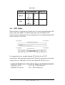
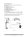
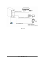
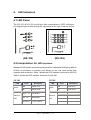
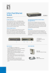
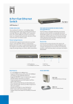
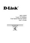
NS-105/NS-108 5-Port/8-Port Switch
10/100 Fast Ethernet Switch
Installation Guide
( Ver 1.1 , May/2005 )-----1
1.
1.1
1.2
Table of Contents
Introduction…………………………………………………… 3
Features………………………………………………………… 5
Specifications…………………………………………………... 6
2
2.1
2.2
Installing the Switch………………………………………….. 8
Unpacking……………………………………………………… 8
Checking Power…………………………...…………………… 8
3.
3.1
3.2
3.3
3.4
Making Network Connections………………………………..
Network Switched Ports………………………………………..
UTP Cable……………………………………………………...
UTP Connections…………...…………………………………..
Operating Mode………………………………………………..
4.
4.1
4.2
LED Indicators……………………………………………….. 14
LED Panel……………………………………………………… 14
Interpretation……………………………………........................ 14
( Ver 1.1 , May/2005 )-----2
9
9
10
11
13
1. Introduction
NS-105/NS-108 Industrial Switches are DIN-Rail mounting and
designed for industrial environments. Their rugged packaging and
protected circuitry keep them working under conditions that may
cause office-grade units to fail.
Industrial Ethernet applications are demanding - This 5-port/8-port
Fast Ethernet switch become the basic unit of the whole Ethernet
network. It is also the good companion of our I-7188EX and I-8000
ethernet embedded controller. The NS-105/NS-108 comes with
multiple ports, each capable of transmitting or receiving information
simultaneously at full wire speed to control and allocate the network
bandwidth. Besides that, the NS-105/NS-108 Industrial Ethernet
Switch automatically determines and remembers where an
Ethernet device is located and routes the messages only through
the appropriate port. This minimizes network loading and enables
true deterministic communications over Ethernet
Front Panel
Rear Panel
(NS-105)
( Ver 1.1 , May/2005 )-----3
Front Panel
Rear Panel
(NS-108)
The key features of this switch unit are:
Optimized Bandwidth : Combining five/eight 10/100Mbps-based
Fast Ethernet switched ports, the switch delivers a high network
bandwidth for your Fast Ethernet network
Easy Migration: With 10BASE-T support on each port, the switch
provides a non-disruptive and smooth migration path from Ethernet
to a Fast Ethernet network.
Easy Installation: With the functions of auto-speed-sensing and
auto-negotiation on each port, the switch supports plug-and-play
installation which eliminates configuration problems.
( Ver 1.1 , May/2005 )-----4
1.1 Features
IEEE 802.3 10BASE-T, IEEE802.3u 100BASE-TX and IEEE 802.3x
flow control standards
Five/Eight 10/100BASE-TX auto-negotiation switched ports for
flexible connections to desktop PCs, servers and Ethernet hubs.
The 10/100BASE-TX switched support :
Auto speed sensing for 100Mbps or 10Mbps connection
Auto Configuration with auto-negotiation devices
Full-duplex or half-duplex operation
Self learning for active MAC addresses
Store and forward switching to ensure only good packets are
forwarded
Forwarding and filtering at full wire speed
Supports IEEE 802.3x flow control for full-duplex operation
Supports back-pressure flow control for half-duplex operation
Comprehensive LED indicators provide quick, easy to read port and
switch information
(NS-108)
( Ver 1.1 , May/2005 )-----5
1.2 (NS-105)Specifications
Port 1-4
10BASE-T/100BASE-TX connectivity
One MDI-X RJ-45 jack
Port 5
10BASE-T/100BASE-TX connectivity
One MDI-X RJ-45 / MDI RJ-45 jack
(by Push Button setting)
Cables
10BASE-T Cat.3,4,5 UTP cable (100meters max.)
100BASE-TX Cat.5 UTP cable (100meters max.)
LED indicators
Power status
Link/Activity/Speed/Duplex/Collision status per port
Filtering rate
14,880pps for Ethernet(100BASE-T)
148,800pps for Fast Ethernet(100BASE-TX)
Forwarding rate
14,880pps for Ethernet(10BASE-T)
148,800pps for Fast Ethernet(100BASE-TX)
Filtering address Multicast/Broadcast/Unicast address
8K MAC address per unit
RAM buffers
256KB
Environment
Temperature
Relative humidity
Dimensions
70mm x 160mm x 120mm
Power
Requirement
Power
Consumption
00C to 600C
10% to 90% non-condensing
+10 ~ +30 VDC
0.08A@24Vdc; +/- 5%, arrowed.
( Ver 1.1 , May/2005 )-----6
(NS-108)Specifications
Port 1-8
10BASE-T/100BASE-TX connectivity
One MDI-X RJ-45 / MDI RJ-45 jack
Cables
10BASE-T Cat.3,4,5 UTP cable (100meters max.)
100BASE-TX Cat.5 UTP cable (100meters max.)
LED indicators
Power status
10/100Link/Activity/Speed/Duplex/Collision status
per port
Filtering rate
14,880pps for Ethernet(100BASE-T)
148,800pps for Fast Ethernet(100BASE-TX)
Forwarding rate
14,880pps for Ethernet(10BASE-T)
148,800pps for Fast Ethernet(100BASE-TX)
Filtering address Multicast/Broadcast/Unicast address
1K MAC address per unit
RAM buffers
64KB
Environment
Temperature
Relative humidity
Dimensions
70mm x 160mm x 120mm
Power
Requirement
Power
Consumption
00C to 600C
10% to 90% non-condensing
+10 ~ +30 VDC
0.24A@24Vdc; +/- 5%, arrowed.
( Ver 1.1 , May/2005 )-----7
2. Installing the Switch
2.1 Unpacking
Check to see that you have everything before you start the installation.
Installation guide
The switch unit
2.2 Checking Power
Since NS-105 consume 2W power(NS-108 consume 6W power),
make sure your power supply can meet this demand.
Input DC voltage range: 10~30V
The screw terminal of the DC power input is located on the front of the
switch as shown below:
+VS
GND
F.G.
Front Panel
(NS-105)
(NS-108)
( Ver 1.1 , May/2005 )-----8
3.0 Making Network Connections
3.1 Network Switched Ports
There are five/eight ports on the switch for connection to five/eight LAN
segments.
Each segment is an independent shared network in one collision-domain.
MDI-X
MDI
TP Port 1-4 (MDI-X jacks)
(NS-105)
(NS-108)
Five/Eight 10/100BASE-TX switched ports
Each port consists of one RJ-45 connector and is used for connection
to either a 10BASE-T or 100BASE-TX device. The RJ-45 connectors
are fixed MDI-X jacks, which are designed with internal crossover
function. It allows a connection to an end station using
straight-through UTP cable.
MDI Jack support for Port 5 (for NS-105)
One additional push button is provided for Port 5 to switch MDI-X or
MDI. It is useful when using Port 5 as an uplink port and using
straight-through UTP cable for the connection to any device.
(NS-105)
(NS-105)
Pin Definition
Port 1-4
Port 5
(Push Button Setting)
RJ-45
MDI-X
MDI
1
2
3
6
4,5,7,8
1
2
3
6
4,5,7,8
RX+
RXTX+
TXNC
TX+
TXRX+
RXNC
ˇ
ˇ
N/A
ˇ
( Ver 1.1 , May/2005 )-----9
(NS-108)
RJ-45
MDI-X
MDI
Pin Definition
1
2
3
6
4,5,7,8
1
2
3
6
4,5,7,8
RX+
RXTX+
TXNC
TX+
TXRX+
RXNC
Port 1-8
ˇ
ˇ
3.2 UTP Cable
When making a connection to another device using straight-through UTP
cable, make sure MDI-X to MDI connection rule is followed. The
following figure illustrates the pin assignments of a straight-through UTP
and a crossover UTP cable :
RJ-45 plug
1
2
3
6
RJ-45 plug
Straight-through UTP
RJ-45 plug
RJ-45 plug
1
2
3
6
1
2
3
6
Crossover UTP
1
2
3
6
It is suggested to use straight-through UTP cables for all UTP
connections. The maximum length and UTP cable categories used for the
connections to a 10BASE-T device and 100BASE-TX device are :
CONNECTED DEVICE UTP CABLE USED & MAXIMUM LENGTH
10BASE-T device
100BASE-TX device
Cat. 3,4,5 UTP(100meters)
Cat. 5 UTP(100meters)
( Ver 1.1 , May/2005 )-----10
3.3 UTP Connections
The NS-105/NS-108 switch can support connections to the
following devices:
10BASE-T network cards
10/100BASE-TX network cards
10BASE-T hub ports
100BASE-TX hub ports
10/100BASE-TX dual speed hub ports
10/100BASE-TX switch ports
Ethernet devices
Ethernet Embedded controller, such as I-7188EX, I-7188EA,
I-8430,I-8431, I-8830, I-8831,I-8437, I-8837, I-8438, I-8838
The following figure shows some connection examples and also
specifies the maximum distance of each connections:
10BASE-T hub
1X
UTP cable (100 meters max.)
2X
3X
4X
5X
6X
7X
8X
UPLink
MDI
MDI-X
10BASE-T or
10/100BASE-TX
network card
UTP cable (Cat.3, 1, or 5 UTP 100 meters max.
CTS 1
RTS 1
RXD
1
TXD 1
INIT
*
D2+
D2 +Vs
GND
I-7188EX
Cat.5 UTP(100 meters max.)
Programable controller with
10BASE-T or 100BASE-TX Ethernet port
(NS-105)
( Ver 1.1 , May/2005 )-----11
(NS-108)
( Ver 1.1 , May/2005 )-----12
3.4 Operating Mode
All switched ports are designed as auto-negotiation capable switched
ports. Each port can determine the speed and duplex type used
automatically through an auto-negotiation process with the remote
connected auto-negotiation device. The auto-negotiation process is
performed when the connection is made.
When connecting to a non-auto-negotiation device, each TP port also
features the capability to auto-sense the connection speed.
The following table lists the operation mode used for the switched port
when it connects to different devices. The operating mode includes the
connection speed and duplex type.
Connected Device
10BASE-T hub
100BASE-TX hub
Auto-negotiation device
Non-auto*1 half-duplex
device
Non-auto full-duplex device
Operation Mode Used
10Mbps, half-duplex
100Mbps, half-duplex
Auto-negotiation*2
Auto-speed-sensing *3,
half-duplex
Not supported
*1 Non-auto : non-auto-negotiation
*2 determined through auto-negotiation process
*3 speed is determined by auto-sensing function
Most of 10BASE-T hubs and 100BASE-TX hubs are non-autonegotiation devices and operate on half-duplex mode.
( Ver 1.1 , May/2005 )-----13
4. LED Indicators
4.1 LED Panel
The NS-105 & NS-108 switch provides comprehensive LED indicators
for diagnosing and monitoring the operation of the unit as shown below:
(NS-105)
(NS-108)
4.2 Interpretation for LED functions:
Standard RJ45 female connectors are provided. A standard RJ45 plug cable is
all that is necessary to connect your device to the unit since switch that
supports auto crossover. Table 1 shows the LED indicator functions for NS-105.
Table 2 shows the LED indicator functions for NS-108.
NS-105
NS-108
LED
Color
Red
Description
Power is On
Power
Color
Description
Red
Power is On
Power
Off
Power is Off
Off
Power is Off
Green On
Full-duplex
Red On
Link/Act
Ethernet
Red Off
Not Networking
Red On
Half-duplex
Port
Green On
Link to 100 Mbps
Green Off
Link to 10 Mbps
Ethernet
Port
LED
Green/Red
Traffic Collisions
( Ver 1.1 , May/2005 )-----14