1
7188E Series
7188E Series Software User’s Manual
7188E Series New Features
1. Virtual COM Technology
Your Powerful Tools
2. Ethernet I/O Technology
3. Web-server Technology
Create New Ideas
4. MiniOS7 & Xserver Inside
5. I/O Expansion Bus Inside
Create New Applications
6. Time to market & Cost Effective Solution
Warranty
All products manufactured by ICP DAS are warranted against defective
materials for a period of one year from the date of delivery to the original
purchaser.
Warning
ICP DAS assume no liability for damages consequent to the use of this product.
ICP DAS reserves the right to change this manual at any time without notice.
The information furnished by ICP DAS is believed to be accurate and reliable.
However, no responsibility is assumed by ICP DAS for its use, nor for any
infringements of patents or other rights of third parties resulting from its use.
Copyright
Copyright 2002 by ICP DAS. All rights are reserved.
Trademark
The names used for identification only may be registered trademarks of their
respective companies.
7188E Series Software User’s Manual, 2004, v2.1, 7MS-003-21 ----- 1
Table of Contents
1.
2.
3.
4.
5.
INTRODUCTION ..............................................................................................................................................................3
1.1
3 TYPICAL APPLICATIONS .............................................................................................................................................4
1.2
DIRECTORY TREE OF SOFTWARE AND LITERATURE ......................................................................................................8
1.3
SOFTWARE INSTALLATION .........................................................................................................................................10
1.4
SOFTWARE UTILITIES .................................................................................................................................................13
1.5
PC DIAGNOSTIC TOOLS ..............................................................................................................................................17
MINIOS7 OF THE 7188E SERIES.................................................................................................................................20
2.1
MINIOS7 FOR THE 7188E SERIES ...............................................................................................................................20
2.2
DEMO PROGRAMS FOR THE 7188E SERIES .................................................................................................................23
VXCOMM APPLICATIONS ..........................................................................................................................................24
3.1
OVERVIEW .................................................................................................................................................................24
3.2
INSTALLING THE VXCOMM DRIVER ...........................................................................................................................27
3.3
ADDING A 7188E/8000E SERVER AND CONFIGURING THE VXCOMM DRIVER ............................................................29
3.4
REMOVING A 7188E/8000E SERVER ..........................................................................................................................37
3.5
UNINSTALLING THE VXCOMM DRIVER ......................................................................................................................39
3.6
DIAGNOSTICS AND TROUBLE SHOOTING ....................................................................................................................40
3.7
FAQ...........................................................................................................................................................................52
ETHERNET I/O APPLICATIONS ................................................................................................................................53
4.1
OPERATION PRINCIPLE OF THE XSERVER ...................................................................................................................53
4.2
COMMAND PROTOCOL OF XSERVER ..........................................................................................................................54
4.3
DEMO PROGRAM LIST OF XSERVER ............................................................................................................................66
4.4
CLIENT PROGRAM LIST FOR XSERVER ........................................................................................................................69
4.5
PROGRAMMING OF XSERVER .....................................................................................................................................72
4.6
USING CLIENT PROGRAMS ..........................................................................................................................................79
4.7
DEMO PROGRAMS OF XSERVER .................................................................................................................................88
GLOSSARY ....................................................................................................................................................................102
7188E Series Software User’s Manual, 2004, v2.1, 7MS-003-21 ----- 2
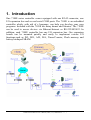
1. Introduction
One 7188E series controller comes equipped with one RJ-45 connector, one
I/O expansion bus and several serial COM ports. The 7188E is an embedded
controller which, with aid of c language, can help you develop your own
programs. Included with the 7188E are many demos and libraries. The 7188E
can be used to access devices via Ethernet/Internet or RS-232/485/422. In
addition, each 7188E controller has one I/O expansion bus. Our expansion
boards can be mounted quickly and easily to implement various I/O
functions,such as D/I, D/O, A/D, D/A, Timer/Counter, Flash memory and
battery backuped SRAM.
7188E Series Software User’s Manual, 2004, v2.1, 7MS-003-21 ----- 3
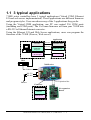
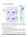
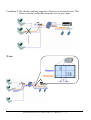
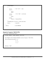
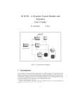
1.1 3 typical applications
7188E series controllers have 3 typical applications (Virtual COM, Ethernet
I/O and web server implementation). These applications use different firmware
and program styles. Users can choose any of the 3 applications they prefer.
Using the Virtual COM application, one PC can control 256 COM ports
(including real COM ports). The VxComm firmware will turn your 7188E into
a RS-232 to Ethernet/Internet converter.
Using the Ethernet I/O and Web Server applications, users can program the
firmware of the 7188E (Xserver, Web server).
Application
VxComm
TCP/IP
Application
Program
Rs-232
Virtual COM
TCP/UDP
Ethernet I/O
Browser
( IE, Netscape)
Web server
Hub
7188E series
Ethernet
RS-232
RS-485
Device
I/O Expansion Bus
Firmware
Vxcomm
Xserver
I/O expansion
Board
Web server
7188E Series Software User’s Manual, 2004, v2.1, 7MS-003-21 ----- 4
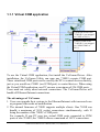
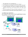
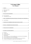
1.1.1 Virtual COM application
Expansion board of the
7188E(IP-1) are mapped
to COM3 of PC(1)
COM1/COM2 of the
7188E(IP-1) are mapped
to COM4/COM5 of
PC(1)
To use the Virtual COM application, first install the VxComm Driver. After
installation, the VxComm Utility can map any 7188E’s remote COM port.
These virtualized COM ports can be used by the PC to control devices directly,
just as you would use COM1 (real COM port) to control devices. When using
the Virtual COM application, one PC can use a maximum of 256 COM ports.
Users need not worry about network connections. The VxComm Driver will
handle all Ethernet/Internet connections.
The advantages of VxComm:
1. Users can upgrade their systems to the Ethernet/Internet with increased ease
as program code needs no modification.
2. The internal firmware of 7188E supports multiple clients. One 7188E can
handle a maximum of 30-N socket connections simultaneously, with N
being the number of the 7188E’s COM ports.
For example: If one PC uses two virtual COM ports connected to COM
ports of one 7188E2, the 7188E2 allows a maximun of 14 PC connections.
7188E Series Software User’s Manual, 2004, v2.1, 7MS-003-21 ----- 5
1.1.2 Ethernet I/O application
The Xserver is a powerful program designed for Ethernet I/O applications. It
supplies the 7188E with a range of flexible options. Users can modify the
Xserver to control all of the 7188E’s hardware: COM ports, I/O expansion
boards, a 7 Seg LED, or other relevant products.
The advantages of the Xserver:
1. We design, maintain, update the Xserver for all users.
2. Xserver can be easily modified through the use of general development
tools such as TC/BC/MSC. All relative libraries are coded in C language.
3. High running speed. The original Xserver (Demo4.exe) can run about 750
scan loops per second (version 2.6.14).
4. Most program code of the Xserver is finished. Ethernet/Internet
communication and program loop control are all finished in VxComm.lib.
7188E Series Software User’s Manual, 2004, v2.1, 7MS-003-21 ----- 6
This vastly reduces user’s developing time.
5. To modify Xserver, users need only to modify the 6 functions
6. The command protocol is designed to fit most of the 7188E’s requirements.
7. Users can develop and extend their private command protocol very easily.
8. It supports multi-clients. The Xserver can handle a maximum of 30-N
connections simultaneously, with N being the number of the 7188E’s COM
ports.
9. Auto wake up option. The Xserver will check on packet timeouts. If the
software crashes, the Xserver will wake itself up automatically.
10. The Xserver demos (TC/BC/MSC) and Client demos (VB/VC) are included.
1.1.3 Web server application
With the help of Web server, users are able to use standard browsers (such as
IE or Netscape) to access the I/Os of the expansion boards or devices
connected to any of the 7188E’s COM port.
7188E Series Software User’s Manual, 2004, v2.1, 7MS-003-21 ----- 7
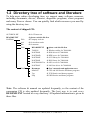
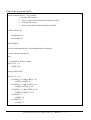
1.2 Directory tree of software and literature
To help users reduce developing time, we support many software resources,
including documents, drivers, libraries, diagnostic programs, client programs
and many Xserver demos. You can quickly find which resources you need by
using the directory tree.
The content of shipped CD:
AUTORUN.INF
Æ for CD auto run
README.TXT
NAPDOS
Æ please read this file first
Æ Company web site
Æ for Acrobat reader
Æ for autorun
Web
Ar4
Bin
7000
7188E
README.TXT
7000Util
NAP7000S
NAP7000D
NAP7000X
NAP7000P
NAP7000OPCSvr
NAP7000V
Document
MiniOS7
Tcp
Udp
Æ please read this file first
Æ Windows utility for 7000/8000
Æ DOS driver for 7000/8000
Æ DDE server for 7000/8000
Æ OCX library for 7000/8000
Æ DLL library for 7000/8000
Æ OPC server for 7000/8000
Æ LabView driver for 7000/8000
Æ User’s manuals and application notes
Æ CPU and I/O libraries and demo programs
Æ TCP libraries and demo programs
Æ UDP libraries and demo programs
Note: The software & manual are updated frequently, so the content of the
companion CD is also updated frequently. The best way is to read every
README.TXT located in every directory. All updated information is given in
these files.
7188E Series Software User’s Manual, 2004, v2.1, 7MS-003-21 ----- 8
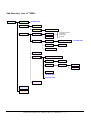
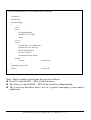
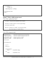
Sub directory tree of 7188E:
7188E
Document
MiniOS7
Readme.htm
Demo
Doc
TCP
PCDiag
VxComm
Big5/Eng/Gb2312
Source
1. Configure Wizard
2. Send232
3. Send TCP
4. 7188E
Doc
Big5/Eng/Gb2312
Setup
Driver(PC)
vxcomm.htm
NT/2K/XP
Server(7188e)
Web-Server
Xserver
7188EA/7188E2/.../7188E8
Client
VB/VC
Demo
BC/MSC/TC
Demo
Lib
v7000
Xserver.htm
Function.htm
Other
UDP
Other
7188E Series Software User’s Manual, 2004, v2.1, 7MS-003-21 ----- 9
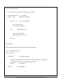
1.3 Software Installation
1.3.1 Installation Steps
The installation steps are given as follows:
Step 1: Change the directory to the destination folder as follows.
For example (CD-ROM Drive is "D:")
C:\>d:
D:\>cd \NAPDOS\7188E\
D:\NAPDOS\7188E\>_
Step 2: Make a new directory for the 7188E. Xcopy all files.
C:\>md 7188E
C:\>cd 7188E
C:\7188E\>xcopy d: c: /s /v
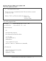
1.3.2 Installing 7188X.exe/7188XW.exe
The 7188X.exe/7188XW.exe is used to download and debug programs.
Users should copy it to the PATH directory first. Then user can execute
7188X.exe/7188XW.exe in any directory on the host-PC. The installation steps
are given as follow:
Step 1: Change the directory to the destination folder as follows.
For example (CD-ROM Drive is "D:")
C:\>d:
D:\>cd \NAPDOS\7188E\MiniOS7
D:\NAPDOS\7188E\MiniOS7\>_
Step 2: Copy 7188X.EXE from CD to the PATH directory (defined in PATH).
C:\>cd windows
C:\windows\>copy d:7188x.exe
Note: 7188XW.exe is designed for win32 system. So it can be used for USBRS232 or PCMCIA-RS232 port.
7188E Series Software User’s Manual, 2004, v2.1, 7MS-003-21 ----- 10
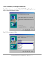
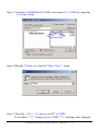
1.3.3 Installing PC diagnostic tools
Step1: Run Setup.exe from the 7188e\TCP\PCDiag\Setup directory.
Setp2: Choose destination folder.
Step3: Select program folder.
7188E Series Software User’s Manual, 2004, v2.1, 7MS-003-21 ----- 11
Step4: Start copying files.
After finished installing, 5 items can be found in the PCDiag group.
7188E Series Software User’s Manual, 2004, v2.1, 7MS-003-21 ----- 12
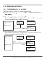
1.4 Software Utilities
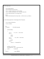
1.4.1 7188X.EXE Utility for Host-PC
The utility program, 7188X.EXE, can be used as follows:
z Downloads user’s programs from host-PC into 7188, 7188X, 7188E and
8000 families.
z Shows debug string to monitor of host-PC
Three standard output libraries, Putch, Print & Puts, will allow main control
unit to send output string to monitor of Host-PC.
Monitor of host-PC
7188X/7188E/8000
Main()
{
Print(“\nTest 123”);
…………………
}
Test 123
RS-232
115200, N81
COM1
COM1/2
Host-PC
Run 7188X.EXE
z Keys-in test data from keyboard of host-PC
Three standard input libraries, Getch, Scanf & LineInput, will allow main
control unit to read keyboard from Host-PC.
Monitor of host-PC
7188X/7188E/8000
Main()
{
float r;
…………………
Scanf(“\n%f”,&r);
Print(“\nR=%f”,r);
…………………
}
RS-232
115200, N81
R=3.14159
COM1
COM1/2
Host-PC
Run 7188X.EXE
3.14159
Keyboard of host-PC
7188E Series Software User’s Manual, 2004, v2.1, 7MS-003-21 ----- 13
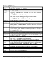
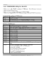
Hot-key of 7188x.exe:
Command Description
F1
Shows help messages of 7188x.exe
Alt_1
Uses PC's COM1
Alt_2
Uses PC's COM2
Alt_C
Switches to command mode to change PC COM port’s baudrate
and data format.
Press ENTER to confirm the setting.
Press LEFT/RIGHT arrow key to select different field.
Press Any key to switch different values.
Press ENTER in the last field will stop this operation.
Alt_D
Sets the date of RTC to the PC's date.
Alt_T
Sets the time of RTC to the PC's time
Alt_E
For downloading files into memory. Only after the message
“Press ALT_E to download file!” is shown on screen, can users
press Alt_E.
Alt_L
Switches normal/line mode. In line-mode, all characters-pressed
will not send to COM until the ENTER is pressed. It is designed
for testing the 7000 series.
Alt_X
Quits 7188X.EXE.
F2
Sets the file name for download (without download operation).
Alt_F2
Sets multiple filenames for download. (10 files maximum. If set
less then 10 files, add '*' to end.)
Ctrl_F2 Shows COM1 & COM2 messages (for easily COM port testing).
Press ALT_X to return to the original mode.
Press TAB to switch the cursor between these two windows.
F5
Runs the program specified by F2 and arguments set by F6.
F6
Sets the arguments of the execution file set by F2. (10 arguments
maximum. If set less than 10 arguments, add ‘*’ to end).
F8
F8=F9+F5.
F9
Downloads the file specified by F2 into FLASH memory.
Alt_F9
Downloads all files specified by ALT_F2 into FLASH memory.
F10
Downloads the file specified by F2 into SRAM and execute it.
F12
For 7521/7522/7523 to test RS-232.
… more … … more …
7188E Series Software User’s Manual, 2004, v2.1, 7MS-003-21 ----- 14
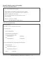
1.4.2 7188XW.EXE Utility for Host-PC
7188xw.exe is the Win32 version of 7188x.exe. The difference beteween
7188x.exe and 7188xw.exe is:
7188x.exe: Uses standard COM ports (COM1/COM2).
7188xw.exe: Supports RS-232 COM ports using USB and PCMCIA interfaces.
Command line options of 7188xw.exe:
Option
Description
/c#
Uses PC's COM#
/b#
Sets baudrate of PC’s COM port (default is 115200)
/s#
Sets screen’s display-rows (default is 25, max. is 50)
Hot-key of 7188xw.exe:
Command Description
F1
Shows help messages of 7188xw.exe
Alt_F1
Shows the Chinese (Big5) help messages of 7188xw.exe
Ctrl_F1 Shows the Chinese (GB2312) help messages of 7188xw.exe
Alt_1
Uses PC's COM1
Alt_2
Uses PC's COM2
Alt_3
Uses PC's COM3
Alt_4
Uses PC's COM4
Alt_5
Uses PC's COM5
Alt_6
Uses PC's COM6
Alt_7
Uses PC's COM7
Alt_8
Uses PC's COM8
Alt_9
Uses PC's COM9
Alt_A
Switches between normal mode and ANSI-Escape-code-support
mode
Alt_C
Switchs to command mode. Supports commands:
b#: sets new baudrate of PC’s COM ports.
c#: Uses PC’s COM#.
n/e/o: sets parity to none/even/odd.
5/6/7/8: sets data bits to 5/6/7/8.
p#: sets PC’s working directory.
q: quits command mode.
7188E Series Software User’s Manual, 2004, v2.1, 7MS-003-21 ----- 15
Alt_D
Alt_T
Alt_E
Sets the date of RTC to the PC's date.
Sets the time of RTC to the PC's time
For downloading files into memory. Only after the message
“Press ALT_E to download file!” is shown on screen, can users
press Alt_E.
Alt_H
Switches Hex/ASCII display mode.
Alt_L
Switches normal/line mode. In line-mode, all characters-pressed
will not send to COM until the ENTER is pressed. It is designed
for testing the 7000 series.
Alt_X
Quits the 7188X.EXE.
F2
Sets the file name for download (without download operation).
F5
Runs the program specified by F2 and arguments set by F6.
Alt_F5
Runs the program stored in SRAM.
F6
Sets the arguments of the execution file set by F2. (10 arguments
maximum. If set less than 10 arguments, add ‘*’ to end).
Ctrl_F6 Clears screen.
F8
F8=F9+F5.
F9
Downloads the file specified by F2 into FLASH memory.
Alt_F9
Downloads all files specified by ALT_F2 into FLASH memory.
F10
Downloads the file specified by F2 into SRAM and execute it.
Alt_F10 Downloads the file specified by F2 into SRAM memory.
Ctrl_B
Sends a BREAK signal to the PC’s COM port that is used by
7188xw.exe.
… more … … more …
7188E Series Software User’s Manual, 2004, v2.1, 7MS-003-21 ----- 16
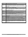
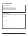
1.5 PC Diagnostic tools
The PC Diagnostic tools include:
¾ Configure Wizard: guides users step by step in configuring the
7188E/8000E’s network setting.
Please refer to sec. 3.3 of “7188E Series Hardware user’s manual” for more
operating details.
7188E Series Software User’s Manual, 2004, v2.1, 7MS-003-21 ----- 17
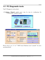
¾ Send232: uses serial port (RS-232) interface to communicate with devices.
Can be used to test the Virtual COM technology.
Please refer to sec. 3.6 for more operating details.
¾ SendTCP: uses TCP protocol to communicate with the 7188E/8000E and
devices which are connected to the 7188E/8000E’s COM ports.
Please refer to sec. 4.6 for more operating details.
7188E Series Software User’s Manual, 2004, v2.1, 7MS-003-21 ----- 18
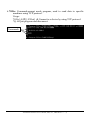
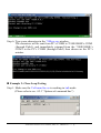
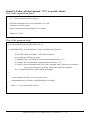
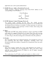
¾ 7188e: Command-prompt mode program, used to send data to specific
machines using TCP protocol.
Usage:
7188e [-S:IP] [-P:Port] Æ Connect to a device by using TCP protocol.
*Q Æ Quit program and disconnect.
Commands
7188E Series Software User’s Manual, 2004, v2.1, 7MS-003-21 ----- 19
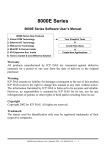
2. MiniOS7 of the 7188E Series
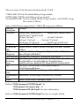
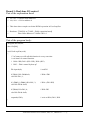
2.1 MiniOS7 for the 7188E Series
The MiniOS7 is an embedded O.S. designed for the following families:
z
z
z
z
z
z
z
z
7188XA/7188XB/7188XC series
7521/7522/7523 series
7188EA/7188EX/7188EX-256 series
7188E1/7188E2/7188E3/7188E4/7188E5/7188E8 series
8000 series.
Iview-100 series
More new embedded controller families
It is used to replace the ROMDOS used in the 7188 series. Several brands
of DOS have been created by various companies. In all cases, DOS, whether
PC-DOS, MS-DOS, or ROM-DOS, is a set of commands or code which tells
the computer how to process information. DOS runs programs, manages files,
controls information processing, directs input and output, and performs many
other related functions. The MiniOS7 provides equivalent functions of
ROMDOS and provides more specfic functions for the 7188X/7521/8000
family.
Comparison between MiniOS7 and ROM-DOS:
Function
Power up time
Supports I/O expansion bus
Supports AsicKey
Supports hardware unique serial number
Supports MMI, Iview-100 series
Supports Ethernet 10M interface, 7188E & 8X3X series
Directly downloads executable programs into Flash ROM
O.S. updateable (downloadable)
Built-in hardware diagnostic functions
Directly controls 7000 series modules
Customers ODM functions
Free of charge
MiniOs7
0.1 sec
Yes
Yes
Yes
Yes
Yes
Yes
Yes
Yes
Yes
Yes
Yes
7188E Series Software User’s Manual, 2004, v2.1, 7MS-003-21 ----- 20
RomDos
4 ~ 5 sec
No
No
No
No
No
No
No
No
No
No
No
Note: We reserve the right to change the specifications of MiniOS7 without
notice.
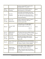
Command Set of MiniOS7:
Command
Description
LED5 pos value
Shows a HEX value in the specified position of 5-digit LED.
USE NVRAM
Into the service routine for read/write NVARM.
USE EEPROM
Into the service routine of read/write EEPROM.
USE Flash
Into the service routine of read/write Flash-ROM.
USE COM2 /option Into the service routine of send/receive to/from COM2 (RS-485).
DATE
Sets the date of RTC.
[mm/dd/yyyy]
TIME [hh:mm:ss]
Sets the time of RTC.
MCB
Tests current memory block.
UPLOAD
The first step to update the MiniOs7.
BIOS1
The last step to update the MiniOs7.
LOAD
DOWNLOADs the user program into the Flash-Memory.
DIR [/crc]
Shows the information of all files download in the Flash-Memory.
RUN [fileno]
Runs the file with file-number=fileno, no fileneÆthe last file.
Name
Runs the file with file-name=name.
DELETE (or DEL) Deletes all files stored in the Flash-Memory. It will delete all files.
RESET
Resets the CPU.
DIAG [option]
Hardware Diagnostic.
BAUD baudrate
Sets the new value of communication-baudrate to baudrate.
TYPE filename [/b] Lists content of the file.
REP [/#] command Repeats executing the same command # times.
RESERVE [n]
Reserves n Flash Memory sectors for USER's programs.
LOADR
Downloads a file into SRAM.
RUNR [param1
Runs a program saved into SRAM (downloaded by command
[param2...]]
LOADR).
I/INP/IW/INPW port Reads data from the hardware PORT.
O/OUTP/OW/OUTP Outputs to hardware PORT.
W port value
… more …
… more …
*** Refer to 7188E\MiniOS7\DOC\Index.htm for user’s manual & demo
programs for the MiniOS7 ***
7188E Series Software User’s Manual, 2004, v2.1, 7MS-003-21 ----- 21
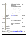
There are some of the libraries included with the 7188E.
7188EL.LIB: CPU & I/O related library (Large model)
TCPIPL.LIB: TCP/IP related library (Large model)
VComNNNN.LIB: Xserver related library (Large model), with NNNN being
the version of library.
Some of the libraries supported by 7188E.LIB are given as follows:
Function
Example
description
COM port
InstallCom1, InstallCom2, ……, InstallCom5, InstallCom36,
InstallCom47, InstallCom58
IsCom1, IsCom2,………………, IsCom7, IsCom8
ToCom1, ToCom2, ……, ToCom7, ToCom8
ReadCom1, ReadCom2, ………, ReadCom7, ReadCom8
EEPROM
WriteEEP, ReadEEP, EnableEEP, ProtectEEP
NVRAM &
ReadNVRAM, WriteNVRAM, GetTime, SetTime, GetDate,
RTC
SetDate
LED &
LedOn, LedOff, LedToggle, Init5DgitLed, Show5DigitLed,
5DigitLed
Show5DigitLedWithDot
Flash Memory FlashReadId, FlashErase, FlashRead, FlashWrite
Timer &
TimerOpen, TimerClose, TimerResetValue, TimerReadValue
Watchdog
StopWatchReset, StopWatchRead, StopWatchStop
Timer
InstallUserTimer EnableWDT, DisableWDT, RefreshWDT
File
GeFileNo, GetFileName, GetFilePositionByNo,
GetFilePositionByName
Connects to
SendCmdTo7000, ReceiveResponseFrom7000
7000
Programmable SetDio4Dir, SetDio4High, SetDio4Low, GetDio4
I/O
Others
Kbhit, Getch, Putch, LineInput, Scanf
Refer to 7188e\document\TCPIPLib.pdf &
7188e\minios7\doc\index.htm &
7188e\document\WebLib.pdf for more information.
Refer to 7188e\document\TCPIPLib.pdf for how to compile & link.
7188E Series Software User’s Manual, 2004, v2.1, 7MS-003-21 ----- 22
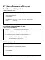
2.2 Demo Programs for the 7188E Series
We provide hundreds of demo programs for users. The source codes are all in
the shipped CD. It is recommended to edit & modify these demo programs
when starting user’s special applications. The demo programs can be classed as
follows:
Some of the demo programs designed for MiniOS7 are given as follows:
Demo
Description
Hello
Can run on PC or 8000, just use Print() to print:
"*** Hello 8000 ***"
Hello1
Demo for using functions: Is8000, GetLibVersion, Print
Hello2
Demo for using C++ compiler.
FILE
Demo information in obtaining file information and file position
in Flash memory. All file data is stored in Flash Memory.
In MiniOS7, cannot use C's functions: fopen, fclose, fread,
fwrite.
BATCH
An example of BATCH files (*.BAT).
SCANF
Demo for using LineInput and Scanf.
RUNPROG Uses Ungetch to send commands to MiniOS7 to run another
program
DEMO90-98 Demos for using TIMER functions.
Location: 7188e\MiniOS7\Demo\*.*
Some typical TCP/IP demo programs are given as follows:
Typical TCP/IP demo
7188E
PC
Ping demo
Client, ping.exe
None
Telnet server demo
Server, telserv.exe Client, telnet.exe
Telnet server demo2
Server, telserv2.exe Client, telnet.exe
Demo1: TCP/IP demo
Server, demo1.exe Client, Client1.exe
Demo2: TCP/IP demo
Server, demo2.exe Client, Client1.exe
Demo3: TCP/IP demo
Server, demo3.exe Client, Client1.exe
Location: 7188e\TCP\Other\*.*
Refer to Sec. 4.7 for more TCP/IP demo program designed for Xserver.
Refer to 7188e\document\TCPIPLib.pdf,
7188e\minios7\doc\index.htm and
7188e\document\WebLib.pdf for more information.
Refer to sec. 5.2 for how to compile and link.
7188E Series Software User’s Manual, 2004, v2.1, 7MS-003-21 ----- 23
3. VxComm Applications
•
•
•
•
•
•
•
Overview
Installing the VxComm Driver
Adding a 7188E/8000E server and configuring the VxComm Driver
Removing a 7188E/8000E server
Uninstalling the VxComm Driver
Diagnostics and Trouble Shooting
FAQ
3.1 Overview
The VxComm (Virtual Comm) Driver and VxComm Utility are very easy
to install and use. The first thing to do is to find the installation file in the
included CD. The directory is:
¾ 7188e\TCP\VxComm\NT\VxCommNT.exe
(for Windows NT 4.0) or
¾ 7188e\TCP\VxComm\2K\VxComm2K.exe
(for Windows 2000, Windows XP).
This document shows how to install and configure the driver correctly.
There are three parts to the quick start manual. The first part instructs users
how to install the software. The second part shows how to add a 7188E/8000E
server and configure a COM port. Finally, the third part teaches you how to
remove a 7188E/8000E server.
7188E Series Software User’s Manual, 2004, v2.1, 7MS-003-21 ----- 24
3.1.1 Architecture
The VxComm Driver creates COM port(s) and maps them to the COM
port(s) of the 7188E/8000E. The user's RS-232 client programs need only to
change to the different COM port to access the serial devices that are allocated
to the Internet or Ethernet network via the 7188E/8000E.
7188E Series Software User’s Manual, 2004, v2.1, 7MS-003-21 ----- 25
3.1.2 Ports mapping
Vxcomm Driver/Utility supports Port 1 to Port 8 in accessing COM1 to
COM8 of the 7188E/8000E. Another Port I/O is designed to access the I/O
boards mounted on 7188E or 8000E.
With the help of the VxComm Driver/Utility, uses can map remote COM port
and I/O boards to become a virtual COM port of PC. One PC can control a
maximun of 256 COM ports (including COM1 and COM2).
Local COM Port
(PC)
COM ?
COM ?
COM ?
COM ?
COM ?
COM ?
COM ?
COM ?
COM ?
VxComm Driver/Utility Remote COM port
(PC)
(7188E/8000E)
Port 1
COM1
Port 2
COM2
Port 3
COM3
Port 4
COM4
Port 5
COM5
Port 6
COM6
Port 7
COM7
Port 8
COM8
Port I/O
I/O board
7188E Series Software User’s Manual, 2004, v2.1, 7MS-003-21 ----- 26
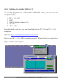
3.2 Installing the VxComm Driver
Step 1: Run VxComm2K.exe (for Windows2000, Windows XP) or
VxCommNT.exe (WindowsNT4.0) or VxComm98.exe from the
\Napdos\7188e\Tcp\VxComm\driver (pc)\2k or NT or 9x directory.
Step2: Choose a destination folder.
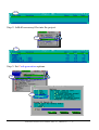
Step 3: Choose a program folder.
7188E Series Software User’s Manual, 2004, v2.1, 7MS-003-21 ----- 27
Step 4: Select the "Yes, ... " option and click the "Finish" button to reboot your
computer.
Step 5: After rebooting the computer, the VxComm Utility will ask you to
configure the virtual COM port(s). Please refer to the next section for
more information.
Note:
The Vxcomm driver is located on 7188e\Tcp\VxComm\driver (pc)
7188E Series Software User’s Manual, 2004, v2.1, 7MS-003-21 ----- 28
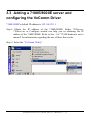
3.3 Adding a 7188E/8000E server and
configuring the VxComm Driver
7188E/8000E's default IP address is 192.168.255.1.
Step1: Obtain the IP address of the 7188E/8000E. Either 7188x.exe,
7188xw.exe or Configure wizard can help you in obtaining the IP
address of the 7188E/8000E. Refer to Sec. 3 of “7188E hardware user’s
manual” for information regarding the use of these three tools.
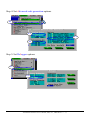
Step 2: Select the "VxComm Utility".
7188E Series Software User’s Manual, 2004, v2.1, 7MS-003-21 ----- 29
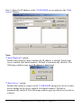
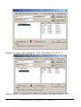
Step 3: Enter the IP address of the 7188E/8000E server and press the "Add
Server" Button.
Note:
"Check Duplicate" option:
Enable this option to check whether the IP address is already listed in the
server window (left-hand window). Default is automatically checked. The
following window pops up if IP address is duplicated.
"Check Server" option:
Enable this option to connect to the 7188E/8000E and get the device's name
before adding to the server window (left-hand window). Default is
automatically checked. The following window pops up if host/server fails to
connect.
7188E Series Software User’s Manual, 2004, v2.1, 7MS-003-21 ----- 30
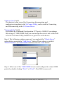
"Timeout (ms)" field:
This timeout value is used for Connecting, disconnecting and
sending/receiving data in the VxComm Utility, and is used for Connecting
and Disconnecting in the VxComm Driver.
"Command Port" field:
By default, the Command/Configuration TCP port is 10,000. If you change
the setting of 7188E/8000E, then you must assign the correct one in this field
to let the VxComm Utility and Driver to get access to the device.
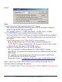
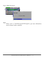
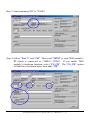
Step 4: The following window pops up if you uncheck the "Check Server"
option before pressing the "Add Server" button. Please choose a suitable
"Model Number" of 7188E/8000E and then click the "OK" button.
Step 5: Select one of the 7188E/8000E devices and configure the virtual COM
port(s) by double clicking "Port1" or "Port2". (Port7000 is reserved.)
7188E Series Software User’s Manual, 2004, v2.1, 7MS-003-21 ----- 31
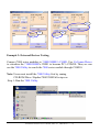
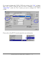
Another example when adding the 8430 at IP address 10.10.34.12.
Step 6: Select an appropriate COM port number, and then click the "OK"
7188E Series Software User’s Manual, 2004, v2.1, 7MS-003-21 ----- 32
button.
Note:
"Assign following COM number sequentially" option:
This option will assign the following ports with the available COM port
number sequentially and automatically.
For example: If Port1 = COM4, then Port2 = COM5, Port3 = COM6
"Use 7188E/8000E current setting (Fixed Config)" option:
You can click the "Port Configuration" button to configure this port's Baud
rate and Data format settings. After the configuration, you can then check
this option.
Fixed Configuration (Use 7188E/8000E's current setting):
By using this feature, the VxComm Driver would not change the
7188E/8000E's settings dynamically. This is proper when you have multiclients to access the same 7188E/8000E server.
Dynamic Configuration (This's the default method):
The VxComm Driver always change the 7188E/8000E's settings
dynamically. It is proper for working with several different baud rate and
data format.
For example, you may need to use 7000 Utility to make a search with
several baud rates on the RS-485 network.
Please also refer to "Configuring COM port of the 7188E/8000E server".
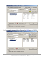
Step 7: Select one of the 7188E/8000E devices and then click the "Server
Options" button to configure the options.
(Note: VxComm Utility 98 does not support the "Server Options" function yet!)
7188E Series Software User’s Manual, 2004, v2.1, 7MS-003-21 ----- 33
Another example shown as follow: The port1 of 8430 map to COM20.
7188E Series Software User’s Manual, 2004, v2.1, 7MS-003-21 ----- 34
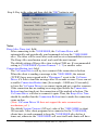
Step 8: Key in the value and then click the "OK" button to exit.
Notes:
Keep Alive Time (ms) field:
After connecting to the 7188E/8000E, the VxComm Driver will
automatically and periodically send commands to keep the 7188E/8000E
alive. The timer will be reset after each send/receive command/data success.
The Keep-Alive mechanism won't work until the next timeout.
The default setting of Keep-Alive time is about 7000 ms. It's recommended
setting is (7188E/8000E's System Timeout * 1 / 3) or smaller value.
Connection-Broken (ms) field:
The VxComm Driver will try to re-connect if the connection is broken.
When the client is sending a message to the 7188E/8000E, the internet
(TCP/IP) layer may respond with a "Disconnect" event to the VxComm
Driver if it fails to send the message after 20 seconds or more. Users can set
a smaller Connection-Broken time [for example : 10000 ms( 10 seconds)]
to force the VxComm Driver to re-connect again and get a quicker response.
If the connection has no sending/receiving signal before the ConnectionBroken time has timed out, the connection will be marked as broken. The
VxComm Driver will also re-connect it again. Thus, the Keep-Alive Time
should be smaller than the Connection-Broken time to make the connection
come on-line.
(Note: VxComm Driver 98 does not support the auto-reconnection
mechanism yet! )
The default System Timeout (/STxxx) value of the 7188E/8000E is about
300 seconds. After client programs have connected to the 7188E/8000E,
clients have to send command to keep the 7188E/8000E alive before it
times out, otherwise the 7188E/8000E will reset itself and clients will have
7188E Series Software User’s Manual, 2004, v2.1, 7MS-003-21 ----- 35
to reconnect to the 7188E/8000E again.
Users can set the Keep-Alive Time and Connection-Broken time to 0 to
disable this mechanism. The System Timeout will have to be set to 0 to
disable the reset mechanism.
Connect Timeout (ms) field:
The timeout value will be passed into MS TCP/IP driver for reference when
connecting and disconnecting.
Command TCP Port field:
By default setting, the 7188E/8000E use TCP port 10000 as the Command /
Configuration port. If you change the 7188E/8000E's setting, you must
assign the correct one in the field. So the VxComm Driver can connect to
the right TCP port.
This TCP port is used to configure the Baud rate, data format, CTS/RTS
control mode and Break, etc.
Port7000 Port field:
By default setting, the 7188E/8000E use TCP port 9999 as the Port7000
port. This TCP port is reserved.
Step9: Press the ‘Exit”button to save the settings and exit the VxComm
Utility.
7188E Series Software User’s Manual, 2004, v2.1, 7MS-003-21 ----- 36
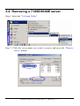
3.4 Removing a 7188E/8000E server
Step 1: Select the "VxComm Utility".
Step 2: Click the server name you want to remove and press the "Remove
Server" button.
7188E Series Software User’s Manual, 2004, v2.1, 7MS-003-21 ----- 37
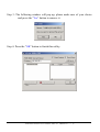
Step 3: The following window will pop up, please make sure of your choice
and press the "Yes" button to remove it.
Step 4: Press the "OK" button to finish this utility.
7188E Series Software User’s Manual, 2004, v2.1, 7MS-003-21 ----- 38
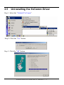
3.5
Uninstalling the VxComm Driver
Step 1: Select the "UnInstall VxComm".
Step 2: Click the "Yes" button.
Step 3: Click the "OK" button.
7188E Series Software User’s Manual, 2004, v2.1, 7MS-003-21 ----- 39
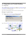
3.6 Diagnostics and Trouble Shooting
3.6.1 Diagnostics
After configuring the VxComm Driver by using the VxComm Utility, the
VxComm Driver should work without error. However, users can use a simple
test to make sure it's working properly.
Note: The test method depends on the user's devices and client programs.
Example 1: Loop-Back Testing
Step 1: Make sure the VxComm Server is working in /m0 mode.
(Please refer to sec. 4.2.3 “Options of command line”)
Step 2: Wire the TXD1 with the RXD1 (COM1) of the 7188E/8000E.
7188E Series Software User’s Manual, 2004, v2.1, 7MS-003-21 ----- 40
Step 3: Virtualize 7188E/8000E’s COM1 to become PC’s COM4 by using the
VxComm Utility.
Step 4: Run the 7188xw.exe from the "Start / Run..." menu.
Step 5: Press the <Alt> + <4> keys to use PC’s COM4.
It will show "{*** Change to use COM4 ***}" message after changed.
7188E Series Software User’s Manual, 2004, v2.1, 7MS-003-21 ----- 41
Step 6: Type some characters in the 7188xw.exe window.
The characters will be sent from PC’s COM4 to 7188E/8000E’s COM1
(through Path1), and immediately returned from the 7188E/8000E’s
COM1 to the PC’s COM4 (through Path2) then shown on the PC’s
minitor.
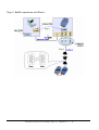
Example 2: Close-Loop Testing
Step 1: Make sure the VxComm Server is working in /m0 mode.
(Please refer to sec. 4.2.3 “Options of command line”)
7188E Series Software User’s Manual, 2004, v2.1, 7MS-003-21 ----- 42
Step 2: Build connection as follows:
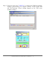
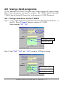
Step 3: Run Send232 and then open PC’s COM1.
7188E Series Software User’s Manual, 2004, v2.1, 7MS-003-21 ----- 43
Step 4: Virtualize 7188E/8000E’s COM1 to become PC’s COM4 by using the
VxComm Utility.
Step 5: Run another Send232 and open PC’s virtual COM4.
Step 6: Type “COM1” in left hand window, and press “Send”.
Data will be sent from PC’s COM1 through Path1 to 7188E/8000E’s
COM1 and immediately returned through Path2 to PC’s COM4.
6.1
6.2
6.3
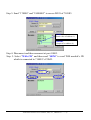
Step 7: Type “Virtual COM” in right hand window, and press “Send”.
Data will be sent from PC’s COM4 through Path2 to 7188E/8000E’s
COM1 and immediately returned through Path1 to PC’s COM1.
7188E Series Software User’s Manual, 2004, v2.1, 7MS-003-21 ----- 44
7.1
7.3
7.2
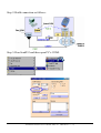
Example 3: External-Devices Testing
Connect 7000 series modules to 7188E/8000E’s COM1. Use VxComm Driver
to virtualize the 7188E/8000E's COM1 to become PC’s COM10. Thus, we can
use the 7000 Utility to search the 7000 series module through COM10.
Note: Users must install the 7000 Utility first by runing
CD-ROM Drive:\Napdos\7000\7000Util\setup.exe
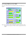
Step 1: Run the 7000 Utility.
7188E Series Software User’s Manual, 2004, v2.1, 7MS-003-21 ----- 45
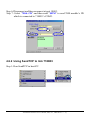
Step 2: Build connection as follows:
7188E Series Software User’s Manual, 2004, v2.1, 7MS-003-21 ----- 46
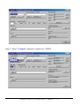
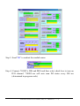
Step 3: Click the menu item "COM Port" to choose the COM port number,
baudrate, and checksum. For example: COM10, 115200, 19200, 9600
and No-Checksum. (These settings depend on the 7000 series
module's settings.)
7188E Series Software User’s Manual, 2004, v2.1, 7MS-003-21 ----- 47
Step 4: Click the
search icon.
Step 5: If the VxComm Driver works well, the 7000 Utility can search the
module(s) connected to the 7188E/8000E’s COM1.
3.6.2
Trouble Shooting
Problem: Client program fail to open the COM port that was created by the
VxComm Driver.
Check:
7188E/8000E's Power supply, Network cable, IP address, subnet-mask and
gateway. (Please refer to the 7188E/8000E user's manual for more
information.)
7188E Series Software User’s Manual, 2004, v2.1, 7MS-003-21 ----- 48
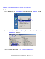
Problem: Client program still fails to open the COM port.
Check:
Step 1: Right click the "My computer" icon and select the "Manage" option.
1
Step 2: Select the "Device Manager" icon from the "Computer
Management" program.
3
2
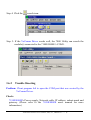
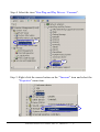
Step 3: Click the menu item "View / Show hidden devices".
7188E Series Software User’s Manual, 2004, v2.1, 7MS-003-21 ----- 49
Step 4: Select the item "Non-Plug and Play Drivers / Ynsernet".
4.1
4.2
Step 5: Right click the mouse button on the "Ynsernet" item and select the
"Properties" menu item.
5
7188E Series Software User’s Manual, 2004, v2.1, 7MS-003-21 ----- 50
Step 6: Check if it shows the message "This device is working properly."
If the driver does not work properly, please remove it and then
re-install and configure it again.
Problem: Client programs open the COM port with success, but fail to access
the device.
Check:
Check the device's power supply and wiring (RS-232: RXD, TXD; RS-485:
D+, D- ; GND).
7188E Series Software User’s Manual, 2004, v2.1, 7MS-003-21 ----- 51
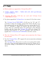
3.7 FAQ
Q: Which modules are supported by VxComm Driver(PC) ?
A: 7188EA, 7188EX, 7188E1 ~ 7188E8, 8430, 8431, 8830 and 8831(after
version 2.0.0 Beta 6).
Q: VxComm Driver(PC) v2.00 does not work with VxComm Server
(7188E/8000E) v2.6.00 ?
A: Yes, please upgrade the VxComm Server to version 2.6.14 or later version.
The VxComm Server(7188E/8000E) v2.6.00 uses the "06" and "07"
command to change the baudrate and the data format and then saves
these configurations into the EEPROM. The newer version adds the "02"
and "03" command to change the baudrate and data format without
saving. These two commands improve the performance when changing
baudrate and data format. The VxComm Driver(PC) also changes the
operation when using the "02" and "03" commands. Thus, users have to
upgrade their VxComm Server(7188E/8000E) to the later version.
Q: Does the VxComm Driver (PC) support auto-reconnection after fixing a
network break?
A: Yes, the VxComm Driver (PC) supports the auto-reconnection mechanism
after version 2.00.
The VxComm Utility allows users to set the server-options that include
Keep-Alive Time (ms) and Connection-Broken time (ms). Please refer to
the section: Adding a 7188E/8000E server and configuring the VxComm
driver.
7188E Series Software User’s Manual, 2004, v2.1, 7MS-003-21 ----- 52
4. Ethernet I/O Applications
4.1 Operation Principle of the Xserver
The typical TCP/IP mechanism is a standard tool but very complicated for
a software engineer. It takes long time for a software engineer to develop a
programs using TCP/IP protocol.
The command protocol designed for a TCP/IP system can be based on
user’s applications without any limitations. So every software engineer can
design his special protocol without any pre-defined standard. This will cause
some of the troubles given as follows:
z
z
z
z
z
Is this protocol reliable?
Does this protocol fit all requirements?
How to maintain protocol created by another software engineer?
Time to market?
Engineering cost to design & debug this protocol?
The Xserver is designed to solve all problems mentioned above as follows:
¾ We design & maintain the reliable, original Xserver for all users.
¾ The protocol is designed to fit all requirements of the 7188E series.
¾ The protocol is OPEN & expandable to reduce user’s design cost.
¾ An easy-use interface is designed for user’s special applications.
¾ Standard design and maintaince for all engineers using this protocol.
The features of the Xserver are given as follows:
¾ The Xserver, VComNNNN.EXE, is an embedded firmware designed for
the 7188E series in the default shipping
¾ Supports Virtual COM applications
¾ Supports Ethernet I/O applications
¾ Supports I/O expansion bus
¾ Supports 7188E1/2/3/4/5/8, 7188EX & 7188EA and etc.
¾ TCP/IP protocol & command protocol is open & expandable.
¾ Provides easy-use interface for user’s special programs.
With the help of Xserver, a software engineer can design a robust Xserver
in one day. We will provide about 50 ~ 100 typical real world applications for
user’s reference. From these demos, a software engineer can start easily with a
cost-friendly time to market. Refer to Sec. 4.3 for more information.
7188E Series Software User’s Manual, 2004, v2.1, 7MS-003-21 ----- 53
4.2 Command Protocol of Xserver
4.2.1 IP and port configuration
Before developing Ethernet I/O applications for your PC, you must first know
the IP address and the Ethernet port number. The 7188E/8000E and all COM
ports of the 7188E/8000E use the same IP address, but different Ethernet port
number. They are listed below:
Function
Modbus TCP
Virtual 7000
(I/O boards)
7188E/8000E configuration
COM1 of the 7188E/8000E
COM2 of the 7188E
COM3 of the 7188E/8000E
COM4 of the 7188E/8000E
COM5 of the 7188E
COM6 of the 7188E
COM7 of the 7188E
COM8 of the 7188E
IP address
192.168.255.1
192.168.255.1
Port number
502
9999
192.168.255.1
192.168.255.1
192.168.255.1
192.168.255.1
192.168.255.1
192.168.255.1
192.168.255.1
192.168.255.1
192.168.255.1
10000
10001
10002
10003
10004
10005
10006
10007
10008
192.168.255.1 is the default IP address of the 7188E/8000E. You can change
the IP address to suit your requirements. Contrary to the IP address, the
Ethernet port is fixed. You must use the port number as defined above.
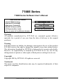
4.2.2 Command set of the Xserver
Cmd Explain
Instruction Format
Example:
Example:
Sends to Xserver Receives from Xserver
01
<01>
01
V2.6.14[10/04/2001]
<02,Port(1),Baud>
02138400
OK
<03,Port(1),LineControll(3)>
0328N1
OK
0414
141(First asking from client)
14 after system reset)
140(Not first asking from
client 14 after system reset)
02
03
04
Version
Sets baudrate
(Doesn’t store the
setting to EEPROM)
Sets data format
(doesn’t store the
setting to EEPROM)
Gets system reset
status
<04,Client(2)>
7188E Series Software User’s Manual, 2004, v2.1, 7MS-003-21 ----- 54
05
06
07
08
09
10
11
12
13
14
15
16
17
18
19
RTS
Sets baudrate
(Stores the setting to
EEPROM)
Sets data format
(Stores the setting to
EEPROM)
Sets IP
Received Timeout
(Modified from
Vcom3008)
Server Name
Diag
Sets Gateway
Gets Gateway
Sets Mask
Gets Mask
Gets COM Status
Digital Input
Digital Output
Bypass User Defined
Command
<05,Port(1),Set(1)>
1:On 0:Off
0511
OK(COM Port RTS on)
<06,Port(1),Baud>
06138400
OK
<07,Port(1),LineControll(3)
0728N1
OK
<08,IP(12)>
<09,Port(1),ttttt>
Port:1~8
ttttt: 0~99999, unit ms.
If set as ‘a’, ‘A’ or -1 the ttttt is
Decided by system.
<10>
<11,String(<=80)>
<12,GatewayIP(12)>
<13>
<14,Mask(12)>
<15>
<16,Port(1)>
<17,Addr_Hex(4)>
<18,Addr_Hex(4),Data_Hex(2)>
08192168255001
OK. Reconnect
093
0910020
30
120
10
11Hello
12192168000001
13
14255255000000
15
161
1703f8
1803f855
7188E2
Hello
OK. Reconnect
192.168.0.1
OK. Reconnect
255.255.0.0
9600,8,N,1
F8
OK
<19,Command>
19(User defined)
(User defined)
201
OK (Enable 5 Digital LED
show information)
20
Enables
5 DigitLED
<20,Enable(1)>
1:Enable 5DigitLed
0:Disable 5DigitLed
21
Gets Mac
<21>
22
23
Gets MiniOS Version
Calls VcomUserCmd
Sets feedback
command No.
<22>
<23,String>
24
25
<24,Enable(1)>
00:80:30:39:9f:e2
xx: Hexadecimal value
22
v2.0.1(2003/8/22)
23(User definded) (User defined)
240
OK
241
24OK
21
<25,m>
m='S': Inquire the timeout value of
system (/ST)
m='W': Inquire the timeout value of
socket (/W)
m='N': Inquire the Max number of
socket
m='M': Inquire the Work option:/M0
or /M1
m='B': Enable/Disable the
Broadcast mode
B1:Enable Broadcast
Inquires the parameter
25M
mode, B0: Disable
or system.
Broadcast mode
(Default:B0)
m='E': Inquire the command echo
mode, E1:Enable echo
mode, E0: Disable echo
mode (Default:E0)
m='L': Inquire the 7-SEG LED
status, L1: Enable LED to
show, L0: Disable LED to
show. (Default:L1)
m='I': Inquire the
NAME/IP/MASK/GATEWAY/MAC
M0
7188E Series Software User’s Manual, 2004, v2.1, 7MS-003-21 ----- 55
of 7188E
<26,mn>
m='M': set the work option /M (n:0
n:1)
m='B': Set the Broadcast mode.
("26B0") ("26B1")
m="S": Set the system TIMEOUT
/ST ("26S300)
m="W": Set the socket TIMEOUT
/W ("26W86400000")
m="I": Set IP, MASK, GATEWAY,
or MAC
(IP/GATEWAY/MASK/MAC must
be UPPERCASE)
<27,Port(1), Set(1)>
26
Sets the system
parameter
27
Sends Break signal to
COM Port of
7188E/8000E
Port 1~8
Set:1 Break enable
0 Break Disable
<28,Port(1), m,n>
26M0
OK
2711
2710
OK
OK
28111
111
281
111
Port:Only support COM1/3/4/5
28
29
30
31
32
34
M: Set the CTS mode
N: Set the RTS mode
0: Disable
1: Enable
(RTS must control by users
Program)
2: Enable, auto control by
Hardware.
3: Enable, auto control by
Software library.
Sets/Inquires the
CTS/RTS mode of
the flow control
For CTS, mode ‘1’ and mode ‘3’ are
same.
If the command doesn’t add the mn
arguments, the turn value is the
previous value of the
First once.
<29,Port(1)>
291
COM port (Only support
COM1/3/4/5)
Inquires the
CTS status
Sends the string and
receives the data which
is the same as the
string of Sending
Set the trigger level of
COM port of 16550
(Support COM3~8 only,
It didn’t support
COM1~2)
Set the trigger level of
COM port buffer
(Bytes).
Reads the library
version and date of
Vcomnnn.exe(Include
7188el.lib & tcpipl.lib)
CTS1=0
<30, String>
30123456789
String: Any string (The max length
of string is 1460 bytes)
30
30123456789
<31,Port(1),[LL]>
Port: 3~8
[LL],”1”,”4”,”8”,”14”
Choice one only from four items.
313
314
(COM3, triggerlevel = 14)
38
(COM3, triggerlevel = 8)
321
322
11460
21460
34
7188el.lib Ver. 2.1[Aug 02
2004],
tcpipL.lib Ver. 1.3[Apr 08
2004]
(32,Port(1),[nnnn]>
Port: COM port 1~8
Nnnn:”0”~”1460”
<34>
31314
30
7188E Series Software User’s Manual, 2004, v2.1, 7MS-003-21 ----- 56
Note 1: The number inside () of instruction format is parameter size (byte).
Note 2: Don’t insert any space between parameters (except user defined
command).
Note 3: All command (except user defined command) responses will add a
terminal char CR (0x0d).
Note 4: Refer to vxcomm.htm to get more information about Xserver
command protocol and parameter setting in 7188e\Tcp\Vxcomm\Doc\
7188E Series Software User’s Manual, 2004, v2.1, 7MS-003-21 ----- 57
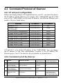
4.2.3 Options of command line
Command Line Options
VcomNNNN.exe [/Option] (NNNN denotes the Vxcomm.Lib version)
Options
Explanations
/1
Recognizes 7188E1
/2
Recognizes 7188E2
/3
Recognizes 7188E3
v3.0.0 and above
/4
Recognizes 7188E4
v3.0.0 and above
/5
Recognizes 7188E5
v3.0.0 and above
/8
Recognizes 7188E8
v3.0.0 and above
/X
Recognizes 7188EX
v3.0.0 and above
/A
Recognizes 7188EA
v3.0.0 and above
/M0
Notes
Multi-echo mode.
Echoes data from the 7188E/8000E COM
ports to each client connected to the
7188E/8000E.
(It’s the default mode in 7188E firmware)
/M1
Single-echo mode.
Echoes data from the 7188E/8000E COM
ports to the specific client requested the
service.
(It’s default mode in the Xserver program)
/Wxxx
Sets the timeout value for building a socket
connection. If the timeout expires,
Vxcomm.exe/Xserver releases the
connection.
xxx: timeout
Time unit: sec
Default: 0
xxx=0: disables option /W
/STxxx
Sets the system timeout value between two
packets sent from the network to
7188E/8000E. If the timeout expires,
Vxcomm.exe/Xserver will automatically
v2.6.12 and above
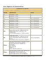
7188E Series Software User’s Manual, 2004, v2.1, 7MS-003-21 ----- 58
reboot system itself.
XXX: timeout
Time unit: sec
Default: 0
xxx=0: disable option /ST
/Txxx
Sets a timeout value for the interval
between the completion of a command
being sent from the 7188E/8000E to the
COM ports, and the start of the data being
received from the COM port If the timeout
expires, Vxcomm.exe/Xserver gives up this
data.
Time unit: ms
Default: 100 ms
xxx=0: disable option /T
Acts in M1 (Singleecho mode)
Sets the CTS control mode.
/FCnnnnn
nnnnn depends on the setting value and
represents COM1-5 respectively.
v3.0.07 and above
n:0~3 please refer to parameters of
command "28" for more details.
Sets the RTS control mode
nnnnn depends on the setting value and
/FRnnnnn represents COM1-5 respectively.
v3.0.07 and above
n:0~3 please refer to parameters of
command "28" for more details
Sets the terminal character.
When the last character of the receiving
data matches the terminal character, the
receiving data will be returned immediately.
/Ehh
hh is a hexadecimal value, The default
value is 0
v3.0.09 and above
EX:0x0A is set as "/E0A"
0xFF is set as "/EFF", 0 denotes no
terminal character.
/Pxxxxx
Changes the command port (default is
10000). If Command Port 10000 is changed v3.0.09 [07/23/2003]
to 200, the TCP/IP mapped COM port will be or later
201~208.
7188E Series Software User’s Manual, 2004, v2.1, 7MS-003-21 ----- 59
/S1
/L0
The Command port and each TCP/IP
mapped COM port only allows one TCP/IP
connection, Other connection will not be
accepted.
Adds the "/L0" command to the command
line,allowing LED5 to be disabled/enabled..
It economizes the running time for no
5DigitLed modules)
v3.0.09[10/29/2003]
or later
v3.0.09 or later
/Zxxx
This command is used to set ACK delay
time. [2004/04/19] Defalut:1000 ms
3.2.0[03/24/2004] or
later
/Y
The command is used for 8KE4/8KE8
module.
3.2.0[2004/04/19] or
later
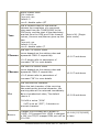
/M0: Multi-echo mode
Condition 1: One client sends a request to Xserver to access devices. The
Xserver echoes data from devices to every client which is
connected to the 7188E/8000E.
7188E Series Software User’s Manual, 2004, v2.1, 7MS-003-21 ----- 60
Condition 2: No clients send a request to Xserver to access devices. The
Xserver echoes data from devices to every client which are
connected to the 7188E/8000E.
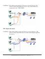
/M1: Single-echo mode
Condition 1: One client sends a request to Xserver to access devices. The
Xserver echoes data from devices to the client which requested
the service.
7188E Series Software User’s Manual, 2004, v2.1, 7MS-003-21 ----- 61
Condition 2: No clients send any request to Xserver to access devices. The
Xserver doesn’t echo data from devices to any client.
/Txxx:
7188E Series Software User’s Manual, 2004, v2.1, 7MS-003-21 ----- 62
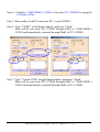
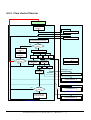
4.2.4 Flow chart of Xserver
Reset 7188E/8000E
Xserver
Initialize
UserInit(void)
UserLoopFun(void)
Scan COM ports &
Send packet from TCP ports
New packet
ready ?
No
Yes
Update
5 DigitLED
Switch case TCP port
Refresh hardware
Watchdog
Yes
Receive packet
Timeout ?
10000 + N
10000
9999
502
Timer Trigger
Bypass packet to
COM port N
Switch case
command
UserCount(void)
No
Other
23
19
Cmd(Without "19")
Execute
command
Response
UserCmd(Cmd,Response)
VcomUserBinaryCmd
(TCPREADDATA *p)
User.c
No
Send data
to client ?
Yes
Send packet from
TCP port 10000
VcomCmdModbus
(TCPREADDATA *p)
vModbus.c
VcomCmd7000
(TCPREADDATA *p)
VxComm.lib
7188E Series Software User’s Manual, 2004, v2.1, 7MS-003-21 ----- 63
v7000.c
It is very difficult to develop an embedded controller program with
Ethernet/Internet communication. But by using the Xserver, users can do that
quickly and easily. Users need only modify 7 functions in User.c, vModbus and
v7000.c. Users build their own code in the 7 functions to make the Xserver
work as they desire. The features of the 7 functions are listed below:
¾ UserInit (void):
Xserver executes this function once as soon as the 7188E/8000E is turned
on. Therefore all variables of initial values or initial status must be set in
this function.
¾ UserLoopFun (void):
Xserver executes this function every scan loop. One Xserver scan loop
completes in a short time, so real time work should be executed by this
function. See Demo12.
¾ UserCount (void):
This function will be triggered when the time interval, set in
AddUserTimerFunction, is up. For best result, call AddUserTimerFunction
in UserInit to let the Xserver call the UserCount period. Longest time
interval is 65.535 seconds (2^16–1 ms). See Demo9.
¾ UserCmd (Cmd, Response):
Xserver executes this function when client program sends the command
“19” to port 10000 of the Xserver. This command is defined in UserCmd
function by users. When the Xserver receives packets from port 10000, the
Xserver checks the data. If the data begins with “19”, the Xserver trims
“19” and passes the other data (not including “19”) to be the first parameter
Cmd of function UserCmd.
User can define his own command protocol in UserCmd. For example,
define <19,Read/Write(1),address(4),[value(2)]> to replace command 17
and 18, then one can send “19R03f8” to read values form address 03f8;
sends “19W03f85a” to write 5a to address 03f8.
Users can decide whether or not any other characters are needed between
parameters. Any command protocol format will be accepted, because it is
user defined.
At the end of UserCmd, copy the results to the second parameter Response
7188E Series Software User’s Manual, 2004, v2.1, 7MS-003-21 ----- 64
Then the XServer will send the string to the Client program by port 10000.
See Demo4.
¾ VcomUserBinaryCmd (TCPREADDATA *p):
Xserver executes this function when client program sends command “23”
to port 1000 of the Xserver. This function is similar to UserCmd. When the
client program sends command “23”, VcomUserCmd will receive
TCPREADDATA type information. The TCPREADDATA is declared as
below:
Type define t_TcpReadData{
Int Comport;
int Socket;
int Length;
char* ReadUartChar;
} TCPREADDATA;
p->ReadUartChar: the buffer where command data is stored(include “23”)
p->Length: the command data length (include “23”)
p-Socket: the Xserver assigns a socket number to index when client sends
command “23” to the 7188E. So, the socket number can used to return
messages to a specific client. Send message to specific client, and call
VcomSendSocket (int skt, char * data, int cnt). The first parameter should
be the socket number. See Demo23.
¾ VcomCmdModbus (TCPREADDATA *p):
Xserver executes this function when client program sends commands to
port 502 of the Xserver. This function is used to implement Modbus TCP
protocol to access devices. See Demo27.
¾ VcomCmd7000 (TCPREADDATA *p):
Xserver executes this function when client program sends commands to
port 999 of the Xserver. This function is used to implement 7000 seriescompatiable commands to access expansion boards.
See 7188e\TCP\Xserver\v7000\*.*
7188E Series Software User’s Manual, 2004, v2.1, 7MS-003-21 ----- 65
4.3 Demo program list of Xserver
After developing the Xserver program, users must download the program into
the 7188E/8000E and execute one client program to test if all functions run
properly.
Demo
Function
Explanation
Demo4
Echoes command
(Original
string
X-Server)
Client
Client1
Demo5
Echoes special
string to clients
Demo6
(7E only)
Reads/writes the I/O This demo shows how to use command
port of the 7188E
19 to replace command 17, 18
Client1
Uses printCom1 to
debug programs
You can use "Print" or "printCom1" to
send a Debug string to PC monitor by
7188E/8000E's COM1.
If you want to use "Print", you must use
"DisableCom" and "RestoreCom" to
disable "printCom1".
Client1
Uses Print to debug
programs
You can use "Print" or "printCom1" to
send a Debug string to PC monitor by
7188E/8000E's COM1.
If you want to use "Print", you must use
"DisableCom" and "RestoreCom" to
disable "printCom1".
Client1
Demo9
Timer trigger demo
UserCount will be executed every
second. Count value will be icreased in
UserCount. PC can read count value to
know how many seconds after count
value be cleared.
Client1
Demo10
Refreshes
Watchdog demo
If user's function cost more than 1.6
seconds. User must insert RefreshWDT
Client1
Demo7
Demo8
Xserver will echo "7188_Series." or
"8000_Series." to clients.
7188E Series Software User’s Manual, 2004, v2.1, 7MS-003-21 ----- 66
Client1
function to refresh WDT avoid the OS
restarting itself in 1.6 second.
Demo11
(7E only)
Real- time I/O
controlling
This demo shows complex real time
DI/DO operation in UserLoopFun.
Client1
Demo12
Scan-time
evaluation
UserLoopFun will increase count value
every scan loop. PC can read how many
scan loops there are after clear count
value. So user can use this demo to test
Xserver performance.
Client2
Demo13
(7E only)
Pulse width
measurement
LoopFun reads the D/I signal. If signal is
changed, records time ticks and
calculates signal width.
Client1
Demo14
Controls 7-SEG
LED
Show5DigitLed, Show5DigitLedWithDot
can show 5 digits to 7-SEG LEDs
The two functions can show '0' ~ '9'
'a' ~ 'f'
'A' ~ 'F'
' ', '-', '.'
Client4
Demo15
(7E only)
Reads channel
values from
7017/7018
This demo shows how to send command
to read channel value from 7017 or 7108
which is connected to 7188E's COM2.
Client4
Demo17
(7E only)
Pulse width
measurement
This demo is similar to demo13 and
detects signal change and measures
signal width.
Client5
Demo18
Reads I-7000 series
module's ID
This demo shows how to communication
with the 7000 series which are connected Client4
to COM2 of 7188E or COM3 of 8000E.
Reads 64 bits
unique hardware
serial number
Unique serial number is used to protect
user's software. Using 7188xw.exe to
enter 7188E, MiniOS7 will show a
number. User can check the number at
first, then decide to execute Xserver from
the point on.
Demo19
7188E Series Software User’s Manual, 2004, v2.1, 7MS-003-21 ----- 67
Client4
Demo20
NVRAM's characteristic is short response
Reads/Writes/Clears
time, limitless erasure and the battery
Client4
NVRAM
backup for 10 years.
Demo21
Controls hardware
in UserCount
Actions concerning hardware control in
UserCount is prohibited. If user want to
control hardware in UserCount, they
must use flag variable to pass the
command to UserLoopFun. Function of
hardware can be executed correctly in
UserInit, UserLoopFun, UserCmd. This
demo will increase numbers every
second and show the value to LEDs in
UserCount function.
*Demo22
(7E only)
Data Acquisition &
Compression &
Averaging
ODM for Contec company
CheckValue
Uses VcomSendSocket to echo all data
(including "23") to specific clients.
Client4
Echoes all data
**Demo23 (including "23") to
specific clients.
Demo24
Uses countdown
timer
*Demo25
(7E only)
Data Acquisition,
Compression, &
Averaging
Demo27
(7E only)
Client4
There are 8 countdown timer (channel 0
to channel 7). This demo uses channel 0.
The countdown timer initial value is 1000
None
ms. When the countdown timer value
become 0, the value of the LED will
increase.
CheckValue
Uses Modbus TCP
protocol to D/I/O
We will provide 50 ~100 demo programs for the Xserver in the future.
Please refer to 7188E\TCP\Xserver\Xserver.htm and Function.htm for more
information of demo programs.
7188E Series Software User’s Manual, 2004, v2.1, 7MS-003-21 ----- 68
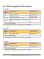
4.4 Client program list for Xserver
z 7188E2
Client
programs
Explanation
Special Demo
Config
Host Configuration
All simple demos
E2
Full features demo
All simple demos
SendCmd
Sends command/data to 7188E2
All simple demos
SendCom
Sends command/data to 7188E2's COM
port
..... More client programs
Client programs are located at 7188e\TCP\Xserver\7188E2
z 7188E3
Client
Explanation
programs
Special Demo
7188E3
All simple demos
Full features demo
..... More client programs
Client programs are located at 7188e\TCP\Xserver\7188E3
z 7188E4
Client
Explanation
programs
Special Demo
7188E4
All simple demos
Full features demo
..... More client programs
Client programs are located at 7188e\TCP\Xserver\7188E4
7188E Series Software User’s Manual, 2004, v2.1, 7MS-003-21 ----- 69
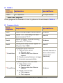
z 7188EA
Client
Explanation
programs
Special Demo
7188EA
All simple demos
D/I/O operation
..... More client programs
Client programs are located at 7188e\ Tcp\Xserver\Client\Module\7188EA
z Common clients
Client
programs
Explanation
Special Demo
Client1
Used to test all simple Xserver demos
All demos
Client2
Sends "19 0", then delay n ms and
send command "19 1".
Demo12
Client4
Similar to Client1, just adds sending
string with "CR" function.
All demos
Client5
Sends period step function signals to
I/O port of the 7188E.
Demo17
CheckValue main functions:
1. Catches below errors:
a. Winsock error
***CheckValue
b. Receive data from Xserver
timeout
2. Checks received data out of range
3. Automatic reconnect ability.
Demo22, Demo25 or
demos which return
value (total 7
characters)
CheckString with main functions:
1. Catch below errors:
a. Winsock error
b. Receive data from Xserver
***CheckString
timeout
2. Check received data
a. Full compare
b. Part compare
All demos
7188E Series Software User’s Manual, 2004, v2.1, 7MS-003-21 ----- 70
3. Automaticly reconnect ability.
***GetString
GetString with main functions:
1. Catch below errors:
a. Winsock error
b. Receive data from Xserver
timeout
2. Automaticly reconnect ability.
3. Large text box can show 1600
bytes at one page.
All demos
..... More client programs
Common client programs are located at 7188e\TCP\Xserver\Client
Note:
¾ You can run all 7188E special clients (7188E2, 7188E3, 7188E4, 7188EA,
etc.) from 7188e\Tcp\Xserver\Client\Module.
¾ You can install all common clients (Client1, Client2, Client4, Client5,
CheckValue, CheckString, GetString, etc.) by executing
\7188e\Tcp\Xserver\Client\Common\Setup\Setup.exe.
¾ Please refer to 7188E\TCP\Xserver\Xserver.htm and Function.htm for
more information of demo programs.
7188E Series Software User’s Manual, 2004, v2.1, 7MS-003-21 ----- 71
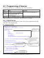
4.5 Programming of Xserver
To develop the Xserver, you must have the 9 files listed below:
Item
Files
Location
Head file
7188E.h, TCPIP.h, Vxcomm.h
7188E\TCP\Xserver\Demo\BC\Lib
Library
7188EL.Lib, TCPIPL.Lib,
VcomNNNN.Lib
User’s file User.c, vModbus.c, V7000.c
7188E\TCP\Xserver\Demo\BC\Demo4
Note: The NNNN of VcomNNNN.Lib is the lib file’s version.
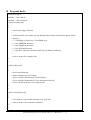
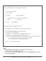
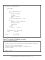
4.5.1 Original Xserver
All user.c files are devided into two parts. One is the explanation head, the
other one is the program body.
z Explanation head:
/* DEMO4: Echoes command string
Compiler: BC++ 3.1 ,TC++ 3.0, TC++ 1.01, TC 2.0
Compile mode: large
Project: user.c
v7000.c
vModbus.c
[after Vcom_3002]
..\Lib\7188EL.Lib
..\Lib\TCPIPL.Lib
..\Lib\VcomNNNN.Lib, with NNNN being the lib file's version.
19~!@#$ -> Any non-null command will be accepted.
This demo is the original user.c
User can modify their own Xserver from this file.
Hardware: 7188E
Some addition hardware
devices will listed here.
Content of the
project file.
Client programs use this
command protocol to
communicate with the
Xserver.
Explanation of this demo
program.
Refer 7188e\TCP\Doc\[Big5|Eng|Gb2312]\Vxcomm.htm
7188e\TCP\Xserver\Xserver.htm
7188e\TCP\Xserver\Function.htm
to get more information.
Last modified date.
[17/Nov/2001] by TCK
7188E Series Software User’s Manual, 2004, v2.1, 7MS-003-21 ----- 72
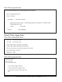
z Program body:
#include<string.h>
#include "..\lib\7188e.h"
#include "..\lib\vxcomm.h"
void UserCount(void)
{
/*
// user's timer trigger function
//
// In this function, user cannot use any function that will use the hardware signal "clock",
// Such as:
// 1. ClockHigh(),ClockLow(), ClockHighLow(),
// 2. Any EEPROM functions.
// 3. Any 5DigitLed functions.
// 4. Any NVRAM function.
// 5. Any RTC function.(GetTime(),SetTime(),GetDate(),SetDate())
//
// refer to demo9 for example code
*/
}
void UserInit(void)
{
/*
// user's initial function
// timer initialized for UserCount()
// I/O or variables initialized for UserLoopFun()
// I/O or variables initialized for User's functions in this file
// refer to demo9 & demo11 for example code
*/
}
void UserLoopFun(void)
{
/*
// VxComm.exe will call this function every scan time
// refer to demo11 for scan-time evaluation
*/
}
7188E Series Software User’s Manual, 2004, v2.1, 7MS-003-21 ----- 73
int UserCmd(unsigned char *Cmd,unsigned char *Response)
{
/*
// user's command interpreter
// refer to all demo
*/
if (Cmd[0])
/* Not Null command */
{
strcpy(Response,Cmd); /* echo user's command back */
return 1;
/* return OK */
}
return 0;
/* return ERROR */
}
int VcomUserBinaryCmd(TCPREADDATA *p)
{
/* VXCOMM.EXE 2.6.12(09/04/2001) or later will support this function.
TCP PORT 10000, command 23 will call this function.
user can get the following message:
p->ReadUartChar : the buffer store the command data(include "23")
p->Length : the command data length(include the two byte "23")
p->Socket : the socket number that receives the command, that is, when the user function wants
to return a message to the client, just use the socket to send data.
use: VcomSendSocket(p->Socket,pdata,datalength);
*/
return 1; /* any value will be accept */
}
Note:
¾ We will enhance the Xserver continually. Please refer to
7188E\Document\Readme.htm and
¾ 7188e\TCP\Vxcomm\Doc\[Big5|Eng|Gb2312]\Vxcomm.htm to get new
version information.
7188E Series Software User’s Manual, 2004, v2.1, 7MS-003-21 ----- 74
4.5.2 Setting of compiler (BC++ 3.1)
To develop programs for 7188/7188X/7188E/8000 series, you can use the
compilers below:
1.
2.
3.
4.
5.
BC++ 3.1~5.02
MSC
MSVC (before version 1.52)
TC 2.01
TC++ 1.01
From Borland’s web site, you can download the free TC 2.01 and TC++ 1.01
compilers.
Web site: http://community.borland.com/museum/
How to use BC++ 3.1’s IDE to compile projects? Please follow the steps below:
Step 1: Create a new project.
1.1
1.2
1.3
7188E Series Software User’s Manual, 2004, v2.1, 7MS-003-21 ----- 75
1.4
Step 2: Add all necessary files into the project.
2.1
2.2
Step 3: Set Code generation options.
3.1
3.2
7188E Series Software User’s Manual, 2004, v2.1, 7MS-003-21 ----- 76
Step 4: Set Advanced code generation options.
4.1
4.2
4.4
4.3
Step 5: Set Debugger options.
5.1
5.2
7188E Series Software User’s Manual, 2004, v2.1, 7MS-003-21 ----- 77
Step 6: Make the project.
6
Note:
Please refer to 7188e\Document\TCPLib.pdf to get more information
about settings of other compilers.
7188E Series Software User’s Manual, 2004, v2.1, 7MS-003-21 ----- 78
4.6 Using client programs
To test functions of Xserver, you must run a client program. We support many
Quick Start documents for specific modules, like 7188E3_Quick_Start.pdf,
7188E4_Quick_Start.pdf. Please refer to documents in 7188E\Document.
4.6.1 Using Client4.exe to link 7188E3
Step 1: Run 7188e\Tcp\Xserver\Client\Common\VB5\Client4\Client4.exe in
host-PC. Press “Connect” button to connect to 7188E3.
Send command “01”, “10”.
01 (Firmware version)
10 (Module name)
Step 2: Send “161”, “162” and “163” to readout COM port setting.
161 (Setting of COM1 )
162 (Setting of COM2 )
163 (Setting of COM3 )
7188E Series Software User’s Manual, 2004, v2.1, 7MS-003-21 ----- 79
Step 3: Send “170000” and “18000005” to access D/I/O of 7188E3.
170000
(Read value of address 0 )
18000005
(Output 05 to address 0 )
Step 4: Disconnect and then reconnect at port 10002.
Step 5: Select “With CR” and then send “$02M” to read 7000 module’s ID
which is connected to 7188E3’s COM2.
1
3
2
7188E Series Software User’s Manual, 2004, v2.1, 7MS-003-21 ----- 80
Step 6: Disconnect and then reconnect at port 10003.
Step 7: Select “With CR” and then send “$03M” to read 7000 module’s ID
which is connected to 7188E3’s COM3.
1
3
2
4.6.2 Using SendTCP to link 7188E3
Step 1: Run SendTCP in host-PC.
7188E Series Software User’s Manual, 2004, v2.1, 7MS-003-21 ----- 81
Step 2: Press “Connect” button to connect to 7188E3.
7188E Series Software User’s Manual, 2004, v2.1, 7MS-003-21 ----- 82
Step 3: Send command “10” to 7188E3.
Step 4: Select “Port 2” and “CR”. Then send “$02M” to read 7000 module’s
ID which is connected to 7188E3’s COM2. If you enable 7000
module’s checksum function, select “CS_CR”. The “CS_CR” option
will add two checksum bytes, then adds “CR”.
2
1
2
3
7188E Series Software User’s Manual, 2004, v2.1, 7MS-003-21 ----- 83
If you want to change the 7188E’s COM ports settings, click “Set” to change
them. The 7188E’s COM port that you want to configure is specified by
“Select Port” combo list. Port 2 means you want to configure the 7188E’s
COM2.
1
3
2
Please refer to SendTCP’s help document for more information.
7188E Series Software User’s Manual, 2004, v2.1, 7MS-003-21 ----- 84
4.6.3 Using 7188E3.exe to link 7188E3
Step 1: Run 7188e\Tcp\Xserver\Client\Module\7188e3\Vb5\7188E3.exe in
host-PC.
Step2: Press “Connect” button, and then the program will readout relative
information concerning the 7188E3 and start scanning the DI of the
7188E3.
7188E Series Software User’s Manual, 2004, v2.1, 7MS-003-21 ----- 85
Step 3: Send “10” to readout the module name.
Step 4: Connect 7188E3’s DI0 and DO0 and then select check box to turn on
D/O channel. 7188E3.exe will auto scan D/I status every 500 ms
(determined in program code).
7188E Series Software User’s Manual, 2004, v2.1, 7MS-003-21 ----- 86
Turn on DO0
DI0 is low
D/I status by hex number
(only lower 4 bits are valid)
Step 5: Send “$02M” to read 7000 module’s ID which is connected to
7188E3’s COM2.
Step 6: Send “$03M” to read 7000 module’s ID which is connected to
7188E3’s COM3.
7188E Series Software User’s Manual, 2004, v2.1, 7MS-003-21 ----- 87
4.7 Demo Programs of Xserver
Demo5: Echoes special string to clients
Part of the program body:
int UserCmd(unsigned char *Cmd,unsigned char *Response)
{
// user's command interpreter
// refer to all demo
strcpy(Response,"7188_Series."); // return “7188_Series.” string to clients
return 1;
// return OK
}
Demo6: Reads/writes the I/O port of 7188E
Part of the explanation head:
// 19i n, 19I n
-> read D/I value (hex) from address n(hex)
// 19o add val, 19O add val -> output D/O value (hex) to address n(hex)
// 19 o add val, 19 O add val
// This demo shows how to use command 19 to replace command 17, 18
// Hardware: [7188EA] or [7188EX + D/I/O expansion board]
//
Note: Base address of 7188EA's DI is 1.
Part of the program body:
char cAddr[80],cVal[80];
int UserCmd(unsigned char *Cmd,unsigned char *Response)
{
// user's command interpreter
// refer to all demo
int j,iVal,iAddr;
7188E Series Software User’s Manual, 2004, v2.1, 7MS-003-21 ----- 88
if (Cmd[0]) // Not Null command
{
switch(Cmd[0])
{
case 'i': // inp command: i 0 or I0
case 'I':
sscanf(Cmd+1,"%x",&j);
iVal=inp(j);
sprintf(cVal,"%x",iVal);
break;
case 'o': // outp command: O0 5A or o 0 AB
case 'O':
sscanf(Cmd+1,"%x %x",&iAddr,&iVal);
sprintf(cVal,"%x",iVal);
outp(iAddr,iVal);
break;
default:
return 0;
// return error
};
strcpy(Response,cVal); // return I/O value
return 1;
// return OK
}
return 0;
// return ERROR
}
Demo7: Uses printCom1 to debug programs
Part of the explanation head:
// 19~!@#$ -> Any non-null command will be accepted.
// You can use "Print" or "printCom1" to send Debug string to PC monitor by 7188E's COM1.
// "printCom1" is the defualt function of Xserver.
// If you want use "Print", you must use "DisableCom" and “RestoreCom”
// to disable "printCOM1".
// Hardware: [7188E]
7188E Series Software User’s Manual, 2004, v2.1, 7MS-003-21 ----- 89
Part of the program body:
int UserCmd(unsigned char *Cmd,unsigned char *Response)
{
// user's command interpreter
// refer to all demo
if (Cmd[0]) // Not Null command
{
printCom1("%s\n\r",Cmd); // Send debug string to PC monitor by 7188E's COM1
strcpy(Response,Cmd);
return 1;
// return OK
}
return 0;
// return ERROR
}
Demo9: Timer trigger demo
Part of the explanation head:
// 19c, 19C -> clear count value
// 19r, 19R -> read count value
//
//
//
//
UserCount will be executed every second.
Count value will be increased in UserCount.
PC can read count value to know number of seconds
after count value is cleared.
// Hardware: 7188E
Part of the program body:
unsigned int cnt;
char c_cnt[20];
void UserCount(void)
{
// user's timer trigger function
// refer to demo9 for example code
// printCom1("\n\rUserCount %d",cnt);
cnt++;
}
7188E Series Software User’s Manual, 2004, v2.1, 7MS-003-21 ----- 90
void UserInit(void)
{
// user's initial function
// timer initialized for UserCount()
// I/O or variables initialized for UserLoopFun()
// I/O or variables initialized for User's functions in this file
// refer to demo9 & demo11 for example code
cnt=0;
AddUserTimerFunction(UserCount,1000); // call UserCnt every 1000 ms
}
int UserCmd(unsigned char *Cmd,unsigned char *Response)
{
// user's command interpreter
// refer to all demo
int i;
if (Cmd[0])
// Not Null command
{
switch(Cmd[0])
{
case 'c':
// 19c, 19C --> clear count
case 'C':
cnt=0;
break;
case 'r':
// 19r, 19R --> read count
case 'R':
break;
default:
return 0; // Command Error
}
sprintf(c_cnt,"%d",cnt);
strcpy(Response,c_cnt); // return count value
return 1;
// return OK
}
return 0;
// return ERROR
}
7188E Series Software User’s Manual, 2004, v2.1, 7MS-003-21 ----- 91
Demo11: Real-time I/O control
Part of the explanation head:
// 19i, 19I -> read D/I form address 0
// 19o, 19O -> D/O to address 0
// This demo show complex real time DI/DO operation in UserLoopFun
// Hardware: [7188EA] or [7188E + D/I/O expansion board]
//
Note: Base address of 7188EA's DI is 1.
Part of the program body:
unsigned char DI,DO;
char cVal[80];
void UserLoopFun(void)
{
// VxComm.exe will call this function in every scan time
// real-time I/O control function
// DO0=!DI0, DO1=(DI1+DI2), DO2=(DI3)
// DO3 ~ DO6: control by host-pC
DI=inportb(0);
// read DI
if (DI&1) DO=DO&0xfe;
else DO=DO | 1;
// DO0=!DI0
if ((DI&2) || (DI&4)) DO=DO | 2;
else DO=DO & 0xfd;
// DO1=(DI1+DI2)
if (DI&8) DO=DO | 4;
else DO=DO & 0xfb;
// DO2=DI3
outportb(0,DO);
// write to DO0, DO1, DO2
}
7188E Series Software User’s Manual, 2004, v2.1, 7MS-003-21 ----- 92
int UserCmd(unsigned char *Cmd,unsigned char *Response)
{
int iAddr=0;
char DoVal;
switch(Cmd[0])
{
case 'i':
case 'I':
DI=inportb(iAddr);
sprintf(cVal,"%x",DI);
break;
case 'o':
case 'O':
sscanf(Cmd+1,"%x",&DoVal);
sprintf(cVal,"%x",DoVal);
DoVal=DoVal&0x78;
DO=DO | DoVal;
outportb(0,DoVal); break;
default:
return 0;
// return Error
};
strcpy(Response,cVal);
return 1;
// return OK
}
Note: The key points of this demo are given as follows:
z Host PC controls DO3 ~ DO6 of the hardware.
z The Xserver controls DO0 ~ DO2 of the hardware independently.
z The UserLoop describes above acts as a typical emergency event control
application.
7188E Series Software User’s Manual, 2004, v2.1, 7MS-003-21 ----- 93
Demo12: Scan-time evaluation
Part of the explanation head:
// 19c, 19C -> clear count value
// 19r, 19R -> read count value
// UserLoopFun will increase count value every scan loop.
// PC can read how many scan loops after clear count value.
// So user can use this demo to test the Xserver’s performance.
// Hardware: 7188E
Part of the program body:
unsigned long cnt;
void UserInit(void)
{
cnt=0;
}
void UserLoopFun(void)
{
cnt++;
}
int UserCmd(unsigned char *Cmd,unsigned char *Response)
{
int i,j;
if (Cmd[0])
// Not Null command
{
7188E Series Software User’s Manual, 2004, v2.1, 7MS-003-21 ----- 94
Part of
switch(Cmd[0])
{
case 'c':
// "19c" "19C" --> clear
case 'C':
cnt=0;
break;
the explanation
head:
case 'r':
// "19r" "19R" --> read count
case 'R':
break;
default:
return 0; // Command Error
}
sprintf(Response,”%d”,cnt); // return count value
return 1;
// return OK
}
return 0;
// return ERROR
}
Demo14: Controls 7-SEG LEDs
Part of the explanation head:
// 1912345, 19abcde -> Show 5 digits to 7-SEG LED
// Show5DigitLed, Show5DigitLedWithDot can show 5 digits to 7-SEG LEDs
// The two functions can show '0' ~ '9'
//
'a' ~ 'f'
//
'A' ~ 'F'
//
' ', '-', '.'
// Hardware: 7188E
7188E Series Software User’s Manual, 2004, v2.1, 7MS-003-21 ----- 95
Part of the program body:
extern int bLedControl; // key variable,
// 0: disable LED control.
// Xserver will not show default information on LED.
// 1: enable LED control.
// Xserver will show default information on LED.
void UserInit(void)
{
Init5DigitLed();
bLedControl=0;
}
char cLED[6];
int UserCmd(unsigned char *Cmd,unsigned char *Response)
{
// user's command interpreter
int i;
// set default LED char is blank.
for(i=0;i<5;++i)
cLED[i]=16;
strcpy(cLED,Cmd);
for(i=0;i<5;++i){
if (cLED[i]>='0' && cLED[i]<='9')
cLED[i]=cLED[i]-'0';
if (cLED[i]>='a' && cLED[i]<='f')
cLED[i]=cLED[i]-'a'+10;
if (cLED[i]>='A' && cLED[i]<='F')
cLED[i]=cLED[i]-'A'+10;
if (cLED[i]==' ')
cLED[i]=16;
if (cLED[i]=='-')
cLED[i]=17;
7188E Series Software User’s Manual, 2004, v2.1, 7MS-003-21 ----- 96
if (cLED[i]=='.')
cLED[i]=18;
Show5DigitLed(i+1,cLED[i]);
}
strcpy(Response,Cmd);
return 1;
}
Demo17: Pulse width measurement
Part of the explanation head:
// 19~!@#$ -> Any non-null command will be accepted.
// This demo is similar to demo13 to detect signal change
// and measure signal width.
// Hareware: [7188EA] or [7188EX + D/I expansion board]
//
Note: Base address of 7188EA's DI is 1.
Part of the program body:
unsigned long up_t;
// timetick of signal from low becomes high
unsigned long down_t; // timetick of signal form high becomes low
unsigned high_width; // width of signal stay at high
unsigned low_width;
// width of signal stay at low
char now,old;
void UserInit(void)
{
up_t=0;
down_t=0;
if (inportb(0)&1)
old=1;
// initial DI0 is High
else
old=0;
// initial DI0 is Low
}
7188E Series Software User’s Manual, 2004, v2.1, 7MS-003-21 ----- 97
void UserLoopFun(void)
{
// VxComm.exe will call this function every scan time
now=(inportb(0) & 1); // read DI0
if (now != old)
// DI0 signal changed
{
if (now == 1)
// Low become High
{
up_t=(*TimeTicks);
low_width=up_t-down_t;
}
else
// High become Low
{
down_t=(*TimeTicks);
high_width=down_t-up_t;
}
old=now;
}
}
char cVal[80];
int UserCmd(unsigned char *Cmd,unsigned char *Response)
{
// user's command interpreter
// refer to all demo
if (Cmd[0])
// Not Null command
{
sprintf(cVal,"High:%ld Low:%ld Now:%d",high_width,low_width,now);
strcpy(Response,cVal); //return High and Low time
return 1;
// return OK
}
return 0;
// return ERROR
}
7188E Series Software User’s Manual, 2004, v2.1, 7MS-003-21 ----- 98
Demo18: Reads I-7000 series module's ID.
Part of the explanation head:
// 19 -> Any command will be accepted.
// This demo shows how to communication with the 7000 series which are connected
// to COM2 of the 7188E.
// Hardware: 7188E + any 7000 series module whose address is 01,
//
baudrate is 9600,
//
checksum is disable.
Part of the program body:
char cStr[9];
char cModuleID[5];
// Receive data from 7000: "!017021" + 0x0c
// Store module ID: "7021" + 0x00
void UserCount(void)
{
int i;
SendCmdTo7000(2,"$01M",0);
ReceiveResponseFrom7000(2,cStr,1000,0);
// cut "!01" and cr
strcpy(cModuleID,cStr+3);
cModuleID[4]=0;
// Show moduleID to PC monitor
printCom(1,"Address: 01, ModuleID:%s\n\r",cModuleID);
}
void UserInit(void)
{
AddUserTimerFunction(UserCount,1000);
InstallCom(2,9600,8,0);
SetBaudrate(1,115200L);
}
7188E Series Software User’s Manual, 2004, v2.1, 7MS-003-21 ----- 99
Demo19: Reads system serial number.
Part of the explanation head:
// 19 -> Any command will be accepted.
//
//
//
//
//
Unique hardware serial number is used to protect user's software.
Using 7188xw.exe to enter 7188E and then execute command 'ver'.
MiniOS7 will show the serial number.
User can check the number at first, then decide to execute
Xserver forward.
// Hardware: [7188EA] or [7188EX]
//
Note: Base address of 7188EA's DI is 1.
Part of the program body:
int bSerialNumOk;
char cID[8]={0x9,0x31,0xa4,0x39,0x3,0,0,0x5};
void UserInit(void)
{
char cSerialNumber[8];
GetSerialNumber(cSerialNumber);
if(!strcmp(cSerialNumber,cID))
bSerialNumOk=1;
else
bSerialNumOk=0;
// Matching !
// Unmatched !
}
int UserCmd(unsigned char *Cmd,unsigned char *Response)
{
if (bSerialNumOk)
strcpy(Response,"ID ok.");
else
strcpy(Response,"ID error.");
return 1;
// return OK
}
7188E Series Software User’s Manual, 2004, v2.1, 7MS-003-21 ----- 100
Demo23: Echoes all data (include "23") to specific clients.
Part of the explanation head:
// 23 -> Any command will be accepted.
// This demo illustrates how to use command 23 to send
// messages to specific client.
// Xserver will echo all data (inclued "23") to client.
// Hardware: 7188E
Part of the program body:
int VcomUserBinaryCmd(TCPREADDATA *p)
{
/* VXCOMM.EXE 2.6.12(09/04/2001) or later will support this function.
TCP PORT 10000, command 23 will call this function.
user can get the following message:
p->ReadUartChar : the buffer store the command data(include "23")
p->Length : the command data length(include the two byte "23")
p->Socket : the socket number that receive the command, that is when the user function
want return message to the client, just use the socket to send data.
use: VcomSendSocket(p->Socket,pdata,datalength);
*/
// echoes all data (include "23") to specific client.
VcomSendSocket(p->Socket,p->ReadUartChar,p->Length);
return 1; /* any value will be accept */
}
7188E Series Software User’s Manual, 2004, v2.1, 7MS-003-21 ----- 101
5. Glossary
1. Ethernet:
The term Ethernet generally refers to a standard published in 1982 by
Digital Equipment Corp., Intel Corp. and Xerox Corp. Ethernet is the most
popular physical layer local area network technology today. Ethernet is a
best-effort delivery system that uses CSMA/CD technology. It recognizes
hosts using 48-bit MAC address.
2. Internet:
Physically, a collection of packet switching networks interconnected by
gateways along with TCP/IP protocol that allows them to perform logically
as a single, large and virtual network. Internet recognizes hosts using 32-bit
IP address.
3. TCP/IP:
Transmission Control Protocol (TCP) and Internet Protocol (IP) are the
standard network protocols. They are almost always implemented and used
together and called TCP/IP. TCP/IP can be used to communicate across any
set of interconnected network.
4. TCP (Transmission Control Protocol):
TCP provides a reliable flow of data between two hosts. It is connected
with things such as dividing the data passed to it from applications into
appropriately sized chunks for the network layer below, acknowledging
received packets, setting timeouts to make certain that the other end
acknowledges packets that are sent, and so on.
5. UDP (User Datagram Protocol):
UDP provides a much simpler service to the application layer. It just sends
packets of data from one host to the other. But there is no guarantee that the
packets reach the destination host.
6. Gateway:
Computers that interconnect two networks and pass packets form one to the
other are called Internet Gateways or Internet Routers. Gateways route
packets are based on destination network, not on destination host.
7188E Series Software User’s Manual, 2004, v2.1, 7MS-003-21 ----- 102
7. IP (Internet Protocol) address:
Every interface on an Internet must have a unique IP address (also called an
Internet address). These addresses are 32-bit numbers. They are normally
written as four decimal numbers, one for each byte of the address such as
“192.168.41.1”. This is called dotted-decimal notation.
8. MAC (Media Access Control) address:
To allow a computer to determine which packets are meant for it, each
computer attached to an Ethernet is assigned a 48-bit integer known as its
MAC address (also called an Ethernet address, hardware address or
physical address). They are normally written as eight hexadecimal numbers
such as “00:71:88:af:12:3e:0f:01”. Ethernet hardware manufacturers
purchase blocks of MAC addresses and assign them in sequence as they
manufacture Ethernet interface hardware. Thus, no two hardware interfaces
have the same MAC address.
9. Subnet Mask:
Subnet mask is often simply called mask. Given its own IP address and its
subnet mask, a host can determine if a TCP/IP packet is destined for a host
that is (1) on its own subnet, (2) on a different network. If (1), the packet
will be delivered directly; else, will be delivered by gateways or routers.
10. ARP (Address Resolution Protocol):
Consider two machines A and B that share a physical network. Each has an
assigned IP address IPA and IPB and a MAC address MACA and MACB.
The goal is to devise low-level software that hides MAC addresses and
allows higher-level programs to work only with IP addresses. Ultimately,
however, communication must be carried out by physical networks using
whatever MAC address scheme the hardware supplies.
Suppose machine A wants to send a packet to machine B across a physical
network to which they both are attached, but A has only B’s Internet
address IPB. The question arises: how does A map that address to B’s MAC
address, MACB?
ARP provides a dynamic mapping from 32-bit IP address to the
corresponding 48-bit MAC address. We use the term dynamic since it
happens automatically and is normally not a concern of either the
7188E Series Software User’s Manual, 2004, v2.1, 7MS-003-21 ----- 103
application user or the system administrator.
11. RARP (Reverse Address Resolution Protocol):
RARP provides a dynamic mapping from 48-bit MAC address to the
corresponding 32-bit IP address.
32-bit IP address
ARP
RARP
48-bit MAC address
12. ICMP (Internet Control Messages Protocol):
No system works correctly all the time. The ICMP provides
communication between the Internet Protocol software on one machine and
the Internet Protocol software on another. It allows gateways to send error
or control messages to other gateways or hosts to know what wrong with
the network communication.
13. Ping:
Ping sends an ICMP echo request message to a host, expecting an ICMP
echo reply to be returned. Normally if you cannot Ping a host, you won’t be
able to Telnet or FTP to the host. Conversely, if you cannot Telnet or FTP
to a host, Ping is often the starting point to determine what the problem is.
14. Packet:
The unit of data sent across a physical network. It is consisted of a series of
bits containing data and control information, including source and
destination node (host) address, formatted for transmission from one node
to another.
15. Socket:
Each TCP segment contains the source and destination port number to
identify the sending and receiving application. These two values, along
with the source and destination IP address in the IP header, uniquely
identify each connection.
The combination of an IP address and a port number is called a socket.
7188E Series Software User’s Manual, 2004, v2.1, 7MS-003-21 ----- 104
16. Clients and Servers:
The client-server paradigm uses the direction of initiation to categorize
whether a program is a client or server. In general, an application program
that initiates peer to peer communication is called a client. End users
usually invoke client programs when they use network services.
Most client program consists of conventional application program develop
tools. Each time a client program executes, it contacts a server, sends a
request and awaits a response. When the response arrives, the client
program continues processing. Client programs are often easier to develop
than servers, and usually require no special system privileges to operate.
By comparison, a server is any program that waits for incoming requests
from a client program. The server receives a client’s request, performs the
necessary computation and returns the result to the client.
17. Firmware:
Alterable programs in the semi permanent storage, e.g., ROM, EEPROM,
or Flash memory.
7188E Series Software User’s Manual, 2004, v2.1, 7MS-003-21 ----- 105