1
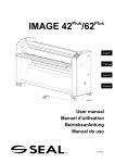
Plus Plus IMAGE 42 /62/62 Roll to Roll User manual UM104RR, Rev. 2.1 September 2002 IMPORTANT The intended use of this device is to be integrated with our existing laminating equipment. This device cannot be used independently. In accordance with the European Machine Directive (89/392/EEC, including 91/368/EEC, 93/44/EEC and 93/68/EEC), a CE-mark has not been affixed on this device; a Manufacturer’s Declaration is provided instead (Article 4.2 and Annex II, sub B). After installation of the Roll-to-Roll device, the CE-mark of the existing laminating equipment is still valid. 1998, 2002, SEAL Graphics, the Netherlands. All rights reserved All information included in this manual as well as information included in supplements or addendum to this manual is subject to copyright law. This information shall not be used, copied, reproduced, transmitted or disclosed to third parties without our prior written consent. SEAL Graphics assumes no responsibility for any errors that may appear in this document nor does it make expressed or implied warranty of any kind with regard to this material, including, but not limited to, the implied warranties of merchantability and fitness for a particular purpose. SEAL Graphics shall not be liable for incidental or consequential damages in connection with, or arising out of the furnishing, performance, or use of this document and the program material which it describes. 2 %106'065 1. GENERAL USE 5 1.1 Unwinder 5 1.2 Winder 5 2. INSTALLATION ON THE IMAGE 42PLUS/62PLUS 6 2.1 Covers 6 2.2 Mounting the unwinder 7 2.3 Mounting the winder 8 3. INSTALLATION ON THE IMAGE 62 9 3.1 Drilling holes 9 3.2 Mounting the winder 10 3 INTRODUCTION 5EQRG This manual refers to the Roll-to-Roll option, available for the following machines: • +OCIG • +OCIG • +OCIG RNWU RNWU This manual contains useful and important information for proper installation and functioning of this equipment. Read this manual carefully before installation and operation. .KCDKNKV[ The data published in this manual are based on the latest information available. They are subject to future modification. We reserve the right to change the construction and/or design of our products, without being obliged to adapt earlier supplies accordingly. )WCTCPVGG The guarantee conditions stated in our terms of delivery, which are in your possession, are applicable to this product. The guarantee on your equipment will become null and void if: service and maintenance are not carried out strictly in accordance with the instructions; repair work is not carried out by our personnel or has been performed without our prior consent in writing; the equipment has been modified without our prior consent in writing; non-original parts are used; the equipment is used inexpertly, incorrectly, carelessly or not in accordance with its nature or intended use. Wearing parts are not covered by the guarantee. 5CHGV[ We have made and will continue to make every effort to inform you as correctly and completely as possible on any dangers associated with the installation and operation of this device. You must ensure and are responsible for compliance with these behavioural guidelines. The buyer/user is obliged to familiarise operating and maintenance personnel with these instructions. Properly check deliveries upon arrival. Always contact your local supplier in the event of damage. 4 1. GENERAL USE 1.1 Unwinder The unwinder may be used for unwinding materials from (cardboard) cores having an inside diameter of 57mm or 76mm (2.3” or 3”). Positioning the material roll: 1. First position the material roll against the left-hand chuck, while depressing the spring, mounted next to this chuck. 2. Place the other side of the material roll on the right-hand chuck, and release the spring. The distance between the chucks can be changed. The supports of the unwinder can be moved along a T-slot at the bottom of the table. Loosen the knobs of the supports by giving them one or two turns. Always move both supports to ensure that the material roll can be positioned in the middle of the machine. Do not forget to retighten the knobs after having moved the supports. When the material roll has been placed between the chucks, then the left-hand chuck’s spring should always be depressed for at least 1 cm (½”). 1.2 Winder The winder may be used for winding materials onto (cardboard) cores having an inside diameter of 76 mm (3”). These cores must be placed on the plastic tube supplied. Positioning an empty core: 1. Always turn off the engine of the machine first by pressing the motor stop button on the control panel. 2. Grab the plastic tube and push it to the right until the tube is released from the left-hand chuck. Pull the tube towards you and out of the machine. 3. Slide an empty cardboard core on the plastic tube. 4. First position the plastic tube including the empty core against the right-hand chuck, tensioning its spring. 5. Position the other end of the plastic tube on the chuck on the left-hand side. Turn the tube until the pin locks into the slot. 6. Position the empty core in the middle of the machine and attach it to the plastic tube using adhesive tape. The switch has the following 3 positions: Automatic: with the switch in this position, the winder will be started and stopped simultaneously with the motor of the laminator. Off: stops and shuts off the winder. Manual operation: use this switch position for rewinding materials without using the laminator. Press and hold the switch in this position when winding. 5 2. INSTALLATION ON THE IMAGE 42PLUS/62PLUS 2.1 Covers The covers must be removed in order to place the Roll-to-Roll winder. A description for removing and replacing the covers is provided below. Right-hand cover (2): 1. Set the mains switch (1) to the "0" (OFF) position and unplug the machine. 2. Note: if the mains switch is not in the "0" position, the right-hand cover cannot be removed. 3. Unscrew all five screws (4). 4. Caution: a yellow-green ground cable (5) is connected to the inside of the cover. Detach this ground cable. 5. Remove the right-hand cover. To replace the right hand cover: perform the actions described above in reverse order. Left-hand cover (3): 1. Set the mains switch to the "0" (OFF) position and unplug the machine. 2. Unscrew all five screws (4). 3. Warning: a yellow-green ground cable (5) is connected to the inside of the cover. Detach this ground cable. 4. Remove the left-hand cover. To replace the left hand cover: perform the actions described above in reverse order. 6 2.2 Mounting the unwinder The unwinder consists of two supports which are to be mounted on the underside of the in-feed table (see front page), into the T-slot containing two hexagonal nuts. Take the left-hand support (1) and position it against the table, with both pins (2), on either side of the nut, into the slot. Take one of the fastening knobs (3) and tighten it, through the support, into the hexagonal nut. Repeat this procedure for the right-hand support (4). The distance between the chucks depends on the length of the core, inside the material roll. Changing this distance is described in the chapter ‘General use’. When the material, being unwound, is running off-track, then the left-hand chuck should be moved slightly in forward or backward direction. To do this: slightly loosen both nuts (5) on either side of the left-hand support, and slide the bolt, holding the chuck, a bit, just as far as necessary. Retighten both nuts again. 7 2.3 Mounting the winder Follow the instructions below: 1. Set the mains switch to the "0" (OFF) position and unplug the machine. 2. Remove both covers from the machine, refer to the chapter “Covers” (2.1) 3. Remove the sealing plug from the opening (8) on the machine rear. Put the provided cable entry plug into the opening. 4. Take the right-hand part of the winder, including the motor (1). Hold it in front of the holes (7) provided in the right-hand frame sheet and insert the bolts (4) through the holes of the winder, into the holes of the frame sheet. On the other side of this sheet, place the star washers on the bolts first and then the nuts. Tighten the nuts. 5. Take the left-hand part of the winder (2). Hold it in front of the holes (9) provided in the left-hand frame sheet and insert the bolts (5) through the slotted holes into the holes of the frame sheet. On the other side of this sheet, place the star washers on the bolts first and then the nuts. Tighten the nuts. 6. Electrical connection: • 4GOQXGVJGEQXGTHTQOVJGYKPFGTWUKPICETQUUJGCFUETGYFTKXGT • &GVCEJVJGYKTGU ,,CPF,YJKEJCTGVKGYTCRRGFVQVJGUKFG QHVJGRNCVGECTT[KPICNNVJGGNGEVTKECNEQORQPGPVU4GOQXGVJGYKTG EQPPGEVQTCPFKPUGTVVJGYKTGUHTQOVJGKPUKFGQWVVJTQWIJVJGECDNG GPVT[RNWI %QPPGEVVJGYKTGUVQVJGRTKPVGFEKTEWKVDQCTFQHVJGYKPFGT QDUGTXKPIVJGEQTTGEVEQFKPI ,,CPF, • 4GHKVVJGEQXGTQHVJGYKPFGT 7. Put the supplied wiring diagram into the transparent pouch on the inside of the right-hand cover. Refit the right-hand cover of the machine, refer to chapter “Covers” (2.1). 7 8 4 9 5 1 6 3 8 2 3. INSTALLATION ON THE IMAGE 62 If you have an Image 42plus or 62plus, you can skip this section. If you have an Image 62, you have to drill a few holes into the machine frame before you can mount the winder. You also have to make a small change in the cable harness to connect the winder electrically. Mount the unwinder as described in chapter 2.2 “Mounting the unwinder”. 3.1 Drilling holes Follow the instructions below: 1. Set the mains switch to the "0" (OFF) position and unplug the machine. 2. Remove both covers from the machine, refer to chapter “Covers”. 3. Place the drilling template at the machine rear against the right-hand frame (4). Let the template rest on the base of the frame, as shown. Use the provided 4mm drill and drill only through holes (1) and (2). Do not drill the holes marked ‘X’. 4. Place the drilling template at the machine rear against the left-hand frame (5). Use the 4mm drill and drill only through holes (3). Do not drill the holes marked ‘X’. 5. Take the provided 8mm drill and drill the four holes (1) and (3) to 8 mm. Take the provided 14.3mm drill and drill the hole (2) to 14.3 mm. 6. Deburr all drilled holes if necessary. : : : 9 3.2 Mounting the winder Place the winder as described in chapter 2.3 “Mounting the winder”. Skip the section on “Electrical connection” and follow the instructions below: 1. Remove the covers (1) from the cable channels. 2. Detach the connector J3 (2) from the printed circuit board. Remove the wires marked J3-1 and J3-2 from this connector (use a small screwdriver). Detach the connector plug (3) from the drive motor and discard these wires. 3. Plug (using the provided wire harness) the connector marked J5 into the motor plug. Connect the wires J3-1, J3-2 and J3-13 to connector J3. Refit the connector on the printed circuit board. 4. Push the new wire harness into the cable channels and make sure that the wires emerge at the bottom right (4) of the plate carrying the electrical components. Refit the covers (1) of the cable channels. 5. Remove the guard from the winder, using a crosshead screwdriver. 6. Now insert the wires from the inside out through the cable entry plug (5) and connect the wire ends J6-1, J6-2 and J6-3 to the printed circuit board of the winder. 7. Refit the guard of the winder. 8. Put the supplied wiring diagram into the transparent pouch on the inside of the right-hand cover. Refit the right-hand cover of the machine, refer to chapter “Covers”. 3 1 2 4 5 10