1
User Manual
EAZ0057B05G Rev.A
Legal Information
Trademarks
Snap-on is a trademark, registered in the United States and other countries, of Snap-on Incorporated. This
publication contains many Snap-on Incorporated trademarks, including but not limited to Snap-on and
ShopStream Connect. All other marks are trademarks or registered trademarks of their respective holders.
Copyright Information
© 2015 Snap-on Incorporated. All rights reserved.
Disclaimer of Warranties and Limitation of Liabilities
All pictures and illustrations shown are for reference purposes only. All information, specifications and illustrations in
this manual are based on the latest information available at the time of printing and are subject to change without
notice. Some functions shown require connection to the Internet.
Snap-on reserves the right to make changes at any time without notice.
Contact Information
Websites:
Snap-on Diagnostics and Information
http://diagnostics.snapon.co.uk
http://www1.snapon.com/diagnostics/UK/Diagnostics/ShopStreamConnect.htm
Customer Care and Technical Assistance - Phone / E- mail
+44 (0) 845 601 4736 / [email protected]
For technical assistance in all other markets, contact your selling agent
EAZ0057B05G Rev.A 8-G-15 GB
ii
Safety Information
For your own safety, the safety of others, and to prevent damage to the product and vehicles upon
which it is used, it is important that all instructions and safety messages in this manual and the
accompanying Important Safety Instructions manual be read and understood by all persons
operating, or coming into contact with the product, before operating. We suggest you store a copy
of each manual near the product in sight of the operator.
For your safety, read all instructions. Use your Diagnostic Tools only as described in the
Diagnostics Tool user’s manual. Use only manufacturer recommended parts and accessories with
your Diagnostic Tools.
This product is intended for use by properly trained and skilled professional automotive
technicians. The safety messages presented throughout this manual and the accompanying
Important Safety Instructions manual are reminders to the operator to exercise extreme care when
using this product.
There are many variations in procedures, techniques, tools, and parts for servicing vehicles, as
well as in the skill of the individual doing the work. Because of the vast number of test applications
and variations in the products that can be tested with this instrument, we cannot possibly
anticipate or provide advice or safety messages to cover every situation. It is the responsibility of
the automotive technician to be knowledgeable of the system being tested. It is essential to use
proper service methods and test procedures. It is important to perform tests in an appropriate and
acceptable manner that does not endanger your safety, the safety of others in the work area, the
equipment being used, or the vehicle being tested.
It is assumed that the operator has a thorough understanding of vehicle systems before using this
product. Understanding of these system principles and operating theories is necessary for
competent, safe and accurate use of this instrument.
Before using the equipment, always refer to and follow the safety messages and applicable test
procedures provided by the manufacturer of the vehicle or equipment being tested. Use the
product only as described in it’s user manual. Use only manufacturer recommended parts and
accessories with your product.
Read, understand and follow all safety messages and instructions in this manual, the
accompanying Important Safety Instructions manual, and on the test equipment.
Environmental Conditions:
• This product is intended for indoor use only
• This product is rated for Pollution Degree 2 (normal conditions)
v
Safety Information
Safety Signal Words
Safety Signal Words
All safety messages contain a safety signal word that indicates the level of the hazard. An icon,
when present, gives a graphical description of the hazard. Safety Signal words are:
'$1*(5
Indicates an imminently hazardous situation which, if not avoided, will result in death or serious
injury to the operator or to bystanders.
:$51 ,1*
Indicates a potentially hazardous situation which, if not avoided, could result in death or serious
injury to the operator or to bystanders.
&$87,21
Indicates a potentially hazardous situation which, if not avoided, may result in moderate or minor
injury to the operator or to bystanders.
Safety Message Conventions
Safety messages are provided to help prevent personal injury and equipment damage. Safety
messages communicate the hazard, hazard avoidance and possible consequences using three
different type styles:
• Normal type states the hazard.
• Bold type states how to avoid the hazard.
• Italic type states the possible consequences of not avoiding the hazard.
An icon, when present, gives a graphical description of the potential hazard.
Safety Message Example
:$51 ,1*
Risk of unexpected vehicle movement.
• Block drive wheels before performing a test with engine running.
A moving vehicle can cause injury.
Important Safety Instructions
For a complete list of safety messages, refer to the accompanying Important Safety Instructions
manual provided with your Diagnostic Tool or on our website. See the website contact information
on page ii for website addresses.
SAVE THESE INSTRUCTIONS
vi
Contents
Safety Information ................................................................................................................ v
Chapter 1: Using This Manual ............................................................................................. 3
Content ................................................................................................................................... 3
Conventions............................................................................................................................ 3
Terminology ..................................................................................................................... 3
Symbols ........................................................................................................................... 3
Bold Text .......................................................................................................................... 4
Notes and Important Messages ....................................................................................... 4
Hyperlinks ........................................................................................................................ 4
Procedures....................................................................................................................... 4
Chapter 2: Introduction........................................................................................................ 5
Chapter 3: Downloading and Installing ShopStream Connect ........................................ 6
Verifying Minimum PC Requirements..................................................................................... 6
Verifying PC System Properties....................................................................................... 7
Download and Installation ......................................................................................................8
Chapter 4: Getting Started................................................................................................. 10
Starting the Software ............................................................................................................ 10
Connecting a Diagnostic Tool to a PC.................................................................................. 11
Establishing Communication ................................................................................................ 14
ETHOS........................................................................................................................... 14
ETHOS+.........................................................................................................................15
MICROSCAN ................................................................................................................. 17
MICROSCAN III ............................................................................................................. 17
MODIS ........................................................................................................................... 18
MODIS Ultra................................................................................................................... 19
SOLUS ........................................................................................................................... 20
SOLUS PRO .................................................................................................................. 21
SOLUS Ultra .................................................................................................................. 22
Vantage PRO ................................................................................................................. 23
Vantage Ultra ................................................................................................................. 24
Terminating Communication................................................................................................. 25
Exiting the Software.............................................................................................................. 26
Chapter 5: Basic Navigation and Operation .................................................................... 27
Main Screen Layout.............................................................................................................. 27
Main Menu Bar ..................................................................................................................... 28
File Menu ....................................................................................................................... 28
Edit Menu ....................................................................................................................... 28
Tools Menu .................................................................................................................... 29
Help Menu......................................................................................................................31
Data Manager Screen Controls and Icons ........................................................................... 32
Display Tabs .................................................................................................................. 32
Keyboard and Mouse Controls ...................................................................................... 34
1
Contents
Data Manager Toolbar Icons ......................................................................................... 35
Chapter 6: Transferring Files ............................................................................................ 39
File Transfer Basics.............................................................................................................. 39
Folder and Files ............................................................................................................. 39
Displaying Files .............................................................................................................. 40
Copying Files ................................................................................................................. 41
Moving Files ...................................................................................................................41
Alternate Method............................................................................................................ 41
Chapter 7: Viewing Files .................................................................................................... 42
Scanner DataViewer.............................................................................................................43
Menu Bar .......................................................................................................................44
Display Toolbar .............................................................................................................. 48
Navigation Tools ............................................................................................................ 49
Customizing the Display................................................................................................. 51
Customizing the Parameter List ..................................................................................... 52
Scope Viewer ....................................................................................................................... 54
Toolbar ........................................................................................................................... 55
Main Body ......................................................................................................................58
Profile Controls Window................................................................................................. 58
Playback Control Toolbar............................................................................................... 59
Image Viewer........................................................................................................................ 60
Scanner Code Viewer...........................................................................................................61
Chapter 8: Updating and Upgrading Software.................................................................63
ShopStream Connect Software Update ......................................................................... 64
Diagnostic Tool Software Service Release Update ....................................................... 65
Diagnostic Tool Software Subscription Upgrade............................................................ 65
Appendix A: Communicating with Early MODIS Diagnostic Tools ............................... 68
Viewing Early MODIS Files .................................................................................................. 68
Service Releases and early MODIS Diagnostic Tools ......................................................... 69
Index .................................................................................................................................... 70
2
Chapter 1
Using This Manual
1.1 Content
This manual contains basic operating instructions and is structured in a manner to help you
become familiar with and perform basic operations.
The illustrations in this manual are intended as reference only and may not depict actual screen
results, information, functions or standard equipment.
1.2 Conventions
The following conventions are used.
1.2.1 Terminology
The terms “Scanner” and “Scanner function” are used to describe the Scanner Function(s) of the
Diagnostic Tool.
Examples:
• Select Scanner from the Home screen.
• From the Scanner main menu select Continue.
• The Scanner function provides many diagnostic tests.
The term “select” describes tapping/touching an icon on the touch screen, or highlighting an icon
or menu choice and then selecting the confirmation menu choice such as Continue, Accept, OK,
Yes, or other similar choice.
Abbreviated example for the following procedure: “Select Brightness”
1. Navigate to and highlight the Brightness selection.
2. Select OK, or similar, button.
1.2.2 Symbols
Different types of arrows are used. The “greater than” arrow (>) indicates an abbreviated set of
selection (navigation) instructions.
Abbreviated example for the following procedure: “Select Tools > Connect-to-PC”
1. Select Tools from the home screen.
2. Highlight Connect-to-PC on the Tools menu.
3. Select Connect-to-PC.
The solid arrows (e, c, d, b) are navigational instructions for the four directions of the directional
buttons.
Example: Press the down d arrow.
3
Using This Manual
Conventions
1.2.3 Bold Text
Bold emphasis is used in procedures to highlight selectable items such as control buttons, icons
and menu options.
Example: Press the OK button
1.2.4 Notes and Important Messages
The following messages are used.
Notes
A NOTE provides helpful information such as additional explanations, tips, and comments.
Example:
i
NOTE:
For additional information refer to...
Important
IMPORTANT indicates a situation which, if not avoided, may result in damage to the test
equipment or vehicle.
Example:
IMPORTANT:
Do not disconnect the data cable while the Diagnostic Tool is communicating with the ECM.
1.2.5 Hyperlinks
Hyperlinks, or hot links, that take you to other related articles, procedures, and illustrations are
available in electronic documents. Blue colored text indicates a selectable hyperlink.
Example:
IMPORTANT:
Read all applicable Safety Information before using this Diagnostic Tool!
1.2.6 Procedures
An arrow icon in the left-margin area indicates a procedure.
Example:
z
To change screen views:
1. Select the Graph icon.
The dropdown menu displays.
2. Select an option from the menu.
The screen layout changes to the format selected.
4
Chapter 2
Introduction
The ShopStream Connect™ software is PC-based software that extends the capabilities of your
Diagnostic Tools. Using ShopStream Connect software with your Diagnostic Tools allows you to
do the following:
•
Exchange data files bi-directionally between the Diagnostic Tool and the PC.
•
View Diagnostic Tool data files on a PC screen.
•
Add or edit notes and comments to Diagnostic Tool data files.
•
Install software updates from a PC onto the Diagnostic Tool.
ShopStream Connect can be used with the following Diagnostic Tools:
•
ETHOS®
•
ETHOS®+
•
MICROSCAN®
•
MICROSCAN® III
•
MODIS
•
MODIS Ultra
•
SOLUS™
•
SOLUS™ PRO
•
SOLUS Ultra®
•
Vantage PRO™
•
VANTAGE® Ultra
5
Chapter 3
Downloading and Installing
ShopStream Connect
ShopStream Connect software should only be installed on a personal computer (PC) meeting the
minimum requirements listed below.
3.1 Verifying Minimum PC Requirements
IMPORTANT:
If your PC does not meet the minimum requirements, do not attempt to install the ShopStream
Connect software.
Before installing the software, verify your PC meets the following requirements:
•
System Properties:
– Operating system—Windows® XP, 7, 8 or 8.1 (Windows XP must be updated to
Microsoft .NET Framework Version 4.0)
– Processor—Intel® Pentium 4 or later, or equivalent
– Memory—256 MB minimum, 512 MB recommended
•
Hard Drive—500 MB free space
•
CD-ROM, DVD, or DVD-ROM drive (optional)
•
USB 2.0 or later
•
Internet Explorer 6.0 or higher
•
Internet connection
•
Adobe® Reader software (free download at www.adobe.com/products/reader)
A USB cable is also needed to connect the Diagnostic Tool to the PC. The type of USB cable
needed varies by the type of Diagnostic Tool:
– ETHOS, ETHOS+, MICROSCAN III, MODIS, MODIS Ultra, SOLUS PRO, SOLUS Ultra,
and Vantage PRO and Vantage Ultra use a type mini A USB cable.
– SOLUS and MICROSCAN use a type A/B USB cable.
IMPORTANT:
Older MODIS Diagnostic Tools do not have a type mini A USB port, and therefore cannot be
directly updated using ShopStream Connect. The USB port is located under the left handgrip on
the circuit board near the side CF card slot. If there is no USB port, the program CF card (in the
side slot) can be updated through ShopStream Connect using a CF card reader/writer.
A CompactFlash® (CF) card reader is also needed for updating SOLUS, Vantage PRO, and early
MODIS Diagnostic Tools.
6
Downloading and Installing ShopStream Connect
Verifying Minimum PC Requirements
3.1.1 Verifying PC System Properties
Follow the procedures below to check your PC system properties and to determine how much free
space is available on your hard drive.
z
To check your PC system properties:
1. On the Desktop, right-click My Computer to open the menu.
2. Select Properties from the menu.
The System Properties dialog box displays with your system information (Figure 3-1).
1— System property information
2— Hard drive information
Figure 3-1 Typical Windows XP System Properties dialog box
z
To check PC hard drive free space:
1. On the Desktop, double-click My Computer.
2. Select View > Details (Figure 3-2).
Figure 3-2 Typical PC hard drive free space details
7
Downloading and Installing ShopStream Connect
Download and Installation
3.2 Download and Installation
Follow the procedure below to download the ShopStream Connect software.
z
To download the software:
1. From your PC, using your Internet browser, go to the ShopStream Connect website. See
website information on page “ii” of this manual.
2. Locate the ShopStream Connect software download.
3. Follow the on-screen instructions.
After downloading, install the ShopStream Connect software onto your PC as follows.
z
To install the ShopStream Connect software:
1. Locate the ShopStream Connect software installer that downloaded onto your PC, and then
double-click ShopStreamConnect.exe
The Setup Wizard launches and a welcome screen displays.
2. Select Next to begin the installation (Figure 3-3).
Figure 3-3 Typical Welcome screen
A Select Market screen opens.
3. Choose your geographical market location.
A Software License Agreement screen opens.
4. From the License Agreement screen:
a. Scroll to read through the entire Snap-on Incorporated Software License Agreement.
b. Select the I accept the terms of the license agreement check box.
c. Select Next to continue (Figure 3-4).
Figure 3-4 Typical License Agreement screen
8
Downloading and Installing ShopStream Connect
Download and Installation
A Ready to Install screen displays.
5. Select Install to begin installation (Figure 3-5).
Then the Setup Status screen tracks the progress as the program installs.
Figure 3-5 Typical install and status screens
6. Select Finish to close the Install Wizard when prompted (Figure 3-6).
Figure 3-6 Typical Complete screen
A shortcut icon is added to the desktop (Figure 3-7).
Figure 3-7 ShopStream Connect icon
7. Double-click the desktop shortcut icon to start ShopStream Connect.
9
Chapter 4
Getting Started
This section explains how to connect your Diagnostic Tool to your personal computer (PC), and
how to establish communication with the ShopStream Connect™ software.
IMPORTANT:
First, the ShopStream Connect software must be installed on your PC. See, "Downloading and
Installing ShopStream Connect" on page 6 for additional information.
4.1 Starting the Software
The ShopStream Connect software runs on your PC. Starting the software can vary depending on
the Windows operating system installed on your PC and your setup preferences. Typically the
software can be started from:
z
•
The Windows Start menu
•
The ShopStream Connect shortcut icon on the Windows desktop (automatically created
during installation)
To start from the Windows desktop:
•
z
Double-click ShopStream Connect shortcut icon.
To start from the Windows Start menu:
•
Select Start > Programs > ShopStream Connect > ShopStream Connect (Figure 4-1 and
Figure 4-2).
Figure 4-1 Start menu selection (Typical - Windows XP Professional shown)
Figure 4-2 Start menu selection (Typical - Windows 7 shown)
10
Getting Started
Connecting a Diagnostic Tool to a PC
4.2 Connecting a Diagnostic Tool to a PC
Two types of USB cable (Mini A type and A/B type) are used to connect Diagnostic Tools to your
PC. There are three types of USB cable connector (Figure 4-3):
1— Type A connector—used on your PC
2— Type mini A connector—used on ETHOS, ETHOS+, MICROSCAN III, MODIS,
MODIS Ultra, SOLUS PRO, SOLUS Ultra, Vantage PRO and Vantage Ultra
3— Type B connector—used on MICROSCAN and SOLUS
Figure 4-3 USB connector types
z
To connect a Diagnostic Tool to a PC:
1. Plug the Type A end of a USB cable into a Type A USB port on your PC.
2. Plug the other end of the USB cable into the appropriate USB port on the Diagnostic Tool:
– ETHOS—mini A USB port on top of the Diagnostic Tool (Figure 4-4).
Figure 4-4
– ETHOS+ —mini A USB port on top of the Diagnostic Tool (Figure 4-5).
Figure 4-5
– MICROSCAN—type B USB port on top of the Diagnostic Tool (Figure 4-6).
Figure 4-6
11
Getting Started
Connecting a Diagnostic Tool to a PC
– MICROSCAN III—type mini A USB port on top of the Diagnostic Tool (Figure 4-7).
Figure 4-7
– MODIS—mini A USB port mounted on the circuit board, above the compact flash card
under the left handgrip of the Diagnostic Tool (Figure 4-8).
Figure 4-8
IMPORTANT:
Older MODIS Diagnostic Tools do not have a USB port on the circuit board by the side CF card
slot, and they cannot be connected to a PC with a cable. However, saved files can be viewed with
ShopStream Connect and older Diagnostic Tools can be upgraded to current specifications. Refer
to "Communicating with Early MODIS Diagnostic Tools" on page 68 for additional information.
– MODIS Ultra—mini A USB port on top of the Diagnostic Tool (Figure 4-9).
6'
*1'
9
Figure 4-9
– SOLUS—type B USB port on top of the Diagnostic Tool (Figure 4-10).
Figure 4-10
12
Getting Started
Connecting a Diagnostic Tool to a PC
– SOLUS PRO—mini A USB port on top of the Diagnostic Tool (Figure 4-11).
Figure 4-11
– SOLUS Ultra—mini A USB port on top of the Diagnostic Tool (Figure 4-12).
Figure 4-12
– Vantage PRO—mini A USB port under the sliding panel on top of the Diagnostic Tool.
(Figure 4-13).
Figure 4-13
– Vantage Ultra—mini A USB port on top of the Diagnostic Tool. (Figure 4-14).
6'
*1'
9
Figure 4-14
13
Getting Started
Establishing Communication
4.3 Establishing Communication
Establishing communication varies slightly for each Diagnostic Tool. Use one of the following
procedures to establish communication between your Diagnostic Tool and your PC:
•
ETHOS refer to page 14
•
ETHOS+ refer to page 15
•
MICROSCAN refer to page 17
•
MICROSCAN III refer to page 17
•
MODIS refer to page 18
•
MODIS Ultra refer to page 19
•
SOLUS refer to page 20
•
SOLUS PRO refer to page 21
•
SOLUS Ultra refer to page 22
•
Vantage PRO refer to page 23
•
Vantage Ultra refer to page 24
4.3.1 ETHOS
z
To establish communication with your ETHOS Diagnostic Tool:
1. Power off the ETHOS Diagnostic Tool.
2. On the PC, start the ShopStream Connect software (see "Starting the Software" on page 10).
3. On the ETHOS Diagnostic Tool, simultaneously hold down the Y/a and N/x buttons, and then
press the Power button.
The Service Menu displays (Figure 4-15).
Figure 4-15 Service menu
4. On the ETHOS Diagnostic Tool, from the Service Menu, select PC-LINK.
5. Connect the USB cable to both the ETHOS Diagnostic Tool and the PC.
14
Getting Started
Establishing Communication
IMPORTANT:
Unless you are specifically instructed to do so and have precise instructions, do not attempt to use
any other functions on the Service Menu. Improper use of Service Menu functions can corrupt the
internal file structure and render the Diagnostic Tool inoperative.
6. If a “removable disk” dialog automatically opens on your PC, select Cancel.
7. ShopStream Connect should default to display the data stored on your ETHOS Diagnostic
Tool. If not, select ETHOS from the end of the file directory list.
Once communication is established between your PC and ETHOS, the Mounting screen
displays on your ETHOS Diagnostic Tool (Figure 4-16).
Figure 4-16 Mounting screen
4.3.2 ETHOS+
z
To establish communication with your ETHOS+ Diagnostic Tool:
1. Press the Power button to turn on the ETHOS+ Diagnostic Tool.
2. Connect the USB cable between the ETHOS+ and your PC:
a. The type A connector cable end attaches to a USB port on the PC.
b. The type mini A connector cable end attaches to the USB port on top of the ETHOS+.
3. From the Home screen, select Tools > Connect-to-PC.
The screen message shows the Diagnostic Tool is ready to connect to a PC (Figure 4-17).
15
Getting Started
Establishing Communication
Figure 4-17 Ready to connect screen (ETHOS+)
4. Select Continue once the USB cable has been connected.
The screen message now changes to show the ETHOS+ and PC are connected (Figure 4-18)
5. Launch ShopStream Connect (see "Starting the Software" on page 10).
ShopStream Connect should default to display the data stored on your ETHOS+ Diagnostic
Tool. If not, select ETHOS+ from the end of the file directory list.
Figure 4-18 In Connect-to-PC mode message (ETHOS+)
16
Getting Started
Establishing Communication
4.3.3 MICROSCAN
z
To establish communication with your MICROSCAN Diagnostic Tool:
1. Connect the A end of the Type A/B USB cable to a USB port on the PC.
2. Connect the B end of the USB cable to the port on top of the MICROSCAN Diagnostic Tool.
The MICROSCAN automatically powers up and displays the service menu.
3. Highlight Connect to PC on the MICROSCAN service menu (Figure 4-19).
&RQQHFW7R3&06'0RGH
6RIWZDUH8SGDWH
61)())))
))%
Figure 4-19 Connect to PC screen
4. Press Y on the MICROSCAN to make the selection.
The MICROSCAN screen changes to indicate it is now connected to the PC.
5. Double click ShopStream Connect from the desktop on your PC to launch the program.
6. ShopStream Connect should default to display the data stored on your MICROSCAN
Diagnostic Tool. If not, select MICROSCAN from the end of the file directory list.
4.3.4 MICROSCAN III
z
To establish communication with your MICROSCAN III Diagnostic Tool:
1. Connect the A end of the USB cable to a USB port on the PC.
2. Connect the mini A end of the USB cable to the port on top of the MICROSCAN III Diagnostic
Tool.
The MICROSCAN III automatically powers up to the USB Power Menu (Figure 4-20).
Figure 4-20 Connect to PC screen
3. Select Connect to PC on the MICROSCAN III touch screen.
17
Getting Started
Establishing Communication
The MICROSCAN III screen changes to indicate it is now connected to the PC.
4. Double click ShopStream Connect from the desktop of your PC to launch the program.
5. ShopStream Connect should default to display the data stored on your MICROSCAN III
Diagnostic Tool. If not, select MICROSCAN III from the end of the file directory list.
4.3.5 MODIS
z
To establish communication with your MODIS Diagnostic Tool:
IMPORTANT:
Older MODIS Diagnostic Tools do not have a USB port on the circuit board by the side CF card
slot, and they cannot be connected to a PC with a cable. However, saved files can be viewed with
ShopStream Connect and older Diagnostic Tools can be upgraded to current specifications. Refer
to "Communicating with Early MODIS Diagnostic Tools" on page 68 for additional information.
1. Press the Power button to turn on the MODIS Diagnostic Tool.
2. From the Main Menu, Select UTILITIES > Connect to PC, and press Y.
3. Press Y to turn off the Diagnostic Tool when the configure for Connect to PC message
displays.
4. Press the Power button to turn on the MODIS Diagnostic Tool.
A Connect to PC mode message displays (Figure 4-21)
Figure 4-21 MODIS in Connect to PC mode message
5. Connect the USB cable between the MODIS and your PC:
a. The type A connector cable end attaches to a USB port on the PC.
b. The type mini A cable connector attaches to the mini USB port, which is mounted on the
circuit board, above the CF card under the left handgrip of the MODIS Diagnostic Tool.
IMPORTANT:
A USB mini A strain relief clip (EAS2036L38A) must be installed (Figure 4-22). The clip is a thin
metal shield that surrounds the connector and secures it to the circuit board. Contact your selling
agent if you need the clip.
18
Getting Started
Establishing Communication
1— MODIS mini A USB port without a strain relief clip
2— Strain relief clip installed on a MODIS mini A USB port
Figure 4-22 Strain Relief Clip EAS2036L38A
6. If a “removable disk” dialog automatically opens on your PC, select Cancel.
7. Launch ShopStream Connect (see "Starting the Software" on page 10).
ShopStream Connect should default to display the data stored on your MODIS Diagnostic
Tool. If not, select MODIS from the end of the file directory list.
4.3.6 MODIS Ultra
z
To establish communication with your MODIS Ultra Diagnostic Tool:
1. Press the Power button to turn on the MODIS Ultra Diagnostic Tool.
2. Connect the USB cable between the MODIS Ultra and your PC:
a. The type A connector cable end attaches to a USB port on the PC.
b. The type mini A connector cable end attaches to the USB port on top of the MODIS Ultra.
3. From the Home screen, select Tools > Connect-to-PC.
The screen message shows the Diagnostic Tool is ready to connect to a PC (Figure 4-23).
Figure 4-23 Modis Ultra ready to connect screen
19
Getting Started
Establishing Communication
4. Select Continue once the USB cable has been connected.
A screen message shows the MODIS Ultra and PC are connected (Figure 4-24).
5IJTEFWJDFJTOPXJO$POOFDUUP1$NPEF
1SFTT 9 UP FYJU
Figure 4-24 Modis Ultra in Connect-to-PC mode message
5. Launch ShopStream Connect (see "Starting the Software" on page 10).
ShopStream Connect should default to display the data stored on your MODIS Ultra
Diagnostic Tool. If not, select MODIS Ultra from the end of the file directory list.
4.3.7 SOLUS
z
To establish communication with your SOLUS Diagnostic Tool:
1. Press the Power button to turn on the SOLUS Diagnostic Tool.
2. From the Main Menu, navigate to UTILITIES > Connect to PC (Figure 4-25).
Figure 4-25 SOLUS utilities menu
3. Press Y, then a configuring for Connect to PC message displays.
4. Press Y to turn off the SOLUS Diagnostic Tool.
5. Press the Power button to turn on the SOLUS Diagnostic Tool and a message displays
(Figure 4-26).
20
Getting Started
Establishing Communication
Figure 4-26 SOLUS in Connect to PC mode message
6. Connect the USB cable between the SOLUS and your PC:
a. The type A connector cable end attaches to a USB port on the PC.
b. The type B connector cable end attaches to the USB port on top of the SOLUS
Diagnostic Tool.
7. If a “removable disk” dialog automatically opens on your PC, select Cancel.
8. Launch ShopStream Connect (see "Starting the Software" on page 10).
ShopStream Connect should default to display the data stored on your SOLUS Diagnostic
Tool. If not, select SOLUS from the end of the file directory list.
4.3.8 SOLUS PRO
z
To establish communication with your SOLUS PRO Diagnostic Tool:
1. Press the Power button to turn on the SOLUS PRO Diagnostic Tool.
2. From the Main Menu, navigate to UTILITIES > Connect to PC (Figure 4-27).
Figure 4-27 SOLUS PRO utilities menu
3. Press Y to select and a configuring for Connect to PC message displays.
4. Press Y to turn off the SOLUS PRO Diagnostic Tool.
5. Press the Power button to turn on the SOLUS PRO Diagnostic Tool.
A Connect to PC mode message displays (Figure 4-28).
21
Getting Started
Establishing Communication
Figure 4-28 SOLUS PRO in Connect to PC mode message
6. Connect the USB cable between the SOLUS PRO and your PC:
a. The type A connector cable end attaches to a USB port on the PC.
b. The type mini A connector cable end attaches to the USB port on top of the SOLUS PRO.
7. If a “removable disk” dialog automatically opens on your PC, select Cancel.
8. Launch ShopStream Connect (see "Starting the Software" on page 10).
ShopStream Connect should default to display the data stored on your SOLUS PRO
Diagnostic Tool. If not, select SOLUS PRO from the end of the file directory list.
4.3.9 SOLUS Ultra
z
To establish communication with your SOLUS Ultra Diagnostic Tool:
1. Press the Power button to turn on the SOLUS Ultra Diagnostic Tool.
2. Connect the USB cable between the SOLUS Ultra and your PC:
a. The type A connector cable end attaches to a USB port on the PC.
b. The type mini A connector cable end attaches to the USB port on top of the SOLUS Ultra.
3. From the Home screen, select Tools > Connect-to-PC.
The screen message shows the Diagnostic Tool is ready to connect to a PC (Figure 4-29).
Figure 4-29 SOLUS Ultra ready to connect screen
4. Select Continue once the USB cable has been connected.
A screen message shows the SOLUS Ultra and PC are connected (Figure 4-30).
22
Getting Started
Establishing Communication
Figure 4-30 SOLUS Ultra in Connect-to-PC mode message
5. Launch ShopStream Connect (see "Starting the Software" on page 10).
ShopStream Connect should default to display the data stored on your SOLUS Ultra
Diagnostic Tool. If not, select SOLUS Ultra from the end of the file directory list.
4.3.10 Vantage PRO
z
To establish communication with your Vantage PRO Diagnostic Tool:
1. Press the Power button to turn on the Vantage PRO Diagnostic Tool.
2. From the Main Menu, navigate to UTILITIES > Connect to PC (Figure 4-31).
Figure 4-31 Vantage PRO utilities menu
3. Press Y, then a configuring for Connect to PC message displays.
4. Press Y to turn off the Vantage PRO Diagnostic Tool.
5. Press the Power button to turn on the Vantage PRO Diagnostic Tool and a Connect to PC
mode message displays (Figure 4-32).
23
Getting Started
Establishing Communication
Figure 4-32 Vantage PRO in Connect to PC mode message
6. Connect the type A connector of the USB cable to a USB port on the PC, and between the
mini A connector end of the cable to the Vantage PRO Diagnostic Tool.
7. If a “removable disk” dialog automatically opens on your PC, select Cancel.
8. Launch ShopStream Connect (see "Starting the Software" on page 10).
ShopStream Connect should default to display the data stored on your Vantage PRO. If not,
select Vantage PRO from the end of the file directory list.
4.3.11 Vantage Ultra
z
To establish communication with your Vantage Ultra Diagnostic Tool:
1. Press the Power button to turn on the Vantage Ultra Diagnostic Tool.
2. Connect the USB cable between the Vantage Ultra and your PC:
a. The type A connector cable end attaches to a USB port on the PC.
b. The type mini A connector cable end attaches to the USB port on top of the
Vantage Ultra.
3. From the Home screen, select Tools > Connect-to-PC.
The screen message shows the Diagnostic Tool is ready to connect to a PC (Figure 4-33).
24
Getting Started
Establishing Communication
Figure 4-33 Vantage Ultra ready to connect screen
4. Select Continue once the USB cable has been connected.
A screen message shows the Vantage Ultra and PC are connected (Figure 4-34)
5IJTEFWJDFJTOPXJO$POOFDUUP1$NPEF
1SFTT 9 UP FYJU
Figure 4-34 Vantage Ultra in Connect-to-PC mode message
5. Launch ShopStream Connect (see "Starting the Software" on page 10).
ShopStream Connect should default to display the data stored on your Vantage Ultra
Diagnostic Tool. If not, select Vantage Ultra from the end of the file directory list.
25
Getting Started
Terminating Communication
4.4 Terminating Communication
z
To terminate communication between your Diagnostic Tool and PC:
1. From the Diagnostic Tool, select Exit from the Connect-to-PC mode screen to terminate
communication (Figure 4-35).
5IJTEFWJDFJTOPXJO$POOFDUUP1$NPEF
1SFTT 9 UP FYJU
Figure 4-35 Typical - Exit selection
2. Disconnect the USB cable from the Diagnostic Tool.
4.5 Exiting the Software
z
To exit the ShopStream Connect software:
1. Select Exit from the dropdown menu (Figure 4-36).
Figure 4-36 Exit selection
2. Disconnect the USB cable from your PC.
26
Basic Navigation and
Operation
Chapter 5
5.1 Main Screen Layout
The following explains the screen layout for ShopStream Connect™ software.
1— Notes Window—allows you add notes to select data files. Select Save from the menu
bar to save your notes. NOTE: Not all file types allow notes, the Notes window will be
grayed out when a file type that does not support notes is highlighted. Some image files
may display notes for reference purposes (the notes are grayed out and not editable).
2— File directory structure—displays the file directory structure of your PC in standard
Windows format, and shows any connected Diagnostic Tools at the bottom of the data list.
3— Data Manager Toolbar—provides control icons that perform a variety of operations on
data files.
4— Main Menu bar—contains File, Edit, Tools, and Help menus.
5— Tabs—provides access to data files and presets stored on the Diagnostic Tool or on the
PC, and also allows viewing of software revision details of the Diagnostic Tool.
6— Main display—shows stored data files details. NOTE: The files listed are sortable
(ascending/descending) by clicking on the column tab at the top (e.g. File Name, Type,
etc.) Sort preferences are saved when the ShopStream Connect program is closed.
7— Preview—displays a sample of the file if the selected file is a image file.
Figure 5-1 ShopStream Connect screen layout
27
Basic Navigation and Operation
Main Menu Bar
5.2 Main Menu Bar
The Main Menu Bar includes the following menu options:
•
File
•
Edit
•
Tools
•
Help
Figure 5-2 Main menu bar
5.2.1 File Menu
The following functions are available from the File menu:
•
Exit—Closes the ShopStream Connect software.
•
Open File—This function is used to open data files for viewing. The ShopStream Connect
software lets you view data files stored on both the computer and the Diagnostic Tool. This
operation is also available with a right-click of the mouse.
•
Copy to...—This function creates a duplicate of the selected files at the other location (PC if
the file is on the Diagnostic Tool or Diagnostic Tool if the file is on the PC). This operation is
also available with a right-click of the mouse.
•
Move to...—This function moves selected files to another location (to the PC from the
Diagnostic Tool, or to the Diagnostic Tool from the PC). This operation is also available with a
right-click of the mouse.
•
Delete—This function erases the selected files. This operation is also available with a rightclick of the mouse.
•
Edit—This function changes the name of file selection. This operation is also available with a
right-click of the mouse.
•
Email—This function starts an E-mail message with a copy of file selections attached. This
operation is also available with a right-click of the mouse.
•
Refresh File List—Resamples and cleans up the display screen.
•
Print—Sends the current screen to a printer.
5.2.2 Edit Menu
The Edit menu functions, follow Windows operational standards.
The following functions are available from the Edit menu:
•
Cut File(s)—Removes the selected text or file and places it on the clipboard.
•
Copy File(s)—Copies the selected text or file on the clipboard.
•
Paste File(s)—Inserts the contents of the clipboard at the current location.
28
Basic Navigation and Operation
Main Menu Bar
5.2.3 Tools Menu
The Tools menu includes the following options:
•
Update Software
•
Options
Update Software
This function allows you to download updates and upgrades for your Diagnostic Tools and
ShopStream Connect software. See “Updating and Upgrading Software” on page 63.
Options
This function allows you to enter shop information to be added to printed files and to change the
location of the saved data files on the PC. Selecting Options opens a submenu that offers the
following:
•
Autostart—automatically launches ShopStream Connect whenever a Diagnostic Tool in
Connect-to-PC mode is connected to the computer.
•
Edit Shop Info—allows you to add your shop name and information to printed files.
•
Change ShopStream Data Folder Path—allows you to select a different target destination
for the Diagnostic Tools folder on your PC.
Autostart
ShopStream Connect automatically launches if a Diagnostic Tool is in Connect-to-PC mode, or
the CF card from a MODIS, SOLUS, or Vantage PRO, is recognized by your PC when Autostart
is active. This feature can be switched off and on by selecting it from the options submenu. A
check mark alongside the name indicates Autostart is active.
29
Basic Navigation and Operation
Main Menu Bar
Edit Shop Info
Selecting Edit Shop Info opens a dialog box that allows you to enter the name address, and
phone number for your shop, which can be included as a header on printed files. The date and
time are automatically placed on the top line, and messages of up to three lines can also be added
below the shop information. A preview panel at the bottom of the box shows how the information
will appear on a print out (Figure 5-3).
Figure 5-3 Edit Shop Info dialog box
Check the “Use Shop Info in Printout Header” box to automatically include the header on printed
files. Select Edit Shop Info from the Options submenu to modify or add messages before printing.
30
Basic Navigation and Operation
Main Menu Bar
Change ShopStream Data Folder Path
When a diagnostic tool is connected to your PC using ShopStream Connect, a Diagnostic Tool
folder is created on your PC named after the connected platform (e.g. ETHOS+, SOLUS, MODIS
Ultra, etc). This folder allows you to store and transfer files.
The Change ShopStream Data Folder Path option allows you to select a different target
destination for saving Scanner files to on your PC. Selecting opens a dialog box that allows you to
browse the menu structure on your computer (Figure 5-4). Follow the onscreen instructions to
create or rename your new “target destination” folder and/or location.
Figure 5-4
Highlight the desired destination folder for your saved files, then select OK. Selecting Make New
Folder adds a new destination folder within the currently highlighted folder.
5.2.4 Help Menu
The Help menu includes useful information and links to help you get acquainted with and learn
how to use ShopStream Connect.
Figure 5-5 Help menu
About ShopStream Connect - Displays ShopStream Connect software version information.
31
Basic Navigation and Operation
Data Manager Screen Controls and Icons
Whats New - Opens a submenu of links to learn about new platform information, accessories and
the Subscription Manager Feature.
•
ShopStream Connect Subscription Manager Feature (User Manual Link).
•
What's New in Platform Coverage (Webpage Link).
•
Optional Platform Accessories (Webpage Link).
ShopStream Connect Basics - opens quick links to the following topics in the User Manual.
•
How to transfer files from Diagnostic Tool to PC.
•
How to view files.
•
How to download and install a software service release using Update Manager.
•
How to download and install a software upgrade using Subscription Manager.
Manuals and Instructions - opens quick links to the User Manual and Installation Instructions.
•
ShopStream Connect Installation Instructions (User Manual Link).
•
ShopStream Connect User Manual.
Support - opens quick links found on the Snap-on Diagnostic webpage.
•
ShopStream Connect FAQ's - lists Frequently Asked Questions about ShopStream Connect.
•
ShopStream Connect User Forum - connect with other ShopStream Connect users to ask
questions and find answers to your questions.
•
Customer Support - lists customer support contact information.
5.3 Data Manager Screen Controls and Icons
5.3.1 Display Tabs
Tabs positioned at the top of the ShopStream Connect main display control the visible file
information. The active tab is highlighted.
1— Data—displays a list of the data files on the Diagnostic Tool or stored on the PC.
2— Presets—displays a list of the preset files stored in the Diagnostic Tool or PC memory.
This tab only displays when connected to a Diagnostic Tool that has presets, such as
MODIS or Vantage PRO.
3— System Info—displays the serial number and version number of the connected
Diagnostic Tool.
Figure 5-6 Tabs
32
Basic Navigation and Operation
Data Manager Screen Controls and Icons
Data Tab
A typical ShopStream Connect data screen is shown below:
1— File directory structure—shows the file directory structure in Windows format.
2— Main display—shows a list of Diagnostic Tool data stored in the directory selected in the
file structure frame.
3— Preview—shows a sample of the selected image file.
Figure 5-7 Data screen
System Info Tab
Figure 5-8 System Info Tab
33
Basic Navigation and Operation
i
Data Manager Screen Controls and Icons
NOTE:
The System information tab is only displayed when a Diagnostic Tool is connected and
communicating with the PC. To view the tab, select (highlight) the Diagnostic Tool (drive) from the
file directory structure list as shown in (Figure 5-7).
The System information screen displays details about the currently installed software in the
display area of the screen. System information includes:
•
Serial Number—used to uniquely identify your Diagnostic Tool.
•
Bundle Number—used to identify the software release date.
•
Version Number—used to identify the specific software version.
5.3.2 Keyboard and Mouse Controls
The ShopStream Connect software supports the use of either a mouse or computer keyboard.
Using the Keyboard
•
Use the left keyboard arrow to:
•
Use the right arrow key to:
– Move the highlight to the next available control to the left
– Move the highlight to the next available control to the right
•
Use the up arrow key to:
– Move the highlight up in a drop-down menu
– Move the highlight from the lower toolbar to the upper toolbar
•
Use the down arrow key to:
– Move the highlight down in a drop-down menu
•
Use the Enter key to:
– Select a highlighted toolbar control
– Accept a selection from a drop-down menu
– Activate a highlighted control
•
Use the Esc key to:
– Exit a function
– Close a drop-down menu without changing the selection
– Release a control
Using the Mouse
•
Use the left mouse button to:
– Select a toolbar control
– Select an item from a drop-down menu
– Operate the on-screen arrow keys
•
Use the right mouse button to:
– Open the context sensitive menu
34
Basic Navigation and Operation
Data Manager Screen Controls and Icons
Using Drag and Drop
Files stored on the computer may be moved in the file directory structure frame by using
Windows-standard drag-and-drop functionality. ShopStream Connect creates individual “Files”
folders for each Diagnostic Tool (e.g. ETHOS, MODIS, MODIS Ultra, SOLUS, SOLUS PRO,
Vantage PRO) when the software installs. Drag and drop files from the list to a folder.
5.3.3 Data Manager Toolbar Icons
This section explains toolbar icon operations, refer to “Main Screen Layout” on page 27.
Figure 5-9
The following icons are used in the toolbar:
1
Open
Opens the highlighted file.
2
E-mail
Opens the E-mail window and automatically attaches any currently
selected files to the E-mail. This function requires a functioning e-mail
connection to be installed on the computer.
3
Edit
Allows editing of the data file name, vehicle year, make, component, and
condition.
4
Delete
Erases the selected files from Diagnostic Tool or PC memory.
5
Copy To
Copies data and preset files between the computer and the Diagnostic
Tool internal memory.
6
Move To
Transfers data and preset files between the computer and the Diagnostic
Tool internal memory.
7
Save
Saves the open file. This function is only available after a file has
changed.
Open
The ShopStream Connect software lets you to use your computer to view data files stored on both
the computer and the Diagnostic Tool.
z
To view a file:
1. Select the Data tab.
2. Highlight the file that you wish to view.
3. Select Open from the toolbar.
The selected file displays on the computer screen (Figure 5-10).
35
Basic Navigation and Operation
Data Manager Screen Controls and Icons
Figure 5-10 BMP file display
i
NOTE:
You can also open a file by selecting File > Open File from the File menu or by double-clicking the
selected file name.
E-mail
This function sends a copy of selected files from your PC or Diagnostic Tool via E-mail.
i
NOTE:
The E-mail option uses the default E-mail program installed on your computer. If your computer is
not configured for E-mail, this option will not work.
z
To use the E-mail function:
1. Select the Data tab.
A list of available files displays.
2. From the on-screen list, highlight the file you wish to send.
3. From the toolbar, select E-mail.
The New Message window opens with the selected file(s) in the “Attach” field (Figure 5-11).
36
Basic Navigation and Operation
Data Manager Screen Controls and Icons
Figure 5-11 E-mail window
4. Enter the E-mail address, of the recipient, the subject of the message, and message text.
5. From the New Message window toolbar, select Send.
Edit
Edit lets you quickly change the name of an image file, or add vehicle information and rename a
data file.
z
To edit a file:
1. Select the Data tab.
2. With the file that you wish to edit highlighted, select Edit from the toolbar.
The Edit File Information window opens (Figure 5-12).
Figure 5-12 Edit File Information window
3. For a data file, either use the dropdown menus to select the year, make, component, and
condition, or type in the information.
4. Type in the new name for the file.
i
NOTE:
File Name is the only field in the window when an image file is selected for editing.
37
Basic Navigation and Operation
Data Manager Screen Controls and Icons
5. Select OK to close the window.
Delete
Files stored on the computer are typically sent to the recycle bin on your PC but vary depending
on your Windows settings. Files stored in Diagnostic Tool memory are always permanently
deleted.
z
To delete a file:
1. Select the Data tab.
2. Highlight the file that you wish to delete.
3. Select Delete from the toolbar.
4. A confirmation screen displays:
a. Select Yes to permanently erase the file.
b. Select No to cancel.
Copy To
The Copy To function creates a duplicate of the selected file or files on either the PC or the
Diagnostic Tool. Depending on where the original files reside, the duplicates copy to the other
device. Select Copy To and a dropdown menu displays to show where the file will be copied to.
The original files are still available in the original location.
Move To
Use the Move To function to interchange files between the Diagnostic Tool and your PC.
z
To move a file between Diagnostic Tool memory to the computer:
1. Select the Data tab.
A list of files stored in memory displays.
2. From the list, select the file or files that you want to move.
3. Select Move To.
A dropdown menu of available folders displays.
4. Select the folder that you want the files to move to.
The selected files move to the folder.
Save
Saves the open file. This function is only available after a file has changed.
38
Chapter 6
Transferring Files
6.1 File Transfer Basics
ShopStream Connect uses a basic Windows interface and familiar copy, paste, move and drag
and drop controls to allow you to transfer files bi-directionally between your Diagnostic Tool and
your PC.
To transfer files bi-directionally between your Diagnostic Tool and your PC, the following basic
procedures must be performed:
•
Start the ShopStream Connect application, see “Starting the Software” on page 10
•
Connect the Diagnostic Tool, see “Connecting a Diagnostic Tool to a PC” on page 11
•
Establish Communication between the PC and the Diagnostic Tool, see “Establishing
Communication” on page 14
6.1.1 Folder and Files
When a diagnostic tool is connected to your PC using ShopStream Connect, a Diagnostic Tool
folder is created on your PC named after the platform (e.g. ETHOS+, Vantage PRO, MODIS Ultra,
etc). This folder allows you to store and transfer files.
The location of the Diagnostic Tool “target destination” folders on your PC is defined during the
installation of ShopStream Connect. The “target destination” folder names and location can be
changed at anytime by choosing (from main menu) Tools > Options > Change ShopStream
Data Path. Follow the onscreen instructions to create or rename your new “target destination”
folder and/or location. See “Change ShopStream Data Folder Path” on page 31 for additional
information.
39
Transferring Files
File Transfer Basics
6.1.2 Displaying Files
From the ShopStream Connect Main Screen, you can display the File Directory Structure (left
side) which shows folders on your PC and the Diagnostic Tool (if connected to PC). The Data tab
on the Main Display, displays only ShopStream Connect compatible files within the folders.
i
•
To display data files on your Diagnostic Tool, select your Diagnostic Tool from the File
Directory Structure window (e.g. <E> MODISULTRA) and files stored on the Diagnostic Tool
are displayed in the Data tab on the Main Display window.
•
To display data files on your PC, select your “target destination” folder from the File Directory
Structure window (e.g. <C> ShopStream \ MODIS Files) and the files stored on your PC are
displayed in the Data tab on the Main Display window. See “Data Manager Screen Controls
and Icons” on page 32 for additional information.
NOTE:
If the optional “Autostart” control is activated, whenever you connect your Diagnostic Tool (or
memory card) to your PC, the ShopStream Connect software on your PC will automatically
recognize your Diagnostic Tool and open the ShopStream Connect interface. The “Autostart”
feature can be turned on or off by selecting or deselecting it from the options submenu Tools >
Options > Autostart. A check mark alongside “Autostart” indicates the feature is active, see
“Autostart” on page 29 .
From the ShopStream Connect Main Screen, you can also transfer files bi-directionally between
your Diagnostic Tool and your PC using the following methods:
40
Transferring Files
File Transfer Basics
6.1.3 Copying Files
The “Copy To” and “Copy Files” functions create a duplicate of the selected file or files on either
the PC or the Diagnostic Tool. These controls are available from the Main Menu Bar, Data
Manager Toolbar or by selecting the file and right clicking and choosing from the dropdown menu.
See “Copy To” on page 38 for additional information.
6.1.4 Moving Files
The “Move To” function moves the selected file or files to either the PC or the Diagnostic Tool.
These controls are available from the Data Manager Toolbar or by selecting the file and right
clicking and choosing from the dropdown menu. See “Move To” on page 38 for additional
information.
Files can also be moved by selecting the file and using the Windows-standard drag-and-drop
functionality. Simply select the file (left click mouse button and hold) and drag the file to the desired
location in the File Structure Directory and drop it (release left mouse button).
6.1.5 Alternate Method
Files and folders can also be moved, copied and renamed using the standard Windows Explorer
interface. Select files and folders from within Windows Explorer and move, copy, delete or rename
using the standard Windows controls.
41
Chapter 7
Viewing Files
Data and image files can be viewed using the Data Manager Viewers. There are three Viewers
that open the various data and image file extensions saved on Diagnostic Tools.
i
NOTE:
File extension types vary depending on the Diagnostic Tool. Not all the file extensions described
here may be available on your Diagnostic Tool.
•
Scanner DataViewer - Opens files with the following extensions:
– .pids - ShopStream Scanner “movie”
– .scm - Scanner “movie”
– .scp - Scanner Snapshot
– .scs - Scanner Screen Snapshot
– .spm - ETHOS Scanner “movie”
– .Icm - Microscan Scanner “movie”
•
Scope Viewer - Opens files with the following extensions:
– .ism - Ignition Scope “movie”
– .isp - Ignition Scope Snapshot
– .lsm - Lab Scope “movie”
– .lsp - Lab Scope Snapshot
– .lss - Lab Scope Screen Snapshot
– .mmm - Multimeter “movie”
– .mmp - Multimeter snapshot
– .mms - Multimeter Screen Snapshot
– .vsm - Verus Scope “movie”
– .vss - Verus Scope Screen Snapshot
•
Image Viewer - Opens files with the following extensions:
– .bmp - Screen Snapshot (bitmap image file)
– .jpg - Screen Snapshot (JPEG image file)
– .sps - Scanner Screen Snapshot
•
Scanner Code Viewer - Opens files with the following extensions:
– .xml - Scanner Code Files
42
Viewing Files
Scanner DataViewer
7.1 Scanner DataViewer
Your ShopStream Connect software allows you to view data files recorded with your Diagnostic
Tool on you PC. When a Scanner data file is selected, it opens and displays in the Scanner
DataViewer (Figure 7-1). Scanner DataViewer allows you to custom configure the displayed data
in a number of ways, and also provides a number of navigation options.
Scanner DataViewer - Opens .pids, .scm, .scs, .scp,.spm, and .lcm file extensions
1— Menu bar
2— Display toolbar
3— Graph display
4— Properties icon
5— Vertical Scroll bar
6— Zoom controls
7— Slider bar
8— Navigation toolbar
9— Parameter text list
10—Parameter configuration tabs
Figure 7-1 Scanner Data Viewer
43
Viewing Files
Scanner DataViewer
7.1.1 Menu Bar
The menu bar at the top of the screen contains the File, View, Tools, and Help menus.
File Menu
The File menu offers the following selections (Figure 7-2):
Figure 7-2 Scanner DataViewer File menu
•
Load—locate and open data files, launches a navigation window
•
Print Graph(s)—print selected graphs
•
Graph(s) Print Preview—preview graphs before printing
•
Exit—closes Scanner DataViewer
When Print Graph(s) or Graph(s) Print Preview is selected, a dialog box opens that allows you to
choose which graphs to include, how many graphs appear on a page, and the text font
(Figure 7-3).
Figure 7-3 Choose Graphs dialog box
44
Viewing Files
z
Scanner DataViewer
To print graphs:
1. Select the desired parameters. A checked box indicates the graph will be printed. Select again
to deselect the parameter.
2. Select Change to modify the font, this opens a standard Windows font dialog box.
– a. Modify the font as desired.
– b. Select OK to close the font dialog box.
3. Once all selections are made, select OK.
A print dialog box opens.
4. Select OK.
a. If Print Graph(s) was selected, the file is sent to the printer.
b. If Graph(s) Print Preview was selected, a preview window opens (Figure 7-4). Select the
printer icon to send the file to the printer.
Figure 7-4 Print preview window
45
Viewing Files
Scanner DataViewer
View Menu
The View menu allows you to change how data is displayed on the screen (Figure 7-5).
Figure 7-5 Scanner DataViewer View menu
Select from the following menu options:
•
Text Only—shows all parameters and their values as text only
•
Graphs Only—shows all parameters as graphs only
•
Text and Graphs—shows all parameters and their values as text in the left panel of the
screen, and shows them as graphs in the right panel of the screen
Tools Menu
The Tools menu opens the Properties dialog box.
The Properties dialog box has two sections (Figure 7-6); Shared Graph Properties and Individual
Properties. Shared Graph Properties apply to all graphs and Individual Properties apply to the
selected graph only.
The Application Theme has two settings. The Default setting displays graphs using a black
background and the Printer Friendly setting displays using a white background.
Figure 7-6 Properties dialog box
46
Viewing Files
Scanner DataViewer
Properties dialog box selections include:
i
•
Grid Lines—when selected, a line displays at each major division of the graphs.
•
Display Item—use to view the display color of the listed items. Highlight an item and the
current color appears in the Color box.
•
Change—use to change the color of the highlighted item, select to open a color palate.
•
Sweep—use to adjust the number of data frames that appear on the screen (zoom in or out),
highlight and type in the desired number.
•
Reset Colors—use to restore the default color settings.
•
Data Item—use this pulldown menu to select individual graphs for modification.
•
Auto Scale—minimum and maximum (Y axis) values automatically adjust to the signal when
the box is checked, uncheck the box if you want to custom set the values.
•
Y Axis Range—use to type desired minimum (from) and maximum (to) values in the selection
boxes. This field is only active when Auto Scale is deselected.
•
OK—applies the changes and closes the properties dialog box.
•
Cancel—closes the properties dialog box without making changes.
•
Apply—applies the changes and leaves the properties dialog box open.
NOTE:
The Properties icon on each graph also opens the Properties dialog box (Figure 7-6).
Help Menu
The Help menu provides Scanner Viewer software version information.
47
Viewing Files
Scanner DataViewer
7.1.2 Display Toolbar
The Display toolbar provides the following controls (Figure 7-7).
•
Exit—closes Scanner DataViewer.
•
Hide PID List—toggles display between parameter text and graph views.
•
Reset—returns the listed parameters to the default sort setting (if previously sorted)
•
Display Views (1 to 16)—determines how many graphs display at a time.
•
Scale—switches the scale values shown to the left of the graph off and on.
•
Sweep—switches the sweep values shown below the graph off and on.
Figure 7-7 Display toolbar
48
Viewing Files
Scanner DataViewer
7.1.3 Navigation Tools
Playback Controls
The playback controls allow you to navigate through saved data (Figure 7-8).
1— Skip Back—Allows backward movement in multiple steps.
2— Step Back—Allows backward movement in singular steps.
3— Play—Select to play.
4— Step Forward—Allows forward movement in singular steps.
5— Skip Forward—Allows forward movement in multiple steps.
6— Pause—Select to pause playback.
Figure 7-8 Playback controls
Zoom Controls
The zoom controls allow you to incrementally increase or decrease the screen magnification
(Figure 7-9).
Figure 7-9 Zoom controls
49
Viewing Files
Scanner DataViewer
Slider / Scroll Bars and Cursor
Use the slider bar to quickly navigate through the data (Figure 7-10). During playback the number
displayed on the left side of the slider bar indicates the current position of the cursor in the data file.
The cursor can be repositioned during playback or when paused, by selecting and dragging.
Use the scroll bar (right side) to vertically scroll through the parameter list and graphs.
1— Cursor
2— Scroll bar
3— Slider bar
Figure 7-10
50
Viewing Files
Scanner DataViewer
7.1.4 Customizing the Display
The parameter text list (left side) displays parameter names and current values.
The display can be customized by selecting and dragging parameters from the text list or graph
display to a different location in the text list or in the graph display (Figure 7-11). The highlighted
parameters in the text list indicate which parameters are displayed as graphs.
i
NOTE:
The parameter text list is sortable by name and value. Select Name or Value at the top of the list
to change the sorted view. Use the Reset button to reset the list to the default setting.
Figure 7-11
51
Viewing Files
Scanner DataViewer
7.1.5 Customizing the Parameter List
The parameter configuration tabs allow you to choose between displaying all available
parameters (Complete List), or only those from a (Custom List) (Figure 7-12).
The parameter listed are sortable (ascending/descending) by clicking on the Name and Value tabs
at the top of the list.
z
To customize the parameter list:
1. Select the Custom List tab (Figure 7-12).
2. Select Edit List in the custom window.
1— Edit List
2— Custom List tab
Figure 7-12
52
Viewing Files
Scanner DataViewer
A list of available parameters displays (Figure 7-13).
3. Select the parameters to include in your custom list. Select All and Deselect All controls are
also available to assist in the selection process.
Figure 7-13 Creating a custom parameter list
4. Select Save & Exit to close the window.
Only the parameters selected in your custom list are displayed.
53
Viewing Files
Scope Viewer
7.2 Scope Viewer
Your ShopStream Connect software allows you to print and playback recorded trace signals
captured on your Diagnostic Tool. When a scope file is selected, it opens and displays in the
Scope Viewer.
Scope Viewer - Opens .ISM, .ISP, .LSM, .LSP, .LSS, .MMM, .MMP, .MMS, .VSM,
and .VSS file extensions.
i
NOTE:
The Scope Viewer is intended to be used to review scope and meter files originally captured on a
Diagnostic Tool. Some features (control icons) of the Scope Viewer may not be available “grayed
out”. This is normal as not all functions are applicable.
The Scope Viewer screen includes the following sections (Figure 7-14):
1— Toolbar - contains control icons
2— Main Body - displays recorded trace results
3— Profile Controls Window - displays profile control icons and trace display settings
4— Playback Control Toolbar - contains playback and display controls
Figure 7-14 Scope Viewer screen layout
54
Viewing Files
Scope Viewer
7.2.1 Toolbar
The Scope Viewer toolbar includes controls to configure display settings and print traces. The
following table provides brief descriptions of the toolbar controls:
Table 7-1
Name
Icon
Description
Setup
Opens preferences submenu to setup personal
preferences and review captured data settings.
Cursors
Toggles cursor display on/off. Cursors are two
vertical rules that can be repositioned on the screen
to measure intervals.
Refresh
Not Used - This control is not operational.
File
Opens a dialog box that allows you to select options
for saving data.
Print
Opens a dialog box that allows you to configure and
print.
Preview
Opens a dialog box that allows you to preview and
change page settings before you print.
Setup Control
Setup includes the following display options for setting preferences to review captured traces.
•
Traces - shows original captured trace settings. Changes are not allowed, except adjustment
of the baseline setting.
•
Sweep - shows original captured sweep setting. Changes are not allowed.
•
Trigger - shows original captured trigger setting. Changes are not allowed.
•
View - allows you to change display settings.
– Display - adjust display information and appearance.
- Show Grid - toggles grid lines on and off.
- Invert Colors - toggles screen background black to white.
- Show RPM - displays RPM display. (Not Used)
– Layout - use to set how many trace display windows are shown and how they display on
the screen.
– Units - use to adjust trace display settings.
•
Setup - shows original captured trace settings.
– Units - shows original captured trace unit setting.
– Snapshot - shows original percentage of how much data was captured after the snapshot
was triggered.
– Ignition - shows original captured trace ignition setting.
55
Viewing Files
Scope Viewer
Cursors Control
Select Cursors from the toolbar to open the Cursors dialog box (Figure 7-15).
1— Cursor 1 controls
2— Cursor 2 controls
3— Back
4— Show or Hide
Figure 7-15 Cursor controls
Cursor 1, the top slider and arrows, is the left-hand cursor on the screen. Cursor 2, the lower set
of controls, is the right-hand cursor on the screen. Drag the slider or select the arrows to position
the cursors. Each tap of the stylus moves the cursor incrementally in the direction of the arrow.
Select Show to display the cursors (the icon changes to Hide).
Select Hide to conceal the cursors (the icon changes to Show).
Select Back to close the dialog box.
Refresh Control
This function is not operational in Scope Viewer.
File Control
Selecting File from the toolbar opens a dialog box with a menu of save options:
•
Save Configuration - allows the current settings to be saved using a different name using the
VSC file format. (.VSC files can be viewed by selecting the Presets tab)
•
Save Single Frame - allows the current screen data to be saved using a different name using
the VSS file format. (.VSS files are “single frame” or partial files)
•
Save All Frames - allows the current file to be saved using a different name using the VSM
file format. (.VSM files include “all frames” or complete files)
56
Viewing Files
z
Scope Viewer
To save a file:
1. Select File from the toolbar.
2. Select a save option from the dialog box.
Figure 7-16 File setup dialog box
The Save As dialog box and the virtual keyboard open.
3. Use the keyboard to name the file to be saved, then either select Save or select return on the
keyboard.
A configuration description dialog box opens.
i
NOTE:
The description entered here is what displays in the information panel of the Data Manager.
4. Use the keyboard to enter a description of the file to be saved.
5. Select OK or select return on the keyboard.
6. Select OK to close the file setup dialog box.
Print Control
Selecting Print from the toolbar opens a standard Windows Print dialog box to print the current
screen.
Print Preview Control
Selecting Print Preview from the toolbar opens a print preview window. The Print Preview menu
options allow you to adjust the page layout before printing.
57
Viewing Files
Scope Viewer
7.2.2 Main Body
The main body of the screen varies depending on what display options have been selected. Up to
four traces, signal status and triggering conditions can be displayed simultaneously on the main
body of the screen.
Each trace is displayed as voltage over time on a standard oscilloscope screen. Voltage level is
shown on the vertical (“y”, axis), and time is shown on the horizontal (“x”, axis) of the screen.
Values are shown for each graduation on the scales.
Trace adjustments are made from the Toolbar and the Profile Controls window. However, you can
only adjust the following in the main body:
•
Cursor position: touch and drag the cursor to reposition it.
•
The baseline position (0 value) of the trace can be repositioned on the horizontal scale by
touching and dragging the solid bar at the right-side of the channel baseline.
7.2.3 Profile Controls Window
The Profile Controls Window displays the original captured trace profile settings.
Figure 7-17 Profile Controls Window
Profile settings cannot be changed, except the signal channel Show/Hide settings.
The show/hide trace icons are used to toggle the displayed signal channel off/on.
Show/Hide
Icon
Description
On
Channel displayed
Off
Channel not displayed
Select the icon to toggle the channel off/ on.
i
i
NOTE:
Selecting the Channel number from the Profile Control Window opens the Trace Setup dialog box.
The Trace Setup dialog box shows the original captured trace settings. Changes are not allowed,
except adjustment of the baseline setting.
NOTE:
Selecting the Trigger indicator from the Profile Control Window opens the Trigger Setup dialog
box. The Trigger Setup dialog box shows the original captured trace settings. Changes are not
allowed.
58
Viewing Files
Scope Viewer
7.2.4 Playback Control Toolbar
The playback control toolbar includes navigation controls to review recorded data, change the
display view and change the screen magnification.
Figure 7-18 Playback Controls Toolbar
A position counter in the toolbar displays a numerical value of where the current displayed screen
is in relation to the entire recorded file.
Use the slider in the middle of the toolbar to quickly move through paused data.
Table 7-2 Data buffer toolbar icons
Name
Icon
Description
Step Back
Allows backward movement in singular steps
Skip Back
Allows backward movement in multiple steps
Stop
Stops playback
Play
Starts playback. Plays the recording in a continuous
loop.
Skip Forward
Allows forward movement in multiple steps
Step Forward
Allows forward movement in singular steps
Position Indicator
Numerical playback position indicator
Expand/Collapse
Toggles Main body view between split and full profile
views
Zoom
Increases or decreases the magnification of the
display
59
Viewing Files
Image Viewer
7.3 Image Viewer
The Image Viewer allows you to open and view .bmp, .jpg and .sps image files (screenshots).
i
NOTE:
File extension types vary depending on the Diagnostic Tool. Not all the file extensions described
here may be available on your Diagnostic Tool.
1— Exit - closes the Image Viewer
2— Print - prints the image
3— Print Preview - allows the image to be previewed before printing
4— Captured Screen Image
60
Viewing Files
Scanner Code Viewer
7.4 Scanner Code Viewer
The Scanner Code Viewer allows you to open and view XML Scanner code files. Screen layouts
and menu descriptions for the Scanner Code Viewer and Scanner Code Viewer Print Preview are
shown below.
Vehicle information is shown if available (e.g. VIN, Make, Year etc.)
i
NOTE:
XML file extensions are not used on all Diagnostic Tools.
1— File - opens the Exit submenu
- Exit - closes the Scanner Code Viewer
2— Print - prints the XML file
3— Print Preview - allows the image to be previewed before printing
4— Help - Includes the following submenus
- About Scanner Code Viewer - displays Scanner Code Viewer software version
information
5— Date - Displays the date the scan was taken
Figure 7-19 Scanner Code Viewer Screen
61
Viewing Files
Scanner Code Viewer
1— Print (icon) - prints the XML file
2— Zoom In/Out (icons) - Increases/decreases the onscreen magnification
3— View Page Width (icon) - Displays the page to the window width
4— View Entire Page (icon) - Displays the entire page inside the window
5— View All Pages (icon) - Displays all pages inside the window
Figure 7-20 Scanner Code Viewer Print Preview Screen
62
Chapter 8
Updating and Upgrading
Software
The following section describes procedures for downloading and installing service release
updates and new software version upgrades:
•
ShopStream Connect Software Update
•
Diagnostic Tool Software Service Release Update
•
Diagnostic Tool Software Subscription Upgrade
There are two update/upgrade methods:
•
Automatic Method — When a compatible Snap-on Diagnostic Tool is connected to a PC
using ShopStream Connect (SSC), the SSC software will automatically check for updates/
upgrades and provide installation instructions. Follow the screen prompts to accept, download
and install the software.
•
Manual Method — To manually check for software updates/upgrades select Tools > Update
Software, then select either ShopStream Connect or your Diagnostic Tool (Diagnostic Tool
type - e.g. MODIS, SOLUS PRO, Vantage Pro etc.) from the Menu bar.
The following procedures are described using the manual method. The automatic method
navigation procedures are the same, except the initial Tools menu selection is not needed as the
program checks for updates/upgrades automatically.
z
Initial Steps:
Perform the following initial steps before proceeding.
1. On your PC start the SSC software program.
2. Connect your Diagnostic Tool to the PC. See the applicable instructions for connecting and
establishing communication your Diagnostic Tool to a PC. See, “Connecting a Diagnostic Tool
to a PC” on page 11 and “Establishing Communication” on page 14.
i
NOTE:
The SSC software must be able to access the Internet on your PC.
63
Updating and Upgrading Software
8.0.1 ShopStream Connect Software Update
z
Updating ShopStream Connect software:
1. Select Tools > Update Software > ShopStream Connect from the Menu bar (Figure 8-1).
Figure 8-1
The software checks the Snap-on Web server for available updates.
2. If updates are available, select Next to continue, then select Download and follow the onscreen instructions to complete the installation (Figure 8-2).
Figure 8-2
64
Updating and Upgrading Software
8.0.2 Diagnostic Tool Software Service Release Update
z
Updating Diagnostic Tool software:
1. Select Tools > Update Software > (Diagnostic Tool type - e.g. MODIS, SOLUS PRO,
Vantage Ultra etc.) from the Menu bar (Figure 8-3).
Figure 8-3
The software checks the Snap-on web server for available updates.
2. If service release updates are available, select Next to continue, then select Download and
follow the on-screen instructions to complete the installation (Figure 8-4).
5JQR5VTGCO%QPPGEVYKNNPQYEJGEMHQTWRFCVGUHQTVJGHQNNQYKPI
51.757.64#
6JGHQNNQYKPIWRFCVGKUCXCKNCDNGHQT51.757.64#
&Q[QWYKUJVQEQPVKPWG!
8GTUKQP=75?5K\G/$
51.757.64##HVGTWRFCVGWUEQORNGVGKHFKTGEVEQPPGEVGFWPRNWI75$ECDNGKHWUKPI%QORCEV(NCUJ
%(
KPUGTV%(CPFRQYGTWRVJGJCPFJGNF
6QFQYPNQCFVJKUWRFCVGENKEMŎ&QYPNQCFŏ
Figure 8-4
8.0.3 Diagnostic Tool Software Subscription Upgrade
z
Upgrading Diagnostic Tool software:
1. Select Tools > Update Software > (Diagnostic Tool type - e.g. MODIS, SOLUS PRO,
Vantage Ultra etc.) from the Menu bar (Figure 8-5).
Figure 8-5
•
If the Diagnostic Tool is authorized to receive software upgrades and one is available, an
upgrade window is displayed (see step 2).
•
If the Diagnostic Tool is authorized to receive software upgrades and already has the latest
software, the following message will be displayed “ShopStream Connect did not find any
updates”.
65
Updating and Upgrading Software
•
If the Diagnostic Tool is not authorized to receive software upgrades, SSC software will
automatically check the Snap-on web server for a Service Release update. If a Service
Release update is available, an update window is displayed. Follow the screen prompts to
install the Service Release update.
2. Read and follow the instructions displayed in the message box, then select Install to begin the
download and installation (Figure 8-6).
i
NOTE:
Selecting Upgrade Detail automatically connects to the Snap-on web server and opens a PDF file
with information about the new upgrade.
Figure 8-6
The Online Update status window is displayed (Figure 8-7).
Figure 8-7
66
Updating and Upgrading Software
3. After the download is complete, the installation confirmation message is displayed. Select
Continue to proceed with the software upgrade installation (Figure 8-8).
Figure 8-8
The Programming status window is displayed until programming is completed. Once
programming is completed select Exit, then restart the Diagnostic Tool (Figure 8-9).
IMPORTANT:
Do not disconnect or remove the Diagnostic Tool during programming.
Figure 8-9
67
Appendix A
Communicating with Early
MODIS Diagnostic Tools
The original MODIS printed circuit board design did not have a mini A USB port by the side
CompactFlash® (CF) card slot. Therefore, these Diagnostic Tools cannot be directly linked to a
computer with a USB cable. However, it is possible to view files stored on an early MODIS with the
ShopStream ConnectTM software, it just requires a few extra steps.
A.1 Viewing Early MODIS Files
A CF card reader that connects to your personal computer (PC) is required to view early MODIS
files. The CF reader is a standard item that may be purchased from most computer and office
supply retailers.
z
To view early MODIS files:
1. Turn off the MODIS Diagnostic Tool.
2. Remove the CF card from your MODIS.
3. Connect the CF card reader to your PC and insert the MODIS CF card.
4. If a “removable disk” dialog automatically opens on your PC, select Cancel.
5. Launch ShopStream Connect.
ShopStream Connect should recognize the CF card as a MODIS and show it as an available
selection in the directory tree. If not:
a. Open the CF card through Windows®.
b. Open the User folder, then open the Data folder.
A list of saved data files displays.
c. Copy the files you want to view in ShopStream Connect.
d. Open the target folder (C:\Documents and Settings\All Users\Application
Data\ShopStream\MODIS Files) on your computer.
e. Paste the files into the target folder.
These files are now ready for viewing with ShopStream Connect.
IMPORTANT:
Do not change or alter files in any of the other locations on the CF card, as this could impact the
operation of your MODIS Diagnostic Tool
68
Communicating with Early MODIS Diagnostic Tools
Service Releases and early MODIS Diagnostic Tools
A.2 Service Releases and early MODIS Diagnostic Tools
z
To deliver service releases to early MODIS Diagnostic Tools:
1. Turn off the MODIS Diagnostic Tool.
2. Remove the CF card from your MODIS.
3. Connect the CF card reader to your PC and insert the MODIS CF card.
4. If a “removable disk” dialog automatically opens on your PC, select Cancel.
5. Launch ShopStream Connect.
6. ShopStream Connect should recognize the CF card as a MODIS and show it as an available
selection in the directory tree.
7. Select the MODIS from the directory tree.
Refer to “Diagnostic Tool Software Service Release Update” on page 65 to complete the update.
69
Index
A
M
Autostart 29
Main Body, Scope Viewer 58
Main screen layout, 27
Manual Conventions 3
Menu Bar 28–31
Menu bar
Help menu, 31
Move to, 38
Moving Files 41
C
Code Viewer 61
Communication
Establishing, 14–25
ETHOS, 14–15
ETHOS+, ??–16
MICROSCAN III, 17–18
MICROSCAN, 17
MODIS Ultra, 19–20
MODIS, 18–19
SOLUS PRO, 21–22
SOLUS Ultra, 22–23
SOLUS, 20–21
Terminating, 25, 26
Vantage PRO, 23–24
Vantage Ultra, 24–25
Connect to PC 11–13
Connect-to-PC ??–13
Copy to, 38
Copying Files 41
O
Options
Autostart, 29
Change ShopStream Data Folder Path, 31
Edit Shop Info, 30
R
Review Recorded Data 59
S
Safety Information v
Scope
Record/Playback controls 59
Scope Layout 54
Scope multimeter toolbar 55
Scope Viewer 54
Scope Viewer Profile Window 58
Scope Viewer Setup 55
Starting the Software 10
D
Deleting files, 38
Download ShopStream Connect 8
Drag-and-drop, 35
E
T
Edit Shop Info 30
E-mail, 36
Toolbar
Record/Playback Controls 59
Toolbar Functions 35
Transferring Files 39
F
File Extensions 42
File Transfer 39
Files
Deleting, 38
Drag-and-drop, 35
Viewing, 35
Functions
Copy to, 38
Edit, 37
E-mail, 36
Move to, 38
Open, 35
U
Updating Software 29, 63
Updating Software, Diagnostic Tool 65
Updating Software, ShopStream Connect 64
Upgrading Software, Diagnostic Tool 65
USB Connections 11
V
Viewing Screenshots 60
X
XML, Viewing 61
H
Help, 31
I
Icons 35
Image Viewer 60
70
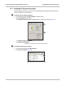
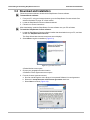

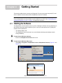
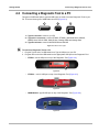
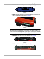
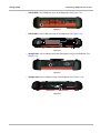
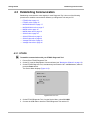
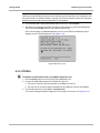
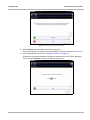
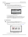
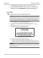
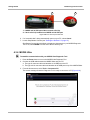
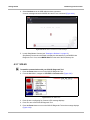
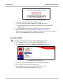
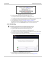
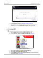
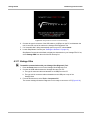
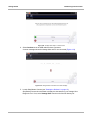
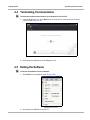
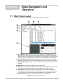
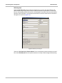
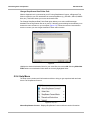

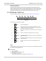
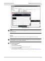
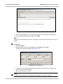
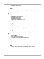
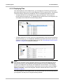
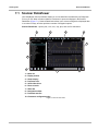
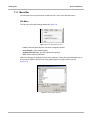
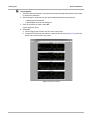
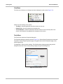
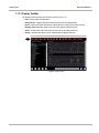
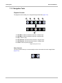
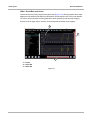
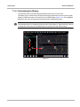
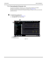
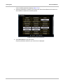
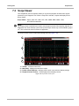
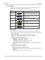
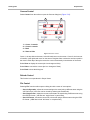
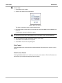
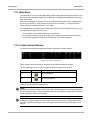
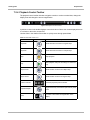
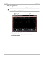
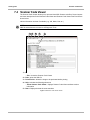
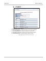
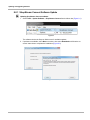
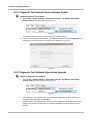
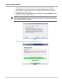
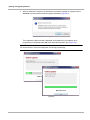

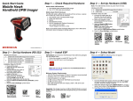

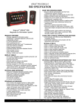


![VERUS PRO User Manual [3980kb PDF File] - Snap](http://vs1.manualzilla.com/store/data/005690474_1-9ff68923f14d7698ce72469cabae3990-150x150.png)