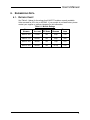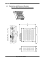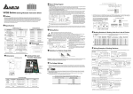
1
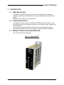
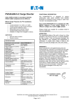
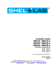
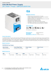
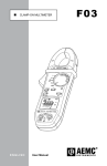
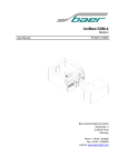
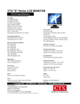
Model M3675T Dynamic Braking Control Module Customer Reference Manual TEL. (615) 244-2825 ● FAX (615) 244-2833 ● www.bonitron.com Bonitron, Inc. Bonitron, Inc. An Industry Leader in AC Drive Systems and Industrial Electronics OUR COMPANY Bonitron is an international supplier of power controls designed to improve the performance and reliability of electronic systems and variable frequency drives. Located in Nashville, Tennessee, and founded in 1962, Bonitron has gained a reputation for designing and manufacturing products with the highest possible degree of quality and reliability. Bonitron has all the necessary resources in-house for complete electronic product development and manufacturing. Engineering facilities include a CAD lab for circuit board design and engineering labs for prototype testing and evaluation. Production facilities include production areas for circuit board assembly, a machine tool and sheet metal shop for chassis fabrication, and a systems assembly and checkout area. With these assets, Bonitron is positioned to be a leader into the future while maintaining first class support for their current customer base. Worldwide sales of equipment are generated mainly by reputation and referrals. Our customer base includes all of the major drive manufacturers, their distributors, OEMs, end users, and many other satisfied companies. Equipment is installed throughout the United States as well as in Canada, Mexico, Costa Rica, Argentina, Brazil, Chile, Venezuela, Northern Ireland, the Netherlands, Spain, Hungary, Israel, Turkey, China, India, Indonesia, Singapore, Taiwan, and the Philippines. ii Bonitron, Inc. TALENTED PEOPLE MAKING GREAT PRODUCTS The engineering team at Bonitron has the background and expertise needed to design, develop, and manufacture the quality industrial systems demanded by today’s client. A strong academic background supported by continuing education is complemented by many years of hands-on field experience. Expertise encompasses a broad range of applications and engineering solutions such as modern power conversion design techniques and microprocessor-based controls. This insures a solution tailored to the specific needs of the client. A clear advantage that Bonitron has over many competitors is combined on-site engineering labs and manufacturing facilities. This allows the engineering team to have immediate access to and response from testing and manufacturing. This not only saves time during prototype development, but also is essential to providing only the best quality products. AC DRIVE OPTIONS In 1975, Bonitron began working with the AC inverter drive specialists at synthetic fiber plants to develop speed control systems that could be interfaced to their plant process computers. Since that time, Bonitron has developed AC drive option modules that help overcome many of the problems encountered in applications of modern AC variable frequency drives. Bonitron’s Ride-Thru module provides protection from AC line voltage sags while the Line Regen and Resistive Braking modules provide DC Bus regulation for over-voltage due to regenerated voltage. Bonitron AC drive modules are available to provide Undervoltage, Overvoltage, Line Side, Load Side, Maintenance, Power Quality, and Green / Sustainability solutions. These products are compatible with the drives of all major manufacturers and have become the standard in many industries including semiconductor, oil, and fiber. WORLD CLASS PRODUCTS Bonitron has developed over 3000 different modules and systems. Bonitron is willing and able to meet the unique specifications the client may request. Some Bonitron products include: • • • • • • • • • • • • Power Sag Ride-Thru Modules Power Outage Ride-Thru Modules Line Regen Modules Resistive Braking Modules Modular High Speed Precision AC Inverter Systems Inverter Upgrade Modules Multi-motor, Multi-phase Current Sensors Battery Production Charging Systems Data Acquisition Systems Process Controllers Temperature Control Systems RMS True Reading Digital Voltmeters, Ammeters, and Frequency Meters iii M3675T iv Table of Contents 1. INTRODUCTION ..........................................................................................................................1 1.1. Who Should Use ........................................................................................................................... 1 1.2. Purpose and Scope ........................................................................................................................ 1 1.3. Manual Version and Change Record ............................................................................................ 1 Figure 1-1: Model M3675T ......................................................................................................................... 1 2. PRODUCT DESCRIPTION ............................................................................................................3 2.1. Related Products ........................................................................................................................... 3 2.2. Part Number Breakdown .............................................................................................................. 3 Figure 2-1: Example of M3575T Part Number Breakdown ........................................................................ 3 Table 2-1: Control Voltage Rating Chart..................................................................................................... 3 2.3. General Specifications .................................................................................................................. 4 Table 2-2: General Specifications Chart ...................................................................................................... 4 2.4. General Precautions and Safety Warnings ................................................................................... 5 3. INSTALLATION INSTRUCTIONS ..................................................................................................7 3.1. 3.2. 3.3. 3.4. Environment ................................................................................................................................. 7 Unpacking ..................................................................................................................................... 7 Mounting ...................................................................................................................................... 7 Wiring and Customer Connections ............................................................................................... 7 Table 3-1: Power Wiring Specifications ...................................................................................................... 8 3.5. Typical Configuration................................................................................................................... 8 Figure 3-1: Typical Chassis Interconnection Diagram ................................................................................ 8 4. OPERATION ................................................................................................................................9 4.1. Functional Description ................................................................................................................. 9 4.2. Features......................................................................................................................................... 9 5. MAINTENANCE AND TROUBLESHOOTING ...............................................................................11 5.1. Troubleshooting .......................................................................................................................... 11 6. ENGINEERING DATA ................................................................................................................13 6.1. Ratings Chart .............................................................................................................................. 13 Table 6-1: Module Ratings ........................................................................................................................ 13 6.2. Dimensions and Mechanical Drawings ...................................................................................... 14 Figure 6-1: M3675T Chassis Dimensional Outline Drawing .................................................................... 14 v M3675T This page intentionally left blank. vi User’s Manual 1. INTRODUCTION 1.1. WHO SHOULD USE This manual is intended for use by anyone who is responsible for integrating, installing, maintaining, troubleshooting, or using this equipment with any AC drive system. Please keep this manual for future reference. 1.2. PURPOSE AND SCOPE This manual is a user’s guide for the Model 3675T Braking Control Module. It will provide the user with the necessary information to successfully install, integrate, and use the M3675T. In the event of any conflict between this document and any publication and/or documentation related to the AC drive system, the latter shall have precedence. 1.3. MANUAL VERSION AND CHANGE RECORD Rev 02d has minor format changes. Figure 1-1: Model M3675T 1 M3675T This page intentionally left blank. 2 User’s Manual 2. PRODUCT DESCRIPTION The need for dynamic braking control occurs in applications where the frequency of an AC motor at times exceeds that of the variable frequency drive controlling it. When this happens, the motor acts as a generator. The energy produced in these circumstances may cause the drive to trip on an over-voltage condition or cause the motor to build up heat or run with an excessively high volts/Hertz ratio. This regenerated energy must either be dissipated or returned to the power line. For applications where this condition occurs infrequently, dissipating the energy as heat through dynamic braking control can be the most cost-effective solution. The Model M3675T series of braking products is designed to provide dynamic braking control for applications utilizing a standard AC drive with a fixed DC bus. These modules have been designed for use with remotely mounted dynamic loads such as the M3675R-H100C or M3575R series of Dynamic Load Modules. 2.1. RELATED PRODUCTS The Model M3675R-H100C 96Ω/100W Braking Resistor and the M3575R series of Dynamic Load Modules are available for use with the M3675T Dynamic Braking Control Modules or with the drive’s integral braking control module. Contact your drive distributor for more information. 2.2. PART NUMBER BREAKDOWN Figure 2-1: Example of M3575T Part Number Breakdown M3675T H 10 BASE MODEL NUMBER AC DRIVE VOLTAGE RATING DC CURRENT RATING BASE MODEL NUMBER The Base Model Number, M3675T, indicates that the unit incorporates the braking transistor and its control circuitry only. An external braking resistor is required for proper function of the braking module. AC DRIVE VOLTAGE RATING The AC Voltage Rating of the braking unit should match the input AC line voltage to the AC drive used with the braking module. The AC Drive Voltage is indicated by a code letter. Table 2-1: Control Voltage Rating Chart RATING CODE LINE VOLTAGE INPUT U 115VAC L 230VAC E 380VAC H 460VAC 3 M3675T DC CURRENT RATING: The DC Current Rating indicates the maximum DC current level safely handled by the braking unit. All M3675T modules are rated for a maximum of 10 Amps DC at 20% duty cycle. 2.3. GENERAL SPECIFICATIONS Table 2-2: General Specifications Chart PARAMETER SPECIFICATION Adjustments Factory calibrated – no field adjustments necessary Drive DC bus Resistors TYPE-1 DC bus Active braking For use with the following drive systems: 115VAC 230VAC 380VAC 460VAC 10 Amps DC maximum (Use Bonitron M3575T for applications requiring higher current ratings) Connections Enclosure Panel Indicators Drive Voltage Braking Current 4 Peak Horsepower 2.5hp (for 115VAC drives) 5.0hp (for 230VAC drives) 7.5hp (for 380VAC drives) 10.0hp (for 460VAC drives) Duty Cycle 20% Maximum braking (Use Bonitron M3452 for applications requiring higher duty cycles) Maximum On-Time 15 seconds Control Power Derived from DC bus voltage Turn-On Voltage 190VDC (for 115VAC drives) 375VDC (for 230VAC drives) 620VDC (for 380VAC drives) 750VDC (for 460VAC drives) Turn-Off Voltage 180VDC (for 115VAC drives) 350VDC (for 230VAC drives) 600VDC (for 380VAC drives) 725VDC (for 460VAC drives) Storage Temp -20ºC to +65ºC Humidity Below 90% non-condensing Atmosphere Free of corrosive gas and dust User’s Manual 2.4. GENERAL PRECAUTIONS AND SAFETY WARNINGS HIGH DANGER! FAILURE TO HEED THESE WARNINGS MAY RESULT IN SERIOUS BODILY INJURY OR DEATH! THIS CAUTION! VOLTAGES MAY BE PRESENT! PRODUCT GENERATES HEAT DURING OPERATION. THIS PRODUCT SHOULD BE INSTALLED ACCORDINGLY NON-FLAMMABLE SURFACES WITH CLEARANCES OF LEAST TWO INCHES IN ALL DIRECTIONS. ON AT NO USER-SERVICEABLE PARTS ARE CONTAINED WITHIN INOPERABLE UNITS SHOULD BE THIS PRODUCT. REPLACED OR RETURNED FOR EVALUATION AND/OR REPAIR BY QUALIFIED TECHNICIANS BEFORE ATTEMPTING INSTALLATION OR REMOVAL OF THIS PRODUCT, BE SURE TO REVIEW ALL DRIVE AND/OR RESISTIVE LOAD DOCUMENTATION FOR PERTINENT SAFETY PRECAUTIONS. INSTALLATION AND/OR REMOVAL OF THIS PRODUCT SHOULD ONLY BE ACCOMPLISHED BY A QUALIFIED NATIONAL ELECTRICIAN IN ACCORDANCE WITH ELECTRICAL CODE OR EQUIVALENT REGULATIONS. ANY QUESTIONS AS TO APPLICATION, INSTALLATION OR SERVICE SAFETY SHOULD BE DIRECTED TO THE EQUIPMENT SUPPLIER. 5 M3675T This page intentionally left blank. 6 User’s Manual 3. INSTALLATION INSTRUCTIONS WARNING! Installation and/or removal of this product should only be performed by a qualified electrician in accordance with National Electrical Code or local codes and regulations. Proper installation of the Model M3675T Dynamic Braking Control Module should be accomplished following the steps outlined below. Be sure to refer to your AC drive’s instruction manual as you perform these steps. Please direct all installation inquiries that may arise during the installation and start up of this braking product to your supplier or system integrator. 3.1. ENVIRONMENT The installation site for the module should be chosen with several considerations in mind: • The mounting surface must be non-flammable, as the unit may generate high ambient temperatures during typical operation. • The unit will require a minimum clearance of two inches in all directions around it. • The unit will require adequate protection from the elements. 3.2. UNPACKING Upon receipt of this product, please verify that the product received matches the product that was ordered and that there is no obvious physical damage to the unit. If the wrong product was received or the product is damaged in any way, please contact the supplier from which the product was purchased. 3.3. MOUNTING Once the installation site has been selected as outlined above, the unit should be mounted in place using two ¼ inch diameter bolts or studs. Refer to Figure 6-1 to determine the correct mounting dimensions for your unit. 3.4. WIRING AND CUSTOMER CONNECTIONS This section provides information pertaining to the field connection of the DC bus inputs to the M3675T Dynamic Braking Module. Actual connection points and terminal numbers for the AC drive module will be found in the documentation provided with the drive. Be sure to review all pertinent drive and system documentation as well as the power wiring information in Section 3.4.1 before proceeding. 3.4.1. POWER WIRING WARNING! WARNING! Only qualified electricians should perform and maintain the interconnection wiring of this product. All wiring should be done in accordance with local codes. DC bus polarity must be observed! Connecting the DC bus with the polarity reversed will cause damage to the equipment! 7 M3675T For the maximum wire size accepted by the individual field connection terminals, refer to Table 3-1: Power Wiring Specifications. Wire types and sizes should be chosen in accordance with national and local electrical codes to meet the voltage and current levels present for your application. Minimum load resistance requirements listed in Table 6-1: Module Ratings in the Engineering Section of this manual MUST be followed when selecting a dynamic load for use with the M3675T unit. Figure 3-1 shows a typical interconnection of the M3675T with the M3575R Resistor Module. For interconnection with other load modules, refer to the documentation supplied with them. Table 3-1: Power Wiring Specifications MIN WIRE MAX WIRE AWG AWG DC+, DC─, RES+, RES─ 16 12 8 lb-in Ground 16 12 8 lb-in TERMINAL TORQUE 3.5. TYPICAL CONFIGURATION 8 Dwg #: 070247 Rev: 20070925 GND RES. - RES. + DC - DC + BRAKING DC BUS MODEL 3675 DRIVE BONITRON Figure 3-1: Typical Chassis Interconnection Diagram User’s Manual 4. OPERATION 4.1. FUNCTIONAL DESCRIPTION The M3675T Module controls the bus voltage of a variable frequency drive by transferring energy to a resistor. When the drive’s DC bus voltage exceeds a fixed setpoint, the Dynamic Braking Control Module’s control electronics turns on an IGBT transistor connecting a dynamic load across the DC bus. When the DC bus drops below another threshold, the IGBT turns off. The Turn-On setpoint is fixed at: 375VDC for 230VAC systems 620VDC for 380VAC systems 750VDC for 460VAC systems 940VDC for 575VAC systems 4.2. FEATURES For output and bus protection the M3675T includes a semiconductor fuse which limits the energy in the case of a bus or control fault. 4.2.1. INDICATORS 4.2.1.1. DC BUS The DC Bus indicator illuminates when the voltage between the DC+ and DC- terminals is greater than 50VDC. CAUTION 4.2.1.2. Do not use this light as an indication that the DC bus is safe to work on! Always check the DC bus with a working voltmeter before servicing equipment, as the DC bus light may be broken! CONTROL POWER This indicator illuminates when control power is applied to the unit, and indicates that the control circuit is functioning. 4.2.1.3. ACTIVE BRAKING This indicator illuminates when the chopper IGBT is on. When the drive is idle, this light should not be on. During braking, this light will be on or flashing, depending on the amount of braking energy. This light will also be on if the Bus Discharge input is active. 9 M3675T This page intentionally left blank. 10 User’s Manual 5. MAINTENANCE AND TROUBLESHOOTING 5.1. TROUBLESHOOTING If a problem occurs on start-up or during normal operation, refer to the problems described below. If a problem persists after following the steps below, contact the product supplier or your system integrator for assistance. Repairs or modifications to this equipment are to be performed by Bonitron approved personnel only. Any repair or modification to this equipment by personnel not approved by Bonitron will void any warranty remaining on this unit. GREEN DC BUS POWER LED DOES NOT COME ON Ensure proper DC Bus voltage at input terminals to the unit. If proper DC Bus voltage is present, return unit for repair or replace unit. RED ACTIVE BRAKING LED STAYS ON OR FLASHES DURING MOTORING OPERATION Ensure that the voltage rating of M3675T is the same as the AC Drive. If the voltage rating is the same, ensure that the line voltage to the AC Drive is correct. If line voltage is abnormally high or low, the unit may require special calibration adjustments. Contact the product supplier or your system integrator for assistance. If correct line voltage is present on the AC Drive and the M3675T module is rated for the same line voltage as the AC Drive, return unit for repair or replace unit. DRIVE TRIPS ON OVER-VOLTAGE OR SELF-LIMITS ITS DECEL RATE Ensure that the Green DC Bus Power LED is ON (see above). Ensure that the proper dynamic load value is connected to the M3675T unit and that the maximum current rating is not exceeded. Most AC drives are capable of 150-200% output. If the AC Drive continues to trip and the application has been thoroughly reviewed, contact Bonitron. 11 M3675T This page intentionally left blank. 12 User’s Manual 6. ENGINEERING DATA 6.1. RATINGS CHART See Table 6-1 below for the ratings for all M3675T modules currently available. Units are rated for 20% duty or 2A RMS. If your module is not listed below, please contact your supplier or systems integrator for this information. Table 6-1: Module Ratings VOLTAGE MAX DC AMPS BRAKING MINIMUM LOAD M3675T-U10 115VAC 10A 2.5hp 19Ω M3675T-L10 230VAC 10A 5.0hp 38Ω M3675T-E10 380VAC 10A 7.5hp 62Ω M3675T-H10 460VAC 10A 10.0hp 75Ω PART NUMBER DRIVE MAX 13 M3675T 6.2. DIMENSIONS AND MECHANICAL DRAWINGS Figure 6-1: M3675T Chassis Dimensional Outline Drawing 14 Dwg #: 070246 Rev: 20070925 User’s Manual NOTES 15 M3675T This page intentionally left blank 16 D_M3675T_CMAN_VALL_02d 521 Fairground Court ● Nashville, Tennessee 37211 (615) 244-2825 ● FAX (615) 244-2823 ● www.bonitron.com 02/14/2011