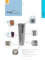
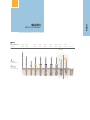
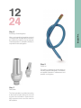
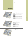
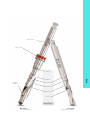
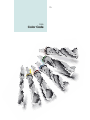
1
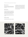
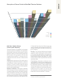
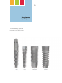
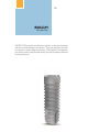
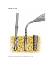
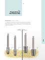
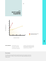
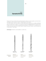
MIS System Guide | 2010
®
User Manual
© MIS Corporation. All Rights Reserved.
Published by MIS, which reserves the right to modify the
products described in this manual as well as to revise
this publication at any time and without informing any
person of such revision or change. All rights reserved. No
part of this publication may be reproduced, transcribed,
stored in an electronic retrieval system,translated to any
language or computer language, or transmitted in any form
whatsoever without the written consent of the publisher.
Questions, comments or requests will be addressed
promptly by contacting MIS specialists directly through
our e-mailing address: [email protected].
MIS’ website can be accessed at www.mis-implants.com.
This online site highlights current products and reflects
all new discoveries and developments.
Note: This User Manual is for educational use only.
MIS Implants Technologies Ltd. produces an oral implant system
that includes self-tapping dental implants in a wide range
of sizes. These implants, currently being used successfully
worldwide, provide a solution to partial and full edentulism.
All implants go through gamma-irradiation and are supplied
sterile in specially designed tubes. The implants are selftapping with threads designed to provide secure primary
fixation and favorable distribution of the loading forces. The
MIS Implants system is manufactured from titanium alloys.
MIS Implants Technologies Ltd. is vigilant about maintaining
the high quality of its products as well as developing new
products in the fields of dental implants, abutments and surgical
kit components.
MIS’s Quality System complies with international quality
standards: ISO 13485:2003 - Quality Management System
for Medical Devices, ISO 9001: 2008 – Quality Management
System and CE Directive for Medical Devices 93/42/EEC. MIS’s
products are cleared for marketing in the USA and CE approved.
Overview
6.Introduction
7. Raw Material
8. Finite Elements Test
10. Implant Treatment
11. Implant Surface
Overview.
MIS concept
13. Roughness Measurements
14. XPS Analysis
15. In Vitro Test
16.Histology
6.
Overview
Introduction
MIS is a dynamic, high-tech research and production company. It develops
and manufactures a comprehensive range of dental implants that provide
long-lasting successful solutions to partial and full edentulism. The MIS
Implants system combines several advantageous elements in order to
achieve good primary stability and successful osseointegration. The qualities
that contribute to successful osseointegration have been determined by
various researchers to include: choice of raw material, macrostructure,
microstructure and surface cleaning. In this chapter we present these factors
and others that have been considered and/or included in the implants
manufacturing process. MIS upholds its high standards, relevant to these
factors, through comprehensive examinations and tests.
The implant surface is tested and has satisfied or exceeded all requirements
for implants. The tests are carried out in some of the world’s best-known
research institutions. The main tests that MIS implants undergo are:
- Mechanical test
- XPS Analysis
- Roughness
- Surface analysis
- SEM
- Cytotoxicity
- Sterility
- Torque removal value
- Histology
Overview
7.
Overview
Raw Material
All MIS implants are made of biocompatible
medical grade Titanium alloy.
Titanium and its alloys are highly successful materials
for the fabrication of dental implants because of
their favorable combination of properties such as;
low specific weight, high strength to weight ratio,
high modulus of elasticity, very high corrosion
resistance and excellent general biocompatibility.
The excellent biocompatibility and osseointegration
capabilities of titanium are related to a variety
of favorable properties of the material and its
surface, including the following:
the impedance and polarization resistance (Rp)
values of the metals. SEM micrographs, and an
equivalent circuit confirmed this behavior.
Modification of the surface by thermal treatment
improves corrosion resistance, as a protective
titanium layer is formed on the surface. Another
quality that makes titanium uniquely suited to
implants is that the titanium oxide layer is stable
over a very large range of physiologic pH, and
therefore there is no release of free ions into the
tissue. Titanium alloys increase the mechanical
strength by 30%-40% over pure titanium.
-A dense, highly resistant passive oxide film
that protects the underlying metal from (further)
oxidation and corrosion.
-A very low dissolution rate of the oxide film
and an extremely low concentration of charged
titanium corrosion products.
Biocompatibility is a complex property that
involves physical, chemical, biological,
medical and design aspects. It is important
to note that the corrosion resistance of
the titanium alloy is directly related to
the surface condition before corrosion
evaluation, and is a determining factor
in the electrochemical behavior of
this alloy. A study of titanium and
its alloys, demonstrated that the
biocompatibility of metal implants
was related to their electrochemical
characterization. The results
showed that the presence of cells
on metals led to an increase in
Titanium alloys increase the
mechanical strength by 30%-40%
over pure titanium.
8.
Overview
Finite
Elements Test
The finite elements method (FEM) provides additional information
about implants. Implants analysis by FEM is a test that is commonly
used for the localization and prediction of a mechanical system
failures. A structure analysis enables the determination of effects
such as deformations, strains and stresses which are caused by
applied structure loads. The safety factor is calculated using the
maximum stress failure theory for ductile materials. The stress limit
is specified by the tensile yield strength of the material.
The benefits of FEM include increased accuracy, enhanced
design and better insight into critical design parameters. The
results of these tests show that the greatest stress occurs in
the neck rather than the apex of the implant.
MF4
MF7
Overview
10.
Overview
Implant
Treatment
Structure (Raw Material)
Roughness
(Macro & Micro)
Titanium’s rough surface provides many points for
mechanical anchorage and increases the envelope
surface by two to three times.
Subtraction
Advantage: no degradation and separation
of the coating.
Sandblast
The combination of the two methods induces macro
and microstructure that is optimal for cell adhesion.
Acid Etching
MIS Surface Treatment
Overview
11.
Overview
Implant Surface
The contact surface of a dental implant is a very important
aspect of the implant’s long-term success. This phenomenon
is known as osseointegration. The opposing reaction of the
bone to the implant is determined by morphology, chemical
composition, load and the characteristics of the implant
surface. It is achieved by topography and morphology, nano
surface elements and bone reaction tests.
SEM image of the bone-to-implant interface
SEM image showing an osteoblast
At MIS all of the following aspects have been considered:
Macrostructure
The geometric design of the body and thread
profile of the implant act to increase the primary
stability and to distribute the axial forces
of occlusion.
of 100 microns, and is in turn covered with
an additional one-molecule-thick layer of
contaminants containing sodium, silicon,
magnesium, fluorine, etc. The cleaning process is
multi- staged in order to ensure the quality of the
product. The success of the implant is determined
its geometric shape, by its microscopic texture
and its surface quality.
Microstructure
The surface roughness and microgeometry
of titanium are achieved by sandblasting and
acid-etching. This process increases the surface
envelope of the implant. Blasted surfaces
demonstrate more bone to implant surface contact
when compared with machined surfaces.
*This advanced geometric design and surface
morphology are the factors that create successful
implants.
Surface cleaning
The implant surface consists of titanium
oxide (Ti O2), which can reach a thickness
x2000
x5000
Overview
13.
Overview
Roughness
Measurements
Roughness or rugosity is a measure of the small-scale variations in the height of a
physical surface. A rough texture allows the trapping of different elements and increase the
envelope surface. A high tendency for high roughness improves mechanical anchorage
and increases the envelope surface by two to three times.
AFM Test
MIS Surface topography
Roughness Measurement
The arithmetic average of the deviation Ra is the most commonly used measure
for surface roughness. The microgeometry of MIS implants meets the roughness
recommended in the international literature.
Instrument:
Parthometer M1
(MAHR)
Ra 2.2µm Rz 14.6µm Rmax 15µm
Lt 5.6mm
Lc 0.8mm
Pc (0.5-0.5) 165/c
14.
Overview
XPS Analysis
For surface analysis the samples were irradiated
with monochromatic X-rays. Survey spectra
were recorded with a pass energy of 100 eV,
allowing the surface chemical composition to
be determined. The atomic concentrations were
calculated using elemental sensitivity factors,
without applying any standardization procedure.
The core level binding energies of the different
peaks were normalized by setting the binding
energy for the Cls to 284.5 eV. For each of the
screws, one flat edge area, marked as #1, was
analyzed in the as-received state only.
Table 1 XPS Atomic Concentrations (%) for LOT 83
Implants
MF7-13375, thread area 1
C
Ti
O
24.31 19.45 52.71
N
-
MF7-13375, thread area 2
27.78 16.11 51.31 0.21
Ca
-
Si S Cl Na Al Cu Mg
- - 0.12 - 3.08 0.05 -
-
0.78 3.60
-
-
P
V
- 0.33
-
0.16
Table 2 Ti Oxide Thickness (nm) for LOT 83
Samples
Oxide Thickness (nm)
MF7-13375, thread area 1
6.5
Table 1 XPS Atomic Concentrations (%) for LOT 41903
Implants
MF7-13375, thread area 1
C
Ti
O
N Ca
25.71 17.60 52.22 1.99 -
Si S Cl
- - -
Na Al Cu Mg F P ZN
- 1.96 - 0.51 - - -
MF7-13375, thread area 2
28.66 14.88 52.62 0.84
-
--
-
-
-
2.12
-
0.87 - -
-
* Instrument: VG Scientific Sigma Probe
X-Ray Source: Monochromatic Al K&, 1486.6eV
X-Ray Beam Size: 400 µm
Interpretation of Results
No strange elements or traces thereof were identified. This means that the surface treatment (etching) did
not leave any undesired effects. The implants were classified as normal based on the C/Ti ratio.
Overview
Absorption of Serum Protein to Modified Titanium Surfaces
20
15
10
5
Albumin
IGG
Fibronectin
Fibrinogen
0
MACHINE
BIOCOM
M.N. Sela, L.Badihi, G.Rosen
D.Kohavi and D. Steinberg
The use of Titanium (Ti) implants is a innovative
clinical procedure in dentistry. The absorbtion
of biological molecules to the implant’s surface
triggers a sequence of events that can determine
the outcome of this procedure. Clinical data
suggests that modified Ti surfaces play an
important role in the success or failure of the
implant.
Objective: the purpose of this study was to
investigate the interaction between Ti implants
with different surface properties and serum
proteins, in order to find the optimal implant
surfaces that may improve the osseointegration
process and implant intake.
Materials & Methods: Ti disks (6mm in diameter)
with two types of surface modifications were
compared: Machined and Sandblast together
with Acid-Etched. The disks were coated with
mixtures of Human Serum Albumin conjugated
with fluorescein (HAS-FITC). Following incubation,
the coat was removed from the disks by SDS.
SEVEN
A Confocal Scanning Laser Microscope was
used to visualize and measure the HAS-FITC
coat and the degree of protein removal from
the Ti surfaces.
Results: The Confocal Microscope images
revealed a significantly higher amount of HASFITC coat on the rough disks, as compared with
the machined disks. Furthermore, under similar
experimental conditions, less HAS-FITC could
be removed from the rough disks than from the
machined disks.
Conclusions: Absorption of albumin to the
rough treated Ti surface is both qualitatively and
quantitatively far more intense, as compared with
the machined surfaces. Further studies of the
chemical and physical characterization of the
modified Ti surfaces are underway. Moreover,
additional serum proteins, as well as oral
microorganisms, are being examined for their
interactions with the modified Ti surfaces.
Hebrew University
Jerusalem, Israel, IADR, August 03, 2004
16.
Overview
Histology
MIS implants undergo routine testing, including histology and
microsity tests, in order to evaluate the amount and quality of
bone integrated on the implant as well as other indications
for osseointegration. The osseointegration's success is
determined through the many contact areas of the implant
surface. The following report characterizes the MIS implant
surface as indicated by the various test results.
Light Microscopy
Micro CT
The sample was analyzed by micro CT before
histological treatment was analyzed by micro CT.
X-ray micro-computed tomography (SkyScan
1072, Belgium). The X-ray source was operated
at 100 kV and a current of 98 µA. The sample
was rotated 180° with a rotation step of 0.90°,
an acquisition time of 5.6 s per scan and a pixel
size of 11.8 µm.
Three-dimensional reconstructions were
then performed with the 3D Creator SkyScan
software.
Histology
Embedding
Samples were fixed in a 10% formalin solution,
dehydrated in ascending graded ethanol
(70, 80, 90, 95, 100%) and pure acetone, and
then impregnated and embedded in PMMA
(methyl methylmetacrylate).
The Polymerization was obtained with
a temperature increase from 20°C to 80°C.
X-ray microtography
Results and Discussion
The histotology and microscopy results show
the following osseointegration contact areas
between the bone and implant surfaces:
Light Microscopy
Full osteointegration was observed. Bone contact
was achieved both in the front of the wire and
at the top of the implant. Bone ingrowth with
bone trabeculae was also observed.
Micro CT
Bone osseointegration was observed along
all the 3D axes. Bone trabeculae are directly
in contact with the wires.
Conclusion
In conclusion, it appears that larger bone
ingrowth and bone contact was observed in
the implants.
Overview
Materials and Methods
Implants
20. Implant System
22. UNO
Implants.
30. BIOCOM
38. SEVEN
20.
Implants
Implant System
The MIS leading implants:
UNO, BIOCOM and SEVEN
UNO
ONE PIECE
UNO
NARROW
BIOCOM
SEVEN
The innovative design of our implants, combined
with our simple and fast insertion procedures,
provides an easy to use system that ensures
successful results.
The wide range of MIS implant lines provides a
variety of clinical solutions for the reconstruction of
a single tooth, screw-retained or cemented fixed
bridges, and overdentures. Furthermore, MIS
Note: The selection of MIS implants and procedures
is a recommendation only, and cannot replace the
judgment and the experience of the surgeon. This
recommedation shoud be used as a guide only.
implants can be used in any surgical and bone
augmentation procedures, from the simplest to
the most intricate. MIS implants are made of highquality materials under very strict quality control
procedures with a 100% inspection rate.
All MIS implants are made of biocompatible
medical-grade titanium, and their surfaces undergo
dual-acid-etching procedures.
Implants
MIS has developed a range of unique implants
and tools to assist in the simplification of the
implantation process and to ensure both efficiency
and success while minimizing risks.
22.
Introduction
Each of these unique implants is specifically engineered for use in narrow
ridges and tight spaces. The insertion of the UNO implant is a quick and
simple one-stage procedure. Due to their innovative geometries and
advanced surface morphology, these unique implants offer high primary
stability. These versatile implants can be used to restore single crowns and
anterior cemented bridges.
UNO NARROW
UNO ONE PIECE
23.
Implants
One Piece
Fixture - Technical Info
2.1mm
5º
5º
8
1
2.1mm
7(A)
2
0.6mm
7(B)
3
6
5
Length
2mm
3
4
120º
1
Abutment with squared crown
2
Deep threads 0.6mm
3
Dual thread of 2mm
4
Cutting Apex
5
Two spiral channls
6Implant length
7
Surface: (A) acid etched (B) sandblasted and acid etched
8
Maximum anguled position 10º
24.
NARROW
Fixture - Technical Info
2.7mm
7
1
6
2mm
2
5
3
0.6mm
Length
4
3
1
External Hexagon 2.7 mm
2
Deep threads 0.6mm
3
Cutting Apex
4
Two spiral channls
5Implant length
6
Dual thread of 2mm
7
Surface- sandblasted and acid etched
120º
Implants
26.
Features
Features
Versatility
A mono block screw type implant.
Especially designed for narrow ridges and
tight spaces.
The MIS UNO is indicated for use in narrow
ridges and tight places, such as maxillary
lateral and mandibular incisors. The MIS
UNO’s versatility enables the clinician to use
the implant for single-tooth, partial-denture
and over-denture restorations.
The geometric is encompassed in the
unique design.
Bone-to-implant contact maximized.
Enables a fast, thread–form free insertion
and initial stability.
Advantages
Simple
MIS UNO’s specially designed tools and simple
procedure ensure a worry-free restoration for
the clinician.
Easy
An innovative design with increased insertion
speed making the MIS UNO an easy implant
to insert.
Stability
The MIS UNO design ensures maximum
strength and stability for the implant and
restorative parts.
Long-lasting
Due to innovative geometry and advanced
surface treatment, the MIS UNO provides high
initial stability and a long-lasting restorative
result.
Surface
The surface roughness and microgeometry
of Titanium Alloy Ti 6Al-4V ELI are achieved
by sand blasting and acid etching. Blasted
surfaces demonstrate more bone to implant
surface contact compared with machined
surfaces.
Implants
27.
Implant Range
One piece
Length
Type
10mm
11.50mm
13mm
16mm
MO1-10300
MO1-11300
MO1-13300
MO1-16300
MO1-10350
MO1-11350
MO1-13350
MO1-16350
MO2-10300
MO2-11300
MO2-13300
MO2-16300
3mm
One Piece
Implant
3.50mm
One Piece
Implant
Narrow
3mm
Narrow Two
Piece Implant
MB-NR005
UNO Ball
Anchor Screws
0.50mm
MB-NR015
1.50mm
MB-NR025
2.50mm
28.
Ø3mm / Ø3.5mm
One Piece Procedure
Ø 3mm
Drill Speed (RPM)
12001500
9001200
Diameter
Ø1.90
Ø2
Drill Speed (RPM)
12001500
9001200
Diameter
Ø1.90
Ø2
Ø 3.50mm
Ø2
Ø2
700900
15-20
Ø2.40
Ø3
700900
400700
15-20
Ø2.40
Ø3
Ø3.50
29.
Ø 3mm
Drill Speed (RPM)
12001500
9001200
Diameter
Ø1.90
Ø2
Any procedure recommended by
MIS cannot replace the judgment
and the experience of the surgeon.
Implants
Ø3mm Narrow
Procedure
Ø2
700900
15-25
Ø2.40
Ø3
30.
Introduction
MIS BIOCOM implants are titanium cylinder screw type implants
with an internal hexagon connection. They are designed for both
two-stage or single-stage procedures. The implant is self-tapping
and has a unique wide thread design as well as tapered threads
at the apical part.
Implants
31.
Fixture - Technical Info
2.45mm
5
0.8mm
1
4
2
3
1
Internal Hexagon 2.45 mm
2
Cutting Flutes
3
Domed Apex
4
Surface - sandblasted and acid etched
5
Thread lead 0.8 mm
32.
Features
Features
The BIOCOM implants are self tapping with
threads that are designed to provide secure
primary fixation.
A wide range of restoration parts.
Suitable for t wo-stage implant
procedures.
Available in 3.30mm, 3.75mm, 4.20mm,
5mm and 6mm diameters and lengths of
6mm, 8mm, 10mm, 11.50mm, 13mm and
16mm (see page 25).
Surface
The surface roughness and microgeometry
of Titanium Alloy Ti 6Al-4V ELI are achieved
by sand blasting and acid etching. Blasted
surfaces demonstrate more bone-to-implant
surface contact compared with machined
surfaces.
Self-Tapping
The three cutting flutes are designed to engage
the bone immediately during placement
and ensure multi-directional locking. The
tapping head cuts into the bone with far
less friction due to the relief design of the
cutting edge.
33.
Length
6mm
8mm
10mm
11.50mm
13mm
16mm
MF4-10330
MF4-11330
MF4-13330
MF4-16330
MF4-08375
MF4-10375
MF4-11375
MF4-13375
MF4-16375
MF4-06420
MF4-08420
MF4-10420
MF4-11420
MF4-13420
MF4-16420
MF4-06500
MF4-08500
MF4-10500
MF4-11500
MF4-13500
MF4-16500
MF4-06600
MF4-08600
MF4-10600
MF4-11600
MF4-13600
Type
Ø3.30mm
Screw type
implant narrow
platform
Ø3.75mm
Screw type
implant standard
platform
Ø4.20mm
Screw type
implant standard
platform
Ø5mm
Screw type
implant wide
platform
Ø6mm
Screw type
implant wide
platform
* All implants include the cover screw.
Implants
Implant Range
34.
Ø 3.30mm / Ø 3.75mm
Procedure
* Recommended insertion torque is: 35-60 Ncm.
Ø 3.30mm
12001500
Drill Speed (RPM)
Diameter
Ø1.90
9001200
500700
200500
Ø2
Ø2.80
Ø2.80 Ø3.30 Ø3.30
Ø2
15-25
1
1
Countersink
(MT-GDN33)
for bone type 1&2
Ø 3.75mm
Drill Speed (RPM)
12001500
9001200
Diameter
Ø1.90
Ø2
Ø2
500700
400700
200500
15-25
Ø2.80
Ø3.20 Ø3.20
Ø3.75
Ø3.75
1
1
Countersink
(MT-GDN33)
for bone type 1&2
Any procedure recommended
by MIS cannot replace the
judgment and the experience
of the surgeon.
35.
Implants
Ø4.20mm / Ø5mm
Procedure
* Recommended insertion torque is: 35-60 Ncm.
Ø 4.20mm
Drill Speed (RPM)
12001500
9001200
Diameter
Ø1.90
Ø2
Ø2
500700
400700
400600
Ø2.80
Ø3.20
Ø3.80
200500
Ø3.80 Ø4.20
15-25
Ø4.20
1
1
Countersink
(MT-GDN33)
for bone type 1&2
Ø 5mm
Drill Speed (RPM)
1200- 9001500 1200
Diameter
Ø1.90 Ø2
Ø2
500700
400700
400600
400600
Ø2.80
Ø3.20
Ø3.80
Ø4.50
Ø4.50
1
1
Countersink
(MT-GDN50)
for bone type 1&2
200500
15-25
Ø5
Ø5
36.
Ø 6mm Procedure
* Recommended insertion torque is: 35-60 Ncm.
Ø 6mm
Drill Speed
(RPM)
1200- 9001500 1200
Diameter
Ø1.90 Ø2
Ø2
500700
400700
400600
400600
300500
300500
200500
15-25
Ø2.80
Ø3.20
Ø3.80
Ø4.50
Ø5
Ø5.50 Ø5.50
Ø6
Ø6
1
1
Countersink
(MT-GDN50)
for bone type 1&2
38.
Introduction
The MIS self-tapping SEVEN implants are specially designed for
implantation in a wide range of bone types and bone augmentation
procedures. Their geometric design includes dual threads, three
spiral channels stemming from the apex, micro rings on the
implant neck and a changing thread thickness along the implant.
All MIS SEVEN implants are supplied with a single use final drill
for reducing the heat produced during drilling, which results in an
improved osseointegration.
WIDE
STANDARD
Fixture - Technical Info
2.45mm
1
0.3mm
7
0.1mm
2
6
2.40mm
3
5
4
1
Standard / wide: 2.45mm Int. hex. connection
2
Conical body
3
Surface - sandblasted+acid etched
4
Three spiral channels
5
Domed apex
6
Standard / wide: Dual thread of 2.40mm
7
Micro-rings (0.1x0.3mm)
Implants
39.
40.
NARROW
Fixture - Technical Info
2.10mm
1
0.3mm
7
0.1mm
2
6
2mm
3
5
4
1
Narrow: 2.10mm Int. hex. connection
2
Conical body
3
Surface - sandblasted+acid etched
4
Two spiral channels
5
Domed apex
6
Narrow: Dual thread of 2mm
7
Micro-rings (0.1x0.3mm)
Implants
41.
Features
Features
The SEVEN implant is designed to suit a wide
range of bone types and bone augmentation
procedures.
A specially designed drill ensures short and
safe drilling procedures.
A double thread of 2.40mm increases the
implant’s insertion speed.
It has self-tapping capability.
It has three spiral channels for improved
integration.
The micro-rings (0.1x0.3mm) on the implant’s
neck reduce the shear stress in the crest
zone.
The changes in the thickness of the thread
(0.15-0.4 mm) improve bone compression.
The SEVEN implants are available in 3.30mm,
3.75mm, 4.20mm, 5mm and 6mm diameters
and 6mm, 8mm, 10mm, 11.50mm, 13mm
and 16mm lengths.
Successful
The SEVEN implant has a high success rate
as a result of its advanced geometric design
and new surface morphology.
Forgiving
SEVEN is designed for implantation in a wide
range of bone types and bone augmentation
procedures.
Simple
A specially designed final drill is supplied
with every implant, allowing a short and safe
drilling procedure.
Easy
Increased insertion speed is provided by
a dual thread of 2.40mm, combined with a
self-drilling capability.
Primary Stability
The thread thickness changes from the apex
to the neck with the same pitch, improving
the compression of the bone during insertion.
Micro-rings on the implant’s neck provide
better initial stability by improving the interfacial
shear strength at the crest zone.
Minimal Bone Resorption
The surface roughness over the entire body,
the unique surface morphology, together with
the micro-rings at the implants neck, prevents
bone resorption at the implant’s neck.
Self-Tapping
SEVEN cuts its own threads during implantation,
minimizing friction-generated heat. Three spiral
channels running the length of the fixture fill
in with bone chips during implantation to
improve integration.
42.
Implant Range
Length
6mm
8mm
10mm
11.50mm
13mm
16mm
MF7-10330
MF7-11330
MF7-13330
MF7-16330
MF7-08375
MF7-10375
MF7-11375
MF7-13375
MF7-16375
MF7-06420
MF7-08420
MF7-10420
MF7-11420
MF7-13420
MF7-16420
MF7-06500
MF7-08500
MF7-10500
MF7-11500
MF7-13500
MF7-16500
MF7-06600
MF7-08600
MF7-10600
MF7-11600
MF7-13600
Type
3.30mm
Screw type
implant narrow
platform
3.75mm
Screw type
implant standard
platform
4.20mm
Screw type
implant standard
platform
5mm
Screw type
implant wide
platform
6mm
Screw type
implant wide
platform
* All implants include the cover screw and final drill.
43.
Implants
Ø 3.30mm / Ø3.75mm
Procedure
* Recommended insertion torque is: 35-60 Ncm.
Ø 3.30mm
Drill Speed (RPM)
1200- 9001500 1200
Diameter
Ø1.90 Ø2
Ø 3.75mm
Drill Speed (RPM)
1200- 9001500 1200
Diameter
Ø1.90 Ø2
Ø2
Ø2
500700
200400
Ø2.40
Ø2.20
Ø3.20
Ø3.30
500700
200400
300500
Ø2.80
Ø2.80 Ø2.80 Ø3.75
Ø3.60 Ø3.60
15-25
OR
2
1
Final drill
For bone type 1&2
2
Countersink
(MT-GDN33)
For bone type 3&4
Any procedure recommended
by MIS cannot replace the
judgment and the experience
of the surgeon.
1
15-25
44.
Ø 4.20mm / Ø 5mm
Procedure
* Recommended insertion torque is: 35-60 Ncm.
Ø 4.20mm
Drill Speed (RPM)
1200- 9001500 1200
Diameter
Ø1.90 Ø2
500700
Ø2
400700
200400
Ø2.80 Ø3.20 Ø3.30
Ø4.10
200500
15-25
Ø4.20
Ø4.20
OR
2
1
1
Final drill
For bone type 1&2
2
Countersink
(MT-GDN33)
For bone type 3&4
Ø 5mm
Drill Speed (RPM)
1200- 9001500 1200
Diameter
Ø1.90 Ø2
Ø2
500700
400700
400600
200400
200500
15-25
Ø2.80
Ø3.20
Ø3.80
Ø4.10
Ø 4.90
Ø5
Ø5
OR
2
1
1
Final drill
For bone type 1&2
2
Countersink
(MT-GDN50)
For bone type 3&4
Implants
Ø6mm Procedure
* Recommended insertion torque is: 35-60 Ncm.
Ø6mm
Drill Speed
(RPM)
1200- 9001500 1200
Diameter
Ø1.90 Ø2
Ø2
500700
400700
400600
400600
300- 200500 400
200500
15-25
Ø2.80
Ø3.20
Ø3.80
Ø4.50
Ø5
Ø6
Ø6
Ø 5.10
Ø5.90
OR
1
Final drill
For bone type 1&2
2
Countersink
(MT-GDN50)
For bone type 3&4
1
2
Surgical Pro.
Surgical
Procedures.
For MIS Implants
48. Indications & Contraindications
50. Step by Step Protocol
48.
Surgical Procedures
Indications and
Contraindications
Indications
Adequate bone is needed to support the
implant with width and height being the
primary dimensions of concern. The obligatory
bone dimension for implant placement in a
chosen site may be extracted for adequate
radiological techniques used in implant
dentistry.
In addition a very careful evaluation has to
be made as to the location of vital blood
vessels, nerves, maxillary sinus, soft tissue
spaces, and their relation to the site planned
for implant placement.
creatinine or serum calcium. Patients
with diabetes or cardiovascular disease
are contraindicated. Hypertension above
110/170 mmHg, osteoportic crush fractures,
respiratory disease, thyroid or parathyroid
disease should be excluded from treatment.
Patients with diagnosed malignancy in the
past five years and those with nodular
enlargements, tenderness or unexplained
lumps or masses of the head or neck should
not be treated. Implanting procedures should
not be performed on persons with active
osteolitic, inflammatory or infectious processes
in the implantation site.
The following outline lists the
contraindications:
- Debilitating or uncontrolled disease.
- Pregnancy, Hemophilia, Granulocytopenia
or other bleeding problems, steroid use,
Prophylactic antibiotics, Brittle diabetes,
Ehler-Danlos syndrome.
Contraindications
The contraindications customary in oral
surgery with other implant materials should
be observed. These include patients taking
corticosteroids, anticoagulants or anticonvulsant
and those receiving radiation or other
Immunosuppressive therapy. Lactating
or pregnant women are not candidates,
nor are patients with abnormal laboratory
values for BUN,
- Osteoradionecrosis, renal failure, Organ transplantation anticoagulation
therapy.
- Unexplained hypersensitivity, Fibrous
dysplasia, Regional enteritis.
infections in susceptible individuals, including
those with body part replacement. Existing
natural dentition may be compromised by
improper implant placement.
Other Contraindications
Conditions, diseases, or treatments that
severely compromise healing, including
radiation therapy.
The following outline lists organ systems with
corresponding pathophysiological problems
that may influence risks:
Poor patient motivation.
a. Cardiovascular failure, Coronary artery
disease, Arrhythmias.
b. Respiratory, chronic obstructive pulmonary disease.
Unrealistic patient expectations.
c. Gastrointestinal, Hepatitis, Malabsorption,
Inflammatory bowel disease.
Unattainable prosthodontic reconstruction.
d. Genitourinary chronic renal failure.
Inability of patient to manage oral hygiene.
e. Enducrine, Diabetes, Thyroid disease,
Pituitary/adrenal disordes.
Patient hypersensitivity to specific components
of the implants.
f. Hematological, Anemia, Leukemia,
Bleeding clotting disorders.
g. Musculoskeletal, Arthritis,
Osteoporosis.
h. Neurological, Stroke, Palsy, Mental
retardation.
Risks
Risks associated with the surgical procedure
fall into four broad categories:
1. Immediate anesthetic and surgical
risks.
2. Psychological and psychiatric risks.
3. Medical threats to long-term retention.
4. Long-term deleterious effects of implants
on health.
The risks may include:
Inadvertent perforation of the nasal and
maxillary sinus, local and systemic infections,
perforation into soft tissue spaces, and nerve
injury. Temporary conditions that might result
from implant placement may include pain
and swelling, speech problems and gingivitis.
Long-term problems may include nerve,
local or systemic bacterial infections, and
Important Warning
Lack of adequate practitioner training is
a major risk factor in the success of the
implant procedure and might endanger
patient health. Therefore, no implantation
should be performed without prior adequate
training from a certified institute.
Precautions
1. The implant is supplied for one time use.
DO NOT RESTERILIZE.
2. Use of implant does not require any unusual
preoperative antibiotic prophilaxis.
Surgical Pro.
Psychiatric disorders that interfere with patient
understanding and compliance with the
necessary procedure.
50.
Surgical Procedures
Step by Step
Protocol
The surgical manual is designed to provide an overview of the
presurgical and surgical procedures applicable to the MIS dental
implant system. Successful implantation requires a combination
of several factors. This step by step protocol is provided to ensure
that the correct surgical procedures are followed.
affecting the jaws; hypersensitivity to specific
implant components; psychiatric or personality
disorders that limit or interfere with patient
understanding and compliance.
Caution & Additional Tests
Step 1.
Patient Selection
(General medical history)
Patients must be carefully selected for surgery.
Medical histories should be evaluated for
indications and contra-indications. Medical
contra-indications includes: immunodeficiency
or immunosuppressive treatment; evolving or
active malignancy or following head and neck
radiation; poorly controlled diabetes or other
hormonal disorders; blood dyscrasias and
serious bleeding disorders; recent myocardial
infarction, severe cardiac insufficiency and
valve pathology; general bone diseases
Caution and additional tests should be
used in the following cases: patients with
preexisting myocardial disorders, anticoagulant therapy; arrythmias and valvular
pathology; auto-immune diseases; pregnancy,
alcoholism; any respiratory, urinary, gastrointestinal, neurological, hematological,
endocrine or other systemic disorders and
patients taking bisphosphate medication as
a treatment for osteoporosis, mucocutaneus
disorder. It is recommended, in cases
with questionable medical histories, to
consult with the patient’s general practitioner
and/or appropriate specialist before any
surgical procedure.
dimensions of the implant site should be
measured and charted. The anatomical
relationships of neighboring teeth and
proximity to the anatomical structures such
as the mandibular canal, maxillary sinus
and base of the nose must be evaluated.
Bone inclination and shape should also
be taken into account. Surgical guide with
radioopaqe markers is recommended for
the tomographic radiographs and for the
surgery in complicated cases.
Step 2.
Dental Conditions and Oral Hygiene
Surgical Pro.
A complete and thorough intraoral
examination must be performed and
recorded. This must include an evaluation
of the dentition, oral hygiene, smoking
and patient attitude to oral health. Implant
procedures should not be performed on
patients with active osteolitic, periodental
conditions, active periodontal disease
inflammatory or infectious areas at the
implant site. Extreme bruxing and clenching
forces should be taken into consideration. It
should be emphasized that acceptance of a
treatment plan that includes dental implants
must be preceded by a detailed explanation
of what is involved and the influence of heavy
smoking (>10/day), uncontrolled diabetes,
untreated periodontal disease and bad oral
hygiene habits.
Step 4.
Treatment Plan
(Patient cooperation)
Step 3.
X-ray Examination
(Diagnostic measures)
Panoramic and tomographic radiographs should
be obtained. Vertical and horizontal
The various treatment alternatives under
consideration should be presented and
explained to the patient, i.e. complete
removable prostheses retained by ball or
bar attachments; screw-retained, fixed or
removable crowns or bridges; cemented
crowns or bridges,etc. The final choice
of treatment must be decided upon with
the patient. It is important to obtain patient
approval of the treatment plan.
52.
Surgical Procedures
Step by Step
Protocol
bone shape and dimension and take into
consideration both functional and aesthetic
requirements. The implant is supplied in a
sealed and sterilized package. An implant
whose sterility has been compromised
should not be used. An implant in a partially
opened or defective package should not
be used. Attention should be paid to the
expiration date.
Step 5A.
Surgical Phase
This stage must be done under a strict infection
control protocol. Preoperative antibiotics are
recommended. Routine blood tests should
be performed and blood pressure and pulse
checked. emergency resuscitation apparatus
should be available. Premedication may be
considered for an apprehensive patient or
before extensive procedures.
The shape, size and lot number of
the implant should be noted (use the
attached label). Implant placement should
be performed in accordance with the
“implant placement procedure” described
on pages 20-43.
The sale of this implant is restricted by law
to licensed dentists. This surgical procedure
should only be performed by someone
with appropriate training. Initial planning
is of the utmost importance.
At this is a prosthetic driven procedure the
dentist performing the prosthetic stage of
the treatment should be an active participant
together with the surgeon when making
decisions affecting the choice of the implant,
the type of the prosthesis and the three
dimensional positioning of the implant.
Step 5B.
Implant Selection
Choice of the correct MIS implant should be
based on previous evaluations of
12
24
Step 6.
Surgical Pro.
Evaluating Osseointegration
After a post-operative integration period of
12 weeks in the mandible and 24 weeks in
the maxilla, the implants may be exposed.
Osseointegration is evaluated clinically in
conjunction with radiographs.
Step 8.
Follow-up
The follow-up includes an annual check-up
including peripical radiograph, re-evaluation
and patient education in maintenance and
pedantic oral hygiene.
Step 7.
Restoration
The final restoration is provided according
to the treatment plan, taking into account
occlusal and aesthetic requirements.
MIS superstructures must be used for
MIS implants.
Surgical Kit
Surgical Kits.
56. Surgical Kit Description
58. Advanced Surgical Instrument Kit
60. Kit Contents
56.
The Surgical Kit
Surgical Kit
Description
MIS offers a general surgical instruments kit for two-stage
procedures. Ongoing research and development efforts
by MIS engineers and scientists have produced this kit to
simplify common procedures and provide creative solutions
for dealing with complex cases. The surgical kit contains tools
for implantation, as well as spare places where drills can be
placed according to the doctor’s needs.
MK-0035, General Surgical Instruments Kit
The surgical kit is made of medically approved plastic.
The surgical kit can be fully sterilized using an autoclave with a temperature that does not exceed 134ºC (273°F).
The surgical kit is small in size, and therefore easy to store.
The modular trays represent the optimal
solution in terms of cleaning, decontamination
and sterilization due to the absence of hidden
surfaces. The steam flow is optimized to
maximize the elimination of condensation.
Warning
Damage to trays:
If the sterilization temperature is greater than
150ºC, damage on propylux components
is to be expected. Radel, steel and silicone
components may support repeated exposures
to temperatures up to 180ºC, but the lifetime
of the trays may be shortened.
When sterilizing cutting edges and the tray, the
use of inappropriate chemicals may damage
the trays. The trays have to be handled carefully
to avoid any breakage. Never use trays with
broken areas.
Cleaning Procedure
It is not recommended to use the following for
appliances made of stainless steel:
Cleaning and disinfection agents containing high
rates of chlorine ■ Cleaning or disinfection agents
containing oxalic acid. It is not recommended
to use the following for an appliance or a
material marked by a color code:
■
Detergents and cleaning agents containing
high rates of the aforementioned chemicals
■ Extremely high temperature during cleaning
and sterilization of the product.
■
Please Note:
■ Please conduct a visual inspection of
the appliances. Do not use faulty and dull
appliances. Clean and disinfect such appliances
separately ■ Do not allow traces/ residue
(blood,secretion,tissue residue) to dry on the
appliances. Always soak in the disinfecting
fluid immediately after use ■ Use only stainless
steel dedicated detergents and strictly follow
the usage instructions ■ Rinse the disinfectants
and cleaning agents thoroughly with water ■
Do not store/ put away appliances that are still
damp or wet ■ Use only nylon bristle brush
to remove accumulated dirt residue off the
appliance. Clean the cavities and hollow spaces
thoroughly ■ Clean excessively contaminated
appliances using an ultrasonic bathtub ■ Do
not clean/ disinfect (even in an ultrasonic
bathtub) or sterilize together appliances made
of different materials ■ During mechanical
cleaning, please ensure that the parts have no
contact with the other parts (to prevent damage)
■ After mechanical or manual cleaning, all
surgical appliances must be sterilized in an
autoclave, at a temperature of 134°C (273°F)
at a pressure of ~315 Kpa, for six (6) minutes.
Do not exceed the temperature of 134°C
during sterilization. It is not recommended
to sterilize in hot air, since you cannot gain
adequate control over the temperature ■ Do
not sterilize rusty appliances ■ Inspect for
corrosion after sterilization.
Surgical Kit
Additional advantages of the surgical
instrument kit:
The Surgical Kit
Advanced
Surgical
Instrument Kit
MK-0035
MK-IR35
MK-EI35
Without drills
With internal irrigation drills
With external irrigation drills
MT-PP001
MT-BT020
MT-BT028
MT-BT032
MT-BT038
MT-BT045
MT-BT050
MT-BT055
MT-DE001
MT-DI001
MT-HHR07
MT-LMK13
MT-SMK13
MT-GDN33
MT-GDN50
Surgical Kit
MT-HHR13
MT-RI030
MT-HMR10
MT-HW001
MT-HHK24
MT-MRH10
MT-MRH20
MT-MMH10
MT-MMH20
60.
The Surgical Kit
Kit Contents
Surgical Kit include tools that are designed
specially for the step by step implantation
process. Correct preparation of the implant site
ensures efficient and accurate installation. The
MIS surgical kit contains the following items:
Surgical Kit
62.
The Surgical Kit
Kit Contents
Material
MT-PP001
Parallel Pin
Ø 3.20/2mm
length 24mm
Stainless steel
MT-HW001
Hand Wrench
length 10mm
Stainless steel
MT-HHK24
Hand Key for Int.
Hex. Connection
length 18mm
Stainless steel
MT-MMH10
Short Motor Adapter
For Int. Hex. Connection
length 25.30mm
Stainless steel
MT-MMH20
Long Motor Adapter
For Int. Hex. Connection
length 33.30mm
Stainless steel
MT-MRH10
Hex. Ratchet Short Adapter
Int. Hex. Connection
length 16mm
Stainless steel
MT-MRH20
Hex. Ratchet Long Adapter
Int. Hex. Connection
length 22mm
Stainless steel
MT-LMK13
Long Motor Key
Adapter 0.05”
length 30mm
Stainless steel
MT-SMK13
Short Motor Key
Adapter 0.05”
length 22mm
Stainless steel
MT-DE001
Drill Extender
length 28.70mm
Stainless steel
MT-GDN33
Countersink for standard
platform implant system
Ø 3.75/4.2mm
length 26mm
Stainless steel
MT-GDN50
Countersink for wide platform
implant system
Ø 5/6mm
length 26.8mm
Stainless steel
Surgical Kit
Dimensions
64.
The Surgical Kit
Kit Contents
Dimensions
Material
MT-BT020
Body Try in 2mm
Ø 2.00mm
length 28.5mm
Stainless steel
MT-BT028
Body Try in 2.80mm
Ø 2.80mm
length 28.5mm
Stainless steel
MT-BT032
Body Try in 3.20mm
Ø 3.20mm
length 28.5mm
Stainless steel
MT-BT038
Body Try in 3.80mm
Ø 3.80mm
length 28.5mm
Stainless steel
MT-BT045
Body Try in 4.50mm
Ø 4.50mm
length 28.5mm
Stainless steel
MT-BT050
Body Try in 5.00mm
Ø 5.00mm
length 28.5mm
Stainless steel
MT-BT055
Body Try in 5.50mm
Ø 5.50mm
length 28.5mm
Stainless steel
MT-DI001
Implant Direct Indicator
length 15mm
Titanium
MT-HHR13
Long Hand Screwdriver
for 0.05” Hex.
length 22mm
Stainless steel
MT-HHR07
Short Hand Screwdriver
for 0.05” Hex.
length 16mm
Stainless steel
MT-RI030
Ratchet Wrench
length 75mm
Stainless steel
65.
MK-EI35
Advanced Surgical Kit with external
irrigation drills
MT-TDN19
MT-TDN20
Marking drill 1.90mm external irrigation
Pilot drill 2mm external irrigation
MT-TDN28
Twist drill 2.80mm external irrigation
MT-TDN32
Twist drill 3.20mm external irrigation
MT-TDN38
Twist drill 3.80mm external irrigation
MT-TDN45
Twist drill 4.50mm external irrigation
MT-TDN50
Twist drill 5mm external irrigation
MT-TDN55
Twist drill 5.50mm external irrigation
MK-IR35
Advanced Surgical Kit with internal
irrigation drills
MT-TD110
MT-TD200
MT-TD280
MT-TD320
MT-TD380
MT-TD450
MT-TD500
MT-TD550
Marking drill 1.90mm
Pilot drill 2mm
Twist drill 2.80mm
Twist drill 3.20mm
Twist drill 3.80mm
Twist drill 4.50mm
Twist drill 5mm
Twist drill 5.50mm
MK-0035
Advanced Surgical kit supplied
without drills.
Surgical Kit
Kit Options
Use of MIS Drills
Color Code
Drill Indications
Preparation of Fixture Site
Drill Cutting Capability
Ceramic Drills
Drill Maintenance
Drills
Drills.
68.
70.
72.
75.
81.
82.
83.
68.
Drills
Using MIS Drills
The implant placement procedure includes the use of several drills with
different diameters and characteristics. The great variety of drills offered by
MIS provide drilling solutions for all the various stages and processes of the
implantation site preparation. MIS drills include drills with internal and external
irrigation, as well as conical and ceramic drills. Most MIS drills are groove
marked for depth control and are color coded for immediate identification of
drill diameter. All drilling is carried out under internal irrigation with saline.
Features
MIS drills are designed to be used with all MIS
implants. The drills are available in 3 varieties.
In each diameter size there are drills with an
internal irrigation hole, without an irrigation
hole and a short drill. Each diameter is color
coded and a different color is marked on the
middle part of the drill. The groove marks on
the drills specify the depth of the insertion 6mm,
8,mm10mm,11.5mm,13mm and16mm. The
short twist drills have a 6mm mark included
(MT-TDS20-MTTDS55) for our line of 6mm
implants. The short drills will have marks at 6mm,
8mm and 10mm. The drills may be used for
depths of 11.5mm with the mark being found
at the junction of the color mark and above the
10mm mark. All MIS drills have a 120ºC cutting
degree. The sharpness and high quality of the
drill allows for up to 30 uses. During drilling,
the temperature must not exceed 47ºC. Each
drill has a podium on which the drill stopper
can be locked in place.
Drill Stopper
MIS provides drill stoppers that give the dental
surgeon simple and accurate depth control.
The sleeves are available for standard implants
in 8,10,11.5.13 and16mm with a different ring
color for each diameter (color coded drill
matches sleeve color).
Drill stoppers
OUT Proceeding
IN Proceeding
Laser mark
Color code
16mm
Drills
13mm
11.5mm
Internal
irrigation
10mm
8mm
6mm
Depth Groove
MT-TD320
Twist drill 3.20mm
MT-TDS20
Pilot Short drill 2mm
70.
Drills
Color Code
Color-code is used for easy identification of drills
or implants diameters as follows:
Red
Yellow
Implant Ø 3.30 Drill Ø 2.80
Implant Ø 3.75 Drill Ø 3/3.20
Blue
Implant Ø 4.20 Drill Ø 3.50/3.80
Green
Drills
Implant Ø 5 Drill Ø 4.50/4.30
White
Implant Ø 6 Drill Ø 5/Ø 5.50
72.
Drills
Drill Indications
The calculation presented refers to the height
between the actual drilling depth and the
implant’s apex, and shows the difference in
length after final drilling. This calculation is
important for planning the drilling depth.
Geometrical difference
between the drill’s tip
and the implant
* The diameter marking drill is used with a continuous in and out motion at the desired
location on the alveolar crest, as predetermined with the aid of a radiograph.
* Do not drill without irrigation and do not exceed 47°c.
* Note: Any procedure recommended by MIS cannot replace the judgment and experience of the surgeon.
Calculation of the gap between final drill tip and implant insertion depth:
Drills
Gap
Gap
Gap
Ø 3.30mm
Ø 2.80mm
0.2mm
Ø 3.75mm
Ø 3.20mm
0.3mm
Ø 4.20mm
Ø 3.80mm
0.4mm
Ø 5mm
Ø 4.50mm
0.5mm
Ø 6mm
Ø 5.50mm
0.6mm
Drills
Biocom Implant
74.
Drills
Drill Indications
Calculation of the gap between the final drill tip and implant insertion depth:
Gap
Seven Implant
Drills
2
Ø 2.202
Ø 3.20mm
Ø
1
Ø
Gap
0.2mm
Ø 3.30mm
1
Ø 3.75mm
Ø 2.80Ø 3.60mm
0.3mm
Ø 4.20mm
Ø 3.30Ø 4.10mm
0.5mm
Ø 5mm
Ø 4.10Ø 4.90mm
0.6mm
Ø6mm
Ø 5.10Ø 5.90mm
0.95mm
75.
Drills
Preparation of
the Fixture Site
Marking Drill
Drills
The Marking Drill is used for creating a reference
point in the center of the ridge, to mark the drilling
location for further drilling. The Marking Drill is
usually inserted to a depth of 1mm without the
use of force. Recommended drilling speed is
1200-1500 RPM. The Marking Drill supplied is
34mm in length and 1.90 mm in diameter.
Marking Drill
MT-TD110
Spade Drill
A Spade Drill has a diameter of
Ø 1.9mm and a sharp tip. Spade Drills
are mostly used in Flapless procedures.
Recommended drilling speed: 12001500 Rpm. The Spade Drill is 27.5mm
in length and made of stainless steel.
Spade Drill
MT-SMD10
76.
Drills
Preparation of
the Fixture Site
Pilot Drill
The Pilot Drill is the first invasive drill that is used for
preparation of the fixture site. The Pilot Drill is used to drill
to the desired depth and angle of implantation according to
the implant length (8mm,10mm,11.5mm,13mm and 16mm).
Recommended drilling speed is 900-1200 RPM.
The Pilot Drill is important, because it determines the initial
drilling angle. A parallel pin should be used to check the
drilling angle. When placing more than one implant, place
a parallel pin in each completed hole before proceeding
to the next site. Align the Pilot Drill parallel to the previous
pin when available bone permits.
The Pilot Drill is 37mm long and 2 mm in diameter.
Pilot Drill
MT-TD200
Checking drill depth
Implant site depth probe MT-BTI10
After the implantation site is drilled, it is
recommended to check its depth and
suitability to the required implant length.
The Implant Site Depth Probe (MT-BTI10)
is used for this.
* Made of stainless steel
77.
Drills
Preparation of
the Fixture Site
Final Drill
The Final Drill is the last drill used before
inserting the implant. The choice of Final Drill
is determined by the implant’s diameter. The
different diameters are: 2.80mm, 3.20mm,
3.50mm, 3.80mm, 4.50mm, 5mm, 5.50mm
The recommended drilling speed is 400-700
Rpm (700 Rpm for small diameter and
400 Rpm for large diameter).
The Final Drills are standard drills used
for standard procedures. When drilling
the site, they may be used as the last drill.
However, in certain cases, there may be
an additional instrument used for final
preparation of the site. Use of a Final Drill
is determined by the specific procedure
according to bone and implant type.
Implant
Length Options
Short
Long
Ø 3.30mm
28.4mm
37.5mm
Ø 3.75mm
28.5mm
37.6mm
Ø 4.20mm
28.7mm
38.7mm
Ø 5mm
28.9mm
38.2mm
Ø 6mm
28.9mm
38.2mm
Ø 3.20mm
Ø 3.80mm
Ø 4.50mm
Ø 5-5.50mm
Drills
Ø 2.80mm
Checking drill depth
After the implantation site is drilled, a check of its depth and suitability to the required implant length
is recommended. The Implant Site Depth Probe (MT-BTI10) is used for this aim.
79.
Drills
Preparation of
the Fixture Site
Countersink (MT-GDN33, MT-GDN50)
The Countersink is used to widen the crest to prevent pressure on the implant’s
neck. Depth marks of 3.75mm, 4.20mm, 5mm and 6mm appear on the
Countersink to indicate the suitable implant diameter. The recommended drilling
speed is 200-500 RPM.
Wide
MT-GDN50
Drills
Standard
MT-GDN33
3.75mm
4.20mm
5mm
6mm
Special Final Drill
A specially designed final drill is recommended for use in bone types 1
and 2 for 6mm,8mm,10mm,11.50mm,13mm and 16mm SEVEN implants
in order to prevent pressure on the implant’s neck. The special final
drill is supplied with every implant, allowing a short and safe drilling
procedure. The recommended drilling speed is 200-400 Rpm.
Final Drill for implant diameters
Ø6
Ø5
Ø 5.90
Ø 5.10
Ø4.20
Ø 4.90
Ø 5.10
Ø3.75
Ø 4.10
Ø 3.30
Ø3.30
Ø 3.60
Ø 2.80
Ø 3.20
Ø2.20
81.
Drills
Drill Cutting
Capability
60
Drilling Energy (mJ)
50
40
30
20
10
Standard stainless steel
MIS stainless steel
0
5
10
15
20
Drills
Number of holes
Test conditions:
Drill diameter: 2 mm
Drill speed: 600 RPM
Drill feed: 0.04 mm/rev
Drill material: fiberglass
Test bench- force transducer: Piezo
drill feed obtained by DC motor
controlled by a displacement
potentiometric transducer
Conclusion
The MIS stainless steel drills with special sharpening have greater endurance
and efficiency in drilling. They minimize the heat generated during the
cutting action.
82.
Drills
Ceramic Drills
Features of Ceramic drills include reduced vibration, pleasant smooth operation and continuous
substance removal, whether used in implantology or oral surgery.
The MIS Ceramic drills are made of a high performance ceramic mix of partly stabilized
yttrium and aluminium ceramic. The mixture of these two established materials provides MIS
Ceramic drills with an above-average bending strength of 2,000 MPa. In comparison, the
bending strength of zirconium oxide ceramic, used among other things in the manufacturing
of root posts is 1,200 Mpa.
Advantages: Metal-free, biocompatible, corrosion-free
Dimensions:
Material:
MT-CRD21
Marking Drill
MT-CRD20
Pilot Drill
MT-CRD28
Twist Drill
Ø2.10mm
length 28.5mm
Ø2mm
length 33.5mm
Ø2.80mm
length 35mm
Zircon-dioxide
ceramics
Zircon-dioxide
ceramics
Zircon-dioxide
ceramics
83.
Drills
Drills
Maintenance
Correct and careful maintenance of MIS drills is extremely
important. Damage to drill tips can cause significant
impairment of drill function. The following are detailed
instructions for proper maintenance.
Stage 1: Light Cleaning and Rinsing - Drills
should be dipped in detergent, rinsed,
and dried.
Stage 2: Sterilization - Drills should be
sterilized in an autoclave at 134°C (273°F)
at a pressure of 315 Kpa for a 6 minute
duration. Do not exceed 134° C during
sterilization
Stage 3: During Use - Drills should be
soaked in a sterile saline solution until the
cleaning stage.
Instructions for Cleaning and Storage
of Drills After Use
Stage 1: Cleaning - Drills should be brushed
with detergent to remove any remaining
blood or tissue.
Stage 2: Ultrasonic Cleaning - Drills
should be cleaned in an ultrasonic bath
with appropriate detergent. Note: During
ultrasonic cleaning, contact between drills
should be avoided.
Stage 3: Rinsing - Drills should be rinsed
under running water and dried.
Stage 4: Lubrication - (Required if more
than 4 weeks of storage is expected) Drills
should soak for 10 seconds in dental oil,
then removed from the solution and left to
dry for 30 seconds without rinsing or towel
drying, then placed in the surgical kit.
Stage 5: Sterilization - Drills should be
sterilized in an autoclave at 134°C (273°F)
at a pressure of 315 Kpa For a 6 minute
duration. Do not exceed 134° C during
sterilization.
Stage 6: Storage/Use - At this stage, kits are
ready for long-term storage; drills can be
used immediately upon opening the kit.
Recommendations
- Cutting tools should be used for a maximum
of 30 drillings.
- Sterilized water should be used in order
to avoid surface stains.
Drillings
134
6
Minutes
Drills
Instructions for Maintenance of Drills
Prior to First-Time Surgical Use
86. Specialized Surgical Tools
98. Screw Tests
99. General Information
Surgical Tools
Surgical Tools.
86.
Surgical Tools
Specialized
Surgical Tools
MIS provides a variety of surgical tools to assist the surgeon
during the implantation operation. The wide variety of MIS tools
are specially designed with the purpose of facilitating a safe,
simple and short implantation procedure.
Torque wrench
MT-RI040
B
A
C
Features
Material
The Torque wrench is designed for tightening
or loosening screws and for implant insertion.
It also ensures the optimal transmission of
force during implant insertion.
- Stainless steel
- Sterilize before use (in autoclave up
to 134°C/273°F)
The Torque scale ranges from 15-45 Ncm,
with an accuracy of plus or minus 5%. The
scale on the opposite side can be used as
a reverse torque.
134ºC
Advantages
Sterilization
It provides a removal torque check before
implant loading.
- The device is not sterile.
User Instructions
1.Connect the torque wrench A to the
desired key.
2.Place the torque wrench in the mouth.
3.While exerting finger pressure on the
handle B, turn the torque wrench slowly in
a clockwise direction C until the desired
torque is reached.
- The device must be sterilized before use
by autoclave, at a temperature of 134ºC
(273ºF) and at a pressure of~315 Kpa
for a 6 minute duration. Do not exceed
134ºC during sterilization.
Surgical Tools
The maximal load, as indicated by the scale
on the wrench body, should not be exceeded.
There is also a scale on the opposite side.
88.
Surgical Tools
Specialized
Surgical Tools
Implant site depth probe
MT-BTI10
Ø 1. 8
Bone depth
16
13
11.5
10
8
Bone depth
Implant size
Ø2
.7m
m
Features
For an easy and accurate measurement of the
hole drilled in the bone, this simple procedure
helps define the optimal size of implant to
use in each case.
Depth of measurement: 8mm, 10mm, 11.5mm,
13mm and 16mm. The depth probe includes
an apical ball that ensures a fast, tactile
examination of the cavity when checking
implant length.
Dimensions: Ø 1.80 / Ø 2.70mm, length
100mm.
mm
The MIS general surgical kit (MK-0035) contains
several unique surgical instruments, as well as
tools that can be adjusted for direct connection
to the implant.
Implant Direction Indicator MT-DI001
This surgical instrument reveals the condition of a particular
implant by showing the implant direction. The implant
indicator is connected directly to the implant and shows
the direction of the implant. The implant indicator contains
groove marks indicating gingival heights (each groove
mark indicates 2 mm of gingival height).
2mm
Implant Direction Indicator
MT-DI001
Surgical Tools
2mm
90.
Surgical Tools
Specialized
Surgical Tools
MIS provides a key designed specifically for the extraction of mountless
standard or wide implants, placed in very soft bone or in sinus lift
procedures. The key can be manipulated manually or with a ratchet. The
connection between the key and the implant is facilitated by means of a
screw that attaches to the thread of the implant. This allows for a firm
for a firm connection between implant and key and for a safe and simple
implant extraction.
Key Screw
Hex. adapter to Ratchet
Implant Hex. position
MT-HMR10
MT-HMR05
The key consists of two parts: the
body and the screw. The key is
composed of stainless steel. It is
recommended to dismantle the
two key parts (body and screw)
before sterilization.
Direct Hand And Ratchet Hex Key
MT-HMR05 / MT-HMR10
Step
1.
2.
Surgical Tools
Step
By Hand
By Ratchet
Tightening the screw to the implant
Ratchet connected to top of the
key in order to pull implant
92.
Surgical Tools
Specialized
Surgical Tools
Tools for Int. hex. Connection
MIS provides two tools that connect directly to the implant hexagon and
indicate the hexagonal location of the implant. The upside that connects
directly to the internal hexagon is 2.45mm for standard / wide platform
and 2.10mm for narrow platform. The insection tools for implants are also
suitable for hand ratchet and motor.
Connection
to motor
Connection
to ratchet
Implant hex. position
Hex. adapter
2.10mm
2.45mm
Hand key
MT-HHK24
Ratchet key
MT-MRH20
MT-MMH10
MT-MMH20
MT-NRH20
Surgical Tools
MT-MRH10
Motor key
94.
Surgical Tools
Specialized
Surgical Tools
The Friction fit abutment assembly contents
MT-IE172/ MT-IE161
The friction fit extractors (MT-IE171 standard/ wide and the
MT-IE161 narrow) are specifically designed to separate the friction
fit abutments from the implant. The extractors are color coded,
Blue for standard abutments and Yellow for narrow abutments.
Int. connection
abutment extractor
MT-IE172
Int. connection
abutment extractor, NP
MT-IE161
95.
Extractor key
The extractor key is the extractor of friction fit abutments
from the implants. Axis force activated on implant axis,
take out the abutment from the implant.
For standard / wide implants
▲
Platform Switching
▲
▲
Friction fit
Surgical Tools
For narrow implants
96.
Surgical Tools
Specialized
Surgical Tools
SOS Broken Screw Kit
MT-TF172 / MT-RT001/ MT-HW001
The SOS Broken Screw Kit has been designed
to assist the surgeon during the delicate
operation of removing a broken screw.
SOS Broken Screw Kit
MK-0041
SOS Tools.
These tools are recommended for insertion of the implant.
Retriever
MT-RT001
Hand Wrench
MT-HW001
1.
2.
3.
A. Connect the retriever to the
micromotor.
B. Adjust the micromotor to
low speed (15-25 RPM), max
torque and in reverse mode.
A. Apply pressure with the retriever
on the top of the broken screw.
B. While maintaining the pressure,
activate the motor. This action
should release the screw. If
the screw is still not released,
apply intermittent pressure on
the screw.
In the case of a damaged thread:
A. The thread form has to be used
carefully.
B. Be sure to align the thread form
parallel to the thread axe.
C. Thread in the clockwise direction
and for every complete turn, release
the pressure of the thread form by
turning it 30º in a reverse direction
and repeat.
D. In instances where greater torque
is in needed, the hand wrench or
ratchet may be used.
Surgical Tools
Thread Form
MT-TF172
98.
Surgical Tools
Screw Tests
Tensile test of dental screws
1800
Ti screw 2mm
Gold screw 2mm
1600
1400
Load (N)
1200
1000
800
600
400
200
0
0.2 0.4
0.6
0.8
1
1.2
1.4
1.6
Displacement (mm)
Fatigue test of dental screw
1600
Ti screw 2mm
1400
Max. force (N)
1200
1000
Test conditions:
800
20 screws M2 of titanium grade 5
Loading frequency 30Hz
600
400
Test results indicate that the fatigue
limit of the tested screw is 530N
and the screw will not break even
after 5 million cycles.
200
0
1.E+03 1.E+04 1.E+05 1.E+06 5.E+06 1.E+07
Number of cycles
99.
Surgical Tools
General
Information
The wide variety of MIS surgical tools requires
several maintenance guidelines:
Instrument maintenance for surgical tools:
Disinfection
Examination
Immerse instruments immediately after use.
Use approved agents only.
Observe manufacturer recommendations
regarding concentration/time/material
compatibility.
Perform a visual inspection.
Dispose of damaged instruments.
Remove all residues.
Use an ultrasonic bath.
Use anticorrosive cleaning agent.
Thoroughly rinse away cleaning and
disinfecting agents with running water.
Use distilled water to prevent water spots.
Drying
Dry only with: compressed air, hot air,
absorbent paper tissue.
Sterilization
All dental instruments should be sterilized.
Use only sterile packages.
The device is not sterile.
The device must be sterilized before use
by autoclave, at a temperature of 134ºC (273ºF)
at a pressure of~315 Kpa for a 6 minute duration.
Do not exceed 134ºC during sterilization.
Storage
Store in a dry, dust-proof area.
Keep instruments separated from chemicals.
Surgical Tools
Cleaning
Check for:
Breakouts in blades
Bent instruments
Corrosion
102. Implant Packaging
104. Implant Color Code
105. Sticker Description
106. Implant Mountless Package Handling
Packaging
Packaging.
102.
Packaging
Implant
Packaging
MIS puts great effort into providing end users with safe, simple
and up-to-date packages. Our products pass very strict tests
so that we can provide doctors with the best tools available.
The single implant package
The implant package consists of three sections: an
outer carton containing the instructions, an outer
plastic tube and inner plastic tube. We recommend
that the instructions be read carefully.
Mountless package
10 Implants Package
This package contains 10 implants, it can
be used as a stand or as a drawer. This
packaging is designed for ease of use
by the dentist and the distributor.
Mountless.
MIS BIOCOM and SEVEN implants are supplied
without mounts. These successful implants remain
unchanged, but are supplied without the blue
mounts, and are packaged in distinctive and easily
recognizable boxes. These boxes include a pull tab
for quick and easy opening, and a new titanium
sleeve, inside the tube, for maximum sterilization.
This change improves the handling, speed and
safety of the implants. The BIOCOM and SEVEN
mountless implants, have their own tools, available
as a set (MK-0037) or purchased separately.
Taking the implant
in and out of the tube
Implant
Packaging
Insertion of the adaptor
104.
Packaging
Implant
Color Code
For easy identification of implant
diameter, the cap of each outer tube
is color-coded as follows:
Implant diameter
Implant length (mm)
Implant platform
(Standard/Wide/
Narrow/OnePiece)
105.
Packaging
Sticker
Description
Between the outer tube and the inner tube there are two
stickers. Printed on these stickers are the lot number, the
catalog number and the expiration date.
Catalog No.
3.75x11.50
®
Type of implant
& connection
MF4-11375
Implant diameter
& length
BIOCOM. int. hex
implant dia. 3.75 L 11.50mm
123456
Date of manufacture
2010-12
0483
CE Mark
Use by date
Packaging
Lot No.
2005-12
106.
Packaging
Implant
Mountless
Package
Handling
Make sure using physical and visual examination that
the implant is of the right type and dimensions for the
specific procedure for each patient.
Fig. 1
Open the box by pressing
on the marked dotted line,
and remove the outer tube
from the box.
Fig. 2
Open the outer tube by pressing
down on the lid and turning the
tube counter clockwise.
Packaging
Fig. 3
Remove the inner tube from the
outer tube. Open the inside tube’s
cap on the end containing the
implant and mount.
108.
Packaging
Implant
Mountless
Package
Handling
Fig. 4
Remove the implant label from
the outer tube and use for
tracking purposes.
Fig. 5
Hold the inner tube so that
the implant is on the top, and
open the cap.
Use one of the following three options to
remove the implant from the inner tube:
Fig. 6A
A contra-angle hand piece
Fig. 6B
A ratchet wrench
A hand wrench
Packaging
Fig. 6C
110.
Packaging
Implant
Package
Handling
Fig. 7
Commence implantation
procedure
Fig. 8
Open the other end of the
smaller tube. Remove the
cover screw from the other
side of the inner tube using
the MT-HHR13 key
Fig. 9
Attach the cover screw
to the implant using the
MT-HHR13 key
Implant
Final Drill
Inner Tube
with Titanium
Sleeve
Outside Tube
Packaging
Cover Screw
112.
X-Ray
Templates
MIS provides X-ray transparencies for measurements and comparisons. This
helps the surgeon in the selection of the appropriate implant type, diameter and
length according to each individual case.
The following X-ray templates are available:
1- For BIOCOM implants
2- For SEVEN implants Cat No. MC-BIOIN
Cat No. MC-SEVIN
All transparencies include a ruler
(100%) in mm and a radiographic
implant transparency scale of
100%(real) and 125%.
113.
Symbols
Key to the symbols on labels and
instruction leaflets:
Batch code
Manufacturer
Catalog number
Do not resterilize
Single use
Do not use if package is damaged
Attention, see instructions for use
EC
REP
Authorised representative in the European community
Date of manufacture
By prescription only
Sterilized using gamma irradiation
Use by
All rights reserved. No part of this publication may be reproduced,
transcribed, stored in an electronic retrieval system, translated into
any language or computer language, or be transmitted in any form
whatsoever, without the prior written consent of the publisher. Warning:
Only a licensed dentist should use these products.
MC-UP207 Rev.3
®
MIS Implants Technologies Ltd.
www.mis-implants.com
MIS’s Quality System complies with international quality standards:
ISO 13485:2003 - Quality Management System for Medical
Devices, ISO 9001: 2008 – Quality Management System and
CE Directive for Medical Devices 93/42/EEC. MIS’s products are
cleared for marketing in the USA and CE approved.