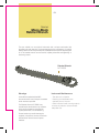
1
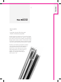
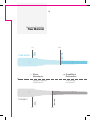
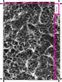
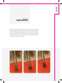
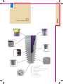
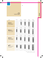
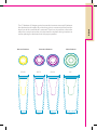
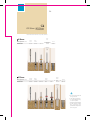
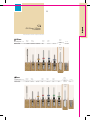
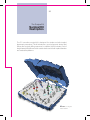
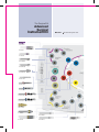
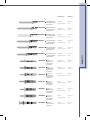
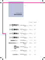
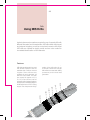
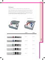
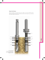
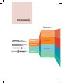
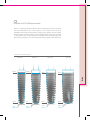
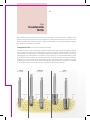
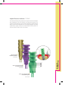
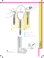
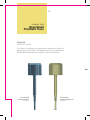
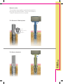
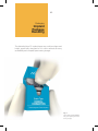
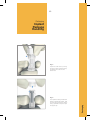
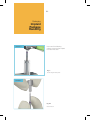
MIS C1 Guide | 2015 ® User Manual © MIS Corporation. All Rights Reserved. MIS reserves the right to modify the products described in this manual as well as to revise this publication at any time and without informing any person of such revision or change. All rights reserved. No part of this publication may be reproduced, transcribed, stored in an electronic retrieval system, translated to any language or computer language, or transmitted in any form whatsoever without the written consent of the publisher. Questions, comments or requests will be addressed promptly by contacting MIS specialists directly through our e-mailing address: [email protected]. The MIS website can be accessed at www.mis-implants. com. This online site highlights current products and reflects all new discoveries and developments. Note: This User Manual is for educational purposes only. The MIS Quality System complies with international quality standards: ISO 13485:2003 - Quality Management System for Medical Devices, ISO 9001: 2008 – Quality Management System and CE Directive for Medical Devices 93/42/EEC. MIS products are cleared for marketing in the USA and CE approved. Overview 8. Introduction 9. Raw Material 12. Manufacturing Process 13. Implant Surface Overview. 16. Histology 17. Hydrophilicity 6. Overview Introduction MIS is a dynamic, state-of-the-art production company, developing and manufacturing a comprehensive range of dental implants designed to provide long-lasting successful solutions to partial and complete edentulous conditions. MIS implant systems combine several advantageous elements such as choice of raw materials, macro-structure, micro-structure and surface treatments, in order to achieve high primary stability and successful osseointegration. MIS upholds high quality standards by conducting comprehensive quality assurance evaluations throughout the entire production process. The unique MIS implant surface treatment combines sand-blasting and acid-etching to increase surface area, creating both micro and nano-structures and eliminating surface contaminants. The implant surface is continuously monitored by a comprehensive series of tests, conducted both in-house and by internationally recognized research institutes. Tests include: - Mechanical tests - XPS analysis - Roughness analysis - Surface analysis - SEM evauations - Cytotoxicity tests - Sterility validations - Torque removal values - Histology Overview Raw Material - Biocompatible - Safe - Long-term proven clinical success - Superior mechanical properties All MIS implants are made from Ti-6Al-4V ELI (Grade 23), the higher purity version of Ti-6Al-4V. This specific type of alloy combines biocompatibility, excellent fatigue strength and low elastic modulus. These benefits make Ti-6Al-4V ELI mechanically superior to titanium grade 4 and the ultimate dental and medical titanium grade. Similar to commercially pure titanium (Grades 1-4), the outer surface of all MIS implants are comprised of a thin layer of pure titanium oxide (TiO2). In this way, bone cells cannot differentiate between the different titanium grades. The TiO2 layer also prevents metallic ions leaking from the alloy, for safe long-term use. Overview 7. 8. Mechanical Properties Raw Material 113 860 Ti-6Al-4V-ELI 1 2 Shock Absorbency Durability to Deformation Modulus of elasticity (1000X N/mm2) Yield strength, min (N/mm2) 1 2 Ti-Grade 4 103 480 Overview 9. Ti-6Al-4V-ELI = Ti-Grade 4 Ti-6Al-4V-ELI > Ti-Grade 4 Ti-6Al-4V-ELI > Ti-Grade 4 930 3 Durability to Fracture Tensile strength, min (N/mm2) 3 550 10. Overview Manufacturing Process Structure (Raw Material) MIS Surface Treatment Sand-Blasting Acid-Etching Roughness (Macro and Nano Structures) The combination of sand-blasting and acid-etching induces macro and nano-structures that significantly increase surface area of the implant body for optimal osseointegration. The roughened surface improves bone adhesion, as well as the proliferation and differentiation of osteoblasts. Overview 11. Overview Implant Surface Osseointegration is defined as the attachment of bone to dental implants, and is the critical factor related to the long-term success of dental implants. Osseointegration is determined by both the raw material of the implant, morphology and surface chemical composition. 2 μm 20 μm SEM image of two C1 implants SEM image of the implant surface Macro-structure Surface composition The geometric design of the body and thread profile of the implant act to increase primary stability and to distribute forces from the implant to the surrounding bone. The outer surface of MIS implants, consist of a thin layer of pure titanium oxide (TiO2). Acid-etching and packaging processes are performed in a controlled environment clean-room to ensure purity and quality. Implants are inspected by electron microscope (SEM) scan and X-ray photoelectron spectroscopy (XPS), to ensure implants are free of contaminants. Micro and nano-structure All MIS implants are sand-blasted and acidetched. This surface treatment increases the implant surface area, creating both micro and nano-structures, while eliminating various surface contaminants. MIS is one of only a handful of companies worldwide using electron microscopy on a daily basis for implant quality inspection. Sand-blasted and acid-etched surfaces have been substantially proven to maximize the BIC (Bone-to-Implant Contact), achieving immediate and long-lasting osseointegration. 50 μm SEM image of the implant surface showing the micro-structure 10 μm SEM image of the implant surface showing the nano-structure Overview 14. Overview Histology Histologic section of a C1 implant, 5 weeks after placement. Courtesy of Paulo G. Coelho, DDS, PhD, NYU College of Dentistry. Histologic section of a C1 implant, 5 weeks after placement. Courtesy of Paulo G. Coelho, DDS, PhD, NYU College of Dentistry Overview Hydrophilicity Current literature demonstrates a linkage between improved bone healing and early osseointegration with the hydrophilicity of surface. MIS implant surface treatment combines sand-blasting and acid-etching. This combination ensures surface purity and hydrophilic properties. The images demonstrate liquid "climbing" upwards on the implant surface. Overview 15. Implants 20. Introduction: C1 Implant 21. Fixture - Technical Info Implants. 23. Features 24. Implant Range 25. Procedure 18. Introduction MIS is proud to introduce C1, an addition to our implant selection. The C1 implants feature a unique combination of attributes that result in a new innovative implant that provides high initial stability and a state of the art conical connection which incorporates platform switching technology. A large variety of superstructures and components are available, providing solutions for every possible clinical scenario. All implants and components are color-coded, according to their restorative platform, with a golden anodized hue for best esthetic results. Implants 19. Fixture - Technical Info 1 8 7 2 6 3 5 4 1 Conical connection 2 Conical body 3 Surface - sand-blasted + acid-etched 4 Two spiral channels 5 Domed apex 6 Dual thread 7 Micro rings 8 Platform switching 20. External Design Platform switching Dual thread The C1 features platform switching, that keeps the implant-abutment connection away from the bone; minimizing bone resorption. Platformswitching additionally allows more vital growth of the soft tissue. ▪ The C1 features a dual thread design which increases the BIC (Bone to Implant Contact) over the entire body of the implant. The dual thread doubles implant insertion rate (1.50mm), facilitating a simpler and faster implant placement. Conical shape ▪ The thread profile is especially designed for a flawless, easy insertion and a high primary stability. ▪ ▪ The conical root shape of the C1 implant and a unique thread design ensure superior primary stability, making the C1 the implant of choice for a wide range of clinical cases and loading protocols. The root shape design makes the C1 an ideal implant when space is restricted due to adjacent teeth or implants. Two spiral channels and domed apex The C1 features a domed apex, providing a high tolerance and safe procedure during insertion. Two cutting blades at the implant apex establish the self-tapping properties of the C1; supporting a simpler, safer and faster procedure. ▪ The C1 is self taping with mild bone compression that enhances primary stability. Surface treatments C1 implants are sand-blasted and acidetched. These surface treatments increase the implant surface area by creating both micro and nano-structures and eliminating various surface contaminants. Micro-rings At the neck of the C1, micro-rings significantly increase the BIC (Bone to Implant Contact), avoiding bone resorption at the crestal zone. Implants 21. Implant Range Length 8mm 10mm 11.50mm 13mm 16mm C1-10330 C1-11330 C1-13330 C1-16330 C1-08375 C1-10375 C1-11375 C1-13375 C1-16375 C1-08420 C1-10420 C1-11420 C1-13420 C1-16420 C1-08500 C1-10500 C1-11500 C1-13500 C1-16500 Type 3.30mm Screw type implant Narrow platform 3.75mm Screw type implant Standard platform 4.20mm Screw type implant Standard platform 5mm Screw type implant Wide platform * Implant package includes: a cover screw, a temporary cylinder and a final drill. 22. Conical Connection Narrow Platform Standard Platform Ø 3.30 Ø 3.75 Ø 4.20 Ø 2.75 Ø 3.15 Ø 3.15 Ø 2.50 Ø 3.10 Ø 3.60 Wide Platform Ø5 Ø4 Ø 4.50 Implants The C1 features a 6-degree conical connection to ensure a secure fit between the abutment and implant. By minimizing micro-movement at that junction bone loss at the crestal level is reduced. There is a six-position cone index within the conical connection to help orient the implant during insertion as well as placing the abutment into the proper position. 24. Ø 3.30mm / Ø3.75mm Procedure Recommended insertion torque: 35-60 Ncm. Ø 3.30mm Drill Speed (RPM) 12001500 9001200 Diameter Ø1.90 Ø2.40 200400 Ø2.40 Ø3 Ø3.60 15-25 Ø3.30 Final drill For bone type 1,2&3 Ø 3.75mm Drill Speed (RPM) Diameter 12001500 9001200 Ø1.90 Ø2.40 200400 500700 Ø2.40 Ø3 Ø3 Ø3 Ø3.60 15-25 Ø3.75 Final drill For bone type 1,2&3 Do not use the final drill for type 4 bone. The drilling sequence is demonstrated using a 13mm implant. Procedure recommended by MIS cannot replace the judgment and professional experience of the surgeon. 25. Implants Ø 4.20mm / Ø5mm Procedure Recommended insertion torque: 35-60 Ncm. Ø 4.20mm Drill Speed (RPM) 12001500 9001200 Diameter Ø1.90 Ø2.40 Ø2.40 500700 400700 Ø3 Ø3.50 200400 Ø3.50 Ø3.50 Ø4 15-25 Ø4.20 Final drill For bone type 1,2&3 Ø 5mm 1200- Drill Speed (RPM) 1500 Ø1.90 Diameter 9001200 Ø2.40 Ø2.40 500700 400700 400600 Ø3 Ø3.50 Ø4 200400 Ø4 Ø4.10 Ø4.90 Final drill For bone type 1,2&3 15-25 Ø5 Surgical Pro. Surgical Procedures. For MIS Implants 28. Indications & Contraindications 30. Step-by-Step Protocol 28. Surgical Procedures Indications & Contraindications These include, but are not limited to: Indications Adequate bone is needed to support the implant with width and height being the primary dimensions of concern. The amount of available bone should be evaluated based on accepted imaging and radiological techniques used in implant dentistry. ▪ Metabolic bone diseases. ▪ Blood and clotting disorders. ▪ Medications affecting clotting or bone turnover. ▪ Significant vascular or anatomic factors at the implant site. ▪ Treatments, medications, or disorders that interfere with bone biology or wound healing. ▪ Hypersensitivity or known allergy to any components of the implants or their superstructures. In addition, a very careful evaluation must be made as to the location of vital blood vessels, nerves, maxillary sinus, soft tissue spaces, and their relation to the site planned for implant placement. Other Contraindications ▪ Poor patient motivation. ▪ Psychiatric disorders that interfere with patient understanding and compliance with the necessary procedure. Contraindications All contraindications associated with elective surgery should be considered. ▪ Unrealistic patient expectations. ▪ Unattainable prosthodontic reconstruction. ▪ Inability of patient to manage oral hygiene. Risks Risks associated with the surgical procedure fall into four broad categories: 1. Immediate anesthetic and surgical risks. 3. Medical threats to long-term retention. 4. Long-term deleterious effects of implants on health. The risks may include: Inadvertent perforation of the nasal maxillary sinus, local and systemic infections, perforation into soft tissue spaces, rupture of primary blood vessels and nerve injury. Temporary conditions that might result from implant placement may include pain and swelling, speech difficulties and haemorrhage. Long-term complications may include (but are not limited to) nerve injuries and persistent local or systemic infections. Special care and attention needs to be given to susceptible individuals with compromised immune systems due to medications, systemic conditions or those who underwent body-part replacements. Important Warning Practitioner's lack of adaquate training, knowledge and experience are considered major risk factors to the patient's health and to implant success. Therefore, no implant placement procedure should be performed without prior training by a certified institution. Surgical Pro. 2. Psychological and psychiatric risks. 30. Surgical Procedures Step-by-Step Protocol The surgical manual is designed to provide an overview of the pre-surgical and the surgical procedures applicable to the C1 implant range. Successful implant placement procedures are the result of a wide range of factors. This step-by-step protocol aims to ensure that significant factors are not overlooked. Step 1. Patient Selection and Medical History (General medical history) Patients must be carefully assessed for their ability to safely undergo surgical procedures. Medical history should be evaluated to ensure that patients are not put at risk. Certain medical conditions are considered either absolute or relative contraindications for surgery. These may relate (but not be limited) to the following conditions: Patients who are either taking or have taken medications for the treatment of osteoporosis; immunodeficiency or immunosuppressive treatments; malignancies; head and neck radiation; poorly controlled diabetes or other hormonal disorders; bleeding disorders or anticoagulant therapy; recent myocardial infarction, severe cardiac insufficiency and valve pathology; general bone diseases; hypersensitivity or known allergy to specific relevant materials; psychiatric or personality disorders that limit or interfere with patients' understanding and compliance. Please be aware of the fact that updates based on current medical literature may include or exclude certain conditions. surgeon to ensure that all required documentation is available and recorded before and after surgery. Vertical and horizontal dimensions of implant sites should be measured and charted. The anatomical relationships of neighboring teeth and proximity to anatomical structures such as the mandibular canal, maxillary sinus and base of the nose must be evaluated. Bone inclination and shape should also be taken into account. Surgical guides with radiopaque markers are recommended. These, coupled with computerized tomographic radiographs can later be altered to be used as computer based surgical guides. Step 2. Dental Conditions and Oral Hygiene Step 3. Radiographs and Imaging Diagnosis and treatment planning for implant placement require the use of different types of radiographs and imaging technologies. Panoramic radiographs are considered standard pre-surgery radiographs, however additional imaging modalities such as CT (Computerized Tomography), tomography and periapical radiographs may be required. It should be emphasized that certain countries require specific radiographs to be taken before, during and after surgery. It is the obligation of the Surgical Pro. A complete and thorough intraoral examination must be performed and recorded. This must include an evaluation of the dentition, oral hygiene, smoking, habits, attitude to oral health, and any other relevant information. Implant procedures should not be performed on patients with active osteolitic conditions, active periodontal disease or infectious areas at the implant site. Extreme bruxing and clenching should be taken into consideration. Step 4. Treatment Plan (Patient cooperation) Based on patients' needs, alternative treatment plans should be considered and discussed. The chosen treatment plan should result in a sequence of actions related to initial preparations, surgical phase and a restorative phase. 32. Surgical Procedures Step-by-Step Protocol Step 5B. Surgical Phase Step 5A. Implant Selection C1 implants feature a range of diameters and lengths. It is recommended that Wide platform implants are used in the premolar and molar areas, while Standard platform implants are used in the anterior areas. Specific analysis of available bone and distance from vital structures at each proposed site may lead to the choice of specific implant length and diameter; however, current augmentation procedures may allow the use of longer or wider implants. Surgery should be performed under strict infection control conditions. Preoperative medications and/or antibiotics may be required based on the patient's condition and the extent of surgery, and should be decided upon by the operating surgeon. Other monitoring measures, including blood-pressure and pulse measurements should also be considered. Emergency resuscitation apparatus should be available. Warnings: C1 implants are supplied in a sealed and sterilized package. Implants should never be reused, and implants whose sterility is compromised should not be used. Implants should not be used later than the specific expiration date printed on the package. Implant placement should be performed in accordance with acceptable placement and loading protocols. MIS recommended procedures are described on pages 20-43. However, it should be emphasized, that procedures recommended by MIS cannot replace the judgment and professional experience of the surgeon. The sale of MIS implants is restricted by law to licensed dentists only. Implant placement procedures should only be performed by trained and licensed dentists. Initial planning is of the utmost importance. As this is a prosthetic driven procedure. It is advisable that restorative dentists are involved at the planning and surgical phases as active participants when making decisions affecting the choice of implant type and the 3-dimensional positioning of the implants. Step 7. Restorative Phase C1 implants can support different types of final restorations. Following the solution specified in the treatment plan, the final restoration is fabricated based on accepted restorative protocols. Special attention should be given to ensure correct occlusal adjustment, in order to prevent overloading the implant. MIS superstructures and components must be used with all MIS implants. Surgical Pro. 12 24 Step 6. Osseointegration Phase Current literature supports multiple loading options. The dentist should decide when to load implants based on specific parameters, related to their individual case. Step 8. Follow-up Periodic follow-up evaluations including radiographs are recommended. Special attention should be put on oral hygiene and habits, occlusion adjustments and the stability of the prosthesis. Surgical Kit Surgical Kits. 36. Surgical Kit Description 38. Advanced Surgical Instrument Kit 40. Kit Contents 36. The Surgical Kit Surgical Kit Description The C1 innovative surgical kit is designed for simple and safe implant placement procedures. The kit introduces a novel ergonomic design that follows the surgical drilling sequence. In addition, the kit includes a set of length-based pilot drills and color-coded visual cues of both implant diameter and restorative platforms. MK-0044, C1 Surgical Instruments Kit Please Note: The surgical kit is made of medically approved materials. The surgical kit can be fully sterilized using an autoclave at 134°C (273°F) for 6 minutes. Do not exceed 134°C. The surgical kit is compact and easy to store. Tray can be removed from the box for easy cleaning and sterilization. indicated for these materials. To avoid damage, please refrain from using: Cleaning and disinfection agents containing high rates of chlorine ■ Cleaning or disinfection agents containing oxalic acid. ■ In order to prevent damage to instruments that are color-coded, please refrain from using: Detergents and cleaning agents containing high rates of the aforementioned chemicals. ■ Extremely high temperature during cleaning and sterilization. ■ Steam flow is optimized through built-in vents. Conduct a visual inspection of the instruments prior to each use. Do not use faulty or dull instruments. Clean and disinfect each instrument separately ■ Do not allow traces/residue (blood, secretion, tissue residue) to dry on the instruments. Always soak in disinfecting fluid immediately after use ■ Use only stainless steel dedicated detergents and strictly follow usage instructions ■ Rinse instruments thoroughly with water to remove any remaining disinfectants or cleaning agents ■ Do not store instruments that are damp or wet ■ Use only nylon bristle brushes to clean instruments. Clean the cavities and hollow spaces thoroughly ■ The use of an ultrasonic bath is highly recommended ■ Do not clean/disinfect instruments made of different materials together ■ To prevent damage, do not allow sharp instruments to touch other instruments during cleaning. ■ After mechanical or manual cleaning, all surgical appliances must be sterilized in an autoclave, at 134°C (273°F) for a duration of 6 minutes. Do not exceed 134°C. Never use dry sterilizers ■ Inspect for corrosion after sterilization. ■ Warning Avoid damage! Temperatures higher than 150ºC may cause damage. Radel, steel and silicone components may support repeated exposures to temperatures up to 180ºC, but the lifetime of the trays may be shortened. The use of inappropriate chemical agents may cause damage to the trays and to the instruments. Please handle them with care to avoid breakage. Never use broken trays or instruments. Do not open the box while still hot after sterilization. Cleaning Procedure Stainless steel instruments should be cleaned and sterilized with materials that are specifically Surgical Kit Please Note: The Surgical Kit Advanced Surgical Instrument Kit MK-0044 With external irrigation drills CS-PF375 CT-SLI10 CT-SSI10 MT-CSN33 MT-GDN33 MT-GDN50 MT-BTT24 MT-BTT30 MT-BTT35 MT-TDT30 MT-TDT35 CN-PF330 CT-NSI10 CT-NLI10 MT-P2408 MT-P2410 MT-SMD10 MT-BTT40 MT-BTT45 MT-BTT50 CW-PF500 CT-WSI10 CT-WLI10 MT-RI030 MT-TDT45 MT-TDT50 MT-PP240 MT-DE001 MT-SM005 MT-LM005 MT-P2411 MT-P2413 MT-TDN19 MT-P2416 MT-SRA10 Surgical Kit MT-TDT40 40. The Surgical Kit Kit Contents The C1 Surgical Kit includes tools that are designed especially for the step-by-step implant placement process. Correct preparation of the implant site ensures efficient and accurate installation and high primary stability. Surgical Kit 42. The Surgical Kit Kit Contents Dimensions Material 6 MT-P2406 Pilot drill with built in stopper Ø2.40 height 6mm Ø2.40mm Length 31.8mm Stainless steel MT-P2408 Pilot drill with built in stopper Ø2.40 height 8mm Ø2.40mm Length 31.8mm Stainless steel MT-P2410 Pilot drill with built in stopper Ø2.40 height 10mm Ø2.40mm Length 31.8mm Stainless steel MT-P2411 Pilot drill with built in stopper Ø2.40 height 11.5mm Ø2.40mm Length 31.8mm Stainless steel MT-P2413 Pilot drill with built in stopper Ø2.40 height 13mm Ø2.40mm Length 31.8mm Stainless steel MT-P2416 Pilot drill with built in stopper Ø2.40 height 16mm Ø2.40mm Length 31.8mm Stainless steel MT-BTT24 Body try-in Ø2.40mm for tapered impl. procedure Ø2.40mm Length 28.5mm Stainless steel MT-BTT28 Body try-in Ø2.80mm for tapered impl. procedure Ø2.80mm Length 28.5mm Stainless steel MT-BTT32 Body try-in Ø3.20mm for tapered impl. procedure Ø3.20mm Length 28.5mm Stainless steel MT-BTT40 Body try-in Ø4mm for tapered impl. procedure Ø4mm Length 28.5mm Stainless steel MT-BTT45 Body try-in Ø4.50mm for tapered impl. procedure Ø 4.50mm Length 28.5mm Stainless steel MT-BTT50 Body try-in Ø5mm for tapered impl. procedure Ø 5mm Length 25.5mm Stainless steel MT-TDN30 Twist drill 3mm external irrigation Ø 3mm Length 37.6mm Stainless steel 8 10 11.5 16 MT-P2416 Surgical Kit 13 44. The Surgical Kit Kit Contents Dimensions Material MT-TDT32 Twist drill 3.20mm external irrigation Ø3.20mm Length 37.5mm Stainless steel MT-TDT40 Twist drill 4mm external irrigation Ø4mm Length 38.2mm Stainless steel MT-TDT45 Twist drill 4.50mm external irrigation Ø4.50mm Length 38.2mm Stainless steel MT-TDT50 Twist drill 5mm external irrigation Ø5mm Length 38.2mm Stainless steel Length 27.5mm Stainless steel MT-SMD10 Spade marking drill MT-TDN19 Marking drill Ø1.90mm external irrigation Ø1.90mm Length 34mm Stainless steel MT-SRA10 Square connection to ratchet adapter Length 15.5mm Stainless steel MT-LM005 Long motor adapter for 0.05" hex. Length 29mm Stainless steel MT-SM005 Short motor adapter for 0.05" hex. Length 24mm Stainless steel Material MT-DE001 Drill extender Length 28.85mm Stainless steel MT-PP240 Parallel pin Ø2.40mm for tapered impl. procedure Ø2.40/ Ø3mm Titanium CN-PF330 Direct press fit for closed tray coni. con., NP Length 16mm Stainless steel CS-PF375 Coni. con. direct press fit for closed tray, SP Length 16.6mm Stainless steel CW-PF500 Coni. con. direct press fit for closed tray, WP Length 16.6mm Stainless steel CT-NSI10 Coni. con. short insertion tool, NP Length 22mm Stainless steel CT-NLI10 Coni. con. long insertion tool, NP Length 30mm Stainless steel CT-SSI10 Coni. con. short insertion tool, SP Length 22mm Stainless steel CT-SLI10 Coni. con. long insertion tool, SP Length 30mm Stainless steel CT-WSI10 Coni. con. short insertion tool, WP Length 22mm Stainless steel CT-WLI10 Coni. con. long insertion tool, WP Length 30mm Stainless steel MT-CSN33 Countersink for Narrow platform implant system Ø3.30mm Length 26mm Stainless steel MT-GDN33 Countersink for Standard platform implant system Ø3.75mm/ Ø4.20mm Length 26mm Stainless steel MT-GDN50 Countersink for Wide platform implant system Ø5mm/Ø6mm Length 26.8mm Stainless steel Surgical Kit Dimensions Using MIS Drills Color Code Drilling Depth Drill Indications Final Drill Drilling Into Hard Bone Drill Cutting Capability Ceramic Drills Drill Maintenance Drills Drills. 48. 50. 52. 54. 56. 58. 59. 60. 61. 48. Drills Using MIS Drills Implant placement procedures require the use of several drills with different diameters and characteristics. MIS offers drills with internal and external irrigation, as well as conical and ceramic drills. Most MIS drills are marked for depth control and are color-coded for immediate identification of drill diameter. Features quality of the drills allow for up to 30 uses. Careful use of sharp drills will ensure atraumatic drilling procedures, and minimal heat generation. 6mm 8mm 16mm 13mm 11.5mm 10mm MIS drills are designed to be used with all MIS implants. Drills are available with or without internal irrigation. Short drills are also available for each diameter. All drills are color-coded. The drills are marked for depths of 6, 8, 10, 11.5, 13 and 16mm, and are equipped with a ledge that allows the connection of MIS drill stoppers. All MIS drills have a 120ºC cutting degree. The sharpness and high Drill Stoppers MIS offers drill stoppers to enable simple and accurate depth control. The C1 Drill Stopper Kits (MK-CDS08, MK-CDS10, MK-CDS11, MK-CDS13) are a series of kits, each used for one specific implant length: 8, 10, 11.5 or 13mm. For commonly used 3.75 or 4.2 implants, MIS offers a single assorted kit - the C1 Drill Stoppers Kit Standard Platform (MK-BC101), which includes all stoppers required for safe placement of Standard platform implants. C1 Drill Stoppers Kit C1 Drill Stoppers Kit Standard Platform (MK-BC101) Implant Length Ø 3mm 37.6mm Ø 3.50mm 37.7mm Ø 4mm 38.2mm Ø 4.50mm 38.2mm Ø 5mm 38.2mm Drills 8mm 50. Drills Ø3. 50 Ø4 Ø4.50 Ø5 Color Code Ø3 Color-coding is used for easy identification of drills or implants diameters as follows: Yellow Implant Ø 3.30 Drill Ø 2.40 Red Implant Ø 3.75 Drill Ø 3 Blue Implant Ø 4.20 Drill Ø 3.50 Green Drills Implant Ø 5 Drill Ø 4 White Implant Ø6 Drill Ø 4.50/5 52. Drills Drilling Depth Important! Please note that the apical tip of all MIS twist drills is up to 0.5mm longer than the depth of the corresponding implant. This should be taken into account during the planning phase. Geometrical difference between the drill tip and the implant Depth Verification Depth verification can be done by the use of Body Try-In tools (MT-BTTx). Laser markings correspond to those on the drills and allow a safe, easy way to ensure that the required depth was achieved. 16mm 11.5mm 13mm 11.5mm 10mm 10mm 8mm 8mm 6mm 6mm For demonstration purposes, the (MT-P2413A) drill, 13mm height with builtin stopper, is shown. Drills 13mm 54. Drills Drill Indications Recommended Speed 1200-1500 RPM Spade Drill 1200-1500 RPM Marking Drill Pilot Drill 500-1000 RPM Twist Drill 400-600 RPM The Spade Drill has a diameter of Ø1.9mm and a sharp tip. The Spade Drill is 27.5mm in length and made of stainless steel. The Marking Drill supplied is 34mm in length and 1.90mm in diameter. Aim of Use The Spade Drill is used to mark a reference point for further drills. It is especially useful in immediate placement procedures. The Marking Drill is used for creating a reference point in the center of the ridge, and to mark the location for further drilling. C1 Pilot Drills come in five different lengths: 8, 10, 11.5, 13 and 16mm and are equipped with a stopper to simplify the drilling procedure. Pilot Drills are the first invasive drills used for the preparation of a fixture site. The Pilot Drills are length specific to ensure precise drilling depth. Twist Drills come in a variety of diameters and lengths. Twist Drills are used to widen the osteotomy. They are NOT length specific, and have laser markings for 6, 8, 10, 11.5, 13 and 16mm implants. The use of stoppers is highly recommended when using Twist Drills. Drills Length & Diameter 56. Final Drill Final Drill for implant diameters Ø3.30 Ø3.75 Ø 3.20 Ø 2.4 Ø4.20 Ø 3.60 Ø3 Ø5 Ø 4.90 Ø4 Ø 3.50 Ø 4.10 Implant and Drill Measurements Each C1 implant package contains a sterile, single-use Final Drill. The drills are recommended for use in bone types 1, 2 & 3. Each Final Drill has a predetermined length and diameter, matching the relevant implant shape and dimension ensuring maximum initial stability while preventing pressure on the implant neck. The length-specific final drills also promote a short and safe drilling procedure. The recommended drilling speed is 200-400 Rpm. Implant and drill measurements Ø 3.30mm Ø 4.20mm Ø 3.75mm Ø 5mm Ø3.60 Ø4.10 Ø4.90 Ø2.40 Ø3 Ø3.50 Ø4.10 Gap 0.15mm Gap 0.2mm Gap 0.3mm Gap 0.4mm Drills Ø3.20 58. Drills Countersink Drills When drilling into hard bone, extra care should be exercised to prevent overheating. Therefore, lower speeds and higher torque should be used. In addition, to prevent extensive pressure on the bone or the need of extremely high insertion torque, it is highly recommended to use the appropriate countersink drills at the end of the drilling procedure. Countersink Drills (MT-CSN33, MT-GDN33, MT-GDN50) Countersink Drills are used to enlarge the crestal area of the implant site, preventing excessive pressure on the implant neck. Depth marks of 3.30 appear on the Narrow platform Countersink Drill (MT-CSN33), 3.75 and 4.20mm marks appear on the Standard platform Countersink Drill (MT-GDN33), 5 and 6mm marks appear on the Wide platform Countersink Drill (MT-GDN50). The recommended drilling speed is 200-500 RPM. When drilling into hard bone, extra care should be exercised to prevent overheating. Therefore, it is recommended to use lower drilling speeds with higher torque. In addition, to prevent excessive pressure on the bone or the need for extremely high insertion torque, it is strongly recommended to use the appropriate countersink drills upon completion of the drilling procedure. Narrow MT-CSN33 3.30mm Wide MT-GDN50 Standard MT-GDN33 3.75mm 4.20mm 5mm 6mm 59. Drills Ceramic Drills Ceramic Drills feature reduced vibration, smooth operation and continuous substance removal. MIS Ceramic Drills are made from a high performance mixture of zirconium dioxide (zirconia) and aluminum oxide (alumina) ceramics. The mixture of these two materials provides an above-average bending strength of 2,000 MPa. In comparison, the bending strength of zirconium oxide ceramic, used in the manufacturing of root posts is 1,200 Mpa. Drills Advantages: Metal-free, biocompatible, corrosion-free MT-CRD21 Marking Drill MT-CRD20 Pilot Drill MT-CRD28 Twist Drill Dimensions: Ø2.10mm Length 28.5mm Ø2mm Length 33.5mm Ø2.80mm Length 35mm Material: Zirconiaalumina ceramic Zirconiaalumina ceramic Zirconiaalumina ceramic 60. Drills Drills Maintenance Correct and careful maintenance of MIS drills is extremely important. Damage to drill tips can cause significant impairment of drill function. The following are detailed instructions for proper maintenance. Instructions for Maintenance of Drills Prior to First Use Instructions for Cleaning and Storage of Drills After Use Stage 1: Cleaning and Rinsing - Drills should be dipped in appropriate detergent, rinsed, and dried. The use of an ultasonic bath is highly recommended. Stage 2: Sterilization - Drills should be sterilized in an autoclave at 134°C (273°F) for 6 minutes. Do not exceed 134°C. Stage 3: During Use - Drills should be soaked in a sterile saline solution until the cleaning stage. Stage 1: Cleaning - Drills should be brushed with detergent to remove any remaining blood or tissue. Stage 2: Ultrasonic cleaning - Drills should be cleaned in an ultrasonic bath with appropriate detergent. Note: during ultrasonic cleaning, contact between drills should be avoided. Stage 3: Rinsing - Drills should be rinsed under running water and dried. Stage 4: Sterilization - Drills should be sterilized in an autoclave at 134°C (273°F) for 6 minutes. Do not exceed 134°C. Stage 5: Storage/Use - Store kits in a cool and controlled environment. Please note that sterilization may expire after a certain time. If kits have been stored for a prolonged period, resterilize them prior to use. 61. Drills Drills Maintenance Recommendations Drills - Cutting tools should be used for a maximum of 30 uses. - Distilled water should be used in order to avoid surface stains. - 134°C (273°F) for 6 minutes: Autoclave for Instruments/drills/kits 134 6 Minutes Autoclave serialization cycles 64. Specialized Surgical Tools 72. Specialized Prosthetic Tools 76. Screw Tests 77. Maintenance Surgical & Prosthetic Tools Surgical & Prosthetic Tools. 64. Ratchet Mono-Block Ratchet Wrench The new ratchet is a mono-block instrument with a unique mechanism that simplifies use and cleaning. To prevent damage to the mechanism, it is critical that the ratchet is used only with keys and adapters that are specifically designed for it. The ratchet wrench can be used for implant placement and tightening or loosening screws. Ratchet Wrench MT-RI030 Warnings Instrument Maintenance It should be emphasised that MIS recommends the use of a torque controlled driver whenever possible. - The device is not sterile. The Ratchet Wrench MT-RI030 may transfer torque levels that do not correlate to the recommendations specified for implant placement or screw fastening. Excess loads may result in damage to implants, components, screws, the wrench itself and even to the bone-to-implant interface. - Cleaning and sterilization are required prior to first use. - Clean instrument with running water to remove any blood or tissue immediately after use. Cleaning and Disinfection: Sterilization - Immerse instrument in an approved cleaning/disinfecting solution. - All dental instruments must be sterilized prior to each use. - Use of an ultrasonic cleaner is highly recommended. - The device is delivered non-sterile. - DO NOT USE agents containing high cocentration of chlorine or agents containing oxalic acid. - Before use, the device must be sterilized by autoclave at 134°C (273°F) for 6 minutes. Do not exceed 134°C. - Use distilled water to prevent water stains. Surgical & Prosthetic Tools User Instructions Store the ratchet on its own, not attached to any tools. Clean thoroughly immediately after use. 66. Surgical Tools Specialized Surgical Tools Implant Site Depth Probe MT-BTI10 Ø 1.8 16 6 13 11.5 10 8 Implant size-based ruler Ø 2.7 mm Features The Depth Probe enables quick and easy measurements and examination of a prepared implant site, at each step of the procedure. Marked depths: 6, 8, 10, 11.5, 13 and 16mm. The Depth Probe includes an apical flat section to ensure accurate placement within the ossteotomy. Dimensions: Ø 1.80/Ø 2.70mm. Total length:100mm. mm Implant Direction Indicator CT-SDI01 Connected directly to the implant, this surgical instrument enables the visualization of the 3D position of a particular implant. The implant indicator features groove marks indicating gingival heights (each groove mark indicates 1mm of gingival height). The round cavities at the upper section of the tool represent the position of the anti-rotational index within the implant. 1mm 1mm Coni. con. direct press fit for closed tray, SP 1mm CS-PF375 Coni. con. direct press fit for closed tray, WP CW-PF500 Surgical & Prosthetic Tools Narrow Implant Direction Indicator CN-PF330 68. Surgical Tools Specialized Surgical Tools C1 Insertion Tools C1 implants are divided into Narrow platform implants (3.30mm), Standard platform implants (3.75 and 4.20mm), and Wide platform implants (5mm). Long and short insertion tools are available for each of the C1 platforms. In order to simplify procedures, the 3-in-1 concept was developed. This concept is based on the ability of one insertion tool to be used either directly in a motor, with a manual wrench or with any of the MIS ratchets. Connection to motor Connection to motor Connection to motor Connection to ratchet Implant index position Index adapter 2.75mm 3.15mm 3.15mm 4.20mm 2 3 2 1 3 1 Insersion tool for use manually 2 Insertion tool for motor Surgical & Prosthetic Tools 3 Insertion tool for use with Ratchet wrench The same procedure is applicable for Wide platform tools. 70. Prosthetic Tools Specialized Prosthetic Tools Friction Fit MT-RE172/ MT-RE160 The friction fit extractors are designed to separate the friction fit abutments from the implant. The extractors are color-coded, Blue for Standard/Wide abutments and Yellow for Narrow abutments. Int. connection abutment extractor MT-RE172 Int. connection abutment extractor, NP MT-RE160 Mode of action The extractor key applies vertical load parallel to the long axis of the implant. Thus it can release a "locked" abutment from an implant. For Standard / Wide Implants ▲ Platform switching ▲ ▲ Friction fit Surgical & Prosthetic Tools For Narrow Implants 72. Prosthetic Tools SOS Broken Screw Kit SOS Broken Screw Kit MT-TF172 / MT-RT001/ MT-HW001 The SOS Broken Screw Kit was designed to facilitate the removal of a broken screw from within an implant. SOS Broken Screw Kit MK-0041 SOS Tools Thread Former MT-TF172 Hand Wrench MT-HW001 Retriever MT-RT001 1. 2. 3. A. Connect the retriever to a micromotor. B. Adjust the micromotor to low speed (15-25 RPM), max. torque and in reverse mode. A. Apply mild pressure with the retriever at the top of the broken screw. B. While maintaining pressure, activate the motor. This action should release the screw. If the screw is still not released, apply intermittent pressure on the screw. If internal threads are damaged: A. Use the thread former with care. B. Be sure to align the thread former parallel to the long axis of the implant. C. Always start by using a hand wrench. Apply gentle but firm force while turning the thread former in a clockwise direction. Release the pressure at the end of each complete turn by turning it 30' in a reverse direction, and repeat the action as needed. D. In instances where greater torque is needed, a ratchet may be used. Surgical & Prosthetic Tools Instructions for use: 74. Prosthetic tools Screw Tests Tensile test of dental screws 1800 Ti screw 2mm Gold screw 2mm 1600 1400 Load (N) 1200 1000 800 600 400 200 0 0.2 0.4 0.6 0.8 1 1.2 1.4 1.6 Displacement (mm) Fatigue test of dental screws 1600 Ti screw 2mm 1400 Max. force (N) 1200 1000 Test conditions: 800 20 Ti-6Al-4V ELI, M2 type screws. Loading frequency: 30Hz 600 400 Test results indicate that the fatigue limit of the tested screws is 530N and that the screws will not break even after 5 million cycles. 200 0 1.E+03 1.E+04 1.E+05 1.E+06 5.E+06 1.E+07 Number of cycles 75. Maintenance The wide variety of MIS surgical tools requires careful maintenance: Instrument maintenance: Disinfection Examination - Perform a visual inspection. - Dispose of damaged instruments. - Immerse instruments immediately after use. - Use approved agents only. - Observe manufacturer's recommendations regarding concentration/time/material compatibility. - Verify that detergents and cleaning agents do not contain oxalic acid or high rates of chlorine. - Avoid extremely high temperatures during cleaning and sterilization of the product. Check for: Broken or dull drill blades Bent instruments Corrosion Cleaning Storage - Remove all residues. - Use an ultrasonic bath. - Use anticorrosive cleaning agent. - Thoroughly rinse away cleaning and disinfecting agents with running water. - Use distilled water to prevent water spots. Store in a dry, dust-proof area. Keep instruments separated from chemicals. Resterilize prior to use, if instruments have been stored for a prolonged period of time. Drying Allow instruments to dry prior to sterilization. Sterilization Surgical instruments must be sterilized before use by autoclave, at 134°C (273°F) for 6 minutes. Do not exceed 134°C. Surgical & Prosthetic Tools MIS surgical instruments are delivered nonsterile, unless indicated otherwise. 80. Implant Package 82. Implant Identification Codes 83. Implant Data Label 84. Implant Package Handling Packaging Packaging. 78. Packaging Implant Package The innovative MIS packaging system is designed for simple and easy use. All of our implant boxes feature distinctive colors, large typeface, clear data labels and a pull tab for quick opening. Boxes are a uniform shape and height, specifically designed to fit in clinic cabinets for easy accessibility and compact space-saving storage. The Individual Implant Package Each C1 package contains: Instruction For Use, an implant, a single-use final drill, a cover screw and a PEEK temporary cylinder. We recommend instructions be read carefully prior to use. Implant package 10 Implant Package A convenient 10-implant package is available. The drawer-like box is ideal for storage in drawers or cabinets for easy identification of implant type, diameter and length. Insertion of the adapter To ensure that implants are sterile, and to prevent surface contamination, each implant is stored in a Titanium sleeve within an internal plastic tube. This tube is held in a larger sealed outer tube, marked with all relevant information. The inner tube is therefore sterile, and can be brought into the sterile surgical field whenever needed. Cover screw Implant Packaging Double Container System 80. Packaging Implant Identification Codes Identification markings on the outer tube cap enable quick identification of implant diameter (top), implant length (center) and implant platform size (bottom). Implant diameter Implant length (mm) Implant platform 81. Packaging Implant Data Label Each package contains three data labels, which includes all required information pertaining to the implant. The following image illustrates the label: Catalog No. 3.75x11.50 ® Type of implant & connection C1-11375 Implant diameter & length C1. conical connection implant dia. 3.75 L 11.50mm 123456 Date of manufacture 2010-12 0483 CE Mark Use-by date Packaging Lot No. 2005-12 82. Packaging Implant Package Handling The distinctive blue C1 implant boxes are a uniform shape and height, specifically designed to fit in clinic cabinets for easy accessibility and compact space-saving storage. Fig. 1 The convenient pull tab facilitates easy, quick opening of the box during surgery. 83. Packaging Implant Package Handling Fig. 2 Open the outer tube by turning the cap counter-clockwise. Drop the sterile inner tube into the sterile field. Packaging Fig. 3 The implant is held by the titanium sleeve. To expose the implant - hold the tube with the titanium sleeve facing up. Rotate and pull to open the upper cap. 84. Packaging Implant Package Handling OPTION 1 Use one of the following options to remove the implant from the inner tube: Fig. 4 Contra-angle hand piece OPTION 2 Fig. 4B Hand wrench 85. Packaging Implant Package Handling Fig. 5 Ratchet Implant placement (illustrated using a manual wrench) Packaging Fig. 6 86. Packaging Implant Package Handling Fig. 4 Implantation procedure Fig. 8 Open the bottom of the inner tube. Remove the cover screw using the MT-LM005 key 87. Packaging Implant Package Handling Fig. 9 Attach the cover screw to the implant using the MT-LM005 key The data labels should be attached to the medical chart Packaging Fig. 9 Cover Screw Temporary Cylinder Implant 88. Implant Package Handling Packaging Packaging Outer Tube Inner Tube Final Drill 90. Planning Transparency MIS offers a planning transparency, illustrating the full C1 implant range. It includes two sets of images: one actual size, and the other at a magnification of 125%, relevant for use with panoramic radiographs that include a similar inherent magnification. In addition, the transparency includes a 1:1 ruler. By placing the appropriate section of the transparency on a radiograph, a clinician can choose the best fitting implant diameter and length, as part of the planning process. The transparency available for C1 implants is: Cat No. MC-CONC1 91. Symbols Key to symbols on labels and instruction leaflets: Batch code Manufacturer Catalog number Do not resterilize For single use only Do not use if package is damaged Attention, see instructions for use Date of manufacture Sterilized using gamma irradiation EC REP Authorised representative in the European community Use-by date All rights reserved. No part of this publication may be reproduced, transcribed, stored in an electronic retrieval system, translated into any language or computer language, or be transmitted in any form whatsoever, without the prior written consent of the publisher. Warning: Only a licensed dentist should use these products. MP-UMCSE Rev.2 Apr 2015 ® MIS Implants Technologies Ltd. www.mis-implants.com MIS Quality System complies with international quality standards: ISO 13485:2003 - Quality Management System for Medical Devices, ISO 9001: 2008 – Quality Management System and CE Directive for Medical Devices 93/42/EEC. MIS products are cleared for marketing in the USA and CE approved.