1
Reference Manual
GUI Graphical User Interface
Rail Switch Power Lite (RSPL)
RM GUI RSPL
Release 2.0 02/2013
Technical Support
https://hirschmann-support.belden.eu.com
The naming of copyrighted trademarks in this manual, even when not specially indicated, should
not be taken to mean that these names may be considered as free in the sense of the trademark
and tradename protection law and hence that they may be freely used by anyone.
© 2013 Hirschmann Automation and Control GmbH
Manuals and software are protected by copyright. All rights reserved. The copying, reproduction,
translation, conversion into any electronic medium or machine scannable form is not permitted,
either in whole or in part. An exception is the preparation of a backup copy of the software for
your own use. For devices with embedded software, the end-user license agreement on the
enclosed CD/DVD applies.
The performance features described here are binding only if they have been expressly agreed
when the contract was made. This document was produced by Hirschmann Automation and
Control GmbH according to the best of the company's knowledge. Hirschmann reserves the right
to change the contents of this document without prior notice. Hirschmann can give no guarantee
in respect of the correctness or accuracy of the information in this document.
Hirschmann can accept no responsibility for damages, resulting from the use of the network
components or the associated operating software. In addition, we refer to the conditions of use
specified in the license contract.
You can get the latest version of this manual on the Internet at the Hirschmann product site
(www.hirschmann.com).
Printed in Germany
Hirschmann Automation and Control GmbH
Stuttgarter Str. 45-51
72654 Neckartenzlingen
Germany
Tel.: +49 1805 141538
Rel. 2.0 - 02/2013 – 11.02.2013
Contents
Contents
About this Manual
7
Key
9
Graphical User Interface
11
1
Basic Settings
19
1.1
System
20
1.2
Network
1.2.1 Global
1.2.2 ARP Table
1.2.3 IP Address Conflict Detection
25
26
29
31
1.3
Software
35
1.4
Load/Save
38
1.5
External Memory
50
1.6
Port Configuration
53
1.7
Restart
57
2
Security
59
2.1
User Management
60
2.2
Authentication List
67
2.3
Management Access
2.3.1 Server
2.3.2 Server: SNMP
2.3.3 Server: Telnet
2.3.4 Server: HTTP
2.3.5 Server: HTTPS
2.3.6 Server: SSH
2.3.7 SNMPv1/v2 Community
2.3.8 IP Access Restriction
2.3.9 Web
2.3.10 CLI
2.3.11 CLI: Global
2.3.12 CLI Login Banner
72
72
73
75
77
79
82
86
87
90
91
92
93
2.4
Port Security
95
RM GUI RSPL
Release 2.0 02/2013
3
Contents
2.5
802.1X Port Authentication
2.5.1 802.1X Global
2.5.2 Port Configuration
2.5.3 Port Clients
2.5.4 Statistics
2.5.5 Port Authentication History
2.5.6 Integrated Authentication Server
101
102
104
109
111
112
114
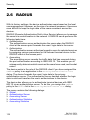
2.6
RADIUS
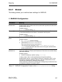
2.6.1 Global
2.6.2 Authentication Server
2.6.3 Accounting Server
2.6.4 Authentication Statistics
2.6.5 Accounting Statistics
116
117
118
120
122
123
2.7
Pre-login Banner
125
3
Time
3.1
Basic Settings
3.1.1 Global
3.1.2 Daylight Saving Time
128
128
130
3.2
SNTP
3.2.1 Client
3.2.2 Server
134
134
139
4
Network Security
4.1
DoS
4.1.1 Global
144
144
5
Switching
149
5.1
Global
150
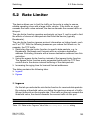
5.2
Rate Limiter
153
5.3
Filter for MAC addresses
156
5.4
IGMP
5.4.1
5.4.2
5.4.3
5.4.4
160
161
166
170
173
5.5
VLAN
5.5.1 Global
5.5.2 Current
5.5.3 Static
4
127
Snooping
IGMP Snooping Enhancements
IGMP Querier
Multicasts
143
175
176
177
179
RM GUI RSPL
Release 2.0 02/2013
Contents
5.5.4 Port
5.5.5 Voice
181
183
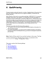
6
QoS/Priority
6.1
Global
188
6.2
Port Configuration
190
6.3
802.1D/p Mapping
193
6.4
IP DSCP Mapping
195
6.5
Queue Management
197
7
Redundancy
7.1
MRP
200
7.2
Spanning Tree
7.2.1 Global
7.2.2 Port
204
205
210
8
Diagnostics
219
8.1
System
8.1.1 System Information
8.1.2 Configuration Check
8.1.3 Selftest
220
220
221
223
8.2
Report
8.2.1 Global
8.2.2 Email Logging: Global
8.2.3 Email Logging: Addresses
8.2.4 Syslog
8.2.5 Persistent Logging
8.2.6 Hardware State
8.2.7 System Log
8.2.8 Audit Trail
226
227
232
237
238
240
243
244
245
8.3
Ports
8.3.1
8.3.2
8.3.3
8.3.4
246
246
247
248
249
8.4
Status Configuration
8.4.1 Device Status
8.4.2 Security Status
8.4.3 Signal Contact
8.4.4 MAC Notification
8.4.5 Alarms (Traps)
RM GUI RSPL
Release 2.0 02/2013
Statistics Table
Utilization
SFP
TP cable diagnosis
187
199
263
264
269
274
280
282
5
Contents
8.5
LLDP
8.5.1 Configuration
8.5.2 Topology Discovery
9
Advanced
9.1
DHCP L2 Relay
9.1.1 Configuration
9.1.2 Statistics
294
295
297
9.2
Telnet Client
298
A
Appendix
299
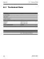
A.1
Technical Data
300
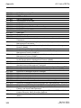
A.2
List of RFCs
301
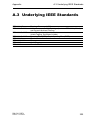
A.3
Underlying IEEE Standards
303
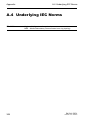
A.4
Underlying IEC Norms
304
A.5
Underlying ANSI Norms
305
A.6
Maintenance
306
A.7
Literature references
307
A.8
Copyright of Integrated Software
A.8.1 lighttpd
A.8.2 Expat
A.8.3 libcurl
A.8.4 libssh2
A.8.5 OpenSSH
A.8.6 OpenSSL
A.8.7 Parts of the FreeBSD IP stack
308
308
309
310
311
312
322
325
B
Index
327
C
Readers’ Comments
330
D
Further Support
333
6
284
284
288
293
RM GUI RSPL
Release 2.0 02/2013
About this Manual
About this Manual
The “GUI” reference manual contains detailed information on using the
graphical interface to operate the individual functions of the device.
The “Command Line Interface” reference manual contains detailed
information on using the Command Line Interface to operate the individual
functions of the device.
The “Installation” user manual contains a device description, safety
instructions, a description of the display, and the other information that you
need to install the device.
The “Basic Configuration” user manual contains the information you need to
start operating the device. It takes you step by step from the first startup
operation through to the basic settings for operation in your environment.
The “Redundancy Configuration” user manual document contains the
information you require to select the suitable redundancy procedure and
configure it.
The “HiView” user manual contains information for using the HiView GUI
application. This application allows you to use the graphical user interface of
Hirschmann devices with management independently of other applications,
such as a browser.
RM GUI RSPL
Release 2.0 02/2013
7
About this Manual
The Industrial HiVision Network Management Software provides you with
additional options for smooth configuration and monitoring:
8
Simultaneous configuration of multiple devices
Graphical user interface with network layout
Auto-topology discovery
Event log
Event handling
Client/server structure
Browser interface
ActiveX control for SCADA integration
SNMP/OPC gateway.
RM GUI RSPL
Release 2.0 02/2013
Key
Key
The designations used in this manual have the following meanings:
List
Work step
Subheading
Link
Note:
Cross-reference with link
A note emphasizes an important fact or draws your attention to a dependency.
Courier
ASCII representation in user interface
RM GUI RSPL
Release 2.0 02/2013
9
Key
10
RM GUI RSPL
Release 2.0 02/2013
Graphical User Interface
Graphical User Interface
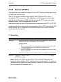
System requirements
To open the graphical user interface, you need a Web browser, for
example Mozilla Firefox version 3.5 or later, or Microsoft Internet Explorer
version 6 or later.
Installation
Note: The graphical user interface uses Java 6 or Java 7.
Install the software from the enclosed CD-ROM. To do this, you go to
“Additional Software”, select Java Runtime Environment and click on
“Installation”.
RM GUI RSPL
Release 2.0 02/2013
11
Graphical User Interface
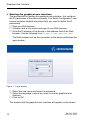
Starting the graphical user interface
The prerequisite for starting the graphical user interface, first configure
the IP parameters of the device correctly. The “Basic Configuration” user
manual contains detailed information that you need to define the IP
parameters.
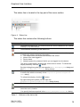
Start your Web browser.
Activate Java in the security settings of your Web browser.
Write the IP address of the device in the address field of the Web
browser. Use the following form: https://xxx.xxx.xxx.xxx
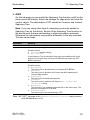
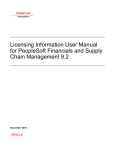
The Web browser sets up the connection to the device and shows the
login window.
Figure 1: Login window
Select the user name and enter the password.
Select the language in which you want to use the graphical user
interface.
Click on OK.
The window with the graphical user interface will appear on the screen.
12
RM GUI RSPL
Release 2.0 02/2013
Graphical User Interface
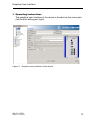
Operating Instructions
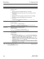
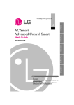
The graphical user interface of the device is divided into the menu part
(left) and the dialog part (right).
Figure 2: Graphical user interface of the device
RM GUI RSPL
Release 2.0 02/2013
13
Graphical User Interface
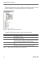
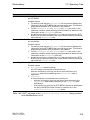
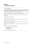
The menu shows the menu items. When you click a menu item, the user
interface displays the corresponding dialog in the dialog area.
Figure 3: Menu section with context menu
You right-click the menu section to open the context menu.
Designation
Expand All
Collaps All
Expand Node
Back
Forward
Table 1:
14
Meaning
Expands the nodes in the menu tree. The menu section shows the
menu items for all levels.
Collapses the nodes in the menu tree. The menu section shows the
menu items for the top level.
Expands the selected node and collapses the other nodes in the
menu tree. This function allows you to expand a main node without
scrolling and without collapsing other nodes manually.
Allows you to quickly jump back to a previously selected menu
item.
Allows you to quickly jump forward to a previously selected menu
item when you have previously used the "Back" function.
Menu section: Functions in the context menu
RM GUI RSPL
Release 2.0 02/2013
Graphical User Interface
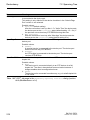
The status line is located in the top part of the menu section.
Figure 4: Status line
The status line contains the following buttons:
Button
Function
Refreshes the status line. The buttons show the values loaded from the volatile
memory (RAM) of the device.
Terminates the refreshing of the status line.
When you position the mouse pointer over the button, the user interface opens
a bubble help with the following information:
The time at which the device last refreshed the values
Name of the user logged in
Device name
Network protocol by means of which you are logged in to the device.
The device automatically refreshes the values once a minute. To refresh the
display manually, click the
button.
By right-clicking this symbol you can open the Basic Settings:System dialog and
the Basic Settings:Network:Global dialog directly.
When you position the mouse pointer over the button, the user interface opens
a bubble help with the summary of the Diagnostics:System:Configuration
Check dialog.
To refresh the display, click the
button.
By right-clicking this symbol you can open the
Diagnostics:System:Configuration Check dialog directly.
Ends the session and terminates the connection to the device.
Shows the time in seconds after which the device automatically ends the session
when the user is inactive.
You specify the timeout period in the Security:Management Access:Web dialog.
Table 2:
Buttons in the status line
RM GUI RSPL
Release 2.0 02/2013
15
Graphical User Interface
Button
Function
Shows that the configuration profile in the volatile memory (RAM) differs from the
"selected" configuration profile in the permanent memory (NVM). Save the current
device configuration permanently so that the current settings will still be available
to you after a restart.
To permanently save the changes, choose the "selected" configuration profile in
the Basic Settings:Load/Save dialog and click "Save".
The device automatically compares the configuration profiles once a minute. To
refresh the display manually, click the
button. If the device configurations
match, the button is hidden.
By right-clicking this symbol you can open the Basic Settings:Load/Save dialog
directly.
When you position the mouse pointer over the button, the user interface opens
a bubble help with the following information:
The "Last Update" section shows the time at which the device last refreshed
the values.
The "Device Status" section shows a compressed view of the "Device
Status" frame in the Basic Settings:System dialog. The section shows the
alarm that is currently active and whose occurrence was recorded first.
The "Security Status" section shows a compressed view of the "Security
Status" frame in the Basic Settings:System dialog. The section shows the
alarm that is currently active and whose occurrence was recorded first.
The "Boot Parameter" section shows a note if you permanently save
changes to the device configuration and at least one boot parameter differs
from the device configuration used during the last restart.
The following settings cause the boot parameters to change:
– Basic Settings:External Memory dialog, "Enable Automatic Software
Update" parameter
– Basic Settings:External Memory dialog, "Config Priority" parameter
– Security:Management Access:Server dialog, "SNMP" tab page, "Port
Number" parameter
– Diagnostics:System:Selftest dialog, "RAM Test" parameter
– Diagnostics:System:Selftest dialog, "Activate SysMon1" parameter
– Diagnostics:System:Selftest dialog, "Load default config on error"
parameter
Table 2:
Buttons in the status line (cont.)
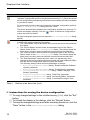
Instructions for saving the device configuration
To copy changed settings to the volatile memory (RAM), click the "Set"
button.
To refresh the display in the dialogs, click the "Reload" button
To keep the changed settings even after restarting the device, click the
"Save" button in the Basic Settings:Load/Save dialog.
16
RM GUI RSPL
Release 2.0 02/2013
Graphical User Interface
Note: Unintentional changes to the device configuration may cause the
connection between your PC and the device to be terminated. Before you
change the settings in the device, switch on the function "Undo
Modifications of Configuration" in the Basic Settings:Load/Save dialog.
With this function, the device restores the active device configuration
saved in the NVM if the connection is interrupted after the settings have
been changed. The device remains reachable.
RM GUI RSPL
Release 2.0 02/2013
17
Graphical User Interface
18
RM GUI RSPL
Release 2.0 02/2013
Basic Settings
1 Basic Settings
With this menu you can configure the basic settings of the device.
The menu contains the following dialogs:
System
Network
Software
Load/Save
External Memory
Port Configuration
Restart
RM GUI RSPL
Release 2.0 02/2013
19
Basic Settings
1.1 System
1.1 System
With this dialog you can display device properties and monitor individual
operating statuses.
Device Status
The fields in this frame show the device status and inform you about
alarms that have occurred. You define the parameters that the device
monitors in the Diagnostics:Status Configuration:Device Status
dialog.
Parameters
Symbol
Alarm Start Time
Meaning
Shows the device status.
Possible values:
The device status is OK. The monitored parameters have the
desired status.
An alarm has occurred. At least one monitored parameter differs
from the desired status.
Shows the time at which the device triggered the alarm with the current
highest priority.
Possible values:
Date and time in the format Month, Day, Year
AM/PM.
Alarm Reason
Table 3:
hh:mm:ss
The device triggers an alarm if a monitored parameter differs from the
desired status. In the Diagnostics:Status Configuration:Device Status
dialog, the parameters are sorted by priority: High priority at the top, low
priority at the bottom.
Shows the cause of the alarm and the current highest priority.
"Device Status" frame in the Basic Settings:System dialog
Note: The device reports an alarm if you only connect one power supply
unit for the supply voltage to a device with multiple ports. To avoid this
alarm, you deactivate the monitoring of the missing power supply units in
the Diagnostics:Status Configuration:Device Status dialog.
20
RM GUI RSPL
Release 2.0 02/2013
Basic Settings
1.1 System
Security Status
The fields in this frame show the security status and inform you about
alarms that have occurred. You define the parameters that the device
monitors in the Diagnostics:Status Configuration:Security Status
dialog.
Parameters
Symbol
Alarm Start Time
Meaning
Shows the security status.
Possible values:
The device status is OK. The monitored parameters have the
desired status.
An alarm has occurred. At least one monitored parameter differs
from the desired status.
Shows the time at which the device triggered the alarm with the current
highest priority.
Possible values:
Date and time in the format Month, Day, Year
AM/PM.
Alarm Reason
Table 4:
hh:mm:ss
The device triggers an alarm if a monitored parameter differs from the
desired status. In the Diagnostics:Status Configuration:Security
Status dialog, the parameters are sorted by priority: High priority at the
top, low priority at the bottom.
Shows the cause of the alarm and the current highest priority.
"Security Status" frame in the Basic Settings:System dialog
System Data
The fields in this frame show operating data and information on the
location of the device.
Parameters
Name
Meaning
Defines the device name.
Location
Possible values:
0..255 alphanumeric characters
Defines the location of the device.
Possible values:
0..255 alphanumeric characters
Table 5:
"System Data" frame in the Basic Settings:System dialog
RM GUI RSPL
Release 2.0 02/2013
21
Basic Settings
Parameters
Contact
Device Type
Power Supply P1
Power Supply P2
1.1 System
Meaning
Defines the contact person for this device.
Possible values:
0..255 alphanumeric characters
Shows the product name of the device.
Shows the status of the power supply unit on voltage supply
connection P1.
Possible values:
Present
Not present
Defective
Shows the status of the power supply unit on voltage supply
connection P2.
Possible values:
Present
Not present
Defective
Shows the time that has elapsed since this device was last
restarted.
Uptime
Temperature (°C)
Possible values:
Time in the format day(s), hh:mm:ss
The middle field shows the current temperature in the device in °C.
This field specifies the lower temperature threshold in °C.
If the temperature in the device falls below this value, the
device generates an alarm.
This field specifies the upper temperature threshold in °C.
If the temperature in the device exceeds this value, the
device generates an alarm.
Possible values:
-99..99 (integer)
You activate the monitoring of the temperature thresholds in the
Diagnostics:Status Configuration:Device Status dialog.
The “Installation” user manual contains detailed information about
setting the temperature thresholds.
Table 5:
22
"System Data" frame in the Basic Settings:System dialog (cont.)
RM GUI RSPL
Release 2.0 02/2013
Basic Settings
1.1 System
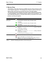
Device View
The display in this frame shows a simplified version of the structure of the
device and its equipment. The display also shows the states of the device
status LEDs and the device ports at the time of the last update.
The following symbols represent the status of the individual device ports.
In some situations, some of these symbols interfere with one another. You
get a detailed description of the port status when you position the mouse
pointer over the port symbol.
Criterion
Bandwidth of the
device port
Symbol
10 Mbit/s
Port activated, connection okay, full-duplex mode
100 Mbit/s
Port activated, connection okay, full-duplex mode
Operating state
1000 Mbit/s
Port activated, connection okay, full-duplex mode
Half-duplex mode activated
See the Basic Settings:Port Configuration dialog, "Automatic
Configuration" checkbox.
Autonegotiation activated
See the Basic Settings:Port Configuration dialog, "Automatic
Configuration" checkbox.
Port is blocked by a redundancy function.
AdminLink
Port is deactivated, connection okay
Port is deactivated, no connection set up
See Basic Settings:Port Configuration dialog, "Port on"
checkbox and "Link/Current Settings" field.
Table 6:
Symbols identifying the status of the device ports
RM GUI RSPL
Release 2.0 02/2013
23
Basic Settings
1.1 System
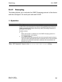
Reloading
The graphical user interface automatically updates the display of the
dialog every 100 seconds. In the process, it updates the fields and
symbols with the values that are saved in the volatile memory (RAM) of the
device. At the bottom left of the dialog, you will find the time of the next
update.
Figure 5: Time to next Reload
Note: The graphical user interface uses this function to update only the
display in the Basic Settings:System dialog.
Buttons
Button
Set
Meaning
Transfers the changes to the volatile memory (RAM) of the device. To
permanently save the changes afterwards, you open the Basic
Settings:Load/Save dialog and click "Save".
Updates the fields with the values that are saved in the volatile memory
(RAM) of the device.
Opens the online help.
Reload
Help
Table 7:
24
Buttons
RM GUI RSPL
Release 2.0 02/2013
Basic Settings
1.2 Network
1.2 Network
This dialog allows you to define settings for the access to the device
management via the network. In addition, you see the addresses of the
neighboring devices attached to the device and can detect and resolve
address conflicts.
The menu contains the following dialogs:
Global
ARP Table
IP Address Conflict Detection
RM GUI RSPL
Release 2.0 02/2013
25
Basic Settings
1.2.1
1.2 Network
Global
This dialog allows you to define basic settings with which you access the
device management via the network.
Management interface
This frame allows you to define the following settings:
The source from which the device management receives its IP
parameters
VLAN in which the management can be accessed
Parameters
IP Address
Assignment
Meaning
Defines the source from which the device receives its IP parameters after
starting:
Possible values:
BOOTP
The device receives its IP parameters from a BOOTP or DHCP server.
The server evaluates the MAC address of the device, then assigns the
IP parameters.
DHCP (default setting)
The device receives its IP parameters from a DHCP server.
The server evaluates the MAC address, the DHCP name, or other
parameters of the device, then assigns the IP parameters.
Local
The device uses the IP parameters from the internal memory. You
define the settings for this in the "IP Parameter" frame.
Note: If there is no response from the BOOTP or DHCP server, the device
sets the IP address to 0.0.0.0 and makes another attempt to obtain a valid
IP address.
VLAN ID
Defines the ID of the VLAN in which the device management can be
accessed via the network.
Possible values:
1..4042 (default setting: 1)
MAC Address
Table 8:
26
You can only access the management via the network via device ports
that are members of this VLAN. You can see which VLAN a device port is
assigned to in the Switching:VLAN:Current dialog.
Displays the MAC address of the device. The device management can be
accessed via the network using the MAC address.
"Management Interface" frame in the Basic Settings:Network:Global
dialog
RM GUI RSPL
Release 2.0 02/2013
Basic Settings
1.2 Network
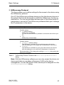
HiDiscovery Protocol
This frame allows you to define settings for the access to the device using
the HiDiscovery protocol.
On a PC the HiDiscovery software shows you the Hirschmann devices in
the network that can be accessed on which the HiDiscovery function is
switched on. You can access these devices even if they have invalid IP
parameters or none at all. The HiDiscovery software allows you to change
the IP parameters in the device.
Parameters
Operation
Meaning
Activates/deactivates the HiDiscovery function in the device.
Access
Possible values:
On (default setting)
HiDiscovery is activated.
You can use the HiDiscovery software to access the device from your
PC.
Off
HiDiscovery is deactivated.
Activates/deactivates the write access to the device using HiDiscovery.
Possible values:
readWrite (default setting)
The HiDiscovery software is given write access to the device.
With this setting you can change the IP parameters in the device.
readOnly
The HiDiscovery software is given only read access to the device.
With this setting you can view the IP parameters in the device.
Recommendation: Only change the setting to readOnly after putting the
device into operation.
Table 9:
"HiDiscovery Protocol" frame in the Basic Settings:Network:Global
dialog
Note: With the HiDiscovery software you can only access the device via
device ports that are members of the same VLAN as the device
management. You can see which VLAN a device port is assigned to in the
Switching:VLAN:Current dialog.
RM GUI RSPL
Release 2.0 02/2013
27
Basic Settings
1.2 Network
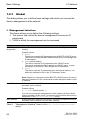
BOOTP/DHCP
Parameters
Client ID
Meaning
Shows the DHCP client ID that the device sends to the BOOTP or DHCP
server. If the server is configured accordingly, it reserves an IP address for
this DHCP client ID. Therefore, the device receives the same IP from the
server every time it requests it.
The DHCP client ID that the device sends is the device name defined in
the "Name" field in the Basic Settings:System dialog.
Table 10: "BOOTP/DHCP" frame in the Basic Settings:Network:Global dialog
IP Parameter
This frame allows you to assign the IP parameters manually. These fields
can be edited if you have selected the Local option in the "IP Address
Assignment" field in the "Management Interface" frame.
Parameters
IP Address
Netmask
Gateway Address
Meaning
Defines the IP address under which the device management can be
accessed via the network.
Possible values:
Valid IPv4 address
Default setting: —
Defines the netmask.
The netmask identifies the network prefix and the host address of the
device in the IP address.
Possible values:
Valid IPv4 netmask
Default setting: —
Defines the IP address of a router via which the device accesses other
devices outside its own network.
Possible values:
Valid IPv4 address
Default setting: —
Table 11: "IP Parameter" frame in the Basic Settings:Network:Global dialog
28
RM GUI RSPL
Release 2.0 02/2013
Basic Settings
1.2 Network
Buttons
Button
Set
Meaning
Transfers the changes to the volatile memory (RAM) of the device. To
permanently save the changes afterwards, you open the Basic
Settings:Load/Save dialog and click "Save".
Updates the fields with the values that are saved in the volatile memory
(RAM) of the device.
Opens the online help.
Reload
Help
Table 12: Buttons
1.2.2
ARP Table
This dialog allows you to display the MAC and IP addresses of the
neighboring devices connected to the device. The device determines these
addresses using the Address Resolution Protocol (ARP) before the
connection to the corresponding neighboring device is set up for the first
time.
Table
Parameters
Port
MAC Address
IP Address
Meaning
Number of the device port to which the table entry relates.
Shows the MAC address of a device that responded to an ARP query to
this device port.
Shows the IP address of a device that responded to an ARP query to this
device port.
Table 13: Table in the Basic Settings:Network:ARP Table dialog.
RM GUI RSPL
Release 2.0 02/2013
29
Basic Settings
Parameters
Type
1.2 Network
Meaning
Displays the type of the address entry.
Possible values:
static
Static ARP entry. This entry is kept when the ARP table is deleted.
dynamic
Dynamic entry. The device deletes this entry when the “Aging Time”
has been exceeded, if the device does not receive any data from this
device during this time.
Table 13: Table in the Basic Settings:Network:ARP Table dialog. (cont.)
To reset the counters, click "Reset ARP table" in the Basic
Settings:Restart dialog.
Buttons
Button
Reload
Help
Meaning
Updates the fields with the values that are saved in the volatile memory
(RAM) of the device.
Opens the online help.
Table 14: Buttons
30
RM GUI RSPL
Release 2.0 02/2013
Basic Settings
1.2.3
1.2 Network
IP Address Conflict Detection
The device allows you to detect whether another device in the network is
using its own IP address. Whenever the device detects an address conflict,
the status LED of the device flashes red 4 times.
In this dialog you specify the procedure with which the device detects
address conflicts and define the required settings for this. In the table the
device logs instances of another device in the network using its own IP
address.
Operation
Parameters
Operation
Meaning
When this function is switched on, the device detects whether another
device in the network is using its own IP address.
Possible values:
On (default setting)
The address conflict detection is switched on.
Off
The address conflict detection is switched off.
Table 15: "Operation" frame in the Basic Settings:Network:IP Address Conflict
Detection dialog
RM GUI RSPL
Release 2.0 02/2013
31
Basic Settings
1.2 Network
Configuration
Parameters
Detection Mode
Meaning
Specifies the procedure with which the device detects address conflicts.
Possible values:
Active and Passive (default setting)
The device uses active and passive address conflict detection.
Active
Active address conflict detection. The device actively avoids
communicating with an IP address that already exists in the network.
The address conflict detection begins as soon as you connect the
device to the network or change its IP parameters.
– The device sends 4 ARP probe data packets at the interval
defined in the "Detection Delay [ms]" field. If the device receives a
response to these data packets, there is an address conflict.
– If the device does not detect an address conflict, it sends 2
gratuitous ARP data packets as an announcement. The device
also sends these data packets when the address conflict
detection is switched off.
– If the IP address already exists in the network, the device changes
back to the previously used IP parameters (if possible).
If the device receives its IP parameters from a DHCP server, it
sends a DHCPDECLINE message back to the DHCP server.
– After the period specified in the "Release Delay [s]" field, the
device checks whether the address conflict still exists. If the
device detects 10 address conflicts one after the other, it extends
the waiting time until the next check to 60 s.
– When the address conflict has been resolved, the device
management returns to the network again.
Passive
Passive address conflict detection. The device analyzes the data
traffic in the network. If another device in the network is using the
device’s own IP address, the device initially “defends” its IP address.
The device stops sending if the other device then keeps sending with
the same IP address.
– As a “defence” the device sends gratuituous ARP data packets.
The device repeats this procedure for the number of times
specified in the "Number of Address Protections" field.
– If the other device continues sending with the same IP address,
after the period specified in the "Release Delay [s]" field, the
device periodically checks whether the address conflict still exists.
– When the address conflict has been resolved, the device
management returns to the network again.
Table 16: "Configuration" frame in the Basic Settings:Network:IP Address
Conflict Detection dialog
32
RM GUI RSPL
Release 2.0 02/2013
Basic Settings
1.2 Network
Parameters
Meaning
Send Periodic ARP Switches the periodic address conflict detection on/off.
Probes
Possible values:
On (default setting)
The periodic address conflict detection is switched on.
– The device periodically sends an ARP probe data packet every 90
to 150 seconds and waits for the time specified in the "Detection
Delay [ms]" field for a response.
– If the device detects an address conflict, it applies the passive
detection mode function. If the "Send Trap" function is switched
on, it sends an SNMP message (trap).
Off
The continuous address conflict detection is switched off.
Detection Delay
Defines the period in milliseconds for which the device waits for a
[ms]
response after sending an ARP data packet.
Release Delay [s]
Possible values:
20..500 (default setting: 200)
Defines the period in seconds after which the device checks again
whether the address conflict still exists.
Possible values:
3..3600 (default setting: 15)
Number of Address Defines how often the device sends gratuitous ARP data packets in the
Protections
passive detection mode to “defend” its IP address.
Protection
Interval [ms]
Send Trap
Possible values:
0..100 (default setting: 3)
Defines the period in milliseconds after which the device sends gratuitous
ARP data packets again in the passive detection mode to “defend” its IP
address.
Possible values:
20..5000 (default setting: 200)
Activates/deactivates the sending of an SNMP message (trap) when the
device detects an address conflict during the periodic address conflict
detection.
Possible values:
Selected
The device sends an SNMP message.
Not selected (default setting)
The device does not send an SNMP message.
The prerequisite for sending SNMP messages (traps) is that the function
is switched on in the Diagnostics:Status Configuration:Alarms (Traps)
dialog and at least 1 SNMP manager is defined.
Table 16: "Configuration" frame in the Basic Settings:Network:IP Address
Conflict Detection dialog (cont.)
RM GUI RSPL
Release 2.0 02/2013
33
Basic Settings
1.2 Network
Information
Parameters
Conflict detected
Meaning
Shows whether an address conflict currently exists.
Possible values:
Selected
The device detects an address conflict.
Not selected (default setting)
The device does not detect an address conflict.
Table 17: "Information" frame in the Basic Settings:Network:IP Address
Conflict Detection dialog
Table
Parameters
Time Stamp
Port
IP Address
MAC Address
Meaning
Shows the time at which the device detected an address conflict.
Shows the number of the device port on which the device detected the
address conflict.
Shows the IP address that is causing the address conflict.
Shows the MAC address of the device with which the address conflict
exists.
Table 18: Table in the Basic Settings:Network:IP Address Conflict Detection
dialog
Buttons
Button
Set
Reload
Help
Meaning
Transfers the changes to the volatile memory (RAM) of the device. To
permanently save the changes afterwards, you open the Basic
Settings:Load/Save dialog and click "Save".
Updates the fields with the values that are saved in the volatile memory
(RAM) of the device.
Opens the online help.
Table 19: Buttons
34
RM GUI RSPL
Release 2.0 02/2013
Basic Settings
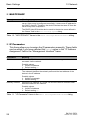
1.3 Software
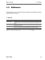
1.3 Software
This dialog allows you to update the device software and display information
about the device software.
Version
Parameters
Stored Version
Export
Running Version
Bootcode
Meaning
Shows the version number and creation date of the device software stored
in the flash memory. The device loads the device software during the next
restart.
Exports the "Stored Version" of the device software and saves it as an
image file on your PC.
Shows the version number and creation date of the device software that
the device loaded during the last restart and is currently running.
Shows the version number and creation date of the boot code.
Table 20: "Version" frame in the Basic Settings:Software dialog
RM GUI RSPL
Release 2.0 02/2013
35
Basic Settings
1.3 Software
Software Update
Parameters
File
…
Update
Meaning
Defines the path and the file name of the image file with which you update
the device software.
The device gives you the following options for updating the device
software:
File upload
If the file is located on your PC or on a network drive, click " … " and
select the file there.
TFTP upload
If the file is located on a TFTP server, enter the URL for the file in the
following form:
tftp://<IP address>/<path>/<file name>.
SCP or SFTP upload
If the file is located on an SCP or SFTP server, enter the URL for the
file in one of the following forms:
– scp:// or sftp://<IP address>/<path>/<file name>
When you click "Update", the device displays the "Authentication"
dialog. There you enter the "User" and "Password" to login to the
server.
– scp://or sftp://<user>:<password>@<IP
address>/<path>/<file name>
Shows the "Open" dialog. If the image file is located on your PC or on a
network drive, you select the image file here.
Updates the device software. In the process, the device copies the
selected file into the flash memory and replaces the device software
stored there.
The device copies the existing "Stored Version" of the device software into
the backup area.
The device loads the updated device software during the next restart.
Table 21: "Software Update" frame in the Basic Settings:Software dialog
36
RM GUI RSPL
Release 2.0 02/2013
Basic Settings
1.3 Software
Table
Parameters
File Location
Index
File name
Firmware
Applet
Logic
Meaning
Shows the storage location of the device software.
Possible values:
RAM
Volatile memory of the device
FLASH
Non-volatile memory (NVM) of the device
SD CARD
External SD memory (ACA31)
Shows the index of the device software.
Shows the device-internal file name of the device software.
Shows the version number and creation date of the device software.
Shows the version number of the graphical user interface (GUI).
Shows the version number of the logic module for devices with
programmable hardware (FPGA).
Table 22: Table in the Basic Settings:Software dialog.
Buttons
Button
Reload
Help
Meaning
Updates the fields with the values that are saved in the volatile memory
(RAM) of the device.
Opens the online help.
Table 23: Buttons
RM GUI RSPL
Release 2.0 02/2013
37
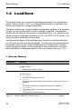
Basic Settings
1.4 Load/Save
1.4 Load/Save
This dialog allows you to save the settings permanently in a configuration
profile. When you click "Set" in a dialog while the device is operating, the
device only saves the changes temporarily.
The device allows you to keep multiple configuration profiles in the memory
so that you can quickly switch to other settings if required. Configuration
profiles can be saved in encrypted or unencrypted form. You also have the
option to export configuration profiles to a PC or an SCP or FTP server, or to
copy them back to the device from there.
Unintentional changes to the settings may cause the connection between
your PC and the device to be terminated. To make sure the device remains
accessible, switch on the "Undo Modifications of Configuration" function
before changing settings. If the connection is then terminated, the device
loads the device configuration saved in the non-volatile memory (NVM).
External Memory
Parameters
Selected ENVM
Meaning
Shows the type of the external memory.
State
Possible values:
SD
External SD memory (ACA31).
Shows the operating state of the external memory.
Possible values:
notPresent
No external memory connected.
removed
Someone has removed the external memory from the device during
operation.
ok
The external memory is connected and ready for operation.
outOfMemory
The memory space is occupied on the external memory.
genericErr
The device has detected an error.
Table 24: "External Memory" frame in the Basic Settings:Load/Save dialog
38
RM GUI RSPL
Release 2.0 02/2013
Basic Settings
1.4 Load/Save
Configuration encryption
Parameters
Active
Meaning
Shows whether the configuration encryption is switched on in the device.
Possible values:
Not selected
The configuration encryption is switched off.
The device loads a configuration from the non-volatile memory (NVM)
only if it is unencrypted.
Selected
The configuration encryption is switched on.
The device loads a configuration from the non-volatile memory (NVM)
only if it is encrypted and the password matches the password stored
in the device.
If the "Config Priority" field has the value first, second or third and
the configuration profile is unencrypted, the "Security Status" frame in the
Basic Settings:System dialog shows an alarm. In the "Monitoring" frame
in the Diagnostics:Status Configuration:Security Status dialog, you
specify whether the device monitors the parameter "Config load from
external NVM unsecure".
Table 25: "Configuration Encryption" frame in the Basic Settings:Load/Save dialog
(section #x3c;$tblsheetnum> of 2)
RM GUI RSPL
Release 2.0 02/2013
39
Basic Settings
Parameters
Set Password
1.4 Load/Save
Meaning
Encrypts configuration profiles and uses a password to make
unauthorized access more difficult.
Enter the new password in the "Set Password" dialog.
When you are changing an existing password, you also enter the
existing password.
Select the "Save Configuration afterwards" checkbox to use
encryption for the "Selected" configuration profile in the non-volatile
memory (NVM) and in the external memory (ENVM).
Note: Only use this function if a maximum of 1 configuration profile is
stored in the non-volatile memory (NVM) of the device. Before creating
additional configuration profiles, decide for or against permanently
activated configuration encryption in the device. Save additional
configuration profiles either unencrypted or encrypted with the same
password.
If you are replacing a device with an encrypted configuration profile, e.g.
due to a defect, you proceed as follows:
Restart the new device and assign the IP parameters.
Open the Basic Settings:Load/Save dialog on the new device.
Encrypt the configuration profile in the new device - see above. Enter
the same password you used in the existing device.
Install the external memory from the existing device in the new device.
Restart the new device.
When it is restarted, the device loads the configuration profile with the
settings of the existing device from the external memory (ENVM). The
device copies the settings into the volatile memory (RAM) and into the
non-volatile memory (NVM).
Note: The prerequisite for loading a configuration profile from the external
memory (ENVM) is that the "Config Priority" field in the Basic
Settings:External Memory dialog has the value first.
In the state on delivery, this value is preset.
Delete
Cancels the configuration encryption in the device.
Enter the existing password in the "Remove" dialog.
Select the "Save Configuration afterwards" checkbox to also remove
the encryption for the "Selected" configuration profile in the nonvolatile memory (NVM) and in the external memory (ENVM).
Note: If you are keeping other configuration profiles in encrypted form in
the memory, the device prevents you afterwards from activating these
configuration profiles or designating them as "Selected".
Table 25: "Configuration Encryption" frame in the Basic Settings:Load/Save dialog
(section #x3c;$tblsheetnum> of 2)
40
RM GUI RSPL
Release 2.0 02/2013
Basic Settings
1.4 Load/Save
Information
Parameters
NVM synchron to
running config
Meaning
Shows whether the configuration profile in the volatile memory (RAM) and
the "selected" configuration profile in the non-volatile memory (NVM) are
the same.
Possible values:
Selected
The configuration profiles are the same.
Not selected
The configuration profiles are different. Changes in the device are only
saved temporarily if, for example, you click on "Set" in a dialog while
the device is operating.
ENVM synchron to Shows whether the "selected" configuration profile in the external memory
NVM
(ENVM) and the "selected" configuration profile in the non-volatile memory
(NVM) are the same.
Possible values:
Selected
The configuration profiles are the same.
Not selected
The configuration profiles are different.
Possible causes:
– No external memory is connected to the device.
– In the Basic Settings:External Memory dialog, the "Auto-save
config on ENVM" function is activated.
Table 26: "Information" frame in the Basic Settings:Load/Save dialog
RM GUI RSPL
Release 2.0 02/2013
41
Basic Settings
1.4 Load/Save
Undo Modifications of Configuration
Parameters
Operation
Meaning
When a user switches on the function, the device continuously checks
whether it can still be reached from the IP address of the user. If the
connection is lost, after a defined time period the device loads the
"Selected" configuration profile from the non-volatile memory (NVM).
Afterwards, the device can be accessed again.
Possible values:
On
Function is switched on:
– You define the time period between the loss of the connection and
the loading of the configuration profile in the field "Period to undo
while Connection is lost [s]".
– If the non-volatile memory (NVM) contains multiple configuration
profiles, the device loads the configuration profile designated as
"Selected".
Off (default setting)
Function is switched off.
Switch the function off again before you close the graphical user
interface. You thus prevent the device from restoring the configuration
profile designated as "Selected".
Note: Before you switch on the function, save the settings in the
configuration profile. Therefore, current changes that are only saved
temporarily in the device are kept.
Period to undo while Specifies the time in seconds after which the device loads the "selected"
Connection is lost configuration profile from the non-volatile memory (NVM) if the connection
[s]
is lost.
Possible values:
30..600 (default setting: 600)
Watchdog IP
Address
Specify a sufficiently large value. Take into account the time when you are
only viewing the dialogs of the graphical user interface without changing
or updating them.
Shows the IP address of the PC on which you have activated the function.
Possible values:
IPv4 address (default setting: 0.0.0.0)
Table 27: "Undo Modification of Configuration" frame in the Basic
Settings:Load/Save dialog
42
RM GUI RSPL
Release 2.0 02/2013
Basic Settings
1.4 Load/Save
Table
Parameters
Storage Type
Meaning
Shows the storage location of the configuration profile.
Name
Possible values:
RAM (volatile memory of the device)
In the volatile memory the device stores the settings for the current
operation.
NVM (non-volatile memory of the device)
From the non-volatile memory the device loads the "Selected"
configuration profile during a restart or when applying the function
"Undo Modification of Configuration".
The non-volatile memory provides space for multiple configuration
profiles, depending on the number of settings saved in the
configuration profile.
The device manages a maximum of 20 configuration profiles in the
non-volatile memory.
If you select a configuration profile in the table and click "Activate", the
device loads this configuration profile to the volatile memory (RAM).
ENVM (external memory)
On the external memory the device saves a backup copy of the
"Selected" configuration profile.
The prerequisite for this is that checkmark is selected in the "Autosave config on ENVM" field in the Basic Settings:External Memory
dialog.
Shows the name of the configuration profile.
Modification Date
Possible values:
running-config
Name of the configuration profile in the volatile memory (RAM).
config
Name of the factory setting configuration profile in the non-volatile
memory (NVM).
User-defined name
The device allows you to save a configuration profile with a userdefined name by selected an existing configuration profile in the table
and clicking "Save As…".
Shows the time at which a user last saved the configuration profile.
Table 28: Table in the Basic Settings:Load/Save dialog (section
#x3c;$tblsheetnum> of 3)
RM GUI RSPL
Release 2.0 02/2013
43
Basic Settings
Parameters
Selected
1.4 Load/Save
Meaning
Shows whether the configuration profile is designated as "Selected".
Possible values:
Selected
The configuration profile is designated as "Selected".
– The device loads the configuration profile into the volatile memory
(RAM) during the restart or when applying the function "Undo
Modification of Configuration".
– When you click "Save", the device saves the temporarily saved
settings in this configuration profile.
Not selected
Another configuration profile is designated as "Selected".
Encrypted
To designate another configuration profile as "Selected", you select the
desired configuration profile in the table and click "Select".
Shows whether the configuration profile is encrypted.
Possible values:
Selected
The configuration profile is encrypted.
Not selected
The configuration profile is unencrypted.
You activate/deactivate the encryption of the configuration profile in the
"Configuration Encryption" frame.
Encryption Verified Shows whether the password of the encrypted configuration profile
matches the password stored in the device.
Software Version
Fingerprint
Possible values:
Selected
The passwords match. The device is able to unencrypt the
configuration profile.
Not selected
The passwords are different. The device is unable to unencrypt the
configuration profile.
Shows the version number of the device software that the device ran when
it saved the configuration profile.
Shows the checksum saved in the configuration profile.
The device calculates the checksum when saving the settings and inserts
it into the configuration profile.
Table 28: Table in the Basic Settings:Load/Save dialog (section
#x3c;$tblsheetnum> of 3)
44
RM GUI RSPL
Release 2.0 02/2013
Basic Settings
1.4 Load/Save
Parameters
Meaning
Fingerprint Verified Shows whether the checksum in the configuration profile is valid.
The device calculates the checksum again and compares it with the
checksum in the configuration profile.
Possible values:
Selected
The saved settings are consistent. The checksums match.
Not selected
The configuration profile contains modified settings. The checksums
are different.
Possible causes:
– The file is damaged.
– The file system on the external memory is inconsistent.
– A user has exported the configuration profile and changed the
XML file outside the device.
Note: This function identifies changes to the settings in the configuration
profile. The function does not provide protection against operating the
device with modified settings.
Table 28: Table in the Basic Settings:Load/Save dialog (section
#x3c;$tblsheetnum> of 3)
Buttons
Button
Set
Reload
Save
Meaning
Transfers the changes to the volatile memory (RAM) of the device. To
permanently save the changes afterwards, you open the Basic
Settings:Load/Save dialog and click "Save".
Updates the fields with the values that are saved in the volatile memory
(RAM) of the device.
Transfers the settings from the volatile memory (RAM) into the
configuration profile designated as "Selected" in the non-volatile memory
(NVM).
If the checkbox in the "Auto-save config on ENVM" field is selected in the
Basic Settings:External Memory dialog, the device generates a copy of
the configuration profile on the external memory.
Table 29: Buttons (section #x3c;$tblsheetnum> of 5)
RM GUI RSPL
Release 2.0 02/2013
45
Basic Settings
Button
Activate
1.4 Load/Save
Meaning
Loads the settings of the configuration profile selected in the table to the
volatile memory (RAM).
The device terminates the connection to the graphical user interface.
Reload the graphical user interface.
Login again.
The device immediately uses the settings of the configuration profile
in the current operation.
Switch on the function "Undo Modifications of Configuration" before you
activate another configuration profile. If the connection is lost afterwards,
the device loads the last configuration profile designated as "Selected"
from the non-volatile memory (NVM). The device can then be accessed
again.
If the configuration encryption is inactive, the device loads the
configuration profile only if it is unencrypted. If the configuration encryption
is active, the device loads the configuration profile only if it is encrypted
and the password matches the password stored in the device.
Delete
When you activate an older configuration profile, the device takes over the
settings of the functions contained in this software version. The device
sets the settings of newer functions to the state on delivery.
Removes the configuration profile selected in the table from the nonvolatile memory (NVM) or from the external memory (ENVM).
If the configuration profile is designated as "Selected", the device prevents
you from removing the configuration profile.
Table 29: Buttons (section #x3c;$tblsheetnum> of 5)
46
RM GUI RSPL
Release 2.0 02/2013
Basic Settings
Button
Select
1.4 Load/Save
Meaning
Designates the configuration profile selected in the table as "Selected". In
the "Selected" column, the checkbox is now selected.
The device loads the settings of this configuration profile to the volatile
memory (RAM) during the restart or when applying the function "Undo
Modification of Configuration".
Only designate an unencrypted device configuration as "Selected"
when the configuration encryption in the device is switched off.
Only designate an encrypted device configuration as "Selected" when
the following prerequisites are fulfilled:
– The configuration encryption in the device is switched on.
– The password of the configuration profile matches the password
stored in the device.
Otherwise the device is unable to load and encrypt the settings in the
configuration profile the next time it restarts. For this case you specify in
the Diagnostics:System:Selftest dialog whether the device starts with
the factory settings or terminates the restart and stops.
Note: Only configuration profiles in the non-volatile memory (NVM) can be
designated as "Selected".
If the checkbox in the "Auto-save config on ENVM" field is selected in the
Basic Settings:External Memory dialog, the device also designates the
Export...
configuration profile with the same name on the external memory as
"Selected".
Opens a menu with the following buttons.
Exports the configuration profile selected in the table and saves it as an
XML file on the PC or on a server.
The device gives you the following options for exporting a configuration
profile:
Download to PC
To save the file on your PC or on a network drive, click " … " and select
the directory there.
Download to a TFTP server
To save the file on a TFTP server, enter the URL for the file in the
following form:
tftp://<IP address>/<path>/<file name>.
Download to an SCP or SFTP server
To save the file on an SCP or SFTP server, enter the URL for the file
in one of the following forms:
– scp:// or sftp://<IP address>/<path>/<file name>
When you click "OK", the device displays the "Authentication"
window. There you enter the "User" and "Password" to login to the
server.
– scp://or sftp://<user>:<password>@<IP
address>/<path>/<file name>
Table 29: Buttons (section #x3c;$tblsheetnum> of 5)
RM GUI RSPL
Release 2.0 02/2013
47
Basic Settings
Button
Import...
1.4 Load/Save
Meaning
Imports a configuration profile saved in XML format from a PC or from a
server in the network.
You specify the storage location for the configuration profile to be
imported in the "Storage Type" field.
You specify the name of the configuration profile to be imported in the
"Name" field.
The device gives you the following options for importing a configuration
profile:
File upload
If the file is located on your PC or on a network drive, click " … " and
select the file there.
TFTP upload
If the file is located on a TFTP server, enter the URL for the file in the
following form:
tftp://<IP address>/<path>/<file name>.
SCP or SFTP upload
If the file is located on an SCP or SFTP server, enter the URL for the
file in one of the following forms:
– scp:// or sftp://<IP address>/<path>/<file name>
When you click "Update", the device displays the "Authentication"
dialog. There you enter the "User" and "Password" to login to the
server.
– scp://or sftp://<user>:<password>@<IP
address>/<path>/<file name>
View...
Save As...
If the configuration encryption is inactive, the device imports the
configuration profile only if it is unencrypted. If the configuration encryption
is active, the device imports the device configuration only if it is encrypted
and the password matches the password stored in the device.
Shows the settings of the configuration profile selected in the table in clear
text as an XML.
If the configuration profile is encrypted, enter the password in order to see
the settings in clear text.
Copies the configuration profile selected in the table and saves it with a
user-defined name in the non-volatile memory (NVM). The device
designates the new configuration profile as "Selected".
Note: Before creating additional configuration profiles, decide for or
against permanently activated configuration encryption in the device.
Save additional configuration profiles either unencrypted or encrypted with
the same password.
If the checkbox in the "Auto-save config on ENVM" field is selected in the
Basic Settings:External Memory dialog, the device also designates the
configuration profile with the same name on the external memory as
"Selected".
Table 29: Buttons (section #x3c;$tblsheetnum> of 5)
48
RM GUI RSPL
Release 2.0 02/2013
Basic Settings
Button
Back to factory
defaults...
Help
1.4 Load/Save
Meaning
Resets the settings in the device to the factory settings.
The device deletes the saved configuration profiles from the volatile
memory (RAM) and from the non-volatile memory (NVM).
If an external memory is connected, the device deletes the
configuration profiles saved on the external memory (ENVM).
After a brief period, the device restarts and loads the factory settings.
Opens the online help.
Table 29: Buttons (section #x3c;$tblsheetnum> of 5)
RM GUI RSPL
Release 2.0 02/2013
49
Basic Settings
1.5 External Memory
1.5 External Memory
This dialog allows you to activate functions that the device automatically
executes in combination with the external memory (ENVM). The dialog also
shows the operating state and identifying characteristics of the external
memory.
Table
Parameters
Type
Meaning
Shows the type of the external memory.
Status
Possible values:
SD
External SD memory (ACA31)
Shows the operating status of the external memory.
Writable
Possible values:
notPresent
No external memory connected.
removed
Someone has removed the external memory from the device during
operation.
ok
The external memory is connected and ready for operation.
outOfMemory
The memory space is occupied on the external memory.
genericErr
The device has detected an error.
Shows whether the device has write access to the external memory.
Manufacturer ID
Product Name
Version
Serial Number
Possible values:
Selected
The device has write access to the external memory.
Not selected
The device only has read access to the external memory. It is possible
that write protection is activated on the external memory.
Shows the name of the memory manufacturer.
Shows the product name specified by the memory manufacturer.
Shows the version number specified by the memory manufacturer.
Shows the serial number specified by the memory manufacturer.
Table 30: Table in the Basic Settings:External Memory dialog (section
#x3c;$tblsheetnum> of 2)
50
RM GUI RSPL
Release 2.0 02/2013
Basic Settings
Parameters
Enable Automatic
Software Update
Config Priority
1.5 External Memory
Meaning
Defines whether the device updates the device software when it restarts.
Possible values:
selected (default setting)
During a restart the device updates the device software when the
following files are located in the external memory:
– the image file of the device software
– a text file startup.txt with the content
autoUpdate=FILE_NAME_OF_THE_IMAGE_FILE
Not selected
The device performs the restart without updating the device software.
Specifies which memory the device loads the configuration profile from
when it restarts.
Possible values:
disable
The device loads the configuration profile from the non-volatile
memory (NVM).
first, second, third
The device loads the configuration profile from the external memory
(ENVM).
If the device does not find a configuration profile on the external
memory, it loads the configuration profile from the non-volatile
memory (NVM).
Note: When loading the configuration profile from the external memory
(ENVM), the device overwrites the settings of the "Selected"configuration
profile in the non-volatile memory (NVM).
If the "Config Priority" field has the value first, second or third and
the configuration profile is unencrypted, the "Security Status" frame in the
Basic Settings:System dialog shows an alarm. In the "Monitoring" frame
in the Diagnostics:Status Configuration:Security Status dialog, you
specify whether the device monitors the parameter "Config load from
external NVM unsecure".
Auto-save config on Defines whether the device generates a copy on the external memory
envm
when saving the configuration profile.
Possible values:
selected (default setting)
The device generates a copy of the configuration profile on the
external memory when you click "Save" in the Basic
Settings:Load/Save dialog.
Not selected
The device does not generate a copy of the configuration profile.
Table 30: Table in the Basic Settings:External Memory dialog (section
#x3c;$tblsheetnum> of 2)
RM GUI RSPL
Release 2.0 02/2013
51
Basic Settings
1.5 External Memory
Buttons
Button
Set
Reload
Help
Meaning
Transfers the changes to the volatile memory (RAM) of the device. To
permanently save the changes afterwards, you open the Basic
Settings:Load/Save dialog and click "Save".
Updates the fields with the values that are saved in the volatile memory
(RAM) of the device.
Opens the online help.
Table 31: Buttons
52
RM GUI RSPL
Release 2.0 02/2013
Basic Settings
1.6 Port Configuration
1.6 Port Configuration
With this dialog you can define settings for the individual device ports. The
dialog also shows the operating mode, connection state, bit rate and duplex
mode for every device port.
Table
Parameters
Port
Name
Meaning
Shows the number of the device port to which the table entry relates.
Name of the device port.
Enter the name of your choice.
Port on
Possible values:
0..64 alphanumeric characters
Activates/deactivates the device port.
State
Possible values:
Selected (default setting)
The device port is activated.
Not selected
The device port is deactivated. The device port does not send or
receive any data.
Shows whether the device port is currently physically switched on or off.
Possible values:
Selected
The device port is switched on.
Not selected
The device port is switched off.
If the "Port on" function is switched on, the "Auto Disable" function has
switched off the device port.
You define the settings for the "Auto Disable" function in the
Diagnostics:Ports:Auto Disable dialog.
Table 32: Table in the Basic Settings:Port Configuration dialog. (section
#x3c;$tblsheetnum> of 4)
RM GUI RSPL
Release 2.0 02/2013
53
Basic Settings
1.6 Port Configuration
Parameters
Power State
(Port off)
Meaning
Physically switches off the device port, or leaves it on when you deactivate
the "Port on" function.
Auto Power Down
Possible values:
Selected
The device port remains physically switched on. A connected device
receives an active link.
Not selected (default setting)
The device port is physically switched off.
Defines how the device port behaves when no cable is connected.
Automatic
Configuration
Possible values:
no-power-save (default setting)
The device port remains activated.
auto-power-down
The device port switches to the energy-saving mode.
unsupported
The device port does not support this function and remains activated.
Activates/deactivates the automatic configuration of the device port.
Possible values:
Selected (default setting)
This setting has priority over the manual configuration of the device
port.
The device port negotiates the operating mode independently using
autonegotiation and detects the devices connected to the TP port
automatically (Auto Cable Crossing).
After the function is switched on, it takes a few seconds for the device
port to set the operating mode.
Not selected
The device port works with the values you defined in the "Manual
Configuration" column and the "Manual Cable Crossing (Auto. Conf.
off)" column.
Table 32: Table in the Basic Settings:Port Configuration dialog. (section
#x3c;$tblsheetnum> of 4)
54
RM GUI RSPL
Release 2.0 02/2013
Basic Settings
Parameters
Manual
Configuration
1.6 Port Configuration
Meaning
Defines the operating mode of the device port when the automatic
configuration of the device port is deactivated.
Possible values:
10 Mbit/s HDX
Half duplex connection
10 Mbit/s FDX
Full duplex connection
100 Mbit/s HDX
Half duplex connection
100 Mbit/s FDX (default setting on TP ports)
Full duplex connection
1000 Mbit/s FDX (default setting on optical ports)
Full duplex connection
Link/Current
Settings
Manual Cable
Crossing (Auto.
Conf. off)
The operating modes actually available depend on the corresponding
media module.
Displays the currently set operating mode of the device port.
Possible values:
–
No cable connected, no link.
10 Mbit/s HDX
Half duplex connection
10 Mbit/s FDX
Full duplex connection
100 Mbit/s HDX
Half duplex connection
100 Mbit/s FDX
Full duplex connection
1000 Mbit/s FDX
Full duplex connection
Defines the devices connected to a TP port.
Prerequisite: The automatic configuration of the device port is deactivated.
Possible values:
mdi
The device switches the send and receive line pairs at the device port.
mdix (default setting on TP ports)
The device does not switch any line pairs at the device port.
auto-mdix
The device detects the send and receive line pairs of the connected
device and automatically adapts to them.
Example: When you connect a terminal device with a crossed cable,
the device automatically resets the port from MDIX to MDI.
unsupported (default setting on optical ports or TP-SFP ports)
The device port does not support this function.
Table 32: Table in the Basic Settings:Port Configuration dialog. (section
#x3c;$tblsheetnum> of 4)
RM GUI RSPL
Release 2.0 02/2013
55
Basic Settings
Parameters
Flow Control
1.6 Port Configuration
Meaning
Activates/deactivates the flow control on the device port.
Possible values:
Not selected
Flow control on the device port is deactivated.
Selected (default setting)
The sending and evaluating of pause data packets (full-duplex
operation) or collisions (half-duplex operation) is activated on the port.
To switch on the flow control in the device, also switch on the
"Activate Flow Control" function in the Switching:Global dialog.
Additionally activate the flow control on the port of the device
connected with this port.
On an uplink port, activating the flow control can possibly cause
undesired sending breaks in the higher-level network segment
(“wandering backpressure”).
When you are using a redundancy function, you deactivate the flow control
on the participating device ports. If the flow control and the redundancy
function are active at the same time, there is a risk that the redundancy
function will not operate as intended.
Table 32: Table in the Basic Settings:Port Configuration dialog. (section
#x3c;$tblsheetnum> of 4)
Buttons
Button
Set
Reload
Help
Meaning
Transfers the changes to the volatile memory (RAM) of the device. To
permanently save the changes afterwards, you open the Basic
Settings:Load/Save dialog and click "Save".
Updates the fields with the values that are saved in the volatile memory
(RAM) of the device.
Opens the online help.
Table 33: Buttons
56
RM GUI RSPL
Release 2.0 02/2013
Basic Settings
1.7 Restart
1.7 Restart
This dialog allows you to restart the device, reset port counters and address
tables, and delete log files.
Restart
Button
Cold start...
Meaning
Triggers a restart of the device.
After the start, the device goes through the following phases:
The device performs a RAM test if this function is switched on in the
Diagnostics:System:Selftest dialog.
The device starts the "Stored Version" of the device software - see the
Basic Settings:Software dialog.
The device loads the settings of the configuration profile designated
as "Selected" - see the Basic Settings:Load/Save dialog.
Note: During the restart, the device does not transfer any data. During this
time, the device cannot be accessed by the graphical user interface or
other management systems.
Table 34: "Restart" frame in the Basic Settings:Restart dialog
Buttons
Button
Reset MAC
Address Table
Meaning
Removes the MAC addresses designated with the learned setup status
from the forwarding table - see the Switching:Filter for MAC Addresses
table.
Reset ARP Table Removes the dynamically set up addresses from the ARP table - see the
Basic Settings:Network:ARP Table dialog.
Reset port counters Resets the counter for the port statistics to 0 - see the
Diagnostics:Ports:Statistics Table dialog.
Reset IGMP
Removes the IGMP Snooping entries and resets the counter in the
Snooping counters "Information" frame to 0 - see the Switching:IGMP:Snooping dialog.
Delete Log File
Removes the logged events from the log file - see the
Diagnostics:Report:System Log dialog.
Table 35: Buttons
RM GUI RSPL
Release 2.0 02/2013
57
Basic Settings
Button
Delete Persistent
Log File
Help
1.7 Restart
Meaning
Removes the log files from the external memory - see the
Diagnostics:Report:Persistent Logging dialog.
Opens the online help.
Table 35: Buttons (cont.)
58
RM GUI RSPL
Release 2.0 02/2013
Security
2 Security
This menu allows you to define the settings for the access to the device.
The menu contains the following dialogs:
User Management
Authentication List
Management Access
Port Security
802.1X Port Authentication
RADIUS
Pre-login Banner
RM GUI RSPL
Release 2.0 02/2013
59
Security
2.1 User Management
2.1 User Management
The device allows users to access its management functions when they log
in with valid login data. The device authenticates the users either using the
local user management or with a RADIUS server in the network.
In this dialog you manage the users of the local user management. You also
define the following settings here:
Settings for the login
Settings for saving the passwords
Define policy for valid passwords
Configuration
This frame allows you to define settings for the login.
Parameters
Number of Login
Attempts
Meaning
Number of login attempts possible.
Possible values:
0..5 (default setting: 0)
If the user makes one more unsuccessful login attempt, the device locks
access for the user.
The device only allows users with the Administrator access role to
remove the lock.
The value 0 deactivates the lock. The user can make unlimited attempts
to login.
Table 36: "Configuration" frame in the Security:User Management dialog
60
RM GUI RSPL
Release 2.0 02/2013
Security
2.1 User Management
Password policy
This frame allows you to define the policy for valid passwords. The device
checks every new password and password change according to this
policy.
The settings affect the "Password" field. The prerequisite is that the
"Policy Check" must be checkmarked.
Parameters
Meaning
Minimum Password The device accepts the password if it contains at least the number of
Length
characters specified here.
The device checks the password according to this setting, regardless of
the setting for the "Policy Check" checkbox.
Minimum Upper
Cases
Possible values:
6..64 (default setting: 6)
The device accepts the password if it contains at least as many uppercase letters as specified here.
Possible values:
0..16 (default setting: 1)
Minimum Lower
Cases
The value 0 deactivates this setting.
The device accepts the password if it contains at least as many lower-case
letters as specified here.
Possible values:
0..16 (default setting: 1)
The value 0 deactivates this setting.
Minimum Numbers The device accepts the password if it contains at least as many numbers
as specified here.
Possible values:
0..16 (default setting: 1)
Minimum Special
Characters
The value 0 deactivates this setting.
The device accepts the password if it contains at least as many special
characters as specified here.
Possible values:
0..16 (default setting: 1)
The value 0 deactivates this setting.
Table 37: "Password Policy" frame in the Security:User Management dialog
RM GUI RSPL
Release 2.0 02/2013
61
Security
2.1 User Management
Table
Every user requires an active user account to gain access to the
management functions of the device. The table allows you to set up and
manage user accounts.
To change settings click the desired parameter in the table and modify the
value.
Parameters
User Name
Active
Meaning
Shows the name of the user account.
To create a new user account, you click "Create".
Activates/deactivates the user account.
Possible values:
Selected
The user account is active. The user accepts the login of a user with
this user name.
Not selected
The user account is inactive. The user rejects the login of a user with
this user name.
Password
If only one user account exists with the administrator access role, this
user account is always active.
Shows ***** (asterisks) instead of the password with which the user logs
in. To change the password, click the relevant field.
Possible values:
6..64 alphanumeric characters
including the following special characters:
!#$%&'()*+,-./:;<=>?@[\\]^_`{}~
The minimum length of the password is defined in the "Password Policy"
frame. The device differentiates between upper and lower case.
When the checkbox in the "Policy Check" field is selected, the device
checks the password according to the policy defined in the "Password
Policy" frame.
The device always checks the minimum length of the password, even if
the checkbox in the "Policy Check" field is not selected.
Table 38: Table in the Security:User Management dialog (section
#x3c;$tblsheetnum> of 3)
62
RM GUI RSPL
Release 2.0 02/2013
Security
Parameters
Access Role
User locked
Policy Check
SNMP Auth Type
2.1 User Management
Meaning
Defines the access role that regulates the user’s access to the individual
functions of the device.
Possible values:
guest
The user is authorized to monitor the device.
operator
The user is authorized to monitor and configure the device - with the
exception of security settings for the access to the device.
administrator
The user is authorized to monitor and configure the device.
unauthorized
The user is locked, and the device rejects the user’s login.
You assign this value to temporarily lock the user account. If an error
occurs when another access role is being assigned, the device
assigns this access role to the user account.
Locks/unlocks the user’s access to the management functions of the
device.
Possible values:
Selected
The user’s access is locked.
The device automatically locks a user if the user makes too many
unsuccessful login attempts.
Not selected
The user’s access is unlocked.
Defines whether the device checks the password according to the defined
policy when it is being set up or changed.
Possible values:
Selected
The device checks the password according to the policy defined in the
"Password Policy" frame.
Not selected
The device accepts the password without checking it.
Defines the authentication protocol that the device applies for user access
via SNMPv3.
Possible values:
hmacmd5
For this user account, the device uses protocol HMAC-MD5.
hmacsha
For this user account, the device uses protocol HMAC-SHA.
Table 38: Table in the Security:User Management dialog (section
#x3c;$tblsheetnum> of 3)
RM GUI RSPL
Release 2.0 02/2013
63
Security
Parameters
SNMP Encryption
Type
2.1 User Management
Meaning
Defines the encryption protocol that the device applies for user access via
SNMPv3.
Possible values:
none
No encryption
des
DES encryption
aesCfb128
AES-128 encryption
Table 38: Table in the Security:User Management dialog (section
#x3c;$tblsheetnum> of 3)
New Entry
In this frame you set up a new user account. To display the frame, you
click the "Create" button.
Parameters
User Name
Meaning
Specifies the name of the user account.
Active
Possible values:
1..32 alphanumeric characters
Activates/deactivates the user account.
Possible values:
Selected
The user account is active. The user accepts the login of a user with
this user name.
Not selected
The user account is inactive. The user rejects the login of a user with
this user name.
Table 39: "New Entry" frame in the Security:User Management dialog (section
#x3c;$tblsheetnum> of 3)
64
RM GUI RSPL
Release 2.0 02/2013
Security
Parameters
Password
2.1 User Management
Meaning
Specifies the password with which the user logs in.
When the checkbox in the "Display Password" field is selected, the
password is visible in clear text.
Possible values:
6..64 alphanumeric characters
including the following special characters:
!#$%&'()*+,-./:;<=>?@[\\]^_`{}~
The minimum length of the password is defined in the "Password Policy"
frame. The device differentiates between upper and lower case.
When the checkbox in the "Policy Check" field is selected, the device
checks the password according to the policy defined in the "Password
Policy" frame.
Display Password
Access Role
User locked
The device always checks the minimum length of the password, even if
the checkbox in the "Policy Check" field is not selected.
Specifies how the adjacent "Password" field displays the password.
Possible values:
Not selected (default setting)
The "Password" field displays *** (asterisks) instead of the password.
Selected
The "Password" field displays the password in clear text.
Defines the access role profile that regulates the user’s access to the
individual functions of the device.
Possible values:
guest
The user is authorized to monitor the device.
operator
The user is authorized to monitor and configure the device - with the
exception of security settings for the access to the device.
administrator
The user is authorized to monitor and configure the device.
unauthorized
The user is blocked, and the device rejects the user’s login.
You assign this value to temporarily lock the user account. If an error
occurs when another access role is being assigned, the device
assigns this access role to the user account.
Locks/unlocks the user’s access to the management functions of the
device.
Possible values:
Selected
The user’s access is locked.
Not selected
The user’s access is unlocked.
Table 39: "New Entry" frame in the Security:User Management dialog (section
#x3c;$tblsheetnum> of 3)
RM GUI RSPL
Release 2.0 02/2013
65
Security
Parameters
Policy Check
SNMP Auth Type
SNMP Encryption
Type
2.1 User Management
Meaning
Defines whether the device checks the password according to the defined
policy when it is being set up or changed.
Possible values:
Selected
The device checks the password according to the policy defined in the
"Password Policy" frame.
Not selected
The device accepts the password without checking it.
Defines the authentication protocol that the device applies for user access
via SNMPv3.
Possible values:
hmacmd5
For this user account, the device uses protocol HMAC-MD5.
hmacsha
For this user account, the device uses protocol HMAC-SHA.
Defines the encryption protocol that the device applies for user access via
SNMPv3.
Possible values:
none
No encryption
des
DES encryption
aesCfb128
AES-128 encryption
Table 39: "New Entry" frame in the Security:User Management dialog (section
#x3c;$tblsheetnum> of 3)
Buttons
Button
Set
Set and back
Back
Reload
Remove
Create
Help
Meaning
Transfers the changes to the volatile memory (RAM) of the device. To
permanently save the changes afterwards, you open the Basic
Settings:Load/Save dialog and click "Save".
Transfers the changes to the volatile memory (RAM) of the device and goes
back to the previous dialog.
Displays the previous dialog again. Changes are lost.
Updates the fields with the values that are saved in the volatile memory
(RAM) of the device.
Removes the selected table entry.
Adds a new table entry.
Opens the online help.
Table 40: Buttons
66
RM GUI RSPL
Release 2.0 02/2013
Security
2.2 Authentication List
2.2 Authentication List
The device only allows users to access its management functions when they
log in with valid login data. The device authenticates the users either using
the local user management or with a RADIUS server in the network.
With the port-based access control according to IEEE 802.1X, the device
only allows connected terminal devices to access the network when they log
in with valid login data. The device authenticates the terminal devices either
with a RADIUS server in the network or with an integrated authentication
server implemented in the device.
In this dialog you manage the authentication lists. In a list you define which
method the device uses for the authentication. Here you have the option to
differentiate the application with which the device is accessed, e.g. via a
console or with the graphical user interface.
Table
Parameters
Name
Meaning
Shows the name of the list.
To create a new list, you click "Create".
Table 41: Table in the Security:Authentication List dialog
RM GUI RSPL
Release 2.0 02/2013
67
Security
Parameters
Policy 1
Policy 2
Policy 3
Policy 4
Policy 5
Dedicated
Applications
Active
2.2 Authentication List
Meaning
Shows the authentication method that the device uses for access via the
application specified in the "Dedicated Applications" field. To change the
value, click the relevant field.
The device gives you the option of a fall-back solution. For this, you
specify one other method in each of the "Policy 2" to "Policy 5" fields. If the
authentication with the specified method is not successful, the device uses
the next policy.
Possible values:
local
The device authenticates the users by using the local user
management - see the Security:User Management dialog.
radius
The device authenticates the users with a RADIUS server in the
network. You specify the RADIUS server in the
Security:RADIUS:Authentication Server dialog.
ias
The device authenticates the terminal devices logging in via 802.1X
with the integrated authentication server (IAS) implemented in the
device. The integrated authentication server manages the login data
in a separate database - see the Security:802.1X Port
Authentication:Integrated Authentication Server dialog.
reject
The device rejects the authentication request from the user.
Shows the dedicated applications. When users access the device with the
relevant application, the device uses the defined policies for the
authentication.
To allocate another application to the list or remove the allocation, you
click "Allocate Applications". Every application can always be allocated to
exactly one list.
Activates/deactivates the list.
Possible values:
Selected
The list is activated. The device uses the policies in this list when
users access the device with the relevant application.
Not selected
The list is deactivated.
Table 41: Table in the Security:Authentication List dialog (cont.)
Note: If the table does not contain a list, it is only possible to access the
device using CLI via the V.24 interface. In this case, the device
authenticates the user by using the local user management - see the
Security:User Management dialog.
68
RM GUI RSPL
Release 2.0 02/2013
Security
2.2 Authentication List
New Entry
In this frame you set up a new authentication list. To display the frame,
you click the "Create" button.
Parameters
Name
Policy 1
Policy 2
Policy 3
Policy 4
Policy 5
Active
Meaning
Specifies the name of the list.
Possible values:
1..32 alphanumeric characters
Specifies the authentication method that the device uses.
The device gives you the option of a fall-back solution. For this, you
specify one other method in each of the "Policy 2" to "Policy 5" fields.
Possible values:
local
The device authenticates the users by using the local user
management - see the Security:User Management dialog.
radius
The device authenticates the users with a RADIUS server in the
network. You specify the RADIUS server in the
Security:RADIUS:Authentication Server dialog.
ias
The device authenticates the terminal devices logging in via 802.1X
with the integrated authentication server (IAS) implemented in the
device. The integrated authentication server manages the login data
in a separate database - see the Security:802.1X Port
Authentication:Integrated Authentication Server dialog.
reject
The device rejects the authentication request from the user.
Activates/deactivates the list.
Possible values:
Selected
The list is activated. The device uses the policies in this list when
users access the device with the relevant application.
Not selected
The list is deactivated.
Table 42: "New Entry" frame in the Security:Authentication List dialog
RM GUI RSPL
Release 2.0 02/2013
69
Security
2.2 Authentication List
Allocate Applications
In this frame you specify the accesses for which the device uses the
selected list. For example, to only use the list for accesses via the V.24
interface, you assign the Console (V.24) application.
To display the frame, you click the "Allocate Applications" button.
Parameters
Description
Possible Applications This column contains the applications that can be allocated to the
selected list.
Possible values:
Console (V.24)
for accessing the management via the V.24 interface
SSH
for accessing the management via SSH
Telnet
for accessing the management via Telnet
Web Interface
for accessing the management via the graphical user interface
8021x
for accessing the network via 802.1X
Note: Every application can always be allocated to exactly one list. It is
possible that the applications in this column are already allocated to
another list. If you allocate an application to the list that is already
allocated to another list, the device removes the original allocation.
Dedicated
Applications
This column contains the applications that are allocated to the selected
list.
Table 43: "Allocate Applications" frame in the Security:Authentication List
dialog
Buttons
Button
Set
Set and back
Back
Meaning
Transfers the changes to the volatile memory (RAM) of the device. To
permanently save the changes afterwards, you open the Basic
Settings:Load/Save dialog and click "Save".
Transfers the changes to the volatile memory (RAM) of the device and goes
back to the previous dialog.
Displays the previous dialog again. Changes are lost.
Table 44: Buttons
70
RM GUI RSPL
Release 2.0 02/2013
Security
Button
Reload
Remove
Create
Allocate
Applications
Help
>
>>
<
<<
2.2 Authentication List
Meaning
Updates the fields with the values that are saved in the volatile memory
(RAM) of the device.
Removes the selected table entry.
Adds a new table entry.
Displays the "Allocate Applications" dialog.
Opens the online help.
Moves the selected entry to the right column.
Moves all entries to the right column.
Moves the selected entry to the left column.
Moves all entries to the left column.
Table 44: Buttons (cont.)
RM GUI RSPL
Release 2.0 02/2013
71
Security
2.3 Management Access
2.3 Management Access
This dialog allows you to set up the server services with which users or
applications can access the management functions of the device. You also
have the option of restricting the access for IP address ranges and individual
management services.
The menu contains the following dialogs:
Server
SNMPv1/v2 Community
IP Access Restriction
Web
CLI
2.3.1
Server
This dialog allows you to set up the server services with which users or
applications can access the management functions of the device.
The dialog contains the following tabs:
Server: SNMP
Server: Telnet
Server: HTTP
Server: HTTPS
Server: SSH
72
RM GUI RSPL
Release 2.0 02/2013
Security
2.3.2
2.3 Management Access
Server: SNMP
This tab allows you to define settings for the SNMP server of the device and
to switch on/off the access to the device with different SNMP versions.
The SNMP server enables access to the management functions of the
device with SNMP-based applications, e.g. with the graphical user interface.
Configuration
Parameters
SNMPv1 enabled
Meaning
Activates/deactivates the access to the device with SNMP version 1.
Possible values:
Selected (default setting)
Access activated.
Not selected
Access deactivated.
You define the community name in the Security:Management
Access:SNMPv1/v2 Community dialog.
SNMPv2 enabled
Activates/deactivates the access to the device with SNMP version 2.
Possible values:
Selected (default setting)
Access activated.
Not selected
Access deactivated.
You define the community name in the Security:Management
Access:SNMPv1/v2 Community dialog.
SNMPv3 enabled
Activates/deactivates the access to the device with SNMP version 3.
Possible values:
Selected (default setting)
Access activated.
Not selected
Access deactivated.
This function is used, for example, by the Industrial HiVision network
management software to make changes to the settings.
Table 45: "Configuration" frame in the Security:Management Access:Server dialog,
"SNMP" tab page
RM GUI RSPL
Release 2.0 02/2013
73
Security
Parameters
Port number
2.3 Management Access
Meaning
Defines the number of the UDP port from which the SNMP server receives
requests from clients.
Possible values:
1..65535 (default setting: 161)
Exception: Port 2222 is reserved for internal functions.
SNMPover802
enabled
To get the server to use the new port after a change, you proceed as
follows:
Click on "Set".
Select the active device configuration in the Basic
Settings:Load/Save dialog and click "Save".
Restart the device.
Activates/deactivates the access with SNMP via IEEE 802 networks.
Possible values:
not selected (default setting)
Access deactivated.
selected
Access activated.
This function uses, for example, the HiDiscovery software to configure
devices without an IP address.
Table 45: "Configuration" frame in the Security:Management Access:Server dialog,
"SNMP" tab page (cont.)
Buttons
Button
Set
Reload
Help
Meaning
Transfers the changes to the volatile memory (RAM) of the device. To
permanently save the changes afterwards, you open the Basic
Settings:Load/Save dialog and click "Save".
Updates the fields with the values that are saved in the volatile memory
(RAM) of the device.
Opens the online help.
Table 46: Buttons
74
RM GUI RSPL
Release 2.0 02/2013
Security
2.3.3
2.3 Management Access
Server: Telnet
This tab allows you to define settings for the Telnet server of the device and
to switch the server on/off.
The Telnet server enables access to the management functions of the device
with the Command Line Interface via a Telnet connection.
Operation
Parameters
Operation
Meaning
If the function is switched on, the Telnet server is activated.
Possible values:
Off
Server is deactivated.
On (default setting)
Server is activated. You can access the management functions of the
device via Telnet.
Table 47: "Operation" frame in the Security:Management Access:Server dialog,
"Telnet" tab page
Configuration
Parameters
Listen TCP Port
Meaning
Defines the number of the TCP port from which the server receives
requests from clients.
Possible values:
1..65535 (default setting: 23)
Exception: Port 2222 is reserved for internal functions.
Connection Count
The server restarts automatically after the port is changed. Existing
connections remain in place.
Shows how many clients are currently logged on to the server.
Possible values:
0..5
Table 48: "Configuration" frame in the Security:Management Access:Server dialog,
"Telnet" tab page (section #x3c;$tblsheetnum> of 2)
RM GUI RSPL
Release 2.0 02/2013
75
Security
Parameters
Max. Number of
Connections
Session Timeout
[min]
2.3 Management Access
Meaning
Defines how many clients can be logged on to the server at the same time.
Possible values:
0..5
Defines the timeout in minutes. After the device has been inactive for this
time it ends the session for the user logged on.
Possible values:
0..160 (default setting: 5)
The value 0 deactivates the function. The user remains logged on when
inactive.
Table 48: "Configuration" frame in the Security:Management Access:Server dialog,
"Telnet" tab page (section #x3c;$tblsheetnum> of 2)
Buttons
Button
Set
Reload
Help
Meaning
Transfers the changes to the volatile memory (RAM) of the device. To
permanently save the changes afterwards, you open the Basic
Settings:Load/Save dialog and click "Save".
Updates the fields with the values that are saved in the volatile memory
(RAM) of the device.
Opens the online help.
Table 49: Buttons
76
RM GUI RSPL
Release 2.0 02/2013
Security
2.3.4
2.3 Management Access
Server: HTTP
This tab allows you to define settings for the HTTP server of the device and
to switch the server on/off.
The HTTP server provides the graphical user interface (GUI) via an HTTP
connection. The graphical user interface communicates with the device
based on SNMP and enables access to the management functions.
The device supports up to 10 simultaneous connections via HTTP or HTTPS.
Operation
Parameters
Operation
Meaning
When the function is switched on, the device supplies the graphical user
interface (GUI) via an HTTP connection.
Possible values:
Off
Server is deactivated.
On (default setting)
Server is activated. You can access the management functions of the
device via HTTP.
Table 50: "Operation" frame in the Security:Management Access:Server dialog,
"HTTP" tab page
Configuration
Parameters
Listen TCP Port
Meaning
Defines the number of the TCP port on which the server receives requests
from clients.
Possible values:
1..65535 (default setting: 80)
Exception: Port 2222 is reserved for internal functions.
The server restarts automatically after the port is changed. In the process,
the device terminates open connections to the server.
Table 51: "Configuration" frame in the Security:Management Access:Server dialog,
"HTTP" tab page
RM GUI RSPL
Release 2.0 02/2013
77
Security
2.3 Management Access
Buttons
Button
Set
Reload
Help
Meaning
Transfers the changes to the volatile memory (RAM) of the device. To
permanently save the changes afterwards, you open the Basic
Settings:Load/Save dialog and click "Save".
Updates the fields with the values that are saved in the volatile memory
(RAM) of the device.
Opens the online help.
Table 52: Buttons
78
RM GUI RSPL
Release 2.0 02/2013
Security
2.3.5
2.3 Management Access
Server: HTTPS
This tab allows you to define settings for the HTTPS server of the device and
to switch the server on/off.
The HTTP server provides the graphical user interface (GUI) via an
encrypted HTTP connection. The graphical user interface communicates
with the device based on SNMP via the encrypted HTTP connection and
enables access to the management functions.
The device supports up to 10 simultaneous connections via HTTP or HTTPS.
A digital certificate is required for the encryption of the HTTP connection. The
device allows you to create this certificate yourself or to load an existing
certificate onto the device.
Operation
Parameters
Operation
Meaning
When the function is switched on, the device supplies the graphical user
interface (GUI) via an encrypted HTTP connection.
Possible values:
Off
Server is deactivated. The management functions of the device can
only be accessed via the Command Line Interface (CLI).
On (default setting)
Server is activated. You can access the management functions of the
device via HTTPS.
The device can then only be started if there is a certificate on the device.
Table 53: "Operation" frame in the Security:Management Access:Server dialog,
"HTTPS" tab page
Note: When you switch off the server, the connection between the
graphical user interface (GUI) and the device is interrupted. To continue
working with the graphical user interface, switch the server on again via
the Command Line Interface (CLI).
RM GUI RSPL
Release 2.0 02/2013
79
Security
2.3 Management Access
Configuration
Parameters
Listen TCP Port
Meaning
Defines the number of the TCP port on which the server receives requests
from clients.
Possible values:
1..65535 (default setting: 443)
Exception: Port 2222 is reserved for internal functions.
The server restarts automatically after the port is changed. In the process,
the device terminates open connections to the server.
Table 54: "Configuration" frame in the Security:Management Access:Server dialog,
"HTTPS" tab page
Certificate
Parameters
Present
Meaning
Shows whether the digital certificate is present in the device.
Create
Possible values:
Selected
The certificate is present.
Not selected
The certificate has been removed.
Creates a digital certificate on the device.
To get the server to use this certificate, you click "Set" and restart the
server. You can only restart the server via the Command Line Interface
(CLI).
Delete
Alternatively, you can copy your own certificate to the device - see the
"Certificate Import" dialog.
Deletes the digital certificate.
To permanently remove the certificate from the device, save the changes.
In the process, the device switches off the HTTPS server.
Table 55: "Certificate" frame in the Security:Management Access:Server dialog,
"HTTPS" tab page
Note: In the Web browser, a warning appears when you are loading the
graphical user interface if you are using a certificate that has not been
verified by a certifying organization. To load the graphical user interface,
add an exception rule for the certificate in the Web browser.
80
RM GUI RSPL
Release 2.0 02/2013
Security
2.3 Management Access
Certificate Import
Parameters
URL
…
Import
Meaning
Defines the path and file name of the certificate.
X.509 certificates (PEM) are permitted.
The device gives you the following options for copying the certificate to the
device:
File upload
If the certificate is on your PC or on a network drive, click " … " and
select the file that contains the signature key.
TFTP upload
If the certificate is on a TFTP server, enter the URL for the file in the
following form: tftp://<IP address>/<path>/<file name>.
SCP or SFTP upload
If the certificate is on an SCP or SFTP server, you enter the URL for
the file in the following form:
– scp:// or sftp://<IP address>/<path>/<file name>
When you click "Import...", the device displays the
"Authentication" window. There you enter the "User" and
"Password" to login to the server.
– scp://or sftp://<user>:<password>@<IP
address>/<path>/<file name>
Shows the "Open" dialog. Here you select the certificate file to be copied
if the file is located on your PC or on a network drive.
Copies the certificate defined in the "File" field to the device.
To get the server to use this certificate, you click "Set" and restart the
server. You can only restart the server via the Command Line Interface
(CLI).
Table 56: "Certificate Import" frame in the Security:Management Access:Server
dialog, "HTTPS" tab page
Buttons
Button
Set
Reload
Help
Meaning
Transfers the changes to the volatile memory (RAM) of the device. To
permanently save the changes afterwards, you open the Basic
Settings:Load/Save dialog and click "Save".
Updates the fields with the values that are saved in the volatile memory
(RAM) of the device.
Opens the online help.
Table 57: Buttons
RM GUI RSPL
Release 2.0 02/2013
81
Security
2.3.6
2.3 Management Access
Server: SSH
This tab allows you to switch the SSH server on/off in the device and define
its settings.
The server works with SSH version 2. The SSH server enables access to the
management functions of the device with the Command Line Interface via an
encrypted connection (secure shell).
The SSH server identifies itself to the clients using its public RSA or DSA key.
When first setting up the connection, the client program shows the user the
fingerprint of this key. The fingerprint contains a hexadecimal number
sequence that is easy to check. When you make this number sequence
available to the users via a reliable channel, they have the option to compare
both fingerprints. If the number sequences match, the client is connected to
the correct server.
The device allows you to create the private and public keys (host keys)
required for RSA and DSA directly on the device. Otherwise you have the
option to copy your own keys to the device in PEM format.
Operation
Parameters
Operation
Meaning
If the function is switched on, encrypted access to the management
functions of the device is possible via the Command Line Interface (CLI).
Possible values:
Off
Server is deactivated.
On (default setting)
Server is activated. You can access the management functions of the
device via SSH.
The server can only be started if there is an RSA or DSA signature on the
device.
When the function is switched off, existing connections remain in place.
However, the device prevents new connections from being set up.
Table 58: "Operation" frame in the Security:Management Access:Server dialog,
"SSH" tab page
82
RM GUI RSPL
Release 2.0 02/2013
Security
2.3 Management Access
Configuration
Parameters
Listen TCP Port
Meaning
Defines the number of the TCP port on which the server receives requests
from clients.
Possible values:
1..65535 (default setting: 22)
Exception: Port 2222 is reserved for internal functions.
Session Count
Max. Number of
Sessions
The server restarts automatically after the port is changed. Existing
connections remain in place.
Shows how many connections to the server are currently set up.
Defines the maximum number of connections to the server that can be set
up simultaneously.
Session Timeout
[min]
Possible values:
1..5 (default setting: 5)
Defines the timeout in minutes. After the device has been inactive for this
time it ends the session for the user logged on.
Possible values:
1..160 (default setting: 5)
The value 0 deactivates the function. The user remains logged on when
inactive.
Table 59: "Configuration" frame in the Security:Management Access:Server dialog,
"SSH" tab page
Fingerprint
The fingerprint is an easily verified hexadecimal number sequence that
uniquely identifies the RSA or DSA key (host key) of the SSH server.
Parameters
DSA
RSA
Meaning
Number sequence of the public DSA key of the server.
Number sequence of the public RSA key of the server.
Table 60: "Server" dialog, "SSH" tab, "Fingerprint" frame
After importing a new RSA or DSA key, the device continues to display
the existing fingerprint until you restart the server.
RM GUI RSPL
Release 2.0 02/2013
83
Security
2.3 Management Access
Signature
Parameters
DSA Present
Meaning
Shows whether a DSA key (host key) is present in the device.
RSA Present
Possible values:
selected
A key is present.
not selected
No key is present.
Shows whether an RSA key (host key) is present in the device.
Create
Possible values:
selected
A key is present.
not selected
No key is present.
Creates a key (host key) on the device. The device only creates the key
when the server is deactivated.
Length of the key created:
2048 bit (RSA)
1024 bit (DSA)
To get the server to use the key created, you click "Set". Then you switch
the server on.
Delete
Alternatively, you can copy your own key to the device in PEM format - see
the "Import" frame.
Removes the key (host key) from the device.
To permanently remove the key from the device, click "Set". Until you
restart the server, the existing connections remain in place. However, the
device prevents new connections from being set up.
Table 61: "Signature" frame in the Security:Management Access:Server dialog,
"SSH" tab page
84
RM GUI RSPL
Release 2.0 02/2013
Security
2.3 Management Access
Key Import
Parameters
URL
Meaning
Defines the path and file name of your own DSA/RSA key (host key).
The device accepts the DSA/RSA key if it has the following key length:
2048 bit (RSA)
1024 bit (DSA)
…
Import
The device gives you the following options for copying the key to the
device:
File upload
If the key is on your PC or on a network drive, click " … " and select
the file that contains the key (host key).
TFTP upload
If the key is on a TFTP server, enter the URL for the file in the following
form: tftp://<IP address>/<path>/<file name>.
SCP or SFTP upload
If the key is on an SCP or SFTP server, you enter the URL for the file
in the following form:
– scp:// or sftp://<IP address>/<path>/<file name>
When you click "Import...", the device displays the
"Authentication" window. There you enter the "User" and
"Password" to login to the server.
– scp://or sftp://<user>:<password>@<IP
address>/<path>/<file name>
Shows the "Open" dialog. Here you select the key to be copied if the file
is located on your PC or on a network drive.
Copies the key (host key) defined in the "File" field to the device.
To get the server to use this key, you click "Set" and restart the server.
Table 62: "Key Import" frame in the Security:Management Access:Server dialog,
"SSH" tab page
Buttons
Button
Set
Reload
Help
Meaning
Transfers the changes to the volatile memory (RAM) of the device. To
permanently save the changes afterwards, you open the Basic
Settings:Load/Save dialog and click "Save".
Updates the fields with the values that are saved in the volatile memory
(RAM) of the device.
Opens the online help.
Table 63: Buttons
RM GUI RSPL
Release 2.0 02/2013
85
Security
2.3.7
2.3 Management Access
SNMPv1/v2 Community
With this dialog you can define the community name for SNMPv1/v2
applications.
Applications send requests via SNMPv1/v2 with a community name in the
SNMP data packet header. Depending on the community name, the
application gets read authorization or read and write authorization for the
device.
You activate the access to the device via SNMPv1/v2 in the
Security:Management Access:Server dialog.
Table
Parameters
Community
Name
Meaning
Shows the authorization for SNMPv1/v2 applications to the device:
Write
For requests with the community name entered beside this, the
application gets read and write authorization for the device.
Read
For requests with the community name entered here, the application
gets read authorization for the device.
Defines the community name for the authorization entered beside it.
Possible values:
0..32 alphanumeric characters
including spaces and the following special characters:
!#$%&'()*+,-./:;<=>?@[\\]^_`{}~
private (default setting for read and write authorization)
public (default setting for read authorization)
Table 64: Table in the Security:Management Access:SNMPv1/v2 Community dialog.
Buttons
Button
Set
Meaning
Transfers the changes to the volatile memory (RAM) of the device. To
permanently save the changes afterwards, you open the Basic
Settings:Load/Save dialog and click "Save".
Table 65: Buttons
86
RM GUI RSPL
Release 2.0 02/2013
Security
2.3 Management Access
Button
Reload
Meaning
Updates the fields with the values that are saved in the volatile memory
(RAM) of the device.
Opens the online help.
Help
Table 65: Buttons (cont.)
2.3.8
IP Access Restriction
This dialog enables you to restrict the access to the management functions
of the device to specific IP address ranges and selected IP-based
applications.
If the function is switched off, you can access the management functions
of the device from any IP address and via all applications.
If the function is switched on, the access is restricted. You can only
access the management functions under the following conditions:
– At least one table entry is activated.
and
– You are accessing the device with a permitted application from a
permitted IP address range.
Operation
Parameters
Operation
Meaning
If the function is switched on, the access to the management functions of
the device is restricted.
Possible values:
Off (default setting).
On
Access to the management functions of the device is restricted.
Table 66: "Operation" frame in the Security:Management Access:IP Access
Restriction dialog
RM GUI RSPL
Release 2.0 02/2013
87
Security
2.3 Management Access
Note: Before switching on the function, make sure that at least one active
entry in the table allows you access: Otherwise the connection to the
device terminates when you change the device configuration. It is then
only possible to access the management functions using CLI via the V.24
interface of the device.
Table
You have the option of defining up to 16 table entries and activating them
separately.
Parameters
Index
Meaning
Shows a sequential number to which the table entry relates.
The device automatically defines this number.
Possible values:
1..16
IP Address Range
When you delete a table entry, this leaves a gap in the numbering. When
you create a new table entry, the device fills the first gap.
Specifies the IP address range for which you define the access to the
management functions with this table entry.
HTTP
Possible values:
Valid IPv4 address and netmask in CIDR notation
0.0.0.0/0 (default setting for all newly created entries)
Activates/deactivates the HTTP access.
HTTPS
Possible values:
selected (default setting)
Access is activated for the adjacent IP address range.
not selected
Access is deactivated.
Activates/deactivates the HTTPS access.
Possible values:
Selected (default setting)
Access is activated for the adjacent IP address range.
Not selected
Access is deactivated.
Table 67: Table in the Security:Management Access:IP Access Restriction
dialog
88
RM GUI RSPL
Release 2.0 02/2013
Security
2.3 Management Access
Parameters
SNMP
Meaning
Activates/deactivates the SNMP access.
Telnet
Possible values:
Selected (default setting)
Access is activated for the adjacent IP address range.
Not selected
Access is deactivated.
Activates/deactivates the Telnet access.
SSH
Possible values:
selected (default setting)
Access is activated for the adjacent IP address range.
not selected
Access is deactivated.
Activates/deactivates the SSH access.
Active
Possible values:
Selected (default setting)
Access is activated for the adjacent IP address range.
Not selected
Access is deactivated.
Activates/deactivates the table entry.
Possible values:
Selected (default setting)
Table entry is activated. The device restricts access to its
management functions to the adjacent IP address range and the
selected IP-based applications.
Not selected
Table entry is deactivated.
Table 67: Table in the Security:Management Access:IP Access Restriction dialog
(cont.)
In the state on delivery, there is a default entry in the table for the IP
address range 0.0.0.0/0, in which the access for all applications is
activated. This table entry allows you access to the device regardless of
your location, e.g. to initially configure the function. You have the option
to change or delete this table entry. When you create a new table entry it
has the same properties.
Note: To start the graphical user interface in a Web browser, you require
the "HTTP" or "HTTPS" service. For the graphical user interface to have
access to the device, the "SNMP" service is also required. If you are using
the graphical user interface outside the Web browser, you only require the
"SNMP" service.
RM GUI RSPL
Release 2.0 02/2013
89
Security
2.3 Management Access
Buttons
Button
Set
Meaning
Transfers the changes to the volatile memory (RAM) of the device. To
permanently save the changes afterwards, you open the Basic
Settings:Load/Save dialog and click "Save".
Updates the fields with the values that are saved in the volatile memory
(RAM) of the device.
Adds a new table entry.
Removes the selected table entry.
Opens the online help.
Reload
Create
Remove
Help
Table 68: Buttons
2.3.9
Web
With this dialog you can define settings for the graphical user interface (Webbased interface).
Configuration
Parameters
Web Interface
Session Timeout
[min]
Meaning
Defines the timeout in minutes. After the device has been inactive for this
time it ends the session for the user logged on.
Possible values:
0..160 (default setting: 5)
The value 0 deactivates the function, and the user remains logged on
when inactive.
Table 69: "Configuration" frame in the Security:Management Access:Web dialog
90
RM GUI RSPL
Release 2.0 02/2013
Security
2.3 Management Access
Buttons
Button
Set
Reload
Help
Meaning
Transfers the changes to the volatile memory (RAM) of the device. To
permanently save the changes afterwards, you open the Basic
Settings:Load/Save dialog and click "Save".
Updates the fields with the values that are saved in the volatile memory
(RAM) of the device.
Opens the online help.
Table 70: Buttons
2.3.10 CLI
With this dialog you can define settings for the Command Line Interface
(CLI). You will find detailed information on the Command Line Interface in the
“Command Line Interface” reference manual.
The dialog contains the following tabs:
CLI: Global
CLI Login Banner
RM GUI RSPL
Release 2.0 02/2013
91
Security
2.3 Management Access
2.3.11 CLI: Global
This tab allows you to change the CLI prompt and to define the automatic
closing of sessions via the V.24 interface when they have been inactive.
Configuration
Parameters
Login Prompt
Meaning
Defines the character string that the device displays in the Command Line
Interface (CLI) at the start of every command line.
Possible values:
0..32 alphanumeric characters
Default setting: (RSPL)
including spaces and the following special characters:
!#$%&'()*+,-./:;<=>?@[\\]^_`{}~
Changes to this setting are immediately effective in the active CLI session.
V.24 Timeout [min] Defines the time in minutes after which the device automatically closes the
session of a logged on user in the Command Line Interface via the V.24
interface when it has been inactive.
Possible values:
0..160 (default setting: 5)
The value 0 deactivates the function, and the user remains logged on
when inactive.
For Telnet and SSH, you define the timeout in the Security:Management
Access:Server dialog.
Table 71: "Configuration" frame in the Security:Management Access:CLI dialog,
"Global" tab page
Buttons
Button
Set
Reload
Help
Meaning
Transfers the changes to the volatile memory (RAM) of the device. To
permanently save the changes afterwards, you open the Basic
Settings:Load/Save dialog and click "Save".
Updates the fields with the values that are saved in the volatile memory
(RAM) of the device.
Opens the online help.
Table 72: Buttons
92
RM GUI RSPL
Release 2.0 02/2013
Security
2.3 Management Access
2.3.12 CLI Login Banner
This tab page allows you to replace the CLI start screen with your own text.
In the state on delivery, the CLI start screen shows information about the
device, such as the software version and the device settings. With the
function on this tab page, you deactivate this information and replace it with
an individually defined text.
To display your own text in the CLI and in the graphical user interface before
the login, you use the Security:Pre-login Banner dialog.
Operation
Parameters
Operation
Meaning
When this function is switched on, the device shows the text information
defined in the "Banner Text" field to all the users that login to the device
via the Command Line Interface (CLI).
When the function is switched off, the CLI start screen shows information
about the device. The text information in the "Banner Text" field is kept.
Possible values:
Off (default setting).
On
Table 73: "Operation" frame in the Security:Management Access:CLI dialog, "Login
Banner" tab page
Banner Text
Parameters
Banner Text
Meaning
Defines the character string that the device displays in the Command Line
Interface at the start of every command line.
Possible values:
0..1024 alphanumeric characters
including spaces, tabs, line breaks and the following special
characters:
!#$%&'()*+,-./:;<=>?@[\\]^_`{}~
Table 74: "Banner Text" frame in the Security:Management Access:CLI dialog,
"Login Banner" tab page
RM GUI RSPL
Release 2.0 02/2013
93
Security
Parameters
Remaining
Characters
2.3 Management Access
Meaning
Shows how many characters are still remaining in the "Banner Text" field
for the text information.
Table 74: "Banner Text" frame in the Security:Management Access:CLI dialog,
"Login Banner" tab page (cont.)
Buttons
Button
Set
Reload
Help
Meaning
Transfers the changes to the volatile memory (RAM) of the device. To
permanently save the changes afterwards, you open the Basic
Settings:Load/Save dialog and click "Save".
Updates the fields with the values that are saved in the volatile memory
(RAM) of the device.
Opens the online help.
Table 75: Buttons
94
RM GUI RSPL
Release 2.0 02/2013
Security
2.4 Port Security
2.4 Port Security
The device allows you to only transmit data packets from desired senders.
When this function is switched on, the device checks the VLAN ID and MAC
address of the sender before it transmits a data packet. The device discards
data packets from other senders and logs this event. This restriction makes
MAC Spoofing attacks more difficult.
In this dialog a "Wizard" helps you to connect the device ports with one or
more desired senders. In the device these addresses are known as "Static
Addresses".
To keep the setup process as simple as possible, the device allows you to
record the desired senders automatically. The device “learns” the senders by
evaluating the received data packets. In the device these addresses are
known as "Dynamic Addresses". When a user-defined upper limit has been
reached ("Dynamic Limit"), the device stops the “learning” on the relevant
port and only transmits the data packets of the senders already recorded.
When you adjust the upper limit to the number of expected senders, you thus
make MAC Flooding attacks more difficult.
Note: With the automatic recording of the "Dynamic Addresses", the device
always discards the 1st data packet from unknown senders. Using this 1st
data packet, the device checks whether the upper limit has been reached.
The device records the sender until the upper limit is reached. Afterwards,
the device transmits data packets that it receives on the relevant port from
this sender.
RM GUI RSPL
Release 2.0 02/2013
95
Security
2.4 Port Security
Operation
Parameters
Operation
Meaning
When this function is switched on, the device checks the VLAN ID and
MAC address of the sender before it transmits a data packet.
Possible values:
On
The device only transmits a received data packet if its sender is
desired on the relevant device port. Also activate the checking of the
sender on the relevant device ports.
Off (default setting)
The device transmits every received data packet without checking the
sender.
Table 76: "Operation" frame in the Security:Port Security dialog
Table
Parameters
Port
Active
Meaning
Shows the number of the device port to which the table entry relates.
Activates/deactivates the checking of the sender on the device port.
Possible values:
Selected
The device checks every data packet received on the device port and
transmits it if its sender is desired. You also switch on the function in
the "Operation" frame.
Not selected (default setting)
The device transmits every data packet received on the port without
checking the sender.
Note: If you are operating the device as an active subscriber within an
MRP ring, we recommend setting the value of the field to Not selected.
Table 77: Table in the Security:Port Security dialog
96
RM GUI RSPL
Release 2.0 02/2013
Security
Parameters
Violation Traps
2.4 Port Security
Meaning
Activates/deactivates the sending of an SNMP message (trap) when the
device discards data packets from an undesired sender on the port.
Possible values:
Selected
The device sends an SNMP message when it discards data packets
from an undesired sender on the port.
Not selected (default setting)
The device does not send any SNMP messages.
Violation Trap
Frequency [s]
The prerequisite for sending SNMP messages (traps) is that the function
is switched on in the Diagnostics:Status Configuration:Alarms (Traps)
dialog and at least 1 SNMP manager is defined.
Defines the waiting time in seconds that the device waits after sending an
SNMP message (trap) before sending the next SNMP message.
Possible values:
0..3600 (default setting: 0)
Dynamic Limit
The value 0 deactivates the waiting time.
Specifies the upper limit for the number of automatically recorded senders
("Dynamic Addresses"). When the upper limit has been reached, the
device stops the “learning” on this port.
Adjust the value to the number of expected senders.
Possible values:
0..600 (default setting: 600)
Static Limit
The value 0 deactivates the automatic recording of the senders on this
port.
Specifies the upper limit for the number of senders connected to the port
("Static Addresses"). The "Wizard" helps you to connect the port with one
or more desired senders.
Possible values:
0..64 (default setting: 64)
The value 0 prevents you from connecting a sender with the port.
Current Dynamic
Shows the number of automatically recorded senders ("Dynamic
Addresses").
Current Static
Shows the number of senders connected to the port ("Static Addresses").
Last Violating VLAN Shows the VLAN ID and MAC address of an undesired sender whose data
ID/MAC
packets the device last discarded on this port.
Trapped Violations Shows the number of discarded data packets on this device port that
caused the device to send an SNMP message (trap).
Table 77: Table in the Security:Port Security dialog (cont.)
RM GUI RSPL
Release 2.0 02/2013
97
Security
2.4 Port Security
Buttons
Button
Set
Reload
Wizard
Help
Meaning
Transfers the changes to the volatile memory (RAM) of the device. To
permanently save the changes afterwards, you open the Basic
Settings:Load/Save dialog and click "Save".
Updates the fields with the values that are saved in the volatile memory
(RAM) of the device.
Opens the "Wizard".
With the "Wizard" you assign the permitted MAC addresses to a port.
Opens the online help.
Table 78: Buttons
Wizard – Select Port
The "Wizard" helps you to connect the device ports with one or more
desired senders.
Parameters
Select Port
Meaning
Defines the device port that you assign to the sender in the next step.
Table 79: Wizard in the Security:Port Security dialog, "Select Port" page
Wizard – Addresses
The "Wizard" helps you to connect the device ports with one or more
desired senders. When you have defined the settings, click "Finish". To
save the changes afterwards, click Set in the "Security:Port Security"
dialog.
Parameters
VLAN
Meaning
Specifies the VLAN ID of the desired sender.
Possible values:
1..4042
Click "Add" to transfer the VLAN ID and the MAC address to the "Static
Addresses" field.
Table 80: Wizard in the Security:Port Security dialog, "Addresses" page
98
RM GUI RSPL
Release 2.0 02/2013
Security
Parameters
MAC Address
2.4 Port Security
Meaning
Specifies the MAC address of the desired sender.
Possible values:
Valid Unicast MAC address
Enter the value in one of the following formats:
– without a separator, e.g. 001122334455
– separated by spaces, e.g. 00 11 22 33 44 55
– separated by colons, e.g. 00:11:22:33:44:55
– separated by hyphens, e.g. 00-11-22-33-44-55
– separated by points, e.g. 00.11.22.33.44.55
– separated by points after every 4th character, e.g.
0011.2233.4455
Add
Static Addresses
Remove
<
<<
Click "Add" to transfer the VLAN ID and the MAC address to the "Static
Addresses" field.
Transfers the values specified in the "VLAN ID" and "MAC Address" fields
to the "Static Addresses" field.
Shows the VLAN ID and MAC address of desired senders connected to
the port.
The device uses this field to show the number of senders connected to the
port and the upper limit. You specify the upper limit for the number of
entries in the table, "Static Limit" field.
Removes the entries selected in the "Static Addresses" field.
Moves the entries selected in the "Dynamic Addresses" field to the "Static
Addresses" field.
Moves every entry from the "Dynamic Addresses" field to the "Static
Addresses" field.
If the "Dynamic Addresses" field contains more entries than are allowed in
the "Static Addresses" field, the device moves the foremost entries until
the upper limit is reached.
Dynamic Addresses Shows in ascending order the VLAN ID and MAC address of the senders
automatically recorded on this port. The device transmits data packets
from these senders when it receives the data packets on this port.
You specify the upper limit for the number of entries in the table, "Dynamic
Limit" field.
The " < " and " << " buttons allow you to transfer entries from this
field into the "Static Addresses" field. In this way, you connect relevant
sender with the port.
Table 80: Wizard in the Security:Port Security dialog, "Addresses" page (cont.)
Button
Back
Next
Finish
Meaning
Displays the previous page again. Changes are lost.
Saves the changes and opens the next page.
Saves the changes and completes the configuration.
Table 81: Buttons
RM GUI RSPL
Release 2.0 02/2013
99
Security
Button
Cancel
2.4 Port Security
Meaning
Closes the Wizard. Changes are lost.
Table 81: Buttons (cont.)
After closing the Wizard, click "Set" to save your settings.
Note: The device stores the senders connected with the port until you
deactivate the checking of the sender on the relevant port or in the
"Operation" frame.
100
RM GUI RSPL
Release 2.0 02/2013
Security
2.5 802.1X Port Authentication
2.5 802.1X Port Authentication
With the port-based access control according to IEEE 802.1X, the device
monitors the access to the network from connected terminal devices. The
device (authenticator) only allows a terminal device (supplicant) to access
the network when it logs in with valid login data. The authenticator and the
terminal devices communicate via the EAPoL (Extensible Authentication
Protocol over LANs) authentication protocol.
The device supports the following methods to authenticate terminal devices:
radius
A RADIUS server in the network authenticates the terminal devices.
ias
The Integrated Authentication Server (IAS) implemented in the device
authenticates the terminal devices. Compared to RADIUS, the IAS only
provides basic functions.
The menu contains the following dialogs:
802.1X Global
Port Configuration
Port Clients
Statistics
Port Authentication History
Integrated Authentication Server
RM GUI RSPL
Release 2.0 02/2013
101
Security
2.5.1
2.5 802.1X Port Authentication
802.1X Global
With this dialog you can define basic settings for the port-based access
control.
Operation
Parameters
Operation
Meaning
When this function is switched on, the device checks the access to the
network from connected terminal devices.
Possible values:
On
The port-based access control is activated.
Off (default setting)
The port-based access control is deactivated.
Table 82: "Operation" frame in the Security:802.1X Port Authentication:Global
dialog
Configuration
Parameters
Activate VLAN
Assignment
Meaning
When this function is switched on, the RADIUS authentication server
assigns the relevant device port to a VLAN. This function allows you to
provide selected services to the connected terminal device in this VLAN.
Possible values:
Not selected (default setting)
The function is deactivated. The relevant device port is assigned to the
VLAN specified in the Security:802.1X Port Authentication:Port
Configuration dialog, "Assigned VLAN ID" column.
Selected
The function is activated. If the terminal device successfully
authenticates itself, the device assigns to the relevant device port the
VLAN ID transferred by the RADIUS authentication server.
Table 83: "Configuration" frame in the Security:802.1X Port
Authentication:Global dialog
102
RM GUI RSPL
Release 2.0 02/2013
Security
Parameters
Activate Dynamic
VLAN Creation
Activate Monitor
Mode
2.5 802.1X Port Authentication
Meaning
When this function is switched on, the device creates the VLAN assigned
by the RADIUS authentication server if it does not exist.
Possible values:
Not selected (default setting)
The function is deactivated. If the assigned VLAN does not exist, the
port remains assigned to the original VLAN.
Selected
The function is activated. The device creates the VLAN if it does not
exist.
Activates/deactivates the Telnet access.
When the monitor mode is switched on, the device monitors the
authentication and helps with error diagnostics. If a terminal device has
not logged in successfully, the device gives the terminal device access to
the network.
Possible values:
Not selected (default setting)
The monitor mode is switched off.
Selected
The monitor mode is switched on.
Table 83: "Configuration" frame in the Security:802.1X Port
Authentication:Global dialog (cont.)
Information
Parameters
Monitor Mode
Clients
Meaning
Shows the number of terminal devices to which the device gave network
access even though they did not login successfully. The prerequisite is
that the "Activate Monitor Mode" function is switched on - see the
"Configuration" frame.
Non Monitor Mode Shows the number of terminal devices to which the device gave network
Clients
access after they logged in successfully.
Authentication
Shows the method that the device currently uses to authenticate the
Method
terminal devices using IEEE 802.1X.
You specify the method to be used in the Security:Authentication List
dialog.
To authenticate the terminal devices via a RADIUS server, you assign
the radius policy to the 8021x list.
To authenticate the terminal devices via the Integrated Authentication
Server (IAS) you assign the ias policy to the 8021x list.
Table 84: "Information" frame in the Security:802.1X Port
Authentication:Global dialog
RM GUI RSPL
Release 2.0 02/2013
103
Security
2.5 802.1X Port Authentication
Buttons
Button
Set
Meaning
Transfers the changes to the volatile memory (RAM) of the device. To
permanently save the changes afterwards, you open the Basic
Settings:Load/Save dialog and click "Save".
Updates the fields with the values that are saved in the volatile memory
(RAM) of the device.
Opens the online help.
Reload
Help
Table 85: Buttons
2.5.2
Port Configuration
This dialog allows you to define the access settings for every device port.
Table
Parameters
Port
Port Initialization
Meaning
Shows the number of the device port to which the table entry relates.
Initializes the device port in order to activate the access control on the port
or reset it to its initial state. Only use this function if the value auto is
specified for the port in the "Port Control" column.
Possible values:
Not selected (default setting)
Keeps the current state of the device port.
Selected
Initializes the device port.
When the initialization is complete, the device changes the value to
Not selected again.
Table 86: Table in the Security:802.1X Port Authentication:Port
Configuration dialog. (section #x3c;$tblsheetnum> of 5)
104
RM GUI RSPL
Release 2.0 02/2013
Security
Parameters
Port
Reauthentication
2.5 802.1X Port Authentication
Meaning
If this function is switched on, the authenticator requests the terminal
device to login again. Only use this function if the value auto is specified
for the port in the "Port Control" column.
Possible values:
Not selected (default setting)
Keeps the terminal device logged in.
Selected
Requests the terminal device to login again. Afterwards, the device
changes the value to Not selected again.
Authentication
Activity
Backend
Authentication
State
Authentication
State
The device also allows you to periodically request the terminal device to
login again - see the "Reauthentication Enabled" column.
Displays the current state of the authenticator (authenticator PAE state).
Possible values:
initialize
disconnected
connecting
authenticating
authenticated
aborting authenticating
held
force Authorized
force Unauthorized
Shows the current state of the connection to the authentication server
(backend authentication state).
Possible values:
request
response
success
fail
timeout
idle
initialize
Shows the current state of the authentication on the device port (controlled
port status).
Possible values:
authorized
The terminal device is logged in successfully.
unauthorized
The terminal device is not logged in.
Table 86: Table in the Security:802.1X Port Authentication:Port
Configuration dialog. (section #x3c;$tblsheetnum> of 5)
RM GUI RSPL
Release 2.0 02/2013
105
Security
Parameters
Port Control
Quiet Period [s]
2.5 802.1X Port Authentication
Meaning
Defines how the device grants access to the network (port control mode).
Possible values:
ForceUnauthorized:
The device blocks the access to the network. You use this setting if a
terminal device is connected to the port that does not receive access
to the network.
auto
The device grants access to the network if the terminal device has
logged in successfully. You use this setting if a terminal device is
connected to the port that logs in at the authenticator.
If other terminal devices are connected via the same port, they get
access to the network without additional authentication.
ForceAuthorized (default setting)
The device grants access to the network. You use this setting if a
terminal device is connected to the port that receives access to the
network without logging in.
macBased
The device grants access to the network if the terminal device logs in
successfully. If the terminal device does not send any EAPoL data
packets, the device grants or denies access to the network individually
depending on the MAC address of the terminal device. See the "MAC
Authorized Bypass Enabled" field.
You use this setting if multiple terminal devices are connected to the
port.
Defines the time period in seconds in which the authenticator does not
accept any more logins from the terminal device after an unsuccessful
login attempt.
Possible values:
0..65535 (default setting: 60)
Transmit Period [s] Defines the period in seconds after which the authenticator requests the
terminal device to login again. After this waiting period, the device sends
an EAP request/identity data packet to the terminal device.
Possible values:
1..65535 (default setting: 30)
Supplicant Timeout Defines the period in seconds for which the authenticator waits for the
Period [s]
login of the terminal device.
Server Timeout [s]
Possible values:
1..65535 (default setting: 30)
Defines the period in seconds for which the authenticator waits for the
response from the authentication server (RADIUS or IAS).
Possible values:
1..65535 (default setting: 30)
Table 86: Table in the Security:802.1X Port Authentication:Port
Configuration dialog. (section #x3c;$tblsheetnum> of 5)
106
RM GUI RSPL
Release 2.0 02/2013
Security
Parameters
Max Request
Constant
2.5 802.1X Port Authentication
Meaning
Defines how often the authenticator requests the terminal device to login
until the time specified in the "Supplicant Timeout Period [s]" has elapsed.
The device sends an EAP request/identity data packet to the terminal
device as often as specified here.
Possible values:
0..10 (default setting: 2)
Assigned VLAN ID Shows the ID of the VLAN that the authenticator assigned to the port. This
value only applies if the value auto is specified for the port in the "Port
Control" column.
Possible values:
0..4042 (default setting: 0)
You will find the VLAN ID that the authenticator assigned to the device
ports in the Security:802.1X Port Authentication:Port Clients dialog.
Assignment
Reason
If the value macBased is specified for the port in the "Port Control" column:
The device assigns the VLAN tag based on the MAC address of the
terminal device when it receives data packets without a VLAN tag.
Shows the reason for the assignment of the VLAN ID. This value only
applies if the value auto is specified for the port in the "Port Control"
column.
Possible values:
notAssigned (default setting)
radius
guestVlan
unauthenticatedVLAN
Reauthentication
Period [s]
You will find the VLAN ID that the authenticator assigned to the device
ports in the Security:802.1X Port Authentication:Port Clients dialog.
Defines the period in seconds after which the authenticator periodically
requests the terminal device to login again.
Reauthentication
Enabled
Possible values:
1..65535 (default setting: 3600)
If this function is switched on, the authenticator periodically requests the
terminal device to login again.
Possible values:
Selected
Periodically requests the terminal device to login again. You specify
this time period in the "Reauthentication Period [s]" field.
This setting becomes ineffective if the authenticator has assigned the
terminal device the ID of a Voice, Unauthenticated or Guest VLAN.
Not selected (default setting)
Keeps the terminal device logged in.
Table 86: Table in the Security:802.1X Port Authentication:Port
Configuration dialog. (section #x3c;$tblsheetnum> of 5)
RM GUI RSPL
Release 2.0 02/2013
107
Security
Parameters
Guest VLAN ID
2.5 802.1X Port Authentication
Meaning
Specifies the ID of the VLAN that the authenticator assigns to the port if
the terminal device does not login during the time period specified in the
"Guest VLAN Period" field. This value only applies if the value auto is
specified for the port in the "Port Control" column.
This function allows you to grant terminal devices without 802.1X support
access to selected services in the network.
Possible values:
0..4042 (default setting: 0)
The effect of the value 0 is that the authenticator does not assign a guest
VLAN to the port. When you switch on the function in the "MAC Authorized
Bypass Enabled" field, the device automatically sets the value to 0.
Note: Only assign a VLAN set up statically in the device to the port.
Guest VLAN Period Defines the period in seconds for which the authenticator waits for EAPOL
data packets after the terminal device is connected. If this period elapses,
the authenticator grants the terminal device access to the network and
assigns the port to the guest VLAN specified in the "Guest VLAN ID" field.
Unauthenticated
VLAN ID
Possible values:
1..300 (default setting: 90)
Specifies the ID of the VLAN that the authenticator assigns to the port if
the terminal device does not login successfully. This value only applies if
the value auto is specified for the port in the "Port Control" column.
This function allows you to grant terminal devices without valid login data
access to selected services in the network.
Possible values:
0..4042 (default setting: 0)
The effect of the value 0 is that the authenticator does not assign an
unauthenticated VLAN to the port.
Note: Only assign a VLAN set up statically in the device to the port.
Table 86: Table in the Security:802.1X Port Authentication:Port
Configuration dialog. (section #x3c;$tblsheetnum> of 5)
108
RM GUI RSPL
Release 2.0 02/2013
Security
2.5 802.1X Port Authentication
Buttons
Button
Set
Meaning
Transfers the changes to the volatile memory (RAM) of the device. To
permanently save the changes afterwards, you open the Basic
Settings:Load/Save dialog and click "Save".
Updates the fields with the values that are saved in the volatile memory
(RAM) of the device.
Opens the online help.
Reload
Help
Table 87: Buttons
2.5.3
Port Clients
This dialog shows information on the connected terminal devices.
Table
Parameters
Port
User Name
MAC Address
Assigned VLAN ID
Meaning
Shows the number of the device port to which the table entry relates.
Shows the user name with which the terminal device logged in.
Shows the MAC address of the terminal device.
Shows the VLAN ID that the authenticator assigned to the port after the
successful authentication of the terminal device.
If the value macBased is specified for the port in the Security:802.1X
Port Authentication:Port Configuration dialog, "Port Control" column:
The device assigns the VLAN tag based on the MAC address of the
terminal device when it receives data packets without a VLAN tag.
Table 88: Table in the Security:802.1X Port Authentication:Port Clients
dialog.
RM GUI RSPL
Release 2.0 02/2013
109
Security
Parameters
Assignment
Reason
Session Timeout
2.5 802.1X Port Authentication
Meaning
Shows the reason for the assignment of the VLAN.
Possible values:
default
radius
unauthenticatedVLAN
guestVlan
monitorVlan
invalid
The field only shows a valid value as long as the client is authenticated.
Shows the remaining time in seconds until the login of the terminal device
expires. This value only applies if the value auto is specified for the port
in the Security:802.1X Port Authentication:Port Configuration
dialog, "Port Control" column.
The authentication server assigns the timeout period to the device via
RADIUS. The value 0 means that the authentication server has not
assigned a timeout.
Termination Action Shows the action performed by the device when the login has elapsed.
Possible values:
default
reauthenticate
Table 88: Table in the Security:802.1X Port Authentication:Port Clients
dialog. (cont.)
Buttons
Button
Reload
Help
Meaning
Updates the fields with the values that are saved in the volatile memory
(RAM) of the device.
Opens the online help.
Table 89: Buttons
110
RM GUI RSPL
Release 2.0 02/2013
Security
2.5.4
2.5 802.1X Port Authentication
Statistics
This dialog shows which EAPoL data packets the terminal device has sent
and received for the authentication of the terminal devices.
Table
Parameters
Port
Received Frames
Transmitted Frames
Start Frames
Logoff Frames
Response/ID Frames
Response Frames
Request/ID Frames
Request Frames
Invalid Frames
Error Frames
Frame Version
Frame Source
Meaning
Shows the number of the device port to which the table entry relates.
Shows the total number of EAPOL data packets that the device
received on the port.
Shows the total number of EAPOL data packets that the device sent
on the port.
Shows the number of EAPOL start data packets that the device
received on the port.
Shows the number of EAPOL logoff data packets that the device
received on the port.
Shows the number of EAP response/identity data packets that the
device received on the port.
Shows the number of valid EAP response data packets that the
device received on the port (without EAP response/identity data
packets).
Shows the number of EAP request/identity data packets that the
device received on the port.
Shows the number of valid EAP request data packets that the device
received on the port (without EAP request/identity data packets).
Shows the number of EAPOL data packets with an unknown frame
type that the device received on the port.
Shows the number of EAPOL data packets with an invalid packet
body length field that the device received on the port.
Shows the protocol version number of the EAPOL data packet that
the device last received on the port.
Shows the sender MAC address of the EAPOL data packet that the
device last received on the port.
The value 00:00:00:00:00:00 means that the port has not
received any EAPOL data packets yet.
Table 90: Table in the Security:802.1X Port Authentication:Statistics dialog.
RM GUI RSPL
Release 2.0 02/2013
111
Security
2.5 802.1X Port Authentication
Buttons
Button
Reload
Meaning
Updates the fields with the values that are saved in the volatile memory
(RAM) of the device.
Opens the online help.
Help
Table 91: Buttons
2.5.5
Port Authentication History
The device logs the authentication process of the terminal devices that are
connected to its ports. This dialog shows the information recorded during the
authentication.
Table
Parameters
Port
Authentification
Time Stamp
Result Age
MAC Address
VLAN ID
Authentication
Status
Meaning
Shows the number of the device port to which the table entry relates.
Shows the time at which the authenticator authenticated the terminal
device.
Shows since when this entry has been entered in the table.
Shows the MAC address of the terminal device.
Shows the ID of the VLAN that was assigned to the terminal device before
the login.
Shows the status of the authentication on the device port.
Possible values:
success
The authentication was successful.
failure
The authentication failed.
Table 92: Table in the Security:802.1X Port Authentication:Port
Authentication History dialog.
112
RM GUI RSPL
Release 2.0 02/2013
Security
Parameters
Access Status
2.5 802.1X Port Authentication
Meaning
Shows whether the device grants the terminal device access to the
network.
Possible values:
granted
The device grants the terminal device access to the network.
denied
The device denies the terminal device access to the network.
Assigned VLAN ID Shows the ID of the VLAN that the authenticator assigned to the port.
Assignment Type Shows the type of the VLAN that the authenticator assigned to the port.
Assignment
Reason
Possible values:
default
radius
unauthenticatedVLAN
guestVlan
monitorVlan
notAssigned
Shows the reason for the assignment of the VLAN ID and the VLAN type.
Table 92: Table in the Security:802.1X Port Authentication:Port
Authentication History dialog. (cont.)
Port
Parameters
Port
Meaning
Simplifies the display and in the table shows only the entries relating to the
port selected here. This makes it easier for you to record the table and sort
it as you desire.
Possible values:
all
The table shows the entries for every device port.
<Port number>
The table only shows the entries that apply to the port selected here.
Table 93: "802.1X Port Authentication History" dialog, "Port" field
RM GUI RSPL
Release 2.0 02/2013
113
Security
2.5 802.1X Port Authentication
Buttons
Button
Reload
Clear History
Help
Meaning
Updates the fields with the values that are saved in the volatile memory
(RAM) of the device.
Deletes the information recorded during the authentication from the table.
Opens the online help.
Table 94: Buttons
2.5.6
Integrated Authentication Server
The Integrated Authentication Server (IAS) allows you to authenticate
terminal devices using IEEE 802.1X. Compared to RADIUS, the IAS has a
very limited range of functions. The authentication is only based on the user
name and the password.
In this dialog you manage the login data of the terminal devices. The device
allows you to set up up to 100 sets of login data.
To authenticate the terminal devices via the Integrated Authentication Server
you assign the ias policy to the 8021x list in the Security:Authentication
List dialog.
Table
Parameters
User Name
Meaning
Shows the user name of the terminal device.
To create a new user, you click "Create".
Table 95: Table in the Security:802.1X Port Authentication:Integrated
Authentication Server dialog.
114
RM GUI RSPL
Release 2.0 02/2013
Security
Parameters
Password
2.5 802.1X Port Authentication
Meaning
Specifies the password with which the user authenticates himself.
Possible values:
6..64 alphanumeric characters
including the following special characters:
!#$%&'()*+,-./:;<=>?@[\\]^_`{}~
Active
The device differentiates between upper and lower case.
Activates/deactivates the login data.
Possible values:
Selected
The login data is active. A terminal device has the option to login via
802.1x using this login data.
Not selected (default setting)
The login data is inactive.
Table 95: Table in the Security:802.1X Port Authentication:Integrated
Authentication Server dialog. (cont.)
Buttons
Button
Set
Reload
Create
Remove
Help
Meaning
Transfers the changes to the volatile memory (RAM) of the device. To
permanently save the changes afterwards, you open the Basic
Settings:Load/Save dialog and click "Save".
Updates the fields with the values that are saved in the volatile memory
(RAM) of the device.
Adds a new table entry.
Removes the selected table entry.
Opens the online help.
Table 96: Buttons
RM GUI RSPL
Release 2.0 02/2013
115
Security
2.6 RADIUS
2.6 RADIUS
With its factory settings, the device authenticates users based on the local
user management. However, as the size of a network increases, it becomes
more difficult to keep the login data of the users consistent across the
devices.
RADIUS (Remote Authentication Dial-In User Service) allows you to manage
the users at a central location in the network. A RADIUS server performs the
following tasks here:
Authentication
The authentication server authenticates the users when the RADIUS
client at the access point forwards the users’ login data to the server.
Authorization
The authentication server authorizes logged in users for selected services
by assigning various parameters for the relevant terminal device to the
RADIUS client at the access point.
Accounting
The accounting server records the traffic data that has occurred during
the port authentication according to IEEE 802.1X. This enables you to
subsequently determine which services the users have used, and to what
extent.
The device works in the role of the RADIUS client if you have assigned the
radius policy to an application in the Security:Authentication List
dialog. The device forwards the users’ login data to the primary
authentication server. The authentication server decides whether the login
data is valid and transfers the user’s authorizations to the device.
The device also allows you to authenticate terminal devices with IEEE
802.1X via an authentication server. To do this, you assign the radius
policy to the 8021x list in the Security:Authentication List dialog.
The menu contains the following dialogs:
Global
Authentication Server
Accounting Server
Authentication Statistics
Accounting Statistics
116
RM GUI RSPL
Release 2.0 02/2013
Security
2.6.1
2.6 RADIUS
Global
This dialog allows you to define basic settings for RADIUS.
RADIUS Configuration
Parameters
Max. Number of
Retransmits
Timeout [s]
Meaning
Defines how often the device retransmits an unanswered request to the
authentication server before the device sends the request to an alternative
authentication server.
Possible values:
1..15 (default setting: 4)
Defines how many seconds the device waits for a response after a request
to an authentication server before it retransmits the request.
Possible values:
1..30 (default setting: 5)
Enable Accounting Switches the accounting function on/off.
Mode
Possible values:
Not selected (default setting)
The accounting function is switched off.
Selected
The accounting function is switched on.
The active server specified in the Security:RADIUS:Accounting
Server records the traffic data that occurs during the authentication
and the authorization.
NAS IP Address
Defines the IP address that the device transfers to the authentication
(Attribute 4)
server as attribute 4. Enter the IP address of the device or another freely
selectable address.
Possible values:
Valid IPv4 address (default setting: 0.0.0.0)
In many cases, there is a firewall between the device and the
authentication server. In the Network Address Translation (NAT) in the
firewall the original IP address changes, and the authentication server
receives the translated IP address of the device.
The IP address in this field is transferred unchanged by the device across
the Network Address Translation (NAT).
Table 97: "RADIUS Configuration" frame in the Security:RADIUS:Global dialog
RM GUI RSPL
Release 2.0 02/2013
117
Security
2.6 RADIUS
Buttons
Button
Set
Reload
Clear Radius
Statistics ...
Help
Meaning
Transfers the changes to the volatile memory (RAM) of the device. To
permanently save the changes afterwards, you open the Basic
Settings:Load/Save dialog and click "Save".
Updates the fields with the values that are saved in the volatile memory
(RAM) of the device.
Deletes the statistics in the Security:RADIUS:Authentication Statistics
dialog and in the Security:RADIUS:Accounting Statistics dialog.
Opens the online help.
Table 98: Buttons
2.6.2
Authentication Server
This dialog allows you to define up to 8 authentication servers. An
authentication server authenticates and authorizes the users when the
device forwards the login data to the server.
The device sends the login data to the specified primary authentication
server. If the server does not respond, the device contacts the specified
secondary authentication server that is highest in the table. If no response
comes from this server either, the device contacts the next server in the table.
Table
Parameters
Index
Meaning
Shows a sequential number to which the table entry relates.
The device automatically defines this number.
Possible values:
1..8
Table 99: Table in the Security:RADIUS:Authentication Server dialog
118
RM GUI RSPL
Release 2.0 02/2013
Security
Parameters
Name
Address
UDP Port
Secret
2.6 RADIUS
Meaning
Shows the name of the server.
To change the value, click the relevant field.
Possible values:
1..32 alphanumeric characters
(Default setting: Default RADIUS Server)
Specifies the IP address of the server.
Possible values:
Valid IPv4 address
Specifies the number of the UDP port on which the server receives
requests.
Possible values:
0..65535 (default setting: 1812)
Exception: Port 2222 is reserved for internal functions.
Shows ****** (asteriks) when a password is specified with which the device
logs in to the server. To change the password, click the relevant field.
Possible values:
1..16 alphanumeric characters
Primary Server
You get the password from the administrator of the authentication server.
Specifies the authentication server as primary or secondary.
Active
Possible values:
Selected
The server is specified as the primary authentication server. The
device sends the login data for authenticating the users to this
authentication server.
If you select multiple servers, the device specifies the last server
selected as the primary authentication server.
Not selected (default setting)
The server is specified as the secondary authentication server. The
device sends the login data to the secondary authentication server if
it does not receive a response from the primary authentication server.
Activates/deactivates the connection to the server.
Possible values:
Selected
The connection is active. The device sends the login data for
authenticating the users to this server if the preconditions named
above are fulfilled.
Not selected
The connection is inactive. The device does not send any login data
to this server.
Table 99: Table in the Security:RADIUS:Authentication Server dialog (cont.)
RM GUI RSPL
Release 2.0 02/2013
119
Security
2.6 RADIUS
Buttons
Button
Set
Meaning
Transfers the changes to the volatile memory (RAM) of the device. To
permanently save the changes afterwards, you open the Basic
Settings:Load/Save dialog and click "Save".
Updates the fields with the values that are saved in the volatile memory
(RAM) of the device.
Adds a new table entry.
Removes the selected table entry.
Opens the online help.
Reload
Create
Remove
Help
Table 100:Buttons
2.6.3
Accounting Server
This dialog allows you to define up to 8 accounting servers. An accounting
server records the traffic data that has occurred during the port
authentication according to IEEE 802.1X. The prerequisite for this is that the
"Activate accounting mode" function must be activated in the
Security:RADIUS:Global menu.
The device sends the traffic data to the first accounting server that can be
reached. If it does not respond, the device contacts the next server in the
table.
Table
Parameters
Index
Meaning
Shows a sequential number to which the table entry relates.
The device automatically defines this number.
Possible values:
1..8
Table 101:Table in the Security:RADIUS:Accounting Server dialog
120
RM GUI RSPL
Release 2.0 02/2013
Security
Parameters
Name
Address
UDP Port
Secret
2.6 RADIUS
Meaning
Shows the name of the server.
To change the value, click the relevant field.
Possible values:
1..32 alphanumeric characters
(Default setting: Default RADIUS Server)
Specifies the IP address of the server.
Possible values:
Valid IPv4 address
Specifies the number of the UDP port from which the server receives
requests.
Possible values:
0..65535 (default setting: 1813)
Exception: Port 2222 is reserved for internal functions.
Shows ****** (asteriks) when a password is specified with which the device
logs in to the server. To change the password, click the relevant field.
Possible values:
1..16 alphanumeric characters
Active
You get the password from the administrator of the authentication server.
Activates/deactivates the connection to the server.
Possible values:
Selected
The connection is active. The device sends traffic data to this server if
the preconditions named above are fulfilled.
Not selected
The connection is inactive. The device does not send any traffic data
to this server.
Table 101:Table in the Security:RADIUS:Accounting Server dialog (cont.)
Buttons
Button
Set
Reload
Create
Delete
Help
Meaning
Transfers the changes to the volatile memory (RAM) of the device. To
permanently save the changes afterwards, you open the Basic
Settings:Load/Save dialog and click "Save".
Updates the fields with the values that are saved in the volatile memory
(RAM) of the device.
Adds a new table entry.
Removes the selected table entry.
Opens the online help.
Table 102:Buttons
RM GUI RSPL
Release 2.0 02/2013
121
Security
2.6.4
2.6 RADIUS
Authentication Statistics
This dialog shows information about the communication between the device
and the authentication server. The table shows the information for each
server in a separate row.
To delete the statistics, click Clear RADIUS Statistics ... in the
"Security:RADIUS:Global" dialog.
Table
Parameters
Name
Address
Round Trip Time
Access Requests
Retransmitted
Access Request
Packets
Access Accepts
Meaning
Shows the name of the server.
Shows the IP address of the server.
Shows the time interval in hundredths of a second between the last
response received from the server (Access Reply/Access Challenge) and
the corresponding data packet sent (Access Request).
Shows the number of access data packets that the device sent to the
server. This value does not take repetitions into account.
Shows the number of access data packets that the device retransmitted to
the server.
Shows the number of access accept data packets that the device received
from the server.
Access Rejects
Shows the number of access reject data packets that the device received
from the server.
Access Challenges Shows the number of access challenge data packets that the device
received from the server.
Malformed Access Shows the number of malformed access response data packets that the
Responses
device received from the server (including data packets with an invalid
length).
Bad Authenticators Shows the number of access response data packets with an invalid
authenticator that the device received from the server.
Pending Requests Shows the number of access request data packets that the device sent to
the server to which it has not yet received a response from the server.
Timeouts
Shows how often no response to the server was received before the
specified waiting time elapsed.
Unknown Types
Shows the number data packets with an unknown data type that the
device received from the server on the authentication port.
Packets Dropped
Shows the number of data packets that the device received from the
server on the authentication port and then discarded them.
Table 103:"RADIUS Authentication Statistics" dialog, table
122
RM GUI RSPL
Release 2.0 02/2013
Security
2.6 RADIUS
Buttons
Button
Reload
Meaning
Updates the fields with the values that are saved in the volatile memory
(RAM) of the device.
Opens the online help.
Help
Table 104:Buttons
2.6.5
Accounting Statistics
This dialog shows information about the communication between the device
and the accounting server. The table shows the information for each server
in a separate row.
To delete the statistics, click Clear RADIUS Statistics ... in the
"Security:RADIUS:Global" dialog.
Table
Parameters
Name
Address
Round Trip Time
Accounting
Request Packets
Retransmitted
Accounting
Request Packets
Received Packets
Meaning
Shows the name of the server.
Shows the IP address of the server.
Shows the time interval in hundredths of a second between the last
response received from the server (Accounting Response) and the
corresponding data packet sent (Accounting Request).
Shows the number of accounting request data packets that the device
sent to the server. This value does not take repetitions into account.
Shows the number of accounting request data packets that the device
retransmitted to the server.
Shows the number of accounting response data packets that the device
received from the server.
Table 105:"RADIUS Accounting Statistics" dialog, table
RM GUI RSPL
Release 2.0 02/2013
123
Security
2.6 RADIUS
Parameters
Meaning
Malformed Packets Shows the number of malformed accounting response data packets that
the device received from the server (including data packets with an invalid
length).
Bad Authenticators Shows the number of accounting response data packets with an invalid
authenticator that the device received from the server.
Pending Requests Shows the number of accounting request data packets that the device
sent to the server to which it has not yet received a response from the
server.
Timeouts
Shows how often no response to the server was received before the
specified waiting time elapsed.
Unknown Types
Shows the number data packets with an unknown data type that the
device received from the server on the accounting port.
Packets Dropped
Shows the number of data packets that the device received from the
server on the accounting port and then discarded them.
Table 105:"RADIUS Accounting Statistics" dialog, table (cont.)
Buttons
Button
Reload
Help
Meaning
Updates the fields with the values that are saved in the volatile memory
(RAM) of the device.
Opens the online help.
Table 106:Buttons
124
RM GUI RSPL
Release 2.0 02/2013
Security
2.7 Pre-login Banner
2.7 Pre-login Banner
This dialog allows you to display a greeting or information text to users before
they login to the device.
The users see this text in the login dialog of the graphical user interface (GUI)
and of the Command Line Interface (CLI). Users logging in with SSH see the
text - regardless of the client used - before or during the login.
To display the text only in the Command Line Interface (CLI), you use the
settings in the Security:Management Access:CLI dialog.
Operation
Parameters
Operation
Meaning
When this function is switched on, the device shows a greeting or
information text in the login dialog of the graphical user interface (GUI) and
of the Command Line Interface (CLI).
Possible values:
Off (default setting)
The device does not show a text in the login dialog. If you entered a
text in the "Banner Text" field, this text is kept.
On
The device shows the text specified in the "Banner Text" field in the
login dialog.
Table 107:"Operation" frame in the Security:Pre-login Banner dialog
RM GUI RSPL
Release 2.0 02/2013
125
Security
2.7 Pre-login Banner
Banner Text
Parameters
Banner Text
Remaining
Characters
Meaning
Specifies the greeting or information text that the device displays in the
login dialog of the graphical user interface (GUI) and of the Command Line
Interface (CLI).
Possible values:
Maximum 512 alphanumeric characters
including spaces, tabs, line breaks and the following special
characters:
!#$%&'()*+,-./:;<=>?@[\\]^_`{}~
Shows how many characters are still available in the "Banner Text" field.
Possible values:
512..0
Table 108:"Banner Text" frame in the Security:Pre-login Banner dialog
Buttons
Button
Set
Reload
Help
Meaning
Transfers the changes to the volatile memory (RAM) of the device. To
permanently save the changes afterwards, you open the Basic
Settings:Load/Save dialog and click "Save".
Updates the fields with the values that are saved in the volatile memory
(RAM) of the device.
Opens the online help.
Table 109:Buttons
126
RM GUI RSPL
Release 2.0 02/2013
Time
3 Time
The device allows you to synchronize the system time in the device and in
the network with SNTP (Simple Network Time Protocol).
The device is equipped with a buffered hardware clock. This clock maintains
the correct time if the power supply fails or you disconnect the device from
the power supply. After the device is started, the current time is available to
you, e.g. for log entries.
The hardware clock bridges a power supply downtime of 3 hours. The
prerequisite is that the power supply of the device has been connected
continually for at least 5 minutes beforehand.
The menu contains the following dialogs:
Basic Settings
SNTP
RM GUI RSPL
Release 2.0 02/2013
127
Time
3.1 Basic Settings
3.1 Basic Settings
With this dialog you can define time-related settings independently of the
time synchronization protocol selected.
The dialog contains the following tabs:
Global
Daylight Saving Time
3.1.1
Global
On this tab you define the time zone to which the system time in the device
refers.
Configuration
Parameters
Meaning
System Time (UTC) Displays the current date and time with reference to Universal Time
Coordinated (UTC).
System Time
Displays the current date and time with reference to the local time:
"System Time" = "System Time (UTC)" + "Local Offset [min]" + "Daylight
Saving Time"
Set Time from PC The device uses the time on the PC as the system time.
Table 110: "Configuration" frame in the "Global" tab of the Time:Basic Settings
dialog
128
RM GUI RSPL
Release 2.0 02/2013
Time
Parameters
Time Source
Local Offset [min]
3.1 Basic Settings
Meaning
Shows the time source from which the device gets the time information.
The device automatically selects the available time source with the
greatest accuracy.
Possible values:
local
System clock of the device.
sntp
The SNTP client is activated and the device is synchronized by an
SNTP server.
Defines the difference between the local time and the "System Time
(UTC)" in minutes: "Local Offset [min]" = "System Time" − "System Time
(UTC)"
Possible values:
−780..840 (default value: 60)
Set Offset from PC The device determines the time zone on your PC and uses it to calculate
the difference between the local time and the "System Time (UTC)".
Table 110: "Configuration" frame in the "Global" tab of the Time:Basic Settings
dialog (cont.)
Buttons
Button
Set
Reload
Help
Meaning
Transfers the changes to the volatile memory (RAM) of the device. To
permanently save the changes afterwards, you open the Basic
Settings:Load/Save dialog and click "Save".
Updates the fields with the values that are saved in the volatile memory
(RAM) of the device.
Opens the online help.
Table 111: Buttons
RM GUI RSPL
Release 2.0 02/2013
129
Time
3.1.2
3.1 Basic Settings
Daylight Saving Time
On this tab you activate the automatic daylight saving time switching. You
select the beginning and the end of summertime using a predefined profile,
or you define these settings individually. During summertime, the device puts
the local time forward by 1 hour.
Operation
Parameters
Operation
Meaning
When the function is switched on, the device automatically switches
between summertime and wintertime.
Possible values:
On
Off (default setting)
Profile…
The device switches at the times specified in the "Summertime Begin" and
"Summertime End" frames.
Opens the "Profile" dialog. There you select a predefined configuration for
the beginning and the end of summertime. The profile selected overwrites
the settings in the "Summertime Begin" and "Summertime End" frames.
Table 112: "Operation" frame in the Time:Basic Settings dialog, "Daylight Saving
Time" tab page
130
RM GUI RSPL
Release 2.0 02/2013
Time
3.1 Basic Settings
Summertime Begin
In the first 3 fields you define the day for the beginning of summertime,
and in the last field the time.
The devices switches to summertime when the time in the "System Time"
field reaches the value entered here.
Parameters
Week
Meaning
Defines the week in the current month.
Day
Possible values:
none (state on delivery)
first
second
third
forth
last
Defines the day of the week.
Month
Possible values:
none (state on delivery)
sun
mon
tue
wed
thu
fri
sat
Defines the month.
Possible values:
none (state on delivery)
jan
feb
mar
apr
mai
jun
jul
aug
sep
oct
nov
dec
Table 113: "Summertime Begin" frame in the Time:Basic Settings dialog, "Daylight
Saving Time" tab page
RM GUI RSPL
Release 2.0 02/2013
131
Time
Parameters
Systemtime
3.1 Basic Settings
Meaning
Defines the time.
Possible values:
00:00 (state on delivery)
<HH:MM>
Table 113: "Summertime Begin" frame in the Time:Basic Settings dialog, "Daylight
Saving Time" tab page (cont.)
Summertime End
In the first 3 fields you define the day for the end of summertime, and in
the last field the time.
The devices switches to normal time when the time in the "System Time"
field reaches the value entered here.
Parameters
Week
Meaning
Defines the week in the current month.
Day
Possible values:
none (state on delivery)
first
second
third
forth
last
Defines the day of the week.
Possible values:
none (state on delivery)
sun
mon
tue
wed
thu
fri
sat
Table 114: "Summertime End" frame in the Time:Basic Settings dialog, "Daylight
Saving Time" tab page
132
RM GUI RSPL
Release 2.0 02/2013
Time
3.1 Basic Settings
Parameters
Month
Meaning
Defines the month.
Systemtime
Possible values:
none (state on delivery)
jan
feb
mar
apr
mai
jun
jul
aug
sep
oct
nov
dec
Defines the time.
Possible values:
00:00 (state on delivery)
<HH:MM>
Table 114: "Summertime End" frame in the Time:Basic Settings dialog, "Daylight
Saving Time" tab page (cont.)
Buttons
Button
Set
Reload
Help
Meaning
Transfers the changes to the volatile memory (RAM) of the device. To
permanently save the changes afterwards, you open the Basic
Settings:Load/Save dialog and click "Save".
Updates the fields with the values that are saved in the volatile memory
(RAM) of the device.
Opens the online help.
Table 115: Buttons
RM GUI RSPL
Release 2.0 02/2013
133
Time
3.2 SNTP
3.2 SNTP
SNTP (Simple Network Time Protocol) is a procedure described in the RFC
4330 for time synchronization in the network.
The device allows you to synchronize the system time in the device as an
SNTP client. As the SNTP server, the device makes the time information
available to other devices.
The menu contains the following dialogs:
Client
Server
3.2.1
Client
With this dialog you can define the settings with which the device operates
as an SNTP client.
An an SNTP client the device obtains the time information from both SNTP
servers and NTP servers and synchronizes the local clock with the time of
the time server.
Operation
Parameters
Operation
Meaning
When the function is switched on, the device operates as an SNTP client.
Possible values:
On
Off (default setting)
Table 116: "Operation" frame in the Time:SNTP:Client dialog
134
RM GUI RSPL
Release 2.0 02/2013
Time
3.2 SNTP
Configuration
Parameters
Mode
Meaning
Defines whether the device actively requests the time information from an
SNTP server known and configured in the network (Unicast mode) or
passively waits for the time information from a random SNTP server
(Broadcast mode).
Possible values:
unicast (default setting)
The device only takes the time information from the configured SNTP
server. The device sends Unicast requests to the SNTP server and
evaluates its responses.
broadcast
The device obtains the time information from one or more SNTP or
NTP servers. The device only evaluates the Broadcasts or Multicasts
from these servers.
Request Interval [s] Defines the interval in seconds at which the device requests time
information from the SNTP server.
Possible values:
5..3600 (default setting: 30)
Disable Client after Defines whether the device disables the SNTP client when it has
successful
successfully synchronized the time.
Synchronization
Possible values:
Selected
The device deactivates the SNTP client after successful
synchronization.
Not selected (default setting)
The SNTP client remains activated after successful synchronization.
Table 117: "Configuration" frame in the Time:SNTP:Client dialog
State
Parameters
Status
Meaning
Shows the status of the SNTP client.
Possible values:
disabled
The SNTP client is disabled.
notSynchronized
The SNTP client is not synchronized with any SNTP or NTP server.
syncToRemoteServer
The SNTP client is synchronized with an SNTP or NTP server.
Table 118: "State" frame in the Time:SNTP:Client dialog
RM GUI RSPL
Release 2.0 02/2013
135
Time
3.2 SNTP
Table
In the table you define the settings for up to 4 SNTP servers.
Parameters
Index
Meaning
Shows a sequential number to which the table entry relates.
Possible values:
1..4
The device automatically defines this number.
When you delete a table entry, this leaves a gap in the numbering. When
you create a new table entry, the device fills the first gap.
After starting, the device sends requests to the SNTP server configured in
the first table entry. If the server does not reply, the device sends its
requests to the SNTP server configured in the next table entry.
Description
If none of the configured SNTP servers responds in the meantime, the
SNTP client loses its synchronization. The device cyclically sends
requests to each SNTP server until a server delivers a valid time. The
device synchronizes itself with this SNTP server, even if the other servers
can be reached again later.
Specifies the name of the SNTP server.
Address
Possible values:
1..32 alphanumeric characters
Specifies the IP address of the SNTP server.
Target UDP Port
Possible values:
Valid IPv4 address (default setting: 0.0.0.0)
Defines the UDP Port on which the SNTP server expects the time
information.
Possible values:
1..65535 (default setting: 123)
Exception: Port 2222 is reserved for internal functions.
Table 119: Table in the Time:SNTP:Client dialog
136
RM GUI RSPL
Release 2.0 02/2013
Time
Parameters
Status
Active
3.2 SNTP
Meaning
Shows the connection status between the SNTP client and the SNTP
server.
Possible values:
success
The device has successfully synchronized the time with the SNTP
server.
badDateEncoded
The time information received contains protocol errors synchronization failed.
other
– The value 0.0.0.0 is entered for the IP address of the SNTP
server - synchronization failed.
or
– The SNTP client is using a different SNTP server.
requestTimedOut
The device has not received a reply from the SNTP server synchronization failed.
serverKissOfDeath
The SNTP server is overloaded. The device is requested to
synchronize itself with another SNTP server. If no other SNTP server
is available, the device asks at intervals longer than the setting in the
"Request Interval [s]" field, whether the server is still overloaded.
serverUnsynchronized
The SNTP server is not synchronized with either a local or an external
reference clock - synchronization failed.
versionNotSupported
The SNTP versions on the client and the server are incompatible with
each other - synchronization failed.
Activates/deactivates the connection to the SNTP server.
Possible values:
Selected (default value)
The connection to the SNTP server is activated.
The SNTP client has access to the SNTP server.
Not selected
The connection to the SNTP server is deactivated.
The SNTP client has no access to the SNTP server.
Table 119: Table in the Time:SNTP:Client dialog (cont.)
RM GUI RSPL
Release 2.0 02/2013
137
Time
3.2 SNTP
Buttons
Button
Set
Reload
Create
Remove
Help
Meaning
Transfers the changes to the volatile memory (RAM) of the device. To
permanently save the changes afterwards, you open the Basic
Settings:Load/Save dialog and click "Save".
Updates the fields with the values that are saved in the volatile memory
(RAM) of the device.
Adds a new table entry.
Removes the selected table entry.
Opens the online help.
Table 120:Buttons
138
RM GUI RSPL
Release 2.0 02/2013
Time
3.2.2
3.2 SNTP
Server
With this dialog you can define the settings with which the device operates
as an SNTP server.
The SNTP server provides the Universal Time Coordinated (UTC) without
considering local time differences.
If the configuration is such, the SNTP server operates in Broadcast mode: In
Broadcast mode, the SNTP server automatically sends Broadcast messages
or Multicast messages according to the Broadcast send interval.
Operation
Parameters
Operation
Meaning
When the function is switched on, the device operates as an SNTP server.
Possible values:
On
Off (default setting)
Note the setting in the "Disable Server at local Time Source" checkbox in
the "Configuration" frame.
Table 121:"Operation" frame in the Time:SNTP:Server dialog
Configuration
Parameters
Listen UDP Port
Meaning
Defines the number of the UDP port on which the SNTP server of the
device receives requests from other clients.
Possible values:
1..65535 (default setting: 123)
Exception: Port 2222 is reserved for internal functions.
Table 122:"Configuration" frame in the Time:SNTP:Server dialog
RM GUI RSPL
Release 2.0 02/2013
139
Time
Parameters
Broadcast
Admin Mode
Broadcast
Destination
Address
Broadcast Port
3.2 SNTP
Meaning
Activates/deactivates the Broadcast mode:
Selected
The SNTP server replies to requests from SNTP clients in Unicast
mode and also sends SNTP packets in Broadcast mode as
Broadcasts or Multicasts.
Not selected (default setting)
The SNTP server replies to requests from SNTP clients in the Unicast
mode.
Defines the IP address to which the SNTP server of the device sends the
SNTP packets in Broadcast mode.
Possible values:
Valid IPv4 address (default setting: 0.0.0.0)
Broadcast and Multicast addresses are permitted.
Defines the number of the UDP port at which the SNTP server sends the
SNTP packets in Broadcast mode.
Possible values:
1..65535 (default setting: 123)
Exception: Port 2222 is reserved for internal functions.
Broadcast VLAN ID Defines the ID of the VLAN in which the SNTP server of the device sends
the SNTP packets in Broadcast mode.
Possible values:
0..4042 (default setting: 1)
Broadcast Send
Interval [s]
If you set the value to 0, the SNTP server of the device sends the SNTP
packets in the same VLAN in which the management functions of the
device can be accessed. See the Basic Settings:Network dialog.
Defines the time interval at which the SNTP server of the device sends
SNTP broadcast packets.
Disable Server at
local Time Source
Possible values:
64..1024 (default setting: 128)
Defines whether the device disables the SNTP Broadcast server when it
is synchronized to the local clock.
Possible values:
Selected
The device disables the SNTP Broadcast server when it is
synchronized to the local clock. The SNTP server continues to reply
to requests from SNTP clients. In the SNTP packet, the SNTP server
informs the clients that it is synchronized locally.
Not selected (default setting)
The SNTP Broadcast server remains active when the device is
synchronized to the local clock.
Table 122:"Configuration" frame in the Time:SNTP:Server dialog (cont.)
140
RM GUI RSPL
Release 2.0 02/2013
Time
3.2 SNTP
State
Parameters
State
Meaning
Shows the state of the SNTP server.
Possible values:
disabled
The SNTP server is deactivated.
notSynchronized
The SNTP server is not synchronized with either a local or an external
reference clock.
syncToLocal
The SNTP server is synchronized with the hardware clock of the
device.
syncToRefclock
The SNTP server is synchronized with an external reference clock,
e.g. PTP.
syncToRemoteServer
The SNTP server is synchronized with an SNTP server that is higher
than the device in a cascade.
Table 123:"State" frame in the Time:SNTP:Client dialog
Buttons
Button
Set
Reload
Help
Meaning
Transfers the changes to the volatile memory (RAM) of the device. To
permanently save the changes afterwards, you open the Basic
Settings:Load/Save dialog and click "Save".
Updates the fields with the values that are saved in the volatile memory
(RAM) of the device.
Opens the online help.
Table 124:Buttons
RM GUI RSPL
Release 2.0 02/2013
141
Time
142
3.2 SNTP
RM GUI RSPL
Release 2.0 02/2013
Network Security
4 Network Security
The device has comprehensive configuration options to help protect
individual devices and complex networks against undesired or even
dangerous network traffic.
The device can perform the following with data packets
Accept: The device forwards the data packet to its destination.
Reject: The device discards the data packet and informs the sender.
Drop: The device discards the data packet without informing the sender.
The network security area also provides protection against invalid or fake
data traffic that aims to bring down specific services or devices (Denial of
Service, DoS).
The menu contains the following dialogs:
DoS
RM GUI RSPL
Release 2.0 02/2013
143
Network Security
4.1 DoS
4.1 DoS
The device supports you in protecting against invalid or fake data traffic that
aims to bring down specific services or devices (Denial of Service, DoS).
With this menu you can use various filters to restrict the data traffic for Denial
of Service attacks.
The menu contains the following dialog:
Global
4.1.1
Global
With this dialog you can configure the DoS settings for the TCP/UDP, IP and
ICMP protocols.
TCP/UDP
The attaching stations uses port scans to prepare network attacks. Here
the station attempts to use the network to detect the devices present and
the services they provide.
This frame allows you to activate or deactivate the detection of port scans.
The device detects the following scan types:
Null scan
Xmas scan
SYN/FIN scan
144
RM GUI RSPL
Release 2.0 02/2013
Network Security
4.1 DoS
TCP offset protection
TCP SYN protection
L4 port protection
Minimal header scan
Parameter
Activate Null Scan
Filter
Meaning
Activates or deactivates the null scan.
Possible values:
Selected
The device detects ingress data packets with no TCP flags set and
TCP sequence number reset to 0 and discards these.
Not selected (default setting)
The null scan is deactivated.
Activate Xmas Filter Activates or deactivates the Xman scan.
Activate SYN/FIN
Filter
Possible values:
Selected
The device detects ingress data packets with the TCP flags FIN, URG
and PUSH set simultaneously and TCP sequence number reset to 0
and discards these.
Not selected (default setting)
The Xmas scan is deactivated.
Activates or deactivates the SYN/FIN scan.
Possible values:
Selected
The device detects ingress data packets with the TCP flags SYN and
FIN set simultaneously and discards these.
Not selected (default setting)
The SYN/FIN scan is deactivated.
Activate TCP Offset Activates or deactivates the TCP offset scan.
Protection
Possible values:
Selected
The device detects ingress TCP packets having Fragment Offset field
of IP header equal 1 and discards these.
The device accepts UDP and ICMP packets having Fragment Offset
field of IP header equal 1.
Not selected (default setting)
The TCP offset scan is deactivated.
Activate TCP SYN Activates or deactivates the TCP SYN scan.
Protection
Possible values:
Selected
The device detects ingress data packets with the TCP SYN flag set
and L4 source port <1024 and discards these.
Not selected (default setting)
The TCP SYN scan is deactivated.
Table 125:"TCP/UDP" frame in the Network Security:DoS:Global dialog
RM GUI RSPL
Release 2.0 02/2013
145
Network Security
Parameter
Activate L4 Port
Protection
Activate Minimal
Header Filter
4.1 DoS
Meaning
Activates or deactivates the L4 port scan.
Possible values:
Selected
The device detects and discards ingress TCP or UDP data packets for
which source port number is identical to the destination port number.
Not selected (default setting)
The L4 port scan is deactivated.
Activates or deactivates the minimal header scan.
Possible values:
Selected
The device detects and discards ingress data packets for which the
data offset value multiplied by 4 is smaller than the minimum TCP
header size.
Not selected (default setting)
The minimal header scan is deactivated.
Table 125:"TCP/UDP" frame in the Network Security:DoS:Global dialog (cont.)
IP
This frame allows you to activate or deactivate the land attack filter. With
the land attack method, the attacking station sends data packets whose
source and destination addresses are identical to those of the receiver.
When you activate this filter, the device detects data packets with identical
source and destination addresses and discards these.
Parameter
Activate Land
Attack Filter
Meaning
Activates or deactivates the land attack scan.
Possible values:
Selected
The device detects and discards ingress IP data packets having
source IP address identical to destination IP address.
Not selected (default setting)
The land attack scan is deactivated.
Table 126:"IP" frame in the Network Security:DoS:Global dialog
146
RM GUI RSPL
Release 2.0 02/2013
Network Security
4.1 DoS
ICMP
This dialog provides you with filter options for the following ICMP
parameters:
Fragmented data packets
ICMP packets from a specific size upwards
Broadcast pings
Parameter
Filter Fragmented
Packets
Allowed Packet
Size
Meaning
Activates or deactivates the filter for fragmented ICMP packets.
Possible values:
Selected
The device detects fragmented ICMP packets and discards these.
Not selected (default setting)
The filter for fragmented ICMP packets is deactivated.
Defines the maximum allowed size of ICMP packets in bytes.
Possible values:
0..1472
The maximum allowed size of ICMP packets in bytes
512 (default setting)
The default allowed size of ICMP packets is 512 bytes.
Note: Select the "Filter by Packet Size" checkbox if you want the device
to discard incoming data packets whose size exceeds the maximum
allowed size for ICMP packets.
Filter by Packet
Size
Activates or deactivates the filter for incoming ICMP data packets whose
size exceeds the maximum allowed packet size.
Possible values:
Selected
The device detects and discards ingress ICMP data packets whose
size exceeds the allowed packet size (see the input field "Allowed
Packet Size").
Not selected (default setting)
The device forwards ingress ICMP data packets whose size is less
than the allowed packet size.
Table 127:"ICMP" frame in the Network Security:DoS:Global dialog
RM GUI RSPL
Release 2.0 02/2013
147
Network Security
4.1 DoS
Buttons
Button
Set
Reload
Help
Meaning
Transfers the changes to the volatile memory (RAM) of the device. To
permanently save the changes afterwards, you open the Basic
Settings:Load/Save dialog and click "Save".
Updates the fields with the values that are saved in the volatile memory
(RAM) of the device.
Opens the online help.
Table 128:Buttons
148
RM GUI RSPL
Release 2.0 02/2013
Switching
5 Switching
With this menu you can configure the settings for the switching.
The menu contains the following dialogs:
Global
Rate Limiter
Filter for MAC addresses
IGMP
VLAN
RM GUI RSPL
Release 2.0 02/2013
149
Switching
5.1 Global
5.1 Global
This dialog allows you to define the following settings:
Change the aging time of the address table (forwarding database)
Switch on the flow control in the device
Switch on the VLAN Unaware Mode
If many large data packets are received in the sending queue of a port, this
can cause the port memory to overflow. This happens, for example, when the
device receives data at a Gigabit port and forwards it to a port with a lower
bandwidth. The device discards surplus data packets.
The flow control mechanism described in standard IEEE 802.3 ensures that
no data packets are lost due to a port memory overflowing. Shortly before a
port memory is completely full, the device signals to the connected devices
that it is not accepting any more data packets from them.
In full-duplex mode, the device sends a pause data packet.
In half-duplex mode, the device simulates a collision.
Then the connected devices do not send any more data packets for as long
as the signaling takes. On uplink ports, this can possibly cause undesired
sending breaks in the higher-level network segment (“wandering
backpressure”).
According to standard IEEE 802.1Q, the device forwards data packets with
a VLAN tag in a VLAN ≥1. However, a small number of applications on
connected terminal devices send or receive data packets with a VLAN ID=0.
When the device receives one of these data packets, before forwarding it the
device overwrites the original value in the data packet with the VLAN ID of
the receiving port. When you switch on the VLAN Unaware Mode, this
deactivates the VLAN settings in the device. The device then transparently
forwards the data packets on all ports and only evaluates the priority
information contained in the data packet.
150
RM GUI RSPL
Release 2.0 02/2013
Switching
5.1 Global
Configuration
Parameters
MAC Address
Aging Time (s)
Meaning
Displays the MAC address of the device.
Defines the aging time in seconds.
Possible values:
10..500000 (default setting: 30)
The device monitors the age of the learned Unicast MAC addresses.
Address entries that exceed a particular age (aging time) are deleted by the
device from its address table (FBD, Forwarding Database).
You will find the address table in the Switching:Filter for MAC addresses
dialog.
Activate Flow
Control
In connection with the router redundancy, select a time ≥ 30 s.
Activates/deactivates the flow control globally in the device.
Possible values:
Not selected (default setting)
Selected
For this, you also activate the "Flow Control" function for the device
ports in the Basic Settings:Port Configuration dialog.
When you are using a redundancy function, you deactivate the flow control
on the participating ports. If the flow control and the redundancy function are
active at the same time, there is a risk that the redundancy function will not
operate as intended.
Table 129:"Configuration" frame in the Switching:Global dialog
RM GUI RSPL
Release 2.0 02/2013
151
Switching
Parameters
VLAN Unaware
Mode
5.1 Global
Meaning
Defines the bridging mode of the device.
Possible values:
Not selected (default setting)
The device works in the VLAN Aware bridging mode (802.1Q):
– The device evaluates the VLAN tags in the data packets.
– The device transmits the data packets based on their destination
MAC address or destination IP address in the corresponding VLAN.
– The device evaluates the priority information contained in the data
packet.
Selected
The device works in the VLAN Unaware bridging mode (802.1D):
– The device ignores the VLAN settings in the device and the VLAN
tags in the data packets. The device transmits the data packets
based on their destination MAC address or destination IP address
in VLAN 1.
– The device ignores the VLAN settings defined in the
Switching:VLAN:Static and Switching:VLAN:Port dialogs. All the
device ports are assigned to VLAN 1.
– The device evaluates the priority information contained in the data
packet.
Note: You specify the VLAN ID 1 for all the functions in the device that
use VLAN settings. Among other things, this applies to static filters,
MRP and IGMP Snooping.
Table 129:"Configuration" frame in the Switching:Global dialog (cont.)
Buttons
Button
Set
Reload
Help
Meaning
Transfers the changes to the volatile memory (RAM) of the device. To
permanently save the changes afterwards, you open the Basic
Settings:Load/Save dialog and click "Save".
Updates the fields with the values that are saved in the volatile memory
(RAM) of the device.
Opens the online help.
Table 130:Buttons
152
RM GUI RSPL
Release 2.0 02/2013
Switching
5.2 Rate Limiter
5.2 Rate Limiter
The device allows you to limit the traffic on the ports in order to ensure
reliable operation even with a large traffic volume. If the traffic on a port
exceeds the traffic value entered, the device discards the excess traffic on
this port.
The rate limiter function operates exclusively on layer 2, and is used to limit
the effects of storms of data packets that flood the device (typically
Broadcasts).
The rate limiter function ignores protocol information on higher levels, such
as IP or TCP. With the following measures you reduce the effects on, for
example, the TCP traffic:
Restricting the rate limiter function to specific data packets, e.g. to
Broadcasts, Multicasts and Unicasts with an unknown destination
address. Excluding Unicasts with a known destination address from this
restriction.
Using the egress limiter function instead of the ingress limiter function.
The egress limiter function works somewhat better with the TCP flow
control due to the device-internal buffering of the data packets.
Increasing the aging time for learned Unicast addresses.
The dialog contains the following tabs:
Ingress
Egress
Ingress
On this tab you activate the rate limiter function for received data packets.
By entering a threshold value you define the maximum amount of traffic
the port transmits on the ingress side. If the traffic on this port exceeds the
threshold value, the device discards the excess traffic on this port.
Parameters
Port
Meaning
Shows the number of the device port to which the table entry relates.
Table 131:Table in the "Ingress" tab of the Switching:Rate Limiter dialog
RM GUI RSPL
Release 2.0 02/2013
153
Switching
Parameters
Threshold
Threshold Unit
Broadcast Mode
5.2 Rate Limiter
Meaning
Defines the threshold value for Broadcast, Multicast and Unicast traffic on
this port.
Possible values:
0..24414 at 100 MBit/s
0..244140 at 1000 MBit/s (default setting: 0)
The value 0 deactivates the rate limiter function on this port.
Enter a percentage between 0 and 100 if the value percent is
selected in the "Threshold Unit" column.
Enter an absolute value for the data rate if the value pps is
selected in the "Threshold Unit" column.
The rate limiter function calculates the threshold based on data
packets sized 512 bytes.
Defines the unit for the threshold value:
Possible values:
percent (default setting)
The threshold value is entered as a percentage of the data rate of the
port.
pps
The threshold value is entered in data packets per second.
Activates/deactivates the rate limiter function for received Broadcast data
packets.
Possible values:
Not selected (default setting)
Selected
Multicast Mode
If the threshold value is exceeded, the device discards the excess
Broadcast data packets on this port.
Activates/deactivates the rate limiter function for received Multicast data
packets.
Possible values:
Not selected (default setting)
Selected
Unknown Unicast
Mode
If the threshold value is exceeded, the device discards the excess
Multicast data packets on this port.
Activates/deactivates the rate limiter function for received Unicast data
packets with an unknown destination address.
Possible values:
Not selected (default setting)
Selected
If the threshold value is exceeded, the device discards the excess Unicast
data packets on this port.
Table 131:Table in the "Ingress" tab of the Switching:Rate Limiter dialog (cont.)
154
RM GUI RSPL
Release 2.0 02/2013
Switching
5.2 Rate Limiter
Egress
On this tab you activate the rate limiter function for data packets to be
sent. By entering a threshold value you define the maximum amount of
traffic the port transmits on the egress side. If the traffic on this port
exceeds the threshold value, the device discards the excess traffic on this
port.
Parameters
Port
Bandwidth [%]
Meaning
Shows the number of the device port to which the table entry relates.
Defines the threshold value for data packets to be sent on this port.
Possible values:
0..100 (default setting: 0)
The threshold value is entered as a percentage of the data rate of the port:
Enter the percentage of the data rate of the port between 0 and 100.
The value 0 deactivates the rate limiter function on this port.
Table 132:Table in the "Egress" tab of the Switching:Rate Limiter dialog
Buttons
Button
Set
Reload
Help
Meaning
Transfers the changes to the volatile memory (RAM) of the device. To
permanently save the changes afterwards, you open the Basic
Settings:Load/Save dialog and click "Save".
Updates the fields with the values that are saved in the volatile memory
(RAM) of the device.
Opens the online help.
Table 133:Buttons
RM GUI RSPL
Release 2.0 02/2013
155
Switching
5.3 Filter for MAC addresses
5.3 Filter for MAC addresses
This dialog allows you to display and edit address filters for the address table
(forwarding database). Address filters define the way the data packets are
forwarded in the device based on the destination MAC address.
Each row in the table represents one filter. The device automatically sets up
the filters. The device allows you to set up additional filters manually.
The device transmits the data packets as follows:
If the table contains an entry for the destination address of a data packet,
the device transmits the data packet from the receiving port to the port
specified in the table entry.
If there is no table entry for the destination address, the device transmits
the data packet from the receiving port to all the other ports.
Table
Parameters
Address
Status
Meaning
Shows the destination MAC address to which the table entry applies.
Shows how the device has set up the address filter.
Possible values:
learned
Address filter set up automatically by the device based on received
data packets.
permanent
Address filter set up manually. The address filter stays set up
permanently.
igmp
Address filter automatically set up by IGMP Snooping.
mgmt
MAC address of the device. The address filter is protected against
changes.
invalid
Deletes a manually set up address filter.
Table 134:Table in the Switching:Filters for MAC Addresses dialog
156
RM GUI RSPL
Release 2.0 02/2013
Switching
Parameters
VLAN ID
5.3 Filter for MAC addresses
Meaning
Shows the ID of the VLAN to which the table entry applies.
Possible values:
1..4042
Ports
The device learns the MAC addresses for every VLAN separately
(independent VLAN learning).
Shows how the corresponding device port transmits data packets for the
adjacent destination address.
Possible values:
–
The port does not transmit any data packets to the destination
address.
learned
The port transmits data packets to the destination address. The device
sets up the filter automatically based on received data packets.
IGMP learned
The port transmits data packets to the destination address. The device
sets up the filter automatically based on IGMP.
unicast static
The port transmits data packets to the destination address. A user
created the filter.
multicast static
The port transmits data packets to the destination address. A user
created the filter.
Table 134:Table in the Switching:Filters for MAC Addresses dialog (cont.)
To remove the learned MAC addresses from the address table
(forwarding database), click "Reset MAC Address Table" in the Basic
Settings:Restart dialog.
Create
To set up a filter manually, click the "Create" button.
Parameters
VLAN ID
Meaning
Defines the ID of the VLAN to which the table entry applies.
Possible values:
All VLAN IDs that are set up
Table 135:"Create" window
RM GUI RSPL
Release 2.0 02/2013
157
Switching
Parameters
Address
Possible Ports
5.3 Filter for MAC addresses
Meaning
Defines the destination MAC address to which the table entry applies.
Possible values:
Valid MAC address
Enter the value in one of the following formats:
– without a separator, e.g. 001122334455
– separated by spaces, e.g. 00 11 22 33 44 55
– separated by colons, e.g. 00:11:22:33:44:55
– separated by hyphens, e.g. 00-11-22-33-44-55
– separated by points, e.g. 00.11.22.33.44.55
– separated by points after every 4th character, e.g.
0011.2233.4455
Defines the device ports to which the device transmits data packets with
the destination MAC address:
Select one port if the destination MAC address is a Unicast address.
Select one or more ports if the destination MAC address is a Multicast
address.
Select no port to set up a discard filter. The device discards data
packets with the destination MAC address specified in the table entry.
Table 135:"Create" window (cont.)
Edit Entry
To manually adapt the settings for a table entry, click the "Edit Entry"
button.
Parameters
Possible Ports
Dedicated Ports
Meaning
This column contains the ports available in the device.
This column contains the device ports that are assigned to the table entry.
Select one port if the destination MAC address is a Unicast address.
Select one or more ports if the destination MAC address is a Multicast
address.
Select no port to set up a discard filter. The device discards data
packets with the destination MAC address specified in the table entry.
Table 136:"Edit Entry" window in the Switching:Filters for MAC Addresses dialog
158
RM GUI RSPL
Release 2.0 02/2013
Switching
5.3 Filter for MAC addresses
Buttons
Button
Set
Reload
Create
Edit Entry
Help
>
>>
<
<<
Meaning
Transfers the changes to the volatile memory (RAM) of the device. To
permanently save the changes afterwards, you open the Basic
Settings:Load/Save dialog and click "Save".
Updates the fields with the values that are saved in the volatile memory
(RAM) of the device.
Adds a new table entry.
Opens the "Edit Entry" window.
Opens the online help.
Moves the selected entry to the right column.
Moves all entries to the right column.
Moves the selected entry to the left column.
Moves all entries to the left column.
Table 137:Buttons
RM GUI RSPL
Release 2.0 02/2013
159
Switching
5.4 IGMP
5.4 IGMP
The IGMP protocol (Internet Group Management protocol) is a protocol for
dynamically managing Multicast groups. The protocol describes the
distribution of Multicast data packets between routers and terminal devices
on Layer 3.
The device allows you to use the IGMP Snooping function to also use the
IGMP mechanisms on Layer 2:
Without IGMP Snooping, the device transmits the Multicast data packets
to all the ports.
With the activated IGMP Snooping function, the device transmits the
Multicast data packets exclusively on ports to which Multicast receivers
are connected. This reduces the network load. The device evaluates the
IGMP data packets transmitted on Layer 3 and uses the information on
Layer 2.
Activate the IGMP Snooping function not until the following conditions are
fulfilled:
– There is a Multicast router in the network that creates IGMP queries
(periodic queries).
– The devices participating in IGMP Snooping forward the IGMP
queries.
The device links the IGMP reports with the entries in its address table
(forwarding database). If a Multicast receiver joins a Multicast group (report),
the device creates a table entry in the Switching:Filters for MAC
Addresses dialog for this port. If the Multicast receiver leaves the Multicast
group, the device removes the table entry again.
The menu contains the following dialogs:
Snooping
IGMP Snooping Enhancements
IGMP Querier
Multicasts
160
RM GUI RSPL
Release 2.0 02/2013
Switching
5.4.1
5.4 IGMP
Snooping
This dialog allows you to activate the IGMP Snooping protocol in the device
and also configure it for each port and each VLAN.
Operation
Parameters
Operation
Meaning
When the function is switched on, the IGMP Snooping function according
to RFC 4541 (Considerations for Internet Group Management Protocol
(IGMP) and Multicast Listener Discovery (MLD) Snooping Switches) is
activated in the device.
Possible values:
On
When the function is switched on, the IGMP Snooping protocol is
activated globally in the device.
Off (default setting)
When the function is switched off, the device transmits received query,
report and leave data packets without evaluating them. Received data
packets with a Multicast destination address are transmitted to all
ports by the device.
Table 138:"Operation" frame in the Switching:IGMP:IGMP Snooping dialog
RM GUI RSPL
Release 2.0 02/2013
161
Switching
5.4 IGMP
Information
Parameters
Meaning
Multicast Control
Shows the number of Multicast control data packets processed.
Frames Processed This statistic encompasses the following packet types:
– IGMP Reports
– IGMP Queries version V1
– IGMP Queries version V2
– IGMP Queries version V3
– IGMP Queries with an incorrect version
– PIM or DVMRP packets
The device uses the Multicast control data packets to create the address
table for transmitting the Multicast data packets.
Possible values:
0..231-1
You use the "Reset IGMP Snooping Counter" button in the Basic
Settings:Restart dialog or the clear igmp-snooping CLI command
to reset the IGMP Snooping entries, including the counter for the
processed Multicast control data packets.
Table 139:"Information" frame in the Switching:IGMP:IGMP Snooping dialog
Interface
This tab page allows you to configure the IGMP Snooping protocol for
every port.
Parameters
Port
Active
Meaning
Shows the number of the device port to which the table entry relates.
Activates/deactivates the IGMP Snooping protocol for this port.
Prerequisite: The IGMP Snooping protocol is activated globally in the
device.
Possible values:
off (default setting)
IGMP Snooping is deactivated for this port. The port has left the
Multicast data stream.
Active
IGMP Snooping is activated for this port. The port is included in the
Multicast data stream.
Table 140:"Interface" tab in the Switching:IGMP:IGMP Snooping dialog (section
#x3c;$tblsheetnum> of 3)
162
RM GUI RSPL
Release 2.0 02/2013
Switching
5.4 IGMP
Parameters
Meaning
Group Membership Defines the time in seconds for which a port from a dynamic Multicast
Interval
group remains entered in the address table when the device does not
receive any more report data packets from the port.
In the "Group Membership Interval" field, select a value larger than the
value in the "Max Response Time" field.
Max Response
Time
MRP Expiration
Time
Fast Leave Admin
Mode
Static Query Port
Possible values:
2..3600 (default setting: 260)
Defines the time in seconds in which the members of a Multicast group
should respond to a query data packet. For their response, the members
select a random time within the response time. You thus help prevent the
Multicast group members from responding to the query at the same time.
In the "Max Response Time" field, select a value smaller than the value in
the "Group Membership Interval" field.
Possible values:
1..25 (default setting: 10)
Specifies the MRP (Multicast Router Present) expiration time. The MRP
expiration time is the time in seconds for which the device waits for a query
on this port. If the port does not receive a query data packet, the device
removes the port from the list of ports with connected Multicast routers.
Possible values:
2..3600 (default setting: 260)
The value 0 means an unlimited timeout - no expiration time.
Activates/deactivates the Fast Leave function for this port.
Possible values:
off (default setting)
When the Fast Leave function is switched off, the device first sends
MAC-based queries to the members of the Multicast group, and only
removes an entry when a port does not send any more report
messages.
Active
If the device receives an IGMP Leave message from a Multicast
group, when the Fast Leave function is switched on it removes the
entry immediately from its address table.
Configures the port as a static query port in all VLANs.
Possible values:
off (default setting)
The port is is not configured as a static query port.
The device only transmits IGMP report messages to the port when it
receives IGMP queries.
Active
The port is configured as a static query port.
Table 140:"Interface" tab in the Switching:IGMP:IGMP Snooping dialog (section
#x3c;$tblsheetnum> of 3)
RM GUI RSPL
Release 2.0 02/2013
163
Switching
Parameters
VLAN IDs
5.4 IGMP
Meaning
Shows the ID of the VLAN to which the table entry applies.
Possible values:
1..4042 (VLAN IDs that are set up)
Table 140:"Interface" tab in the Switching:IGMP:IGMP Snooping dialog (section
#x3c;$tblsheetnum> of 3)
VLAN
This tab page allows you to configure the IGMP Snooping protocol for
every VLAN.
Parameters
VLAN ID
Meaning
Shows the ID of the VLAN to which the table entry applies.
Active
Possible values:
1..4042 (VLAN IDs that are set up)
Activates/deactivates the IGMP Snooping protocol for this VLAN.
Prerequisite: The IGMP Snooping protocol is activated globally in the
device.
Possible values:
off (default setting)
IGMP Snooping is deactivated for this VLAN. The VLAN has left the
Multicast data stream.
Active
IGMP Snooping is activated for this VLAN. The VLAN has joined the
Multicast data stream.
Group Membership Defines the time in seconds for which a VLAN from a dynamic Multicast
Interval
group remains entered in the address table when the device does not
receive any more report data packets from the VLAN.
In the "Group Membership Interval" field, select a value larger than the
value in the "Max Response Time" field.
Max Response
Time
Possible values:
2..3600 (default setting: 260)
Defines the time in seconds in which the members of a Multicast group
should respond to a query data packet. For their response, the members
select a random time within the response time. You thus help prevent the
Multicast group members from responding to the query at the same time.
In the "Max Response Time" field, select a value smaller than the value in
the "Group Membership Interval" field.
Possible values:
1..25 (default setting: 10)
Table 141:"VLAN" tab in the Switching:IGMP:IGMP Snooping dialog
164
RM GUI RSPL
Release 2.0 02/2013
Switching
Parameters
Fast Leave Admin
Mode
MRP Expiration
Time
5.4 IGMP
Meaning
Activates/deactivates the Fast Leave function for this VLAN.
Possible values:
off (default setting)
When the Fast Leave function is switched off, the device first sends
MAC-based queries to the members of the Multicast group, and only
removes an entry when a VLAN does not send any more report
messages.
Active
If the device receives an IGMP Leave message from a Multicast
group, when the Fast Leave function is switched on it removes the
entry immediately from its address table.
Multicast Router Present Expiration Time. Defines the time in seconds for
which the device waits for a query on this port, which belongs to a VLAN.
If the port does not receive a query data packet, the device removes the
port from the list of ports with connected Multicast routers.
You can only configure this parameter if the port belongs to an existing
VLAN.
Possible values:
2..3600 (default setting: 260)
The value 0 means an unlimited timeout - no expiration time.
Table 141:"VLAN" tab in the Switching:IGMP:IGMP Snooping dialog (cont.)
Buttons
Button
Set
Reload
Help
Meaning
Transfers the changes to the volatile memory (RAM) of the device. To
permanently save the changes afterwards, you open the Basic
Settings:Load/Save dialog and click "Save".
Updates the fields with the values that are saved in the volatile memory
(RAM) of the device.
Opens the online help.
Table 142:Buttons
RM GUI RSPL
Release 2.0 02/2013
165
Switching
5.4.2
5.4 IGMP
IGMP Snooping Enhancements
With this dialog you can select a port for a VLAN ID and configure this port.
Table
Parameters
VLAN ID
Meaning
Shows the ID of the VLAN to which the table entry applies.
Port
Possible values:
1..4042 (VLAN IDs that are set up)
Shows for every VLAN set up in the device whether the relevant device
port is a query port. Additionally, the field shows whether the device
transmits all the Multicast streams in the VLAN to this port.
Possible values:
–
The port is not a query port in this VLAN.
A = Automatic
The device has detected the port as a query port. A prerequisite is that
the port is configured as Learn by LLDP.
L = Learned
The device has detected the port as a query port because the port has
received IGMP queries in this VLAN. The port is not a statically
configured query port.
ALA = Learn by LLDP (can be set)
A user has configured the port as Learn by LLDP.
With LLDP (Link Layer Discovery Protocol), the device detects
Hirschmann devices connected directly to the port. The device
denotes the detected query ports with A.
You configure a port as Learn by LLDP by selecting the "Learn by
LLDP" checkbox on the "Configuration" page in the "Wizard".
FA = Forward All (can be set)
A user has configured the port so that the device transmits all the
received Multicast streams in the VLAN to this port. This setting is
suited to diagnostic purposes, for example.
You configure the port as Forward All by selecting the "Forward All"
checkbox on the "Configuration" page in the "Wizard".
S = Static (can be set)
A user has configured the port as a static query port. The device only
transmits IGMP reports to ports at which it previously received IGMP
queries – and to statically configured query ports.
You configure the port as a static query port by selecting the "Static"
checkbox in the "Configuration" step in the "Wizard".
Table 143:Table in the Switching:IGMP:Snooping Enhancements dialog
166
RM GUI RSPL
Release 2.0 02/2013
Switching
5.4 IGMP
Parameters
Meaning
Display Categories Simplifies the display. The chosen value appears in the table instead of
filling the cells with the values assigned by the device. This makes it easier
to analyze and sort the table according to your wishes.
All
Displays every assigned value in the table.
Learned (L)
Displays in the table the cells which contain, among other possible
values, the value L. When this value is selected cells containing
values other than L are displayed as “-“.
Static (S)
Displays in the table the cells which contain, among other possible
values, the value S. When this value is selected cells containing
values other than S are displayed as “-“.
Automatic (A)
Displays in the table the cells which contain, among other possible
values, the value A. When this value is selected cells containing
values other than A are displayed as “-“.
Learn by LLDP (ALA)
Displays in the table the cells which contain, among other possible
values, the value ALA. When this value is selected cells containing
values other than ALA are displayed as “-“
Forward all (FA)
Displays in the table the cells which contain, among other possible
values, the value FA. When this value is selected cells containing
values other than FA are displayed as “-“.
Table 144:"Display Categories" pulldown menu in the Switching:IGMP:Snooping
Enhancements dialog
Buttons
Button
Set
Reload
Wizard
Help
Meaning
Transfers the changes to the volatile memory (RAM) of the device. To
permanently save the changes afterwards, you open the Basic
Settings:Load/Save dialog and click "Save".
Updates the fields with the values that are saved in the volatile memory
(RAM) of the device.
Opens a Wizard that supports you in selecting and configuring a VLAN
port.
Opens the online help.
Table 145:Buttons
RM GUI RSPL
Release 2.0 02/2013
167
Switching
5.4 IGMP
Wizard – Select VLAN Port
This page of the Wizard allows you to assign a VLAN ID to a port.
Parameters
VLAN ID
Meaning
Select the ID of the VLAN.
Port
Possible values:
1..4042
Select the device port.
Possible values:
1.1, 1.2, 1.3 etc.
Table 146:"Select VLAN Port" dialog in the Switching:IGMP:Snooping Enhancements
Wizard
Wizard – Configuration
This page of the Wizard allows you to configure the selected port.
Parameters
VLAN ID
Meaning
Shows the ID of the VLAN to which the table entry applies.
Port
Possible values:
1..4042 (VLAN IDs that are set up)
Shows the number of the device port to which the table entry relates.
Static
Learn by LLDP
Possible values:
1.1, 1.2, 1.3 etc.
Defines the port as a “static query port”. The device only transmits IGMP
report messages to the ports at which it receives IGMP queries. Allows
you to also transmit IGMP report messages to other selected ports
(enable) or connected Hirschmann devices (Automatic).
Possible values:
off (default setting)
Active
Defines the port as Learned by LLDP. Allows directly connected
Hirschmann devices to be detected via LLDP and learned as query ports.
Possible values:
off (default setting)
Active
Table 147:"Configuration" dialog in the Switching:IGMP:Snooping Enhancements
wizard
168
RM GUI RSPL
Release 2.0 02/2013
Switching
Parameters
Forward All
5.4 IGMP
Meaning
Defines the port as Forward All. With the Forward All setting, the
device transmits at this port all data packets with a Multicast address in the
destination address field.
Possible values:
off (default setting)
Active
Table 147:"Configuration" dialog in the Switching:IGMP:Snooping Enhancements
wizard (cont.)
Button
Back
Next
Finish
Cancel
Meaning
Displays the previous page again. Changes are lost.
Saves the changes and opens the next page.
Saves the changes and completes the configuration.
Closes the Wizard. Changes are lost.
Table 148:Buttons
After closing the Wizard, click "Set" to save your settings.
RM GUI RSPL
Release 2.0 02/2013
169
Switching
5.4.3
5.4 IGMP
IGMP Querier
The device allows you to send a Multicast stream only to those ports to which
a Multicast receiver is connected.
To determine which ports Multicast receivers are connected to, the device
sends query data packets to the ports at a definable interval. If a Multicast
receiver is connected, it joins the Multicast stream by responding to the
device with a report data packet.
This dialog allows you to configure the Snooping Querier settings globally
and for the VLANs that are set up.
Operation
Parameters
Operation
Meaning
Activates/deactivates the IGMP Querier function globally in the device.
Possible values:
On
off (default setting)
Table 149:"Operation" frame in the Switching:IGMP:Querier dialog
Configuration
In this frame you define the IGMP Snooping Querier settings for the
general query data packets.
Parameters
Protocol Version
Query Interval
Meaning
Defines the IGMP version of the general query data packets.
Possible values:
1 (IGMP v1)
2 (IGMP v2, default setting)
3 (IGMP v3)
Defines the time in seconds after which the device generates general
query data packets itself when it has received query data packets from the
Multicast router.
Possible values:
1..1800 (default setting: 60)
Table 150:"Configuration" frame in the Switching:IGMP:Querier dialog
170
RM GUI RSPL
Release 2.0 02/2013
Switching
Parameters
Expiry Interval
5.4 IGMP
Meaning
Defines the time in seconds after which an active querier switches from the
passive state back to the active state if it has not received any query
packets for longer than the expiry interval.
Possible values:
60..300 (default setting: 125)
Table 150:"Configuration" frame in the Switching:IGMP:Querier dialog (cont.)
Table
In the table you define the Snooping Querier settings for the VLANs that
are set up.
Parameters
VLAN ID
Active
Meaning
Shows the ID of the VLAN to which the table entry applies.
Activates/deactivates the IGMP Snooping Querier function for this VLAN.
Current State
Possible values:
off (default setting)
The IGMP Snooping Querier function is deactivated for this VLAN.
Active
The IGMP Snooping Querier function is activated for this VLAN.
Shows whether the Snooping Querier is actually active for this VLAN.
Possible values:
inactive (default setting)
Active
The Snooping Querier is active for this VLAN.
Off
The Snooping Querier function is inactive for this VLAN.
Election Participate Activates/deactivates the Snooping Querier in the selection process if the
Mode
device detects other queriers in the VLAN.
Possible values:
off (default setting)
Active
If the Snooping Querier detects a querier source address that is better
(i.e. smaller) than the existing one, the device stops sending out
queries. The Snooping Querier that wins the selection process
continues sending out the queries.
Table 151:Table in the Switching:IGMP:Querier dialog
RM GUI RSPL
Release 2.0 02/2013
171
Switching
Parameters
Address
Protocol Version
Max Response
Time
Last Querier
Address
Last Querier
Version
5.4 IGMP
Meaning
Defines the IP address that the device adds as the sender address in
generated general query data packets. You use the address of the
Multicast router.
Possible values:
Valid IP Multicast address (default setting: 0.0.0.0)
Shows the IGMP protocol version of the general query data packets.
Possible values:
1 (IGMP v1)
2 (IGMP v2, default setting)
3 (IGMP v3)
Shows the time in seconds in which the members of a Multicast group
should respond to a query data packet. For their response, the members
select a random time within the response time. This helps to prevent all the
Multicast group members from responding to the query at the same time.
In the "Max Response Time" field, select a value smaller than the value in
the "Group Membership Interval" field.
Possible values:
1..25 (default setting: 10)
Shows the IP address of the Multicast router from which the last received
IGMP query was sent out.
Shows the IGMP protocol version that the Multicast router used when
sending out the last IGMP query received in this VLAN.
Table 151:Table in the Switching:IGMP:Querier dialog (cont.)
Buttons
Button
Set
Reload
Help
Meaning
Transfers the changes to the volatile memory (RAM) of the device. To
permanently save the changes afterwards, you open the Basic
Settings:Load/Save dialog and click "Save".
Updates the fields with the values that are saved in the volatile memory
(RAM) of the device.
Opens the online help.
Table 152:Buttons
172
RM GUI RSPL
Release 2.0 02/2013
Switching
5.4.4
5.4 IGMP
Multicasts
The device allows you to specify how it transmits data packets with unknown
Multicast addresses: Either the device discards these data packets, floods
them to all ports, or transmits them only to the ports that previously received
query packets.
The device also allows you to transmit the data packets with known Multicast
addresses to the query ports.
Configuration
Parameters
Meaning
Unknown Multicasts Defines how the device transmits the data packets with unknown Multicast
addresses.
Possible values:
Send to Query Ports
The device sends data packets with an unknown MAC/IP Multicast
address to the query ports.
Send To All Ports (default setting)
The device sends data packets with an unknown MAC/IP Multicast
address to the ports.
Discard
The device discards data packets with an unknown MAC/IP Multicast
address.
Table 153:"Configuration" frame in the Switching:IGMP:Multicasts dialog
Table
In the table you define the settings for known Multicasts for the VLANs
that are set up.
Parameters
VLAN ID
Meaning
Shows the ID of the VLAN to which the table entry applies.
Table 154:Table in the Switching:IGMP:Multicasts dialog
RM GUI RSPL
Release 2.0 02/2013
173
Switching
Parameters
Known Multicasts
5.4 IGMP
Meaning
Defines how the device transmits the data packets with known Multicast
addresses.
Possible values:
Send to query and registered ports
The device sends data packets with an unknown MAC/IP Multicast
address to query ports and to registered ports.
Send to registered Ports (default setting)
The device sends data packets with an unknown MAC/IP Multicast
address to registered ports.
Table 154:Table in the Switching:IGMP:Multicasts dialog (cont.)
Buttons
Button
Set
Reload
Help
Meaning
Transfers the changes to the volatile memory (RAM) of the device. To
permanently save the changes afterwards, you open the Basic
Settings:Load/Save dialog and click "Save".
Updates the fields with the values that are saved in the volatile memory
(RAM) of the device.
Opens the online help.
Table 155:Buttons
174
RM GUI RSPL
Release 2.0 02/2013
Switching
5.5 VLAN
5.5 VLAN
With VLAN (Virtual Local Area Network) you distribute the data traffic in the
physical network to logical subnetworks. This provides you with the following
advantages:
High flexibility
– With VLAN you distribute the data traffic to logical networks in the
existing infrastructure. Without VLAN, it would be necessary to have
additional devices and complicated cabling.
– With VLAN you define network segments independently of the location
of the individual terminal devices.
Improved throughput
– In VLANs data packets can be transferred by priority.
If the priority is high, the device transfers the data traffic of a VLAN
preferentially, e.g. for time-critical applications such as VoIP phone
calls.
– The network load is considerably reduced if data packets and
Broadcasts are distributed in small network segments instead of in the
entire network.
Increased security
The distribution of the data traffic among individual logical networks
makes unwanted accessing more difficult and strengthens the system
against attacks such as MAC Flooding or MAC Spoofing.
The device supports packet-based “tagged” VLANs according to the IEEE
802.1Q standard. The VLAN tagging in the data packet indicates the VLAN
to which the data packet belongs.
The device transmits the tagged data packets of a VLAN exclusively via ports
that are assigned to the same VLAN. This reduces the network load.
Depending on the settings, we differentiate between the following VLANs:
Static VLANs
VLANs set up manually by the user.
Dynamic VLANs
VLANs set up automatically by the following mechanisms:
– Redundancy mechanisms
The device learns the MAC addresses for every VLAN separately
(independent VLAN learning).
RM GUI RSPL
Release 2.0 02/2013
175
Switching
5.5 VLAN
The menu contains the following dialogs:
Global
Current
Static
Port
Voice
5.5.1
Global
This dialog allows you to view general VLAN parameters for the device.
Configuration
Parameters
Max. VLAN ID
Max. Number of
VLANs
Number of VLANs
Meaning
Biggest ID that you can assign to a VLAN.
See the Switching:VLAN:Static dialog.
Maximum number of VLANs that you can set up in the device.
See the Switching:VLAN:Static dialog.
Number of VLANs currently set up in the device.
See the Switching:VLAN:Static dialog.
The VLAN with ID 1 is always set up in the device.
Table 156:"Configuration" frame in the Switching:VLAN:Global dialog
Buttons
Button
Reload
Meaning
Updates the fields with the values that are saved in the volatile memory
(RAM) of the device.
Table 157:Buttons
176
RM GUI RSPL
Release 2.0 02/2013
Switching
5.5 VLAN
Button
Clear…
Meaning
Resets the VLAN settings of the device to the state on delivery.
Help
Caution: You block your access to the device if you have changed the
VLAN ID for the management functions of the device in the Basic
Settings:Network dialog.
Opens the online help.
Table 157:Buttons (cont.)
5.5.2
Current
This dialog allows you to view the static and dynamic VLANs that are set up.
The table shows the ports to which the device distributes the data packets for
the corresponding VLAN, and how the port handles the tagging of the data
packets. You can make changes to the entries in the
Switching:VLAN:Static dialog.
The device transmits the data packets in the corresponding VLAN if the VLAN
Unaware Mode function is deactivated in the "Switching:Global" dialog.
Table
Parameters
VLAN ID
Status
Meaning
ID of the VLAN.
Shows how the VLAN is set up.
Possible values:
other
Only for VLAN 1.
permanent
Manually set up VLAN.
If the device is reset, the configuration of this VLAN remains in the
device.
Table 158:Table in the Switching:VLAN:Current dialog
RM GUI RSPL
Release 2.0 02/2013
177
Switching
Parameters
Creation Time
Port
5.5 VLAN
Meaning
Shows the time stamp for the operating time (system uptime). The VLAN
has been set up in the device since this time.
Possible values:
day(s), hh:mm:ss
Shows on which ports the device transmits the data packets for the
corresponding VLANs, and how it handles the VLAN tagging.
Possible values:
The port does not transmit any data packets for the VLAN. The port is
not a member of the VLAN.
T
The port transmits data packets with a VLAN tag (tagged).
U
The port transmits data packets without a VLAN tag (untagged).
Table 158:Table in the Switching:VLAN:Current dialog (cont.)
Buttons
Button
Reload
Help
Meaning
Updates the fields with the values that are saved in the volatile memory
(RAM) of the device.
Opens the online help.
Table 159:Buttons
178
RM GUI RSPL
Release 2.0 02/2013
Switching
5.5.3
5.5 VLAN
Static
This dialog allows you to set up and manage VLANs. For each VLAN you
specify to which ports the sending of a data packet is allowed, and whether
the port sends the data packet with or without a VLAN tag.
This dialog allows you to create and manage VLANs. In the table you assign
the VLANs that are set up to the device ports. In the process you define
whether a port transmits data packets in the corresponding VLAN, and how
the port handles the VLAN tagging.
The device transmits the data packets in the corresponding VLAN if the VLAN
Unaware Mode function is deactivated in the "Switching:Global" dialog.
Note: The VLAN settings are only effective if the VLAN Unaware Mode is
switched off - see the Switching:Global dialog.
Table
Parameters
VLAN ID
Name
Meaning
ID of the VLAN.
The device supports up to 128 VLANs set up simultaneously.
Possible values:
1..4042
Name of the VLAN.
The device automatically specifies the name. You can change the name at
any time.
Possible values:
1..32 alphanumeric characters (state on delivery: default for VLAN 1,
otherwise VLANxxxx)
Table 160:Table in the Switching:VLAN:Static dialog
RM GUI RSPL
Release 2.0 02/2013
179
Switching
Parameters
Port
5.5 VLAN
Meaning
Defines on which ports the device transmits the data packets for the
corresponding VLANs, and how it handles the VLAN tagging.
Possible values:
- (state on delivery)
The port does not transmit any data packets for the VLAN. The port is
not a member of the VLAN.
T
The port transmits data packets with a VLAN tag (tagged).
You use this setting for an uplink connection, for example.
U (state on delivery for VLAN 1)
The port transmits data packets without a VLAN tag (untagged).
Use this setting if the connected terminal device does not evaluate any
VLAN tags.
F
The port does not transmit any data packets, neither from static nor
dynamic VLANs (forbidden).
Use this setting if the connected terminal device does not evaluate any
VLAN tags.
Table 160:Table in the Switching:VLAN:Static dialog (cont.)
Note: When configuring the VLAN, ensure that the management station
still has access to the device after the VLAN configuration is saved.
Connect the management station to a port that is a member of the VLAN
that is selected as the management VLAN. In the state on delivery, the
device transmits the management data in VLAN 1.
The device automatically creates VLANs for MRP rings. The MRP ring
function prevents the deletion of these VLANs.
Note the tagging settings for ports that are part of a redundant ring.
Note: In a redundant ring with VLANs, you should only operate devices
whose software version supports VLANs:
Buttons
Button
Set
Meaning
Transfers the changes to the volatile memory (RAM) of the device. To
permanently save the changes afterwards, you open the Basic
Settings:Load/Save dialog and click "Save".
Table 161:Buttons
180
RM GUI RSPL
Release 2.0 02/2013
Switching
5.5 VLAN
Button
Reload
Meaning
Updates the fields with the values that are saved in the volatile memory
(RAM) of the device.
Adds a new table entry.
Removes the selected table entry.
Opens the online help.
Create
Remove
Help
Table 161:Buttons (cont.)
5.5.4
Port
In this dialog you specify how the device handles received data packets that
have no VLAN tag, or whose VLAN tag differs from the VLAN ID of the port.
This dialog allows you to assign a VLAN to the device ports and thus define
the port VLAN ID.
Additionally, you also define for each device port how the device transmits
data packets when the VLAN Unaware mode is switched off if one of the
following situations occurs:
The port receives data packets without a VLAN tagging.
The port receives data packets with VLAN priority information (VLAN
ID 0, priority tagged).
The VLAN tagging of the data packet differs from the VLAN ID of the port.
Note: The VLAN settings are only effective if the VLAN Unaware Mode is
switched off - see the Switching:Global dialog.
Table
Parameters
Port
Meaning
Shows the number of the device port to which the table entry relates.
Table 162: Switching:VLAN:Port dialog
RM GUI RSPL
Release 2.0 02/2013
181
Switching
Parameters
Port VLAN ID
Acceptable
Frame Types
5.5 VLAN
Meaning
The port assigns to this VLAN data packets that have no VLAN tag.
This setting is effective if you have selected the value "admitAll" in the
Acceptable Frame Types column.
Possible values:
All VLAN IDs that are set up (default setting: 1)
Defines whether the port transmits or discards received data packets without
a VLAN tag.
Possible values:
admitAll (default setting)
The port accepts data packets both with and without a VLAN tag.
admitOnlyVlanTagged
The port only accepts data packets tagged with a VLAN ID ≥ 1.
Ingress Filtering Defines whether the port transmits or discards received data packets with a
VLAN tagging.
Possible values:
selected
The device compares the VLAN tagging in the data packet with the
VLANs to which the device sends on this port according to the
Switching:VLAN:Static dialog. If the VLAN tagging in the data packet
matches one of these VLANs, the port forwards the data packet to ports
in this VLAN. Otherwise the port discards the data packet.
not selected (default setting)
The port forwards data packets received with a VLAN tagging to other
ports without comparing the VLAN IDs. Thus the port also transmits data
packets with a VLAN tagging even though it is not a member of this
VLAN.
Table 162: Switching:VLAN:Port dialog (cont.)
Note: If the MRP-Ring configuration is assigned to a VLAN, the device
automatically performs the VLAN configuration for this port.
If the MRP-Ring configuration is not assigned to a VLAN, select the port
VLAN ID 1.
Buttons
Button
Set
Reload
Meaning
Transfers the changes to the volatile memory (RAM) of the device. To
permanently save the changes afterwards, you open the Basic
Settings:Load/Save dialog and click "Save".
Updates the fields with the values that are saved in the volatile memory
(RAM) of the device.
Table 163:Buttons
182
RM GUI RSPL
Release 2.0 02/2013
Switching
5.5 VLAN
Button
Help
Meaning
Opens the online help.
Table 163:Buttons (cont.)
5.5.5
Voice
Use the Voice VLAN feature to separate voice and data traffic on a port, by
VLAN and/or priority. A primary benefit of Voice VLAN is safeguarding the
quality of voice traffic when data traffic on the port is high.
The device detects VoIP devices via Link Layer Discovery Protocol - Media
Endpoint Discovery (LLDP-MED). The device then adds the appropriate
switch port to the member set of the configured Voice VLAN. The member
set is either a tagged or an untagged member. Tagging depends on the Voice
VLAN interface mode (VLAN ID, Dot1p, None, Untagged).
Another benefit of the Voice VLAN feature is that the VOIP device obtains
VLAN ID or priority information via LLDP-MED from the switch. As a result,
the phone sends voice data tagged as priority, or untagged depending on the
configured Voice VLAN Interface mode. You configure the switch to support
Voice VLAN on a port that is connecting to the VOIP phone.
Operation
Parameters
Operation
Meaning
Activates/deactivates the Voice VLAN function globally on the device.
Possible values:
On
Off (default setting)
Table 164:"Operation" frame in the Switching:VLAN:Voice dialog
RM GUI RSPL
Release 2.0 02/2013
183
Switching
5.5 VLAN
Table
Parameters
Port
Voice VLAN Mode
Meaning
Shows the number of the device port to which the table entry relates.
Defines whether the port transmits or discards received data packets
without Voice VLAN tagging or data packets with Voice VLAN priority
information:
Possible values:
disable (default setting)
Disables the Voice VLAN function for this table entry.
none
Allows the IP phone to use its own configuration to send untagged
voice traffic.
vlan/dot1p-priority
The port filters Voice VLAN data packets based on vlan and dot1p
priority tagging.
untagged
The port filters data packets without a Voice VLAN tag.
vlan
The port filters Voice VLAN data packets based on vlan tagging.
dot1p
The port filters Voice VLAN data packets based on dot1p tagging.
Configure the "Priority" value when using this option.
Data Priority Mode Defines the trust mode for data traffic on the port.
The device uses this mode for data traffic on the Voice VLAN, when colocating a VoIP phone and PC and both use the same cable to transmit
data.
Status
VLAN ID
Possible values:
trust (default setting)
This setting allows the data traffic to run at a normal priority with voice
traffic present on the interface.
untrust
With voice traffic present and the "Voice VLAN Mode" set to dot1ppriority, data traffic uses priority 0. When the interface forwards
data traffic exclusively, the data traffic uses the normal priority.
Shows the status of the Voice VLAN on the port.
Possible values:
enabled
disabled
Defines the ID of the VLAN to which the table entry applies.
To forward traffic to this VLAN ID using this filter, set the "Voice VLAN
Mode" to vlan.
Possible values:
1..4042 (VLAN IDs that are set up)
Table 165:Table in the Switching:VLAN:Voice dialog
184
RM GUI RSPL
Release 2.0 02/2013
Switching
Parameters
Priority
Bypass
authentification
5.5 VLAN
Meaning
Defines the port Voice VLAN Priority if the Voice Vlan Mode is dot1p.
Possible values:
0..7
none
Deactivates the Voice VLAN Priority of the port.
Sets the port Voice VLAN Authentication mode.
Voice devices require authentication when you disable this feature, and
set the Voice VLAN Mode to dot1p.
Possible values:
enable
If you enabled the global dot1x functionality on the device, then before
enabling this feature, set the "Port Control" mode to macBased for this
port. The "Port Control " feature is in the Security:802.1x Port
Authentication:Port Configuration dialog.
disable (default setting)
Table 165:Table in the Switching:VLAN:Voice dialog (cont.)
Buttons
Button
Set
Reload
Help
Meaning
Transfers the changes to the volatile memory (RAM) of the device. To
permanently save the changes afterwards, you open the Basic
Settings:Load/Save dialog and click "Save".
Updates the fields with the values that are saved in the volatile memory
(RAM) of the device.
Opens the online help.
Table 166:Buttons
RM GUI RSPL
Release 2.0 02/2013
185
Switching
186
5.5 VLAN
RM GUI RSPL
Release 2.0 02/2013
QoS/Priority
6 QoS/Priority
Communication networks transmit a number of applications at the same time
that have different requirements as regards availability, bandwidth and
latency periods.
QoS (Quality of Service) is a procedure defined in IEEE 802.1D. It is used to
distribute resources in the network. You therefore have the possibility of
providing minimum bandwidth for important applications. Prerequisite for this
is that the end devices and the devices in the network support prioritized data
transmission. Data packets with high priority are given preference when
transmitted by devices in the network. You transfer data packets with lower
priority when there are no data packets with a higher priority to be
transmitted.
The device provides the following setting options:
You specify how the device evaluates QoS/prioritization information for
inbound data packets.
For outbound packets, you specify which QoS/prioritization information
the device writes in the data packet (e.g. priority for management packets,
port priority).
Note: Switch off flow control if you use the functions in this menu. The flow
control is switched off if "Activate Flow Control" is unselected in the
Switching:Global dialog, "Configuration" frame .
The menu contains the following dialogs:
Global
Port Configuration
802.1D/p Mapping
IP DSCP Mapping
Queue Management
RM GUI RSPL
Release 2.0 02/2013
187
QoS/Priority
6.1 Global
6.1 Global
The device allows you to maintain access to the management functions,
even in situations with heavy utilization. In this dialog you define the required
QoS/priority settings.
Configuration
Parameters
VLAN Priority for
Management
packets
Meaning
Defines the VLAN priority for management data packets to be sent. The
device sends the management data packets with the priority specified
here.
Possible values:
0..7 (default setting: 0)
In the QoS/Priority:802.1D/p Mapping dialog you assign the VLAN
priority to the traffic classes and thus the data packets to a priority queue
of the port.
IP-DSCP Value for Defines the DSCP value for data packets that the management of the
Management
device sends.
packets
Possible values:
0..63 (default setting: 0(be/cs0))
Some values in the list also have a DSCP keyword, e.g. be/cs0, af11
and ef. These values are compatible with the IP precedence model.
In the QoS/Priority:IP DSCP Mapping dialog you assign the IP DSCP
value to the traffic classes and thus the data packets to a priority queue of
the port.
Number of Queues Shows the number of priority queues per device port. Every priority queue
per Port
is assigned to traffic classes (traffic class based on IEEE 802.1D).
The device supports 8 priority queues.
Table 167:"Configuration" frame in the QoS/Priority:Global dialog
188
RM GUI RSPL
Release 2.0 02/2013
QoS/Priority
6.1 Global
Buttons
Button
Set
Reload
Help
Meaning
Transfers the changes to the volatile memory (RAM) of the device. To
permanently save the changes afterwards, you open the Basic
Settings:Load/Save dialog and click "Save".
Updates the fields with the values that are saved in the volatile memory
(RAM) of the device.
Opens the online help.
Table 168:Buttons
RM GUI RSPL
Release 2.0 02/2013
189
QoS/Priority
6.2 Port Configuration
6.2 Port Configuration
In this dialog you define the QoS/priority settings for each device port for
received data packets.
Table
Parameters
Port
Port Priority
Meaning
Shows the number of the device port to which the table entry relates.
Defines the port priority.
The device exchanges the data packets received on the port according to the
assigned traffic class.
Possible values:
0..7 (default setting: 0)
Prerequisite:
In the "Trust Mode" column you have selected the value as follows:
untrusted
or
trustDot1p
The data packets do not contain a VLAN tag or priority tag.
or
trustIpDscp
The data packets are not IP packets.
The QoS/Priority:802.1D/p Mapping dialog shows which traffic class has been
assigned to the respective VLAN priority. The device assigns the data packets
to a traffic class depending on their VLAN priority and thereby sorts them in the
priority queue.
Table 169:Table in the QoS/Priority:Port Configuration dialog
190
RM GUI RSPL
Release 2.0 02/2013
QoS/Priority
Parameters
Trust Mode
Untrusted
Traffic Class
6.2 Port Configuration
Meaning
Defines how the device handles received data packets that contain
QoS/priority information.
Possible values:
untrusted
The device ignores the QoS/priority information contained in the data
packets and prioritizes them according to the value entered in the "Port
Priority" column.
trustDot1p (default setting)
– Data packets with a VLAN tag are prioritized by the device according
to the QoS/priority information contained in the data packet.
The QoS/Priority:802.1D/p Mapping dialog shows the traffic class to
which the respective VLAN priority is assigned. The device assigns the
data packets to a traffic class depending on their VLAN priority and
thereby sorts them in the priority queue.
– Data packets without a VLAN tag are prioritized by the device
according to the value defined in the "Port Priority" column.
trustIpDscp
– The device prioritizes IP data packets according to their DSCP value.
The QoS/Priority:IP DSCP Mapping dialog displays the traffic class to
which the respective IP-DSCP value is assigned. The device assigns
the data packets to a traffic class depending on their IP-DSCP value
and thereby sorts them in the priority queue.
– The device assigns the changed VLAN priority to the data packet in
accordance with its DSCP value.
– Data packets that are not IP data packets are prioritized by the device
according to the value defined in the "Port Priority" column.
Shows the traffic class.
If you have defined the value untrusted in the "Trust Mode" column, the
device assigns the data packets to this traffic class.
Possible values:
0..7
In the QoS/Priority:802.1D/p Mapping dialog you assign the VLAN priority to
the traffic classes and thus the data packets to a priority queue of the port.
Table 169:Table in the QoS/Priority:Port Configuration dialog (cont.)
Buttons
Button
Set
Meaning
Transfers the changes to the volatile memory (RAM) of the device. To
permanently save the changes afterwards, you open the Basic
Settings:Load/Save dialog and click "Save".
Table 170:Buttons
RM GUI RSPL
Release 2.0 02/2013
191
QoS/Priority
Button
Reload
Help
6.2 Port Configuration
Meaning
Updates the fields with the values that are saved in the volatile memory
(RAM) of the device.
Opens the online help.
Table 170:Buttons (cont.)
192
RM GUI RSPL
Release 2.0 02/2013
QoS/Priority
6.3 802.1D/p Mapping
6.3 802.1D/p Mapping
The device allows you send data packets with a VLAN tagging according to
the QoS/priority information contained in the data packet with a higher or
lower priority.
In this dialog you assign the VLAN priority to the traffic classes. The traffic
classes are assigned to the priority queues of the device ports.
Table
To change the settings click the desired row of the "Traffic Class" column
and modify the value.
Parameters
VLAN Priority
Traffic Class
Meaning
VLAN priority of received data packets.
Defines the traffic class.
Possible values:
0..7
The traffic classes are assigned to the priority queues of the device ports:
Traffic class 7 … queue with the highest priority
Traffic class 0 … queue with the lowest priority
Table 171:Table in the QoS/Priority:802.1D/p Mapping dialog
VLAN Priority
0
Traffic class
2
1
0
2
1
3
3
4
4
5
5
Content description according to IEEE 802.1D
Best Effort
Normal data without prioritizing.
Background
Non-time critical data and background services.
Standard
Normal data.
Excellent Effort
Important data.
Controlled load
Time-critical data with a high priority.
Video
Video transmission with delays and jitter < 100 ms.
Table 172:Default assignment of the VLAN priority to the traffic classes
RM GUI RSPL
Release 2.0 02/2013
193
QoS/Priority
6.3 802.1D/p Mapping
VLAN Priority
6
Traffic class
6
7
7
Content description according to IEEE 802.1D
Voice
Voice transmission with delays and jitter < 10 ms.
Network Control
Data for network management and redundancy
mechanisms.
Table 172:Default assignment of the VLAN priority to the traffic classes (cont.)
Note: Network management protocols and redundancy mechanisms use
the highest traffic class. Therefore, select another traffic class for
application data.
Buttons
Button
Set
Reload
Help
Meaning
Transfers the changes to the volatile memory (RAM) of the device. To
permanently save the changes afterwards, you open the Basic
Settings:Load/Save dialog and click "Save".
Updates the fields with the values that are saved in the volatile memory
(RAM) of the device.
Opens the online help.
Table 173:Buttons
194
RM GUI RSPL
Release 2.0 02/2013
QoS/Priority
6.4 IP DSCP Mapping
6.4 IP DSCP Mapping
The device allows you send IP data packets according to the DSCP value
contained in the data packet with a higher or lower priority.
In this dialog you assign the DSCP values to the traffic classes. The traffic
classes are assigned to the priority queues of the device ports.
Table
To change the settings click the desired row of the "Traffic class" column
and modify the value.
Parameters
DSCP Value
Traffic Class
Meaning
Shows the DSCP value of received IP data packets.
Defines the traffic class.
Possible values:
0..7
The traffic classes are assigned to the priority queues of the device ports:
Traffic class 7 … queue with the highest priority
Traffic class 0 … queue with the lowest priority
Table 174:Table in the QoS/Priority:802.1D/p Mapping dialog
DSCP Value
0
1-7
8
9,11,13,15
10,12,14
16
17,19,21,23
18,20,22
24
25,27,29,31
26,28,30
32
33,35,37,39
DSCP Name
Best Effort /CS0
CS1
AF11,AF12,AF13
CS2
AF21,AF22,AF23
CS3
AF31,AF32,AF33
CS4
Traffic class
2
2
0
0
0
1
1
1
3
3
3
4
4
Table 175:Default assignment of the DSCP values to the traffic classes
RM GUI RSPL
Release 2.0 02/2013
195
QoS/Priority
DSCP Value
34,36,38
40
41,42,43,44,45,47
46
48
49-55
56
57-63
6.4 IP DSCP Mapping
DSCP Name
AF41,AF42,AF43
CS5
EF
CS6
CS7
Traffic class
4
5
5
5
6
6
7
7
Table 175:Default assignment of the DSCP values to the traffic classes (cont.)
Buttons
Button
Set
Reload
Help
Meaning
Transfers the changes to the volatile memory (RAM) of the device. To
permanently save the changes afterwards, you open the Basic
Settings:Load/Save dialog and click "Save".
Updates the fields with the values that are saved in the volatile memory
(RAM) of the device.
Opens the online help.
Table 176:Buttons
196
RM GUI RSPL
Release 2.0 02/2013
QoS/Priority
6.5 Queue Management
6.5 Queue Management
With this dialog you can activate/deactivate the "Strict Priority" function for
the traffic classes. When the "Strict Priority" function is switched off, the
device controls the processing of the priority queue with Weighted Fair
Queuing.
You have the option of assigning minimum bandwidths for Weighted Fair
Queuing to traffic classes.
Table
Parameters
Traffic Class
Strict Priority
Meaning
Shows the traffic class assigned to a priority queue of the ports.
Defines whether the device processes the priority queues of the ports with
"Strict Priority" or with Weighted Fair Queuing.
Possible values:
Selected (default setting)
Strict Priority:
– You use this setting for time- and latency-critical applications such as
VoIP or video.
– The device port only sends data packets that are in the priority queue
with the highest priority. If this priority queue is empty, the device port
sends data packets that are in the priority queue with the next lower
priority.
– The device port only sends data packets with a lower traffic class when
the priority queues with a higher priority are empty. In unfavorable
situations, the device port never sends these data packets.
– In this setting, the device switches the function on automatically, even
for all traffic classes with a higher priority.
Not selected
Weighted Fair Queuing/Weighted Round Robin (WRR):
– The user assigns a minimum bandwidth to each traffic class.
– The device port transmits data packets with a low traffic class even if
there is high utilization.
– In this setting, the device switches the function off automatically, even
for all traffic classes with a lower priority.
Table 177:Table in the QoS/Priority:Queue Management dialog
RM GUI RSPL
Release 2.0 02/2013
197
QoS/Priority
6.5 Queue Management
Parameters
Meaning
Min
Defines the minimum bandwidth for this traffic class when the device is
Bandwidth [%] processing the priority queues of the ports with Weighted Fair Queuing.
Possible values:
0..100 (default setting: 0)
The value entered in percent refers to the available bandwidth on the port.
When you switch off the "Strict Priority" function for all traffic classes, the
maximum bandwidth is available on the ports for the Weighted Fair Queuing.
The total of the bandwidths assigned to the individual traffic classes is a
maximum of 100%.
The value 0 means that the device does not reserve any bandwidth for this
traffic class.
Table 177:Table in the QoS/Priority:Queue Management dialog (cont.)
Buttons
Button
Set
Reload
Help
Meaning
Transfers the changes to the volatile memory (RAM) of the device. To
permanently save the changes afterwards, you open the Basic
Settings:Load/Save dialog and click "Save".
Updates the fields with the values that are saved in the volatile memory
(RAM) of the device.
Opens the online help.
Table 178:Buttons
198
RM GUI RSPL
Release 2.0 02/2013
Redundancy
7 Redundancy
This menu allows you to configure and monitor the settings for redundancy
mechanisms.
The “Redundancy Configuration User Manual” document contains detailed
information that you require to select the suitable redundancy procedure and
configure it.
The menu contains the following dialogs:
MRP
Spanning Tree
RM GUI RSPL
Release 2.0 02/2013
199
Redundancy
7.1 MRP
7.1 MRP
The MRP (Media Redundancy Protocol) is a protocol that enables you to set
up high-availability, ring-shaped network structures. An MRP-Ring is made
up of up to 50 devices that support the MRP protocol according to IEC 62439.
The ring structure of an MRP-Ring changes back into a line structure if a
section fails. The maximum switching time can be configured.
The Ring Manager function of the device enables the ends of a backbone in
a line structure to be closed to a redundant ring.
Note: For all devices in an MRP-Ring, activate the MRP compatibility in the
Redundancy:Spanning Tree:Global dialog if you want to use RSTP in
the MRP-Ring. If this is not possible, perhaps because individual devices do
not support the MRP compatibility, you deactivate the Spanning Tree
protocol on the ports connected to the MRP-Ring. Spanning Tree and Ring
Redundancy affect each other.
Note: If you combine RSTP with an MRP-Ring, you must give the devices in
the MRP-Ring a better (i.e. numerically lower) RSTP bridge priority than the
devices in the connected RSTP network. You thus help avoid a connection
interruption for devices outside the Ring.
WARNING
RING LOOP HAZARD
To avoid loops during the configuration phase, configure all the devices
individually. Before you connect the redundant line, be sure to complete the
configuration of all the devices.
Failure to follow these instructions can result in death, serious injury,
or equipment damage.
200
RM GUI RSPL
Release 2.0 02/2013
Redundancy
7.1 MRP
Operation
Parameters
Operation
Meaning
When you have configured all the parameters for the MRP-Ring, you
switch the function on here.
Possible values:
Off (default setting)
On
When you have configured all the devices in the MRP-Ring, the
redundancy is activated.
Table 179:"Operation" frame in the Redundancy:MRP dialog
Ring Port 1/Ring Port 2
Parameters
Port
Operation
Meaning
Number of the device port that is operating as a ring port.
Shows the operating status of the ring port.
Possible values:
forwarding
Port is switched on, connection exists.
blocked
Port is blocked, connection exists.
disabled
Port is disabled.
not connected
No connection exists.
Table 180:"Ring Port 1" frame/"Ring Port 2" frame in the Redundancy:MRP dialog
RM GUI RSPL
Release 2.0 02/2013
201
Redundancy
7.1 MRP
Configuration
Parameters
Ring Manager
Meaning
Defines whether the device is operating as a ring manager.
Possible values:
Off (default setting)
Device is operating as a ring client.
On
Device is operating as a ring manager.
Advanced Mode
Ring Recovery
If there is exactly one device at the ends of the line, you activate this
function.
Activate/deactivate the advanced mode for fast switching times.
Possible values:
Selected (default setting)
Advanced mode switched on.
MRP-capable Hirschmann devices support this mode.
Not selected
Advanced mode switched off.
Select this setting if another device in the ring does not support this
mode.
Defines the max. delay time in milliseconds for the reconfiguration of the
ring. This setting is only effective if the device is working as a ring
manager.
Possible values:
500ms
200ms (default setting)
VLAN ID
Shorter delay times make greater demands on the response time of every
individual device in the ring. Only use values lower than 500ms if the other
devices in the ring also support this shorter delay time.
Defines the ID of the VLAN to which the MRP-Ring configuration is
assigned.
Possible values:
0 (default setting)
The MRP-Ring configuration is not assigned to any VLAN.
Define the following settings for the ring ports:
– VLAN-ID 1
– For this VLAN ID you assign the port the value U in the
Switching:VLAN:Static dialog.
1..4042
The MRP-Ring configuration is assigned to a VLAN.
Define the same VLAN ID for all the devices in the ring.
Define the following settings for the ring ports:
– VLAN ID as defined here.
– For this VLAN ID you assign the port the value T in the
Switching:VLAN:Static dialog.
Table 181:"Configuration" frame in the Redundancy:MRP dialog
202
RM GUI RSPL
Release 2.0 02/2013
Redundancy
7.1 MRP
Information
Parameters
Information
Meaning
Shows messages for the redundancy configuration and the possible
causes of errors.
The following messages are possible if the device is operating as a ring
client or a ring manager:
Redundancy Available
The redundancy is set up. When a component of the ring is down, the
redundant line takes over its function.
Configuration error: Ring port link error
Error in the cabling of the ring ports.
The following messages are possible if the device is operating as a ring
manager:
Configuration error: Packet of other ring manager
received
Another device exists in the ring that is operating as the ring manager.
Activate the "Ring Manager" function if there is exactly one device in
the ring.
Configuration error: Connection in ring is connected
to incorrect port
A line in the ring is connected with a different port instead of with a ring
port. The device only receives test data packets on 1 ring port.
Table 182:"Information" frame in the Redundancy:MRP dialog
Buttons
Button
Set
Reload
Delete ring
configuration
Help
Meaning
Transfers the changes to the volatile memory (RAM) of the device. To
permanently save the changes afterwards, you open the Basic
Settings:Load/Save dialog and click "Save".
Updates the fields with the values that are saved in the volatile memory
(RAM) of the device.
Switches off the redundancy function and resets all the settings in the
dialog to the state on delivery.
Opens the online help.
Table 183:Buttons
RM GUI RSPL
Release 2.0 02/2013
203
Redundancy
7.2 Spanning Tree
7.2 Spanning Tree
The Spanning Tree Protocol (STP) is a protocol that deactivates redundant
paths of a network in order to avoid loops. If a network component fails on
the path, the device calculates the new topology and reactivates these paths.
The device supports the Rapid Spanning Tree Protocol (RSTP) defined in
standard IEEE 802.1D-2004. This protocol is a further development of the
Spanning Tree Protocol (STP) and is compatible with it.
The Rapid Spanning Tree Protocol enables fast switching to a newly
calculated topology without interrupting existing connections. RSTP
achieves average reconfiguration times of less than a second. When you use
RSTP in a ring with 10 to 20 devices, you can achieve reconfiguration times
in the order of milliseconds.
In this menu you configure and monitor the Spanning Tree functions.
The menu contains the following dialogs:
Global
Port
204
RM GUI RSPL
Release 2.0 02/2013
Redundancy
7.2.1
7.2 Spanning Tree
Global
With this dialog you can switch the Spanning Tree function on/off, view
current values relating to the root bridge, and define the bridge settings.
Operation
Parameters
Operation
Meaning
Switches the Spanning Tree function in the device on/off.
Possible values:
On (default setting)
Off
The device behaves transparently. The device floods received
Spanning Tree data packets like Multicast data packets to the device
ports.
Table 184:"Operation" frame in the Redundancy:Spanning Tree:Global dialog
Protocol Version
Parameters
Protocol Version
Meaning
Shows the protocol used for the Spanning Tree function:
With RSTP (IEEE 802.1Q-2005) the Spanning Tree function is effective in
all the configured VLANs.
Table 185:"Protocol Version" frame in the Redundancy:Spanning Tree:Global
dialog
RM GUI RSPL
Release 2.0 02/2013
205
Redundancy
7.2 Spanning Tree
Protocol Configuration / Information
Parameters
Bridge ID
Priority
Meaning
Shows the bridge ID of the device.
The device with the numerically lowest bridge ID takes over the role of
the root bridge in the network.
Possible values:
<Bridge priority> / <MAC address>
Defines the bridge priority of the device.
Possible values:
0..61440 in steps of 4096 (default setting: 32,768)
Hello Time [s]
Assign the numerically lowest priority in the network to the device to
make it the root bridge.
Defines the time in seconds between the sending of two configuration
messages (Hello data packets).
Possible values:
1..2 (default setting: 2)
If the device takes over the role of the root bridge, the other devices in
the network use the value defined here.
Otherwise the device uses the value specified by the root bridge - see
the "Root" column.
Forward Delay [s]
Due to the interaction with the "Tx Hold Count" parameter, we
recommend not changing the default setting.
Defines the delay time for the status change in seconds.
Possible values:
4..30 (default setting: 15)
If the device takes over the role of the root bridge, the other devices in
the network use the value defined here.
Otherwise the device uses the value specified by the root bridge - see
the "Root" column.
In the RSTP protocol, the bridges negotiate a status change without a
specified delay.
The STP protocol uses the parameter to delay the status change
between the statuses disabled, discarding, learning,
forwarding.
The parameters "Forward Delay" and "Max Age" have the following relationship:
Forward Delay ≥ (Max Age/2) + 1
If you enter a value in the field that contradict this relationship, the device replaces these values
with the last valid values or with the default value.
Table 186:"Protocol Configuration / Information" frame, "Bridge" column, in the
Redundancy:Spanning Tree:Global dialog (section #x3c;$tblsheetnum>
of 3)
206
RM GUI RSPL
Release 2.0 02/2013
Redundancy
Parameters
Max Age
7.2 Spanning Tree
Meaning
Specifies the maximum permissible branch length, i.e. the number of
devices to the root bridge.
Possible values:
6..40 (default setting: 20)
If the device takes over the role of the root bridge, the other devices in
the network use the value defined here.
Otherwise the device uses the value specified by the root bridge - see
the "Root" column.
Tx Hold Count
The STP protocol uses the parameter to specify the validity of STPBPDUs in seconds.
Limits the maximum transmission rate for sending BPDUs.
Possible values:
1..10 (default setting: 10)
When the device sends a BPDU, it increments a counter at this device
port.
When the counter reaches the value specified here, the device port
stops sending any more BPDUs. On the one hand, this reduces the load
generated by RSTP, and on the other a loop may be caused when
BPDUs are not received.
The device decrements the counter by 1 every second. In the following
second, the device sends a maximum of 1 new BPDU.
Table 186:"Protocol Configuration / Information" frame, "Bridge" column, in the
Redundancy:Spanning Tree:Global dialog (section #x3c;$tblsheetnum>
of 3)
RM GUI RSPL
Release 2.0 02/2013
207
Redundancy
Parameters
BPDU Guard
7.2 Spanning Tree
Meaning
Switches the BPDU Guard function in the device on/off.
With this function, the device helps protect your network from incorrect
configurations, attacks with STP-BPDUs, and undesired topology
changes.
Possible values:
Not selected (default setting)
The BPDU Guard function is switched off.
selected
The BPDU Guard function is switched on.
– The device activates the function for manually defined edge
ports (terminal device ports). On the "CIST" tab page, the
checkbox in the "Admin Edge Port" column is Selected for
these device ports.
– If an edge port receives an STP-BPDU, the device deactivates
the device port. In the Basic Configuration:Port
Configuration dialog, the checkbox in the "Port on" column is
Not selected for this device port.
To reset the status of the device port to the value forwarding, you
proceed as follows:
If the device port is still receiving BPDUs:
– On the "CIST" tab page, remove the selection from the checkbox
in the "Admin Edge Port" column.
or
– In the Redundancy:Spanning Tree:Global dialog, remove the
selection in the "BPDU Guard" checkbox.
To activate the device port, in the Basic Configuration:Port
Configuration dialog, select the checkbox in the "Port on" column
for this device port.
Table 186:"Protocol Configuration / Information" frame, "Bridge" column, in the
Redundancy:Spanning Tree:Global dialog (section #x3c;$tblsheetnum>
of 3)
Parameters
Bridge ID
Meaning
Shows the bridge ID of the current root bridge.
Possible values:
<Bridge priority> / <MAC address>
Priority
The bridge ID is made up of the bridge priority and the MAC address.
Shows the bridge priority of the current root bridge.
Possible values:
0..61440 in steps of 4096
Table 187: "Root" column in "Protocol Configuration / Information" frame in the
Redundancy:Spanning Tree:Global dialog
208
RM GUI RSPL
Release 2.0 02/2013
Redundancy
Parameters
Hello Time [s]
7.2 Spanning Tree
Meaning
Shows the time in seconds defined by the root bridge between the sending
of two configuration messages (Hello data packets).
Possible values:
1..2
Forward Delay [s]
The device uses this specified value - see the "Bridge" column.
Shows the delay time in seconds defined by the root bridge for status
changes.
Possible values:
4..30
The device uses this specified value - see the "Bridge" column.
In the RSTP protocol, the bridges negotiate a status change without a
specified delay.
Max Age
The STP protocol uses the parameter to delay the status change between
the statuses disabled, discarding, learning, forwarding.
Shows the maximum permissible branch length specified by the root
bridge, i.e. the number of devices to the root bridge.
Possible values:
6..40 (default setting: 20)
The STP protocol uses the parameter to specify the validity of STPBPDUs in seconds.
Table 187: "Root" column in "Protocol Configuration / Information" frame in the
Redundancy:Spanning Tree:Global dialog (cont.)
Parameters
Bridge is Root
Root Port
Meaning
Shows whether the device currently has the role of the root bridge.
Possible values:
Not selected
Another device currently has the role of the root bridge.
Selected
The device currently has the role of the root bridge.
Shows the number of the device port from which the current path leads to
the root bridge.
If the device takes over the role of the root bridge, the field shows the value
0.
Table 188:"Topology" column in "Protocol Configuration / Information" frame in the
Redundancy:Spanning Tree:Global dialog
RM GUI RSPL
Release 2.0 02/2013
209
Redundancy
Parameters
Root Path Cost
Topology Change
Count
Time Since
Topology Change
7.2 Spanning Tree
Meaning
Shows the path cost for the path that leads from the root port of the device
to the root bridge of the layer 2 network.
Possible values:
0..200000000
0
The device takes over the role of the root bridge.
Shows how often the device has put a device port into the forwarding
status via Spanning Tree since it was started.
Shows the time since the last topology change.
Possible values:
<days, hours:minutes:seconds>
Table 188:"Topology" column in "Protocol Configuration / Information" frame in the
Redundancy:Spanning Tree:Global dialog (cont.)
Buttons
Button
Set
Meaning
Transfers the changes to the volatile memory (RAM) of the device. To
permanently save the changes afterwards, you open the Basic
Settings:Load/Save dialog and click "Save".
Updates the fields with the values that are saved in the volatile memory
(RAM) of the device.
Opens the online help.
Reload
Help
Table 189:Buttons
7.2.2
Port
With this dialog you can switch the Spanning Tree function on/off on the
device ports, specify edge ports, and define the settings for various
protection functions.
210
RM GUI RSPL
Release 2.0 02/2013
Redundancy
7.2 Spanning Tree
CIST
On this tab page you can switch the Spanning Tree function on/off on the
device ports individually, define the settings for edge ports, and view the
current values. The abbreviation CIST stands for Common and Internal
Spanning Tree.
Note: If you are using other layer 2 redundancy protocols parallel to
Spanning Tree on the device: Switch off the Spanning Tree function on
the device ports that are participating in other redundancy protocols.
Otherwise the redundancy may operate differently to the way intended.
This can cause loops.
Parameters
Port
Stp active
Meaning
Shows the number of the device port to which the table entry relates.
Switches the Spanning Tree function on/off on the device port.
Possible values:
Selected (default setting)
Not selected
Port State
If the Spanning Tree is activated in the device and switched off on the
device port, the port does not send STP-BPDUs and drops any STPBPDUs received.
Shows the transmission state of the device port.
Possible values:
discarding
The device port is blocked and only forwards STP-BPDUs.
learning
The device port is blocked, but it learns the MAC addresses of
received data packets.
forwarding
The device port forwards data packets.
disabled
The device port is switched off. See the Basic Settings:Port
Configuration dialog.
manualFwd
The Spanning Tree function is switched off on the device port. The
device port forwards STP-BPDUs.
notParticipate
The device port is not participating in STP.
Table 190:"CIST" tab page in the Redundancy:Spanning Tree:Port dialog (section
#x3c;$tblsheetnum> of 4)
RM GUI RSPL
Release 2.0 02/2013
211
Redundancy
7.2 Spanning Tree
Parameters
Port Role
Meaning
Shows the current role of the device port in CIST.
Port Path Cost
Possible values:
root
Device port with the cheapest path to the root bridge.
alternate
Device port with the alternative path to the root bridge (currently
interrupted).
designated
Device port for the side of the tree averted from the root bridge.
backup
Device port receives STP-BPDUs from its own device.
disabled
The device port is switched off. See the Basic Settings:Port
Configuration dialog.
Defines the path cost of the device port.
Possible values:
0..200000000 (default setting: 0)
Port Priority
If the value is 0, the device automatically calculates the path costs
depending on the data rate of the device port.
Defines the priority of the device port.
Possible values:
16..240 in steps of 16 (default setting: 128)
This value represents the first 4 bits of the port ID.
Received Bridge ID Shows the bridge ID of the device from which this device port last received
an STP-BPDU.
Possible values:
For device ports with the designated role, the device displays the
information for the STP-BPDU last received by the port. This helps to
diagnose the possible STP problems in the network.
For the alternate, backup, master and root port roles, in the
stationary condition (static topology) this information is identical to the
information of the designated port role.
If a device port has no connection, or if it has not received any STPBDPUs yet, the device displays the values that the device port would
send with the designated role.
Table 190:"CIST" tab page in the Redundancy:Spanning Tree:Port dialog (section
#x3c;$tblsheetnum> of 4)
212
RM GUI RSPL
Release 2.0 02/2013
Redundancy
Parameters
Received Port ID
7.2 Spanning Tree
Meaning
Shows the port ID of the device from which this device port last received
an STP-BPDU.
Possible values:
For device ports with the designated role, the device displays the
information for the STP-BPDU last received by the port. This helps to
diagnose the possible STP problems in the network.
For the alternate, backup, master and root port roles, in the
stationary condition (static topology) this information is identical to the
information of the designated port role.
If a device port has no connection, or if it has not received any STPBDPUs yet, the device displays the values that the device port would
send with the designated role.
Received Path Cost Shows the path cost that the higher-level bridge has from its root port to
the root bridge.
Admin Edge Port
Possible values:
For device ports with the designated role, the device displays the
information for the STP-BPDU last received by the port. This helps to
diagnose the possible STP problems in the network.
For the alternate, backup, master and root port roles, in the
stationary condition (static topology) this information is identical to the
information of the designated port role.
If a device port has no connection, or if it has not received any STPBDPUs yet, the device displays the values that the device port would
send with the designated role.
Specifies whether a terminal device is connected to the device port.
Possible values:
Not selected (default setting)
An STP bridge is connected to the device port.
After the connection is set up, the device port switches to the
learning state before switching to the forwarding state, if
applicable.
Selected
A terminal device is connected to the device port.
– After the connection is set up, the device port switches to the
forwarding state without switching to the learning state
beforehand.
– If the device port receives an STP-BPDU, the device deactivates
the port if the BPDU Guard function is switched on in the
Redundancy:Spanning Tree:Global dialog.
Table 190:"CIST" tab page in the Redundancy:Spanning Tree:Port dialog (section
#x3c;$tblsheetnum> of 4)
RM GUI RSPL
Release 2.0 02/2013
213
Redundancy
Parameters
Auto Edge Port
Oper Edge Port
7.2 Spanning Tree
Meaning
Activates/deactivates the automatic detection of whether a terminal device
is connected to the device port.
This setting is only effective if the device checkbox in the "Admin Edge
Port" column is not selected.
Possible values:
Selected (default setting)
After the connection is set up, after 1.5 × "Hello Time" the device sets
the device port to the forwarding state (default setting 1.5 × 2 s) if
the port has not received any STP-BPDUs during this time.
Not selected
After the connection is set up, after "Max Age" the device sets the
device port to the forwarding state (default setting 20 s).
Shows whether a terminal device or an STP bridge is connected to the
device port.
Possible values:
enable
A terminal device is connected to the device port. The device port
does not receive any STP-BPDUs.
disable
An STP bridge is connected to the device port. The device port
receives STP-BPDUs.
Oper PointToPoint Shows whether the port is connected to an STP device via a direct fullduplex link.
Possible values:
true
The device port is connected directly to an STP device via a fullduplex link. The direct, decentralized communication between 2
bridges enables short reconfiguration times.
false
The device port is connected in another way, e.g. via a half-duplex link
or via a hub.
Table 190:"CIST" tab page in the Redundancy:Spanning Tree:Port dialog (section
#x3c;$tblsheetnum> of 4)
214
RM GUI RSPL
Release 2.0 02/2013
Redundancy
7.2 Spanning Tree
Guards
On this tab page you can define the settings for various protection
functions on the device ports.
Parameters
Port
Root Guard
Meaning
Shows the number of the device port to which the table entry relates.
Switches the monitoring of STP-BPDUs on/off on the device port. With this
setting the device helps you protect your network from incorrect
configurations or attacks with STP-BPDUs that try to change the topology.
This setting is only relevant for device ports with the STP role
designated.
Possible values:
Not selected (default setting)
The monitoring of STP-BPDUs is switched off.
Selected
The monitoring of STP-BPDUs is switched on.
– If the device port receives an STP-BPDU with better path
information to the root bridge, the device discards the STP-BPDU
and sets the state of the device port to the value discarding
instead of to root.
– If there are no STP-BPDUs with better path information to the root
bridge, after 2 x "Hello Time" the device resets the state of the
device port to a value according to the port role.
TCN Guard
If you switch on the "Root Guard" function while the "Loop Guard" function
is switched on, the device switches off the "Loop Guard" function.
Switches the monitoring of Topology Change Notifications on/off on the
device port. With this setting the device helps you protect your network
from attacks with STP-BPDUs that try to change the topology.
Possible values:
Not selected (default setting)
The monitoring of Topology Change Notifications is switched off.
If the device receives STP-BPDUs with a Topology Change flag, it
deletes the address table (FDB) of the device port and forwards the
Topology Change Notifications.
Selected
The monitoring of Topology Change Notifications is switched on.
– The device port ignores the Topology Change flag in received
STP-BPDUs.
– If the received BPDU contains other information that causes a
topology change, the device processes the BPDU even if the TCN
guard is switched on. Example: The device receives better path
information for the root bridge.
Table 191:"Guards" tab page in the Redundancy:Spanning Tree:Port dialog (section
#x3c;$tblsheetnum> of 3)
RM GUI RSPL
Release 2.0 02/2013
215
Redundancy
Parameters
Loop Guard
7.2 Spanning Tree
Meaning
Switches the monitoring of loops on/off on the device port. With this setting
the device prevents loops if the device port does not receive any more
STP-BPDUs. Only use this setting for device ports with the STP role
alternate, backup or root.
Possible values:
Not selected (default setting)
The monitoring of loops is switched off.
If the device port does not receive any STP-BPDUs for a while, the
device sets the state of the port to the value forwarding.
Selected
The monitoring of loops is switched on. This prevents loops e.g. if you
switch off the Spanning Tree function on the remote device or if the
connection is only interrupted in the receiving direction.
– If the device port does not receive any STP-BPDUs for a while, the
device sets the state of the port to the value discarding and the
value in the "Loop State" field to true.
– If the device port then receives STP-BPDUs again, the device sets
the state of the port to a value according to the port role and the
value in the "Loop State" field to false.
Loop State
Trans. into Loop
Trans. out of Loop
If you switch on the "Loop Guard" function while the "Root Guard" function
is switched on, the device switches off the "Root Guard" function.
Shows whether the loop state of the device port is inconsistent.
Possible values:
true
The loop state of the device port is inconsistent:
– The device port is not receiving any STP-BPDUs and the “Root
Guard” function is switched on.
– The device sets the state of the device port to the value
discarding. The device thus prevents any potential loops.
false
The loop state of the device port is consistent: The device port
receives STP-BPDUs.
Shows how often the device has set the value in the "Loop State" field from
false to true.
Shows how often the device has set the value in the "Loop State" field from
true to false.
Table 191:"Guards" tab page in the Redundancy:Spanning Tree:Port dialog (section
#x3c;$tblsheetnum> of 3)
216
RM GUI RSPL
Release 2.0 02/2013
Redundancy
7.2 Spanning Tree
Parameters
Meaning
BPDU Guard Effect Prerequisite:
– The device port is a manually defined edge port (terminal device port).
In the "Port" dialog, the checkbox in the "Admin Edge Port" column is
Selected for this port.
– In the Redundancy:Spanning Tree:Global dialog, the BPDU Guard
function is switched on.
Shows whether the device port has received an STP-BPDU as an edge
port (terminal device port).
Possible values:
disable
The device port is an edge port (terminal device port) and has not
received any STP-BPDUs, or the device port is not an edge port.
enable
The device port is an edge port (terminal device port) and has
received an STP-BPDU.
The device deactivates the device port. In the Basic
Configuration:Port Configuration dialog, the checkbox in the "Port
on" column is Not selected for this port.
To reset the status of the device port to the value forwarding, you
proceed as follows:
If the device port is still receiving BPDUs:
– On the "CIST" tab page, remove the selection from the checkbox
in the "Admin Edge Port" column.
or
– In the Redundancy:Spanning Tree:Global dialog, remove the
selection in the "BPDU Guard" checkbox.
To activate the device port, in the Basic Configuration:Port
Configuration dialog, select the checkbox in the "Port on" column for
this device port.
Table 191:"Guards" tab page in the Redundancy:Spanning Tree:Port dialog (section
#x3c;$tblsheetnum> of 3)
Buttons
Button
Set
Reload
Help
Meaning
Transfers the changes to the volatile memory (RAM) of the device. To
permanently save the changes afterwards, you open the Basic
Settings:Load/Save dialog and click "Save".
Updates the fields with the values that are saved in the volatile memory
(RAM) of the device.
Opens the online help.
Table 192:Buttons
RM GUI RSPL
Release 2.0 02/2013
217
Redundancy
218
7.2 Spanning Tree
RM GUI RSPL
Release 2.0 02/2013
Diagnostics
8 Diagnostics
The dialogs in this menu show information on statuses and events that the
device has logged. In service cases, this information helps our support to
diagnose the situation.
The menu contains the following dialogs:
System
Report
Ports
Status Configuration
LLDP
RM GUI RSPL
Release 2.0 02/2013
219
Diagnostics
8.1 System
8.1 System
The dialogs in this menu allow you to display the current operating
conditions, to verify that the device configuration conforms to the network
environment and control the behavior of the device upon start-up.
The menu contains the following dialogs:
System Information
Configuration Check
Selftest
8.1.1
System Information
This dialog displays the current operating condition of individual components
in the device. The displayed values are a snapshot; they represent the
operating condition at the time the dialog was loaded to the page.
The dialog allows you to search the page for search terms and save them in
HTML format on your PC.
Buttons
Button
Reload
Search
Save
Help
Meaning
Updates the fields with the values that are saved in the volatile memory
(RAM) of the device.
Opens the "Search" dialog. The dialog allows you to search the log file for
search terms or regular expressions.
Opens the "Save" dialog. The dialog allows you to save the log file in
HTML format on your PC.
Opens the online help.
Table 193:Buttons
220
RM GUI RSPL
Release 2.0 02/2013
Diagnostics
8.1.2
8.1 System
Configuration Check
The device enables you to compare the device configuration with those of its
neighboring devices. For this purpose, the device uses the information that it
received from its neighboring devices via topology recognition (LLDP).
The dialog lists the deviations detected, which affect the performance of the
communication between the device and the recognized neighboring devices.
You update the content of the table via the "Load" button. If the table remains
empty, the configuration check was successful and the device configuration
is compatible with the device configuration in the detected neighboring
devices.
Summary
Parameters
Number of Errors
Meaning
Shows the number of errors that the device detected during the
configuration check.
Number of Warnings Shows the number of warnings that the device detected during the
configuration check.
Amount of Information Shows the amount of information that the device detected during the
configuration check.
Table 194:"Summary" frame in the Diagnostics:System:Configuration Check
dialog
You will also find this information in the status bar above the menu.
Table
When you select a row in the table, the device displays additional
information in the area beneath it.
Parameters
Rule ID
Meaning
Rule ID of the deviations having occurred. The dialog combines several
deviations with the same rule ID under one rule ID.
Table 195:Table in the Diagnostics:System:Configuration Check dialog
RM GUI RSPL
Release 2.0 02/2013
221
Diagnostics
Parameters
Level
8.1 System
Meaning
Level of deviation between this device's configuration and the
recognized neighboring devices. The rule level can have 3 statuses:
Information: The performance of the communication between the
two devices is not impaired.
Warning: The performance of the communication between the two
devices may be impaired.
Error: Communication between the two devices is impaired.
Message
The dialog specifies more precisely the information, warnings and errors
having occurred.
Table 195:Table in the Diagnostics:System:Configuration Check dialog (cont.)
Note: A neighboring device without LLDP support, which forwards LLDP
packets, may be the cause of equivocal messages in the dialog. This
occurs if the neighboring device is a hub or a switch without management,
which ignores the IEEE 802.1D-2004 standard.
In this case, the dialog displays the devices recognized and connected to
the neighboring device as connected to the switch port, even though they
are connected to the neighboring device.
Note: If you have more than 39 VLANs configured on the device, the
dialog always shows a warning. The reason is the limited number of
possible VLAN data sets in LLDP frames with a maximum length. The
device compares the first 39 VLANs automatically.
If you have 40 or more VLANs configured on a device, check the
congruence of the further VLANs manually, if necessary.
Buttons
Button
Reload
Help
Meaning
Updates the fields with the values that are saved in the volatile memory
(RAM) of the device.
Opens the online help.
Table 196:Buttons
222
RM GUI RSPL
Release 2.0 02/2013
Diagnostics
8.1.3
8.1 System
Selftest
This dialog allows you to do the following:
Activate/deactivate the RAM test when the device is being started.
Enable/disable the switch to the system monitor when the device is being
started.
Defines how the device behaves in the case of an error.
Configuration
Parameters
RAM Test
Meaning
Defines whether the device tests the RAM memory during the restart.
Activate SysMon1
Possible values:
Selected (default setting)
The device tests the RAM memory during the restart.
Not selected
The device skips the memory test during the restart. This shortens the
start time for the device.
Activates/deactivates the access to the system monitor during the restart.
Possible values:
Selected (default setting)
The device allows you to switch to the system monitor during the
restart.
Not selected
The device starts without the option to switch to the system monitor.
Among other things, the system monitor allows you to update the device
software or delete saved device configurations.
Load default config Activates/deactivates the loading of the standard device configuration
on error
(default configuration) if no readable device configuration is
available for the device when it is restarting.
Possible values:
Selected (default setting)
The device loads the standard device configuration.
Not selected
The device interrupts the restart and stops.
To get access to the device again, use a V.24 link to switch to the
system monitor and load the standard device configuration there.
Table 197:"Configuration" frame in the Diagnostics:System:Selftest dialog
RM GUI RSPL
Release 2.0 02/2013
223
Diagnostics
8.1 System
Note: The following settings block your access to the device permanently
if no readable device configuration is available for the device when it is
restarting. This is the case, for example, if the password for the device
configuration to be loaded differs from the password set in the device.
"Activate SysMon1" checkbox is not selected.
"Load default config on error" checkbox is not selected.
To have the device unlocked again, contact your sales partner.
Table
In this table you define how the device behaves in the case of an error.
Parameters
Cause
Meaning
Error causes to which the device reacts.
Action
Possible values:
task
The device detects errors in the applications executed, e.g. if a task
terminates or is not available.
resource
The device detects errors in the resources available, e.g. if the
memory is becoming scarce.
software
The device detects software errors, e.g. error in the consistency
check.
hardware
The device detects hardware errors, e.g. in the chip set.
Defines how the device behaves if the adjacent error occurs.
Possible values:
reboot (default setting)
The device triggers a cold reset.
logOnly
The device logs the error in the log file (system log).
sendTrap
The device sends an SNMP message (trap).
The prerequisite for sending SNMP messages (traps) is that the
function is switched on in the Diagnostics:Status
Configuration:Alarms (Traps) dialog and at least 1 SNMP manager
is defined.
Table 198:Table in the Diagnostics:System:Selftest dialog
224
RM GUI RSPL
Release 2.0 02/2013
Diagnostics
8.1 System
Buttons
Button
Set
Reload
Help
Meaning
Transfers the changes to the volatile memory (RAM) of the device. To
permanently save the changes afterwards, you open the Basic
Settings:Load/Save dialog and click "Save".
Updates the fields with the values that are saved in the volatile memory
(RAM) of the device.
Opens the online help.
Table 199:Buttons
RM GUI RSPL
Release 2.0 02/2013
225
Diagnostics
8.2 Report
8.2 Report
The device allows you to log user actions and device-specific events. In this
menu you configure the logging settings for the device. You also have the
option to view the reports.
The menu contains the following dialogs:
Global
Syslog
Persistent Logging
Hardware State
System Log
Audit Trail
226
RM GUI RSPL
Release 2.0 02/2013
Diagnostics
8.2.1
8.2 Report
Global
The device allows you to log specific events using the following outputs:
on the console
on one or more syslog servers
on a CLI connection set up using SSH
on a CLI connection set up using Telnet
You define the required settings in this dialog. By assigning the severity you
define which events the device logs.
The buttons in the dialog allow you to save a ZIP archive with system
information and the Java Applet of the graphical user interface (GUI) on your
PC.
Console Logging
Parameters
Operation
Severity
Meaning
When the function is switched on, the device logs the events on the
console.
Possible values:
On
Off (default setting)
Defines the minimum severity for the events. The device logs all events
with this severity and with more urgent severities.
The device outputs the messages on the V.24 interface.
Possible values:
emergency
alert
critical
error
warning (default setting)
notice
informational
debug
Table 200:"Console Logging" frame in the Diagnostics:Report:Global dialog
RM GUI RSPL
Release 2.0 02/2013
227
Diagnostics
8.2 Report
Buffered Logging
The device buffers logged events in 2 separate storage areas so that the
log entries for urgent events are kept.
This dialog allows you to define the minimum severity for events that the
device buffers in the storage area with a higher priority.
Parameters
Severity
Meaning
Defines the minimum severity for the events. The device buffers log
entries for events with this severity and with more urgent severities in the
storage area with a higher priority.
Possible values:
emergency
alert
critical
error
warning (default setting)
notice
informational
debug
Table 201:"Buffered Logging" frame in the Diagnostics:Report:Global dialog
SNMP logging
Parameters
Log SNMP Get
Request
Log SNMP Set
Request
Meaning
When the function is switched on, the device logs an event for the syslog
for SNMP Get Requests.
You define the severity for this event in the "Severity Get Request" field.
Possible values:
On
Off (default setting)
When the function is switched on, the device logs an event for the syslog
for SNMP Set Requests.
You define the severity for this event in the "Severity Set Request" field.
Possible values:
On
Off (default setting)
Table 202:"SNMP Logging" frame in the Diagnostics:Report:Global dialog
228
RM GUI RSPL
Release 2.0 02/2013
Diagnostics
8.2 Report
Parameters
Severity Get
Request
Meaning
Defines the severity of the event that the device logs for SNMP Get
Requests.
Severity Set
Request
Possible values:
emergency
alert
critical
error
warning
notice (default setting)
informational
debug
Defines the severity of the event that the device logs for SNMP Set
Requests.
Possible values:
emergency
alert
critical
error
warning
notice (default setting)
informational
debug
Table 202:"SNMP Logging" frame in the Diagnostics:Report:Global dialog (cont.)
When you activate the logging of SNMP requests, the device sends these
as events with the preset severity notice to the list of syslog servers.
The preset minimum severity for a syslog server entry is critical.
RM GUI RSPL
Release 2.0 02/2013
229
Diagnostics
8.2 Report
To send SNMP requests to a syslog server, you have a number of options
to change the default settings. Select the ones that meet your
requirements best.
Set the severity for which the device creates SNMP requests as
events to warning or error and change the minimum severity for a
syslog entry for one or more syslog servers to the same value.
You also have the option of creating a separate syslog server entry for
this.
Only set the severity for SNMP requests to critical or higher. The
device then sends SNMP requests as events with the severity
critical or higher to the syslog servers.
Only set the minimum severity for one or more syslog server entries to
notice or lower. Then it may happen that the device sends a large
number of events to the syslog servers.
CLI Logging
Parameters
Operation
Meaning
When the function is switched on, the device logs all commands received
through Command Line Interface (CLI).
Possible values:
On
Off (default setting)
Table 203:"CLI Logging" frame in the Diagnostics:Report:Global dialog
Buttons
Button
Set
Reload
Meaning
Transfers the changes to the volatile memory (RAM) of the device. To
permanently save the changes afterwards, you open the Basic
Settings:Load/Save dialog and click "Save".
Updates the fields with the values that are saved in the volatile memory
(RAM) of the device.
Table 204:Buttons
230
RM GUI RSPL
Release 2.0 02/2013
Diagnostics
8.2 Report
Button
Meaning
Download Support Opens the "Save" dialog. This dialog allows you to save a ZIP archive on
Information
your PC that contains system information about the device.
The device generates the file name of the ZIP archive automatically based
on the format <IP address>_<device name>.zip.
You will find an explanation of the files contained in the ZIP archive in the
following section.
Download JAR File Opens the "Save" dialog. The dialog allows you to save the Java Applet of
the graphical user interface (GUI) on your PC as a JAR file.
When you start the JAVA Applet, you have the option of administering the
device, even if its HTTP server is switched off for security reasons.
The device generates the file name of the Java Applet automatically based
on the format <product>-<software version)><build no.>.jar.
Help
Opens the online help.
Table 204:Buttons (cont.)
Support Information: Files contained in ZIP archive
System information
Audit trail
File name
audittrail.html
Format
HTML
Output of CLI commands:
show port all
show system info
show mac-addr-table
show mac-filter-table
igmp-snooping
Default device configuration
CLICommands.txt
Text
defaultconfig.xml
XML
Device configuration
runningconfig.xml
XML
Support Information
supportinfo.html
Text
System information
Log file
systeminfo.html
systemlog.html
HTML
HTML
Comments
Chronological
recording of system
events and writing
user actions.
Prerequisite: The
Telnet server of the
device is switched
on.
Device configuration
with the plant
settings.
Device configuration
that the device uses
in the current
operation.
Device internal
service information.
—
—
Table 205:Support Information: Files contained in the ZIP archive
RM GUI RSPL
Release 2.0 02/2013
231
Diagnostics
8.2 Report
Meaning of the severities for events
Severity
emergency
alert
critical
error
warning
notice
informational
debug
Meaning
Device not ready for operation
Immediate user intervention required
Critical status
Error status
Warning
Significant, normal status
Informal message
Debug message
Table 206:Meaning of the severities for events
8.2.2
Email Logging: Global
The device allows you to configure the following Email Alert features:
You configure log messages for an urgent severity level at and above
which the device sends the logs as urgent messages. The device sends
urgent messages immediately to the mail server.
You configure log messages for a non-urgent severity level at and above
which the device sends the logs as non-urgent messages. Furthermore,
configure the non-severity level to a level below the severity level. The
device stores the non-urgent messages in a log buffer then sends the logs
to the server at the configured time interval or when the buffer is full.
You classify log messages as urgent and non-urgent to decide whether
the device sends email immediately or periodically.
232
RM GUI RSPL
Release 2.0 02/2013
Diagnostics
8.2 Report
Operation
Parameters
Operation
Meaning
Activates/deactivates the Email Logging function globally on the device.
Possible values:
On
Off (default setting)
Table 207:"Operation" frame in the Diagnostics:Report:Email Logging:Global
dialog
Information
Parameters
Number of Failed
Emails
Number of Email
Alerts
Last Mail Sent
Meaning
Shows the number of dropped email alerts.
Shows the number of successfully sent email alerts.
Shows the time, in seconds, since last sent email alert.
Table 208:"Information" frame in the Diagnostics:Report:Email Logging:Global
dialog
Configuration
Parameters
Sender
Meaning
Shows the email address from which the device sends the email.
Sending Interval
Possible values:
[email protected] (default setting)
Shows the count down timer, in minutes, until the next email alert.
Possible values:
30..1440 (default setting: 30)
Table 209:"Configuration" frame in the Diagnostics:Report:Email Logging:Global
dialog
RM GUI RSPL
Release 2.0 02/2013
233
Diagnostics
8.2 Report
Urgent
Parameters
Severity
Subject
Meaning
Shows the urgent severity level at or above which the device immediately
sends an email alert.
Possible values:
emergency
alert (default setting)
critical
error
warning
notice
informational
debug
Defines the email subject for a given message type.
Possible values:
0..255 alphanumeric characters
Table 210:"Urgent" frame in the Diagnostics:Report:Email Logging:Global dialog
Non Urgent
Parameters
Severity
Subject
Meaning
Shows the non-urgent severity level at or above which the device stores
the log in a buffer. Configure the non-urgent severity level below the
urgent severity level. The device sends the log as an email alert after a
duration timeout or when the log buffer overflows.
Possible values:
emergency
alert
critical
error
warning (default setting)
notice
informational
debug
Defines the email subject for a given message type.
Possible values:
0..255 alphanumeric characters
Table 211: "Non-Urgent" frame in the Diagnostics:Report:Email Logging:Global
dialog
234
RM GUI RSPL
Release 2.0 02/2013
Diagnostics
8.2 Report
Table
Parameters
Index
Meaning
Shows a sequential number to which the table entry relates.
The device automatically defines this number.
Description
Possible values:
1..5
Defines the name of the configured email server.
IP Address
Possible values:
0..255 alphanumeric characters
Defines the IP address or hostname of the email server.
TCP Port
Possible values:
Valid IP address (default setting: 0.0.0.0)
Hostname in the format host.name or subdomain.host.name
Defines the SMTP port number.
Security
Possible values:
1..65535 (default setting: 25)
Exception: Port 2222 is reserved for internal functions.
A value of 0 returns the feature to the default setting.
Defines the authentication mechanism.
User ID
Password
Active
Possible values:
none (default setting)
tlsv1
Use this value when authenticating with a "User ID" and "Password".
Defines the user id to use to authenticate the switch.
Prerequisite for this function is that you configure the "Security" function
as tlsv1.
Possible values:
0..255 alphanumeric characters
Defines the password to use to authenticate the device.
Prerequisite for this function is that you configure the "Security" function
as tlsv1.
Possible values:
0..255 alphanumeric characters
Activates/deactivates the email message handling for this row.
Possible values:
Selected
The device sends an email message according to the user-defined
configuration.
Not selected (default setting)
Table 212:Table in the Diagnostics:Report:Email Logging:Global dialog
RM GUI RSPL
Release 2.0 02/2013
235
Diagnostics
8.2 Report
Buttons
Button
Set
Reload
Create
Remove
Send
Test
Help
Meaning
Transfers the changes to the volatile memory (RAM) of the device. To
permanently save the changes afterwards, you open the Basic
Settings:Load/Save dialog and click "Save".
Updates the fields with the values that are saved in the volatile memory
(RAM) of the device.
Adds a new table entry.
Removes the selected table entry.
Sends an email to the configured address containing the log messages.
Sends a test email to the configured address.
Opens the online help.
Table 213:Buttons
Meaning of the severities for events
Severity
emergency
alert
critical
error
warning
notice
informational
debug
Meaning
Device not ready for operation
Immediate user intervention required
Critical status
Error status
Warning
Significant, normal status
Informal message
Debug message
Table 214:Meaning of the severities for events
236
RM GUI RSPL
Release 2.0 02/2013
Diagnostics
8.2.3
8.2 Report
Email Logging: Addresses
Use this table to define the destination email addresses for the respective
message type.
Table
Parameters
Index
Meaning
Shows a sequential number to which the table entry relates.
The device automatically defines this number.
Message Type
Possible values:
1..10
Defines the log message type to send to the destination email address.
Address
Possible values:
urgent
non-urgent
Defines the destination email address for the email alert.
Active
Possible values:
Valid e-mail address
0..255 alphanumeric characters
Activates/deactivates the transmission of email alerts for the entry.
Possible values:
Selected
The device sends an email alert to the user-defined email address.
Not selected (default setting)
Table 215:Table in the Diagnostics:Report:Email Logging:Addresses dialog
RM GUI RSPL
Release 2.0 02/2013
237
Diagnostics
8.2.4
8.2 Report
Syslog
The device enables you to send specific logged events to one or more syslog
servers. In this dialog you define the settings for this.
The dialog manages a list of up to 8 syslog server entries. Depending on the
severity of the event, the device sends the log entry to different syslog
servers.
Operation
Parameters
Operation
Meaning
When the function is switched on, the device sends the events specified
in the table to the specified syslog servers.
Possible values:
On
Off (default setting)
Table 216:"Operation" frame in the Diagnostics:Report:Syslog dialog
Table
Parameters
Index
Meaning
Shows a sequential number to which the table entry relates.
The device automatically defines this number.
When you delete a table entry, this leaves a gap in the numbering. When
you create a new table entry, the device fills the first gap.
IP Address
Possible values:
1..8
Defines the IP address of the syslog server.
Port
Possible values:
Valid IP address (default setting: 0.0.0.0)
Defines the UDP Port on which the syslog server expects the log entries.
Possible values:
1..65535 (default setting: 514)
Table 217:Table in the Diagnostics:Report:Syslog dialog
238
RM GUI RSPL
Release 2.0 02/2013
Diagnostics
Parameters
Minimum Severity
Type
Active
8.2 Report
Meaning
Defines the minimum severity of the events. The device sends a log entry
for events with this severity and with more urgent severities to the syslog
server.
Possible values:
emergency
alert
critical
error
warning (default setting)
notice
informational
debug
Defines the type of the log entry transmitted by the device.
Possible values:
systemlog (default setting)
audittrail
Activates/deactivates the transmission of events to the syslog server:
Selected
The device sends events to the syslog server.
Not selected (default setting)
The transmission of events to the syslog server is deactivated.
Table 217:Table in the Diagnostics:Report:Syslog dialog (cont.)
Buttons
Button
Set
Reload
Create
Remove
Help
Meaning
Transfers the changes to the volatile memory (RAM) of the device. To
permanently save the changes afterwards, you open the Basic
Settings:Load/Save dialog and click "Save".
Updates the fields with the values that are saved in the volatile memory
(RAM) of the device.
Adds a new table entry.
Removes the selected table entry.
Opens the online help.
Table 218:Buttons
RM GUI RSPL
Release 2.0 02/2013
239
Diagnostics
8.2.5
8.2 Report
Persistent Logging
The device allows you to save all log entries permanently in a file on the
external memory. Therefore, even after the device is restarted you have
access to the log entries.
With this dialog you can limit the size of the log file and define the minimum
severity for the events to be saved. If the log file attains the specified size, the
device archives this file and saves the following log entries in a newly created
file.
In the table the device shows you the log files held on the external memory.
As soon as the specified maximum number of files has been attained, the
device deletes the oldest file and renames the remaining files. This ensures
that there is always enough memory space on the external memory.
Operation
Parameters
Operation
Meaning
When the function is switched on, the device saves the log entries in a file
on the external memory.
Possible values:
On (default setting)
Off
Only activate this function when the external memory is available on the
device.
Table 219: "Operation" frame in the Diagnostics:Report:Persistent Logging
dialog
240
RM GUI RSPL
Release 2.0 02/2013
Diagnostics
8.2 Report
Configuration
Parameters
Max File Size
Meaning
Defines the maximum size of the log file in KBytes. If the log file attains the
specified size, the device archives this file and saves the following log
entries in a newly created file.
Possible values:
0..4096 (default setting: 1024)
Max Files
The value 0 deactivates saving of log entries in the log file.
Defines the number of log files that the device keeps on the external
memory.
As soon as the specified maximum number of files has been attained, the
device deletes the oldest file and renames the remaining files.
Possible values:
0..25 (default setting: 4)
Severity
Target
The value 0 deactivates saving of log entries in the log file.
Defines the minimum severity of the events. The device saves the log
entry for events with this severity and with more urgent severities in the log
file on the external memory.
Possible values:
emergency
alert
critical
error
warning (default setting)
notice
informational
debug
Defines the external memory device for logging.
Possible values:
sd
Table 220:"Configuration" frame in the Diagnostics:Report:Persistent Logging
dialog
RM GUI RSPL
Release 2.0 02/2013
241
Diagnostics
8.2 Report
Table
Parameters
Index
Meaning
Shows a sequential number to which the table entry relates.
Possible values:
1..25
File Name
The device automatically defines this number.
Shows the file name of the log file on the external memory.
File Size
Possible values:
messages
messages.X
Shows the size of the log file on the external memory in bytes.
Table 221:Table in the Diagnostics:Report:Persistent Logging dialog
To delete the log files, click "Delete Persistent Log File" in the Basic
Settings:Restart dialog.
Buttons
Button
Set
Reload
Help
Meaning
Transfers the changes to the volatile memory (RAM) of the device. To
permanently save the changes afterwards, you open the Basic
Settings:Load/Save dialog and click "Save".
Updates the fields with the values that are saved in the volatile memory
(RAM) of the device.
Opens the online help.
Table 222:Buttons
242
RM GUI RSPL
Release 2.0 02/2013
Diagnostics
8.2.6
8.2 Report
Hardware State
This dialog provides information about the distribution and state of the flash
memory of the device.
Information
Parameters
Operating Time
Meaning
Shows the total operating time of the device since it was delivered.
Possible values:
day(s), hh:mm:ss
Table 223:"Information" frame in the Diagnostics:Report:Hardware State dialog
Table
Parameters
Flash Region
Description
Flash Sectors
Number of Sector
Erase Operations
Meaning
Shows the name of the respective memory area.
Shows a description of what the memory uses the memory area for.
Shows how many sectors are assigned to the memory area.
Shows how often the device has overwritten the sectors of the memory
area.
Table 224:Table in the Diagnostics:Report:Hardware State dialog
Buttons
Button
Reload
Help
Meaning
Updates the fields with the values that are saved in the volatile memory
(RAM) of the device.
Opens the online help.
Table 225:Buttons
RM GUI RSPL
Release 2.0 02/2013
243
Diagnostics
8.2.7
8.2 Report
System Log
The device logs important device-internal events in a log file (system log).
This dialog displays the log file (system log). The dialog allows you to search
the log file for search terms and save them in HTML format on your PC.
The log file is kept until a cold start is performed on the device. After the cold
start the device creates the file again.
To delete the logged events from the log file, click Delete Log File in the
"Basic Settings:Restart" dialog.
Buttons
Button
Reload
Search
Save
Delete Log File
Help
Meaning
Updates the fields with the values that are saved in the volatile memory
(RAM) of the device.
Opens the "Search" dialog. The dialog allows you to search the log file for
search terms or regular expressions.
Opens the "Save" dialog. The dialog allows you to save the log file in
HTML format on your PC.
Removes the logged events from the log file.
Opens the online help.
Table 226:Buttons
244
RM GUI RSPL
Release 2.0 02/2013
Diagnostics
8.2.8
8.2 Report
Audit Trail
The device logs system events and writing user actions on the device. This
gives you the option of following WHO changes WHAT on the device WHEN.
The logged entries are write-protected and remain saved in the device after
a cold reset.
This dialog displays the log file (audit trail). The dialog allows you to search
the log file for search terms and save them in HTML format on your PC.
The device logs the following user actions, among others:
A user logging on via CLI (local or remote)
A user logging off manually
Automatic logging off of a user in CLI after a specified period of inactivity
Device restart
Locking of a user account due to too many failed logon attempts
Locking of the management access due to failed logon attempts
Commands executed in CLI, apart from show commands
Changes to configuration variables
Changes to the system time
File transfer operations, including firmware updates
Configuration changes via HiDiscovery
Firmware updates and automatic configuration of the device via the
external memory
Opening and closing of SNMP via an HTTPS tunnel
Buttons
Button
Reload
Search
Save
Help
Meaning
Updates the fields with the values that are saved in the volatile memory
(RAM) of the device.
Opens the "Search" dialog. The dialog allows you to search the log file for
search terms or regular expressions.
Opens the "Save" dialog. The dialog allows you to save the log file in
HTML format on your PC.
Opens the online help.
Table 227:Buttons
RM GUI RSPL
Release 2.0 02/2013
245
Diagnostics
8.3 Ports
8.3 Ports
This menu shows information on the port statistics, on the utilization on the
individual ports, and on the connected SFP transceivers.
The menu contains the following dialogs:
Statistics Table
Utilization
SFP
TP cable diagnosis
Port Monitor
Auto Disable
Port Mirroring
8.3.1
Statistics Table
This dialog shows you in table form for each device port how many data
packets the device has sent and received.
To reset the values in the table to 0, click "Reset port counters" in the Basic
Settings:Restart dialog.
Buttons
Button
Reload
Meaning
Updates the fields with the values that are saved in the volatile memory
(RAM) of the device.
Reset port counters Resets the counter for the port statistics to 0.
Help
Opens the online help.
Table 228:Buttons
246
RM GUI RSPL
Release 2.0 02/2013
Diagnostics
8.3.2
8.3 Ports
Utilization
This dialog displays the utilization (network load) for the individual device
ports.
Table
Parameters
Port
Utilization [%]
Lower
Threshold [%]
Meaning
Shows the number of the device port to which the table entry relates.
Shows the current utilization in percent in relation to the time interval
specified in the "Control Interval [s]" column.
The utilization is the relationship of the received data quantity to the
maximum possible data quantity at the currently configured data rate.
Defines a lower threshold for the utilization. If the utilization of the device
port falls below this value, the "Alarm" field shows an alarm.
Possible values:
0.00..100.00 (default setting: 0.00)
Upper
Threshold [%]
The value 0 deactivates the lower threshold.
Defines an upper threshold for the utilization. If the utilization of the device
port exceeds this value, the "Alarm" field shows an alarm.
Possible values:
0.00..100.00 (default setting: 0.00)
Control Interval [s]
The value 0 deactivates the upper threshold.
Defines the interval in seconds.
Possible values:
1..3600 (default setting: 30)
Alarm
The value 0 deactivates the saving of the log entries in the log file.
Indicates the alarm status for the utilization.
Possible values:
Selected
The utilization of the device port is below the value defined in the
"Lower Threshold [%]" field or above the value defined in the "Upper
Threshold [%]" field. The device sends an SNMP message (trap).
Not selected
The utilization of the device port is above the value defined in the
"Lower Threshold [%]" field or below the value defined in the "Upper
Threshold [%]" field.
The prerequisite for sending SNMP messages (traps) is that the
function is switched on in the Diagnostics:Alarms (Traps) dialog and
at least 1 SNMP manager is defined.
Table 229:Table in the Diagnostics:Ports:Utilization dialog
RM GUI RSPL
Release 2.0 02/2013
247
Diagnostics
8.3 Ports
Buttons
Button
Set
Meaning
Transfers the changes to the volatile memory (RAM) of the device. To
permanently save the changes afterwards, you open the Basic
Settings:Load/Save dialog and click "Save".
Updates the fields with the values that are saved in the volatile memory
(RAM) of the device.
Opens the online help.
Reload
Help
Table 230:Buttons
8.3.3
SFP
This dialog allows you to look at the SFP transceivers currently connected to
the device and their properties.
Table
The table only displays valid values if the device is equipped with SFP
transceivers.
Parameters
Port
Module Type
Serial Number
Supported
Temperature
in °Celsius
Tx Power in mW
Rx Power in mW
Tx Power in dBm
Rx Power in dBm
Meaning
Shows the number of the device port to which the table entry relates.
Type of the SFP transceiver, e.g. M-SFP-SX/LC.
Serial number of the SFP module.
Shows whether the media module supports the SFP transceiver.
Operating temperature of the SFP transceiver in °Celsius.
Transmission power of the SFP transceiver in mW.
Receiving power of the SFP transceiver in mW.
Transmission power of the SFP transceiver in dBm.
Receiving power of the SFP transceiver in dBm.
Table 231:Table in the Diagnostics:Ports:SFP dialog
248
RM GUI RSPL
Release 2.0 02/2013
Diagnostics
Parameters
Rx Power State
8.3 Ports
Meaning
Power level of the signal received: The threshold values are specified by
the SFP transceiver.
Signal strength is OK.
Signal strength is lower than the SFP manufacturer
recommendation. The signal can still be used.
No signal or signal strength too low.
Table 231:Table in the Diagnostics:Ports:SFP dialog (cont.)
Buttons
Button
Reload
Meaning
Updates the fields with the values that are saved in the volatile memory
(RAM) of the device.
Opens the online help.
Help
Table 232:Buttons
8.3.4
TP cable diagnosis
This feature tests the cable attached to an interface for short or open circuit.
The table displays the cable status and estimated length. The device also
displays the individual cable pairs connected to the port. When the device
detects a short circuit or an open circuit in the cable, it also displays the
estimated distance to the problem.
Note: This test interrupts traffic on the port.
RM GUI RSPL
Release 2.0 02/2013
249
Diagnostics
8.3 Ports
Configuration
Parameters
Port
Meaning
Select the port to test from the pull-down menu. Use for copper-based
ports exclusively.
Table 233:"Configuration" frame in the Diagnostics:Ports:TP cable diagnosis
dialog
Information
Parameters
Port
Status
Meaning
Shows the number of the device port to which the table entry relates.
Status of the Virtual Cable Tester.
Possible values:
active
Cable testing is in progress. Select to this value to start the test.
success
The device displays this entry after performing a successful test.
failure
The device displays this entry after an interruption in the test.
uninitialized
The device displays this entry while in standby.
Table 234:"Information" frame in the Diagnostics:Ports:TP cable diagnosis dialog
Table
Parameters
Cable Pair
Meaning
Shows the cable pair to which this entry relates. The device uses the first
PHY index supported to show the values.
Table 235:"Information" frame in the Diagnostics:Ports:TP cable diagnosis
dialog
250
RM GUI RSPL
Release 2.0 02/2013
Diagnostics
8.3 Ports
Parameters
Result
Meaning
Shows the results of the cable test.
Min. Length
Possible values:
Normal
The cable is functioning properly.
Open
There is a break in the cable causing an interruption in the circuit.
Short
Wires in the cable are touching together causing a short circuit.
Unknown
The device displays this value for untested cable pairs.
The estimated length of the cable in meters. This value indicates the
minimum estimated length. The device returns 0 if "Status" is active,
failure, or uninitialized or the cable length is unknown.
The estimated length of the cable in meters. This value indicates the
maximum estimated length. The device returns 0 if "Status" is active,
failure, or uninitialized or the cable length is unknown.
The estimated distance in meters from the end of the cable to the failure
location. The device returns 0 if "Status" is active, failure, or
uninitialized.
Max Length
Distance [m]
Table 235:"Information" frame in the Diagnostics:Ports:TP cable diagnosis dialog
(cont.)
Buttons
Button
Start
Help
Meaning
Initiates a cable test on the selected port.
Opens the online help.
Table 236:Buttons
8.3.5
Port Monitor
This feature monitors port states. The device offers you the ability to disable
the port or send a trap when user-defined conditions occur. Definable port
conditions are link flap, CRC/Fragments, and Duplex Mismatch Detection.
RM GUI RSPL
Release 2.0 02/2013
251
Diagnostics
8.3 Ports
Proceed as follows to enable the action if a port state occurs:
Enable the port monitor globally.
Enable the port monitor on a port.
Configure the conditions on a port.
Configure an action to perform on that port when the condition occurs:
The dialog contains the following tabs:
Port Monitor: Global
Port Monitor: Link Flap
Port Monitor: CRC/Fragments
8.3.6
Port Monitor: Global
In this dialog, you activate the configurations defined in the "Link Flap" and
"CRC/Fragments" tabs. The device also offers a Duplex Mismatch Detection
function. Duplex mismatch is a condition where 2 connected devices operate
at different duplex modes, either half or full duplex. The device detects these
conditions when you activate the functions and produces the user-defined
action.
Operation
Parameters
Operation
Meaning
Activates/deactivates the Port Monitor function globally on the device.
Possible values:
On
Off (default setting)
Table 237:"Operation" frame in the "Global" tab of the Diagnostics:Ports:Port
Monitor dialog
252
RM GUI RSPL
Release 2.0 02/2013
Diagnostics
8.3 Ports
Table
Parameters
Port
Link Flap on
Meaning
Shows the number of the device port to which the table entry relates.
Activates/deactivates the conditions configured in the "Link Flap" tab to
trigger an action.
Possible values:
Selected
The device monitors the port for the conditions configured in the "Link
Flap" table. When the configured condition occurs, the device
performs the action selected in the "Action" column.
Not selected (default setting)
CRC/Fragments on Activates/deactivates the conditions configured in the "CRC/Fragments"
tab to trigger an action.
Duplex Mismatch
Detection active
Active Condition
Action
Possible values:
Selected
The device monitors the port for the conditions configured in the
"CRC/Fragments" table. When the configured condition occurs, the
device performs the action selected in the "Action" column.
Not selected (default setting)
Activates/deactivates the duplex mismatch condition to trigger an action.
Possible values:
Selected
The device monitors the port for a duplex mismatch. When a duplex
mismatch occurs, the device performs the action selected in the
"Action" column.
Not selected (default setting)
Shows which configured condition caused an action to occur.
Possible values:
–
Link Flap
CRC/Fragments
Duplex Missmatch
Defines an action to perform when the user-defined port monitor
conditions occur.
Possible values:
Disable port (default setting)
When the port monitor conditions occur, the device disables the port.
To enable the port again click "Reset".
Send trap
The device sends a trap to the management station. The prerequisite
for sending SNMP messages (traps) is that you turn on the function in
the Diagnostics:Status Configuration:Alarms (Traps) dialog and
you define at least 1 SNMP manager.
Table 238:Table in the "Global" tab of the Diagnostics:Ports:Port Monitor dialog
RM GUI RSPL
Release 2.0 02/2013
253
Diagnostics
Parameters
Port Status
8.3 Ports
Meaning
Shows the status of the port.
Possible values:
up
down
notPresent
Table 238:Table in the "Global" tab of the Diagnostics:Ports:Port Monitor dialog
Buttons
Button
Set
Meaning
Transfers the changes to the volatile memory (RAM) of the device. To
permanently save the changes afterwards, you open the Basic
Settings:Load/Save dialog and click "Save".
Updates the fields with the values that are saved in the volatile memory
(RAM) of the device.
Resets the port monitor function for the selected interface and enables the
port when disabled by the Port Monitor function.
Opens the online help.
Reload
Reset
Help
Table 239:Buttons
8.3.7
Port Monitor: Link Flap
Link Flapping occurs when a link alternately advertises its link state as up and
down. You configure the device to detect this condition and then define
whether to send a trap or shut the port off.
254
RM GUI RSPL
Release 2.0 02/2013
Diagnostics
8.3 Ports
Table
Parameters
Port
Sampling
Interval [s]
Link Flap Count
Last Sampling
Interval
Total
Meaning
Shows the number of the device port to which the table entry relates.
Defines the interval, in seconds, for link flap detection for this entry.
Possible values:
1..180 (default setting: 10)
Defines the link flap detection counter for this entry.
When the frequency of link flaps reaches this number, the device
produces the action configured in the "Global" tab.
Prerequisite for this function is that the "Link Flap on" checkbox in the
"Global" tab is selected.
Possible values:
1..100 (default setting: 5)
Shows the link flap count that occurred during the last interval.
Shows the total link flap count since the last reset.
Table 240:Table in the "Link Flap" tab of the Diagnostics:Ports:Port Monitor
dialog
Buttons
Button
Set
Reload
Reset
Help
Meaning
Transfers the changes to the volatile memory (RAM) of the device. To
permanently save the changes afterwards, you open the Basic
Settings:Load/Save dialog and click "Save".
Updates the fields with the values that are saved in the volatile memory
(RAM) of the device.
Resets the port monitor function for the selected interface and enables the
port when disabled by the Port Monitor function.
Opens the online help.
Table 241:Buttons
RM GUI RSPL
Release 2.0 02/2013
255
Diagnostics
8.3.8
8.3 Ports
Port Monitor: CRC/Fragments
In this dialog, you configure the device to monitor the Cyclical Redundancy
Check (CRC) and Fragmentation. The CRC is a code added to the data to
detect accidental changes in the raw data. Fragmentation occurs when the
Maximum Transmission Unit (MTU) of a port is smaller than the packet size.
The sending device divides the packet into several smaller sequential
packets before transmitting. The receiving device reassembles the packet in
the correct order. The device counts the packets which are less than 64 bytes
as fragments. When configured and activated, the device monitors both
conditions. If either the CRC or the Fragment count exceeds the configured
condition, the device performs the user-defined action.
Table
Parameters
Meaning
Port
Shows the number of the device port to which the table entry relates.
Sampling Interval[s] Defines the interval, in seconds, for CRC Fragment detection for this entry.
CRC/Fragments
count [ppm]
Possible values:
5..180 (default setting: 10)
Defines the CRC Fragment detection counter for this entry. When the
frequency of CRC Fragments reaches this number, the device produces
the action configured in the "Global" tab.
Prerequisite for this function is that the "CRC Fragments on" function in
the "Global" tab is active.
Possible values:
1..1000000 (default setting: 1000)
Last active Interval Shows the number of CRC Fragments that occurred during the last
[ppm]
interval.
Total [ppm]
Shows the total number of CRC Fragments that occurred since the last
reset.
Table 242:Table in the "CRC/Fragments" tab of the Diagnostics:Ports:Port
Monitor dialog
256
RM GUI RSPL
Release 2.0 02/2013
Diagnostics
8.3 Ports
Buttons
Button
Set
Reload
Reset
Help
Meaning
Transfers the changes to the volatile memory (RAM) of the device. To
permanently save the changes afterwards, you open the Basic
Settings:Load/Save dialog and click "Save".
Updates the fields with the values that are saved in the volatile memory
(RAM) of the device.
Resets the port monitor function for the selected interface and enables the
port when disabled by the Port Monitor function.
Opens the online help.
Table 243:Buttons
RM GUI RSPL
Release 2.0 02/2013
257
Diagnostics
8.3.9
8.3 Ports
Auto Disable
If the configuration shows a port as enabled, but the device detects an error,
the software shuts down that port. In other words, the device software
disables the port because of a detected error condition.
When a port is auto-disabled, the device effectively shuts down the port and
the port blocks traffic. The port LED blinks green 1 time per period and
identifies the reason for the shutdown. In addition, the device generates a log
entry listing the reason for the auto-disable. Furthermore, the device sends a
trap with the interface number, the port status, and the reason to the
administrator. When you enable the port after a timeout by auto-disable, the
device sends a trap with the interface number and an empty "Reason" entry.
This feature provides a recovery function which automatically enables an
auto-disabled port after a user-defined time. When this function enables a
port, the device sends a trap with the interface number and an empty
"Reason" entry.
The auto-disable function serves 2 purposes:
It assists the administrator in port analysis.
It eliminates the possibility that this port causes other ports on the module
(or the entire module) to shut down.
Configuration
Parameters
Link Flap
CRC Error
Meaning
Defines whether the device enables a port after a Link Flap condition
produces a disable port action.
Possible values:
Selected
Enables the ports after the user-defined time elapses.
Not selected (default setting)
The ports remain disabled.
Defines whether the device enables a port after a CRC/Fragments
condition produces a disable port action.
Possible values:
Selected
Enables the ports after the user-defined time elapses.
Not selected (default setting)
The ports remain disabled.
Table 244:"Configuration" frame in the Diagnostics:Ports:Auto Disable dialog
258
RM GUI RSPL
Release 2.0 02/2013
Diagnostics
Parameters
Duplex Mismatch
DHCP Snooping
ARP Rate
8.3 Ports
Meaning
Defines whether the device enables a port after a Duplex Mismatch
condition produces a disable port action.
Possible values:
Selected
Enables the ports after the user-defined time elapses.
Not selected (default setting)
The ports remain disabled.
Defines whether the device enables a port after a DCHP Snooping
condition produces a disable port action.
Possible values:
Selected
Enables the ports after the user-defined time elapses.
Not selected (default setting)
The ports remain disabled.
Defines whether the device enables a port after an ARP Rate condition
produces a disable port action.
Possible values:
Selected
Enables the ports after the user-defined time elapses.
Not selected (default setting)
The ports remain disabled.
Table 244:"Configuration" frame in the Diagnostics:Ports:Auto Disable dialog
Table
Parameters
Port
Reset Timer[s]
Meaning
Shows the number of the device port to which the table entry relates.
Timer value in seconds after which the device reactivates a deactivated
port.
Possible values:
30...4294967295
0 (default setting)
A value of 0 disables the timer.
Remaining Time [s] Remaining time in seconds until the reactivation of the port.
Component
Shows the name of the component that caused the port to disable itself.
Reason
Shows the reason the port disabled itself.
Table 245:Table in the Diagnostics:Ports:Auto Disable dialog
RM GUI RSPL
Release 2.0 02/2013
259
Diagnostics
Parameters
Active
8.3 Ports
Meaning
Shows the operational status of the function for the port.
Possible values:
Selected
The Auto Disable function shuts down the port.
Not selected (default setting)
The port is active.
Table 245:Table in the Diagnostics:Ports:Auto Disable dialog (cont.)
Buttons
Button
Set
Reload
Reset
Help
Meaning
Transfers the changes to the volatile memory (RAM) of the device. To
permanently save the changes afterwards, you open the Basic
Settings:Load/Save dialog and click "Save".
Updates the fields with the values that are saved in the volatile memory
(RAM) of the device.
Enables the port when disabled by the Port Monitor function.
Opens the online help.
Table 246:Buttons
260
RM GUI RSPL
Release 2.0 02/2013
Diagnostics
8.3 Ports
8.3.10 Port Mirroring
The device ports to be reviewed are known as source ports. The device port
to which the device copies the data packets to be reviewed is called the
destination port. Only physical device ports are suitable to be source or
destination ports.
In port mirroring, the device copies valid data packets transmitted and
received by the source ports to the destination port. This does not affect the
data traffic on the source ports during port mirroring. You can use a
management tool connected at the destination port, e.g. an RMON probe, to
monitor the data traffic of the source ports.
Operation
Parameters
Operation
Meaning
When the function is switched on, the device copies the data packets for
the select source ports to the destination port.
Possible values:
On
Off (default setting)
Table 247:"Operation" frame in the Diagnostics:Ports:Port Mirroring dialog
Destination port
Parameters
Destination Port
Meaning
Specifies the destination port. The device copies the data packets from the
source ports to this device port.
Possible values:
<Port number> (default setting: no Port)
You cannot specify as the destination port any device port that you already
defines as a source port in the table.
The value no Port means: No destination port.
Table 248:"Destination Port" frame in the Diagnostics:Ports:Port Mirroring
dialog
RM GUI RSPL
Release 2.0 02/2013
261
Diagnostics
8.3 Ports
Table
Parameters
Source Port
Enabled
Type
Meaning
Number of the device port to which the table entry relates.
Possible values:
<Port number>
Enables/disables the copying of the data packets from this device port to
the destination port.
Possible values:
Not selected (default setting)
The copying of the data packets is disabled.
Selected
The copying of the data packets is enabled. The port is specified as a
source port.
Disabled
It is not possible to copy the data packets for this port.
Possible causes:
– The port is specified as a destination port.
– The port is a logical port, not a physical port.
Specifies which data packets the device copies to the destination port.
Possible values:
none (default setting)
No data packets.
tx
Data packets that the source port transmits.
rx
Data packets that the source port receives.
txrx
Data packets that the source port transmits and receives.
Table 249:Table in the Diagnostics:Ports:Port Mirroring dialog
Buttons
Button
Set
Reload
Reset Config
Help
Meaning
Transfers the changes to the volatile memory (RAM) of the device. To
permanently save the changes afterwards, you open the Basic
Settings:Load/Save dialog and click "Save".
Updates the fields with the values that are saved in the volatile memory
(RAM) of the device.
Resets all the settings in the dialog to the default settings and transfers
this change to the volatile memory of the device (RAM).
Opens the online help.
Table 250:Buttons
262
RM GUI RSPL
Release 2.0 02/2013
Diagnostics
8.4 Status Configuration
8.4 Status Configuration
Use the dialogs in this menu to define the functions that the device monitors
and the notification process.
The menu contains the following dialogs:
Device Status
Security Status
Signal Contact
MAC Notification
Alarms (Traps)
RM GUI RSPL
Release 2.0 02/2013
263
Diagnostics
8.4.1
8.4 Status Configuration
Device Status
The device status provides an overview of the overall condition of the device.
Many process visualization systems record the device status for a device in
order to present its condition in graphic form.
The device displays its current status as "Error" or "OK" in the "Device
Status" frame. The device determines this status from the individual
monitoring results.
The device displays the detected faults in the "Device Status" frame of the
Basic Configuration:System dialog for the monitored functions. The device
displays the detected fault with the higher priority when 2 or more detected
faults occur at the same time. The order of the functions listed in the
"Monitoring" frame represents the monitor priority. Meaning that, the higher
a function appears at the top of the list, the higher the priority. When you
repair the displayed detected fault, the device displays the next higher
detected fault.
Device Status
Parameters
Device Status
Meaning
Displays the current status of the device. The device determines the status
from the individual monitored parameters.
Possible values:
Error
OK
Table 251:"Device Status" frame in the Diagnostics:Status Configuration:Device
Status dialog
264
RM GUI RSPL
Release 2.0 02/2013
Diagnostics
8.4 Status Configuration
Trap Configuration
Parameters
Generate Trap
Meaning
Activates/deactivates the sending of an SNMP message (trap) when the
value in the "Device Status" field changes.
Possible values:
Selected
The device sends a trap.
Not selected (default setting)
The device does not send a trap.
The prerequisite for sending SNMP messages (traps) is that the function
is switched on in the Diagnostics:Alarms (Traps) dialog and at least 1
SNMP manager is defined.
Table 252:"Trap Configuration" frame in the Diagnostics:Status
Configuration:Device Status dialog
Monitoring
Parameters
Temperature
Meaning
Defines whether the device monitors the temperature in the device.
Possible values:
Ignore
The device ignores this parameter.
Monitor (default setting)
The device changes the device status to Error if the temperature
exceeds or falls below the temperature thresholds.
Ring Redundancy
You define the temperature thresholds in the Basic Settings:System
dialog, in the "Temperature (°C)" field.
Defines whether the device monitors the ring redundancy.
Possible values:
Ignore (default setting)
The device ignores this parameter.
Monitor
The device changes the device status to Error in the following
situations:
– The redundancy function becomes active (loss of redundancy
reserve)
– The device is a normal ring participant and detects an error in the
local configuration.
Table 253:"Monitoring" frame in the Diagnostics:Status Configuration:Device
Status dialog
RM GUI RSPL
Release 2.0 02/2013
265
Diagnostics
8.4 Status Configuration
Parameters
Connection error
Meaning
Defines whether the device monitors the link status of the device ports.
ENVM removal
Possible values:
Ignore (default setting)
The device ignores this parameter.
Monitor
The device changes the device status to Error if the link at a device
port is interrupted.
You have the option of selecting the device ports to be monitored
individually.
Defines whether the device monitors the active external memory.
ENVM not in Sync
Possible values:
Ignore (default setting)
The device ignores this parameter.
Monitor
The device changes the device status to Error if you remove the
active external memory from the device.
Defines whether the device monitors the synchronization of the device
configuration in the device and on the external memory.
Possible values:
Ignore (default setting)
The device ignores this parameter.
Monitor
The device changes the device status to Error in the following
situations:
– The device configuration only exists in the device.
– The device configuration in the device differs from the device
configuration on the external memory.
Table 253:"Monitoring" frame in the Diagnostics:Status Configuration:Device
Status dialog (cont.)
“Propagate Connection Error” table
Parameters
Port
Meaning
Shows the number of the device port to which the table entry relates.
Table 254:"Propagate Connection Error" table in the Diagnostics:Status
Configuration:Device Status dialog
266
RM GUI RSPL
Release 2.0 02/2013
Diagnostics
Parameters
Propagate
Connection Error
8.4 Status Configuration
Meaning
Defines whether the device monitors the link status of the port.
Possible values:
Selected
The device changes the device status to Error if the link at this port
is interrupted.
Not selected (default setting)
The device status remains unchanged if the link at this port is
interrupted.
This setting is only effective if you have selected the value Monitor in the
"Connection error" field of the "Monitoring" frame.
Table 254:"Propagate Connection Error" table in the Diagnostics:Status
Configuration:Device Status dialog (cont.)
“Propagate State” table
Parameters
Power Supply
Propagate State
Meaning
Number of the power supply that applies to this entry.
Defines whether the device monitors the power supply.
Possible values:
Selected (default setting)
The device changes the device status to Error if one of the following
conditions applies:
– The voltage source is providing an incorrect voltage.
– The voltage source fails.
– The power supply within the device is defective.
Not selected
The device status remains unchanged under the conditions named
above.
Table 255:"Propagate State" table in the Diagnostics:Status
Configuration:Device Status dialog
Buttons
Button
Set
Meaning
Transfers the changes to the volatile memory (RAM) of the device. To
permanently save the changes afterwards, you open the Basic
Settings:Load/Save dialog and click "Save".
Table 256:Buttons
RM GUI RSPL
Release 2.0 02/2013
267
Diagnostics
Button
Reload
Help
8.4 Status Configuration
Meaning
Updates the fields with the values that are saved in the volatile memory
(RAM) of the device.
Opens the online help.
Table 256:Buttons (cont.)
268
RM GUI RSPL
Release 2.0 02/2013
Diagnostics
8.4.2
8.4 Status Configuration
Security Status
This dialog gives you an overview of the status of the safety-relevant settings
in the device.
The device displays its current status as “Error” or “OK” in the “Security
Status” frame. The device determines this status from the individual
monitoring results.
The device displays the detected faults in the "Security Status" frame of the
Basic Configuration:System dialog for the monitored functions. The device
displays the detected fault with the higher priority when 2 or more detected
faults occur at the same time. The order of the functions listed in the
"Monitoring" frame represents the monitor priority. Meaning that, the higher
a function appears at the top of the list, the higher the priority. When you
repair the displayed detected fault, the device displays the next higher
detected fault.
Security Status
Parameters
Security Status
Meaning
Shows the current status of the security-relevant settings in the device.
The device determines the status from the individual monitored
parameters.
Possible values:
Error
OK
Table 257:"Security Status" frame in the Diagnostics:Status
Configuration:Security Status dialog
RM GUI RSPL
Release 2.0 02/2013
269
Diagnostics
8.4 Status Configuration
Trap Configuration
Parameters
Generate Trap
Meaning
Activates/deactivates the sending of an SNMP message (trap) when the
value in the "Security Status" field changes.
Possible values:
Selected
The device sends a trap.
Not selected (default setting)
The device does not send a trap.
The prerequisite for sending SNMP messages (traps) is that the function
is switched on in the Diagnostics:Alarms (Traps) dialog and at least 1
SNMP manager is defined.
Table 258:"Trap Configuration" frame in the Diagnostics:Status
Configuration:Security Status dialog
Monitoring
Parameters
Meaning
Default Passwords Defines whether the device monitors the password for the locally set up
not changed
user accounts user and admin.
Possible values:
Ignore
The device ignores this parameter.
Monitor (default setting)
The device changes the security status to the value Error if the
password for the user or admin user account is unchanged from the
default setting.
You set the password in the Security:User Management dialog.
Configured min.
Defines whether the device monitors the password rule "Minimum
password length <8 Password Length".
Possible values:
Ignore
The device ignores this parameter.
Monitor (default setting)
The device changes the security status to the value Error if the value
for the password rule is less than 8.
You configure the password rules in the Security:User Management
dialog, in the "Password Policy" frame.
Table 259:"Monitoring" frame in the Diagnostics:Status Configuration:Security
Status dialog (section #x3c;$tblsheetnum> of 4)
270
RM GUI RSPL
Release 2.0 02/2013
Diagnostics
8.4 Status Configuration
Parameters
Meaning
Password strength Defines whether the device monitors the password rules.
not configured
Possible values:
Ignore
The device ignores this parameter.
Monitor (default setting)
The device changes the security status to the value Error if the value
for at least one of the following password rules is 0:
– Minimum Upper Cases
– Minimum Lower Cases
– Minimum Numbers
– Minimum Special Characters
You configure the password rules in the Security:User Management
dialog, in the "Password Policy" frame.
Password strength Defines whether the device monitors the status of the function "Policy
check inactive
Check".
Possible values:
Ignore (default setting)
The device ignores this parameter.
Monitor
The device changes the security status to the value Error if the
function "Policy Check" is deactivated for at least 1 user account.
Telnet Enabled
You configure the "Policy Check" function in the table in the
Security:User Management dialog.
Defines whether the device monitors the status of the Telnet server.
Possible values:
Ignore
The device ignores this parameter.
Monitor (default setting)
The device changes the security status to the value Error if the
Telnet server is enabled.
HTTP Enabled
You enable/disable the Telnet server in the Security:Management
Access:Server dialog, on the "Telnet" tab page.
Defines whether the device monitors the status of the HTTP server.
Possible values:
Ignore
The device ignores this parameter.
Monitor (default setting)
The device changes the security status to the value Error if the
HTTP server is enabled.
You enable/disable the HTTP server in the Security:Management
Access:Server dialog, on the "HTTP" tab page.
Table 259:"Monitoring" frame in the Diagnostics:Status Configuration:Security
Status dialog (section #x3c;$tblsheetnum> of 4)
RM GUI RSPL
Release 2.0 02/2013
271
Diagnostics
Parameters
Unsecure SNMP
Configuration
SysMon active
8.4 Status Configuration
Meaning
Defines whether the device monitors the status of the SNMP server.
Possible values:
Ignore
The device ignores this parameter.
Monitor (default setting)
The device changes the security status to the value Error if at least
one of the following conditions applies:
– The "SNMPv1 on" function is enabled.
– The "SNMPv2 on" function is enabled.
– The encryption for SNMPv3 is disabled.
You configure the encryption in the Security:User Management
dialog, in the table in the "SNMP encryption" field.
You define the settings for the SNMP server in the Security:Management
Access:Server dialog, on the "SNMP" tab page.
Defines whether the device monitors the option to switch to the system
monitor.
Possible values:
Ignore (default setting)
The device ignores this parameter.
Monitor
The device changes the security status to the value Error if the
access to the system monitor is possible. When the device is being
started, every user can switch to the system monitor via a V.24
connection.
External NVM
Update possible
You enable/disable the system monitor in the Diagnostics:Selftest
dialog.
Defines whether the device monitors the saving of the device
configuration on the external memory.
Possible values:
Ignore (default setting)
The device ignores this parameter.
Monitor
The device changes the safety status to the value Error if the device
also saves the device configuration on the external memory.
You enable/disable the saving of the device configuration on the external
memory in the Basic Settings:External Memory dialog.
Table 259:"Monitoring" frame in the Diagnostics:Status Configuration:Security
Status dialog (section #x3c;$tblsheetnum> of 4)
272
RM GUI RSPL
Release 2.0 02/2013
Diagnostics
8.4 Status Configuration
Parameters
Meaning
Active Port without Defines whether the device monitors the link status of the enabled device
link
ports.
HiDiscovery
Enabled
Possible values:
Ignore (default setting)
The device ignores this parameter.
Monitor
The device changes the security status to the value Error if the link
on an enabled device port is interrupted.
You have the option of selecting the device ports to be monitored
individually.
Defines whether the device monitors the status of HiDiscovery.
Possible values:
Ignore
The device ignores this parameter.
Monitor (default setting)
The device changes the Security Status to the value Error if
"Operation" for the HiDiscovery Protocol is On and "Access" is
readWrite.
You enable/disable the HiDiscovery Protocol in the Basic
Settings:Network dialog in the "HiDiscovery Protocol" frame.
Table 259:"Monitoring" frame in the Diagnostics:Status Configuration:Security
Status dialog (section #x3c;$tblsheetnum> of 4)
“Monitor active Port without link” table
Parameters
Meaning
Port
Shows the number of the device port to which the table entry relates.
Monitor active Port Defines whether the device monitors the link status of an enabled port.
without link
Possible values:
Selected
The device changes the security status to Error if the port is switched
on (dialog Basic Settings:Port Configuration, checkbox "Port on"
is selected) and the link is down on the port.
Not selected (default setting)
The security status remains unchanged if someone sets up a
connection via the port.
This setting only takes effect if you have selected the value Monitor in
the "Monitoring" frame in the "Active Port without link" field.
Table 260:"Monitor active Port without link" table in the Diagnostics:Status
Configuration:Security Status dialog
RM GUI RSPL
Release 2.0 02/2013
273
Diagnostics
8.4 Status Configuration
Buttons
Button
Set
Meaning
Transfers the changes to the volatile memory (RAM) of the device. To
permanently save the changes afterwards, you open the Basic
Settings:Load/Save dialog and click "Save".
Updates the fields with the values that are saved in the volatile memory
(RAM) of the device.
Opens the online help.
Reload
Help
Table 261:Buttons
8.4.3
Signal Contact
The signal contact is a potential-free relay contact. The device thus allows
you to perform remote diagnosis. The device uses the relay contact to signal
the occurrence of events by opening the relay contact and interrupting the
closed circuit.
In this dialog you define the trigger conditions for the signal contact.
The signal contact gives you the following options:
Monitoring the correct operation of the device.
Signaling the device status of the device.
Signaling the security status of the device.
Controlling external devices by manually setting the signal contacts.
274
RM GUI RSPL
Release 2.0 02/2013
Diagnostics
8.4 Status Configuration
Signal Contact Mode
Parameters
Signal Contact
Mode
Meaning
Specifies which events the device signals via the signal contact.
Possible values:
Monitoring Correct Operation (default setting)
In this mode the signal contact signals events that occur when
monitoring individual device functions. The signal contact thus makes
remote diagnosis possible.
In the "Monitoring Correct Operation" frame, you define additional
settings.
Manual Setting
With this mode you can control the signal contact remotely.
In the "Manual Setting" frame, you define additional settings.
Device Status
In this mode the signal contact signals the overall status from the
"Device Status" dialog.
The "Status" frame shows the status.
Security Status
In this mode the signal contact signals the overall status from the
"Security Status" dialog.
The "Status" frame shows the status.
Device Status/Security Status
In this mode the signal contact signals the overall status from the
"Device Status" dialog and from the "Security Status" dialog.
The "Status" frame shows the status.
Table 262:"Signal Contact Mode" frame in the Diagnostics:Status
Configuration:Signal Contact dialog
Trap Configuration
Parameters
Generate Trap
Meaning
Activates/deactivates the sending of an SNMP message (trap) when an
event occurs that triggers the signal contact.
Possible values:
Selected
The device sends a trap.
Not selected (default setting)
The device does not send a trap.
The prerequisite for sending SNMP messages (traps) is that the function
is switched on in the Diagnostics:Alarms (Traps) dialog and at least 1
SNMP manager is defined.
Table 263:"Trap Configuration" frame in the Diagnostics:Status
Configuration:Signal Contact dialog
RM GUI RSPL
Release 2.0 02/2013
275
Diagnostics
8.4 Status Configuration
Monitoring correct Operation
In this frame you define the parameters that the device monitors. The
device signals the occurrence of an event by opening the signal contact.
Parameters
Contact
Meaning
Shows the status of the signal contact.
Temperature
Possible values:
Opened (Error)
An event has occurred that triggers the signal contact. The signal
contact is opened.
Closed (OK)
Normal status. The signal contact is closed.
Defines whether the signal contact monitors the temperature in the device.
Possible values:
Ignore
The signal contact ignores this parameter.
Monitor (default setting)
The signal contact opens if the temperature exceeds / falls below the
threshold values.
Connection error
ENVM removal
You define the temperature thresholds in the Basic Settings:System
dialog, in the "Temperature (°C)" field.
Defines whether the signal contact monitors the link status of the device
ports.
Possible values:
Ignore (default setting)
The signal contact ignores this parameter.
Monitor
The signal contact opens if the link on a device port is interrupted.
You have the option of selecting the device ports to be monitored
individually.
Defines whether the signal contact monitors the external memory.
Possible values:
Ignore (default setting)
The signal contact ignores this parameter.
Monitor
The signal contact opens if you remove the external memory from the
device.
Table 264:"Monitoring Correct Operation" frame in the Diagnostics:Status
Configuration:Signal Contact dialog
276
RM GUI RSPL
Release 2.0 02/2013
Diagnostics
Parameters
ENVM not in Sync
Ring redundancy
8.4 Status Configuration
Meaning
Defines whether the signal contact monitors the synchronization of the
device configuration in the device and on the external memory.
Possible values:
Ignore (default setting)
The signal contact ignores this parameter.
Monitor
The signal contact opens in the following situations:
– The device configuration only exists in the device.
– The device configuration in the device differs from the device
configuration on the external memory.
Defines whether the signal contact monitors the ring redundancy.
Possible values:
Ignore (default setting)
The signal contact ignores this parameter.
Monitor
The signal contact opens in the following situations:
– The redundancy function becomes active (loss of redundancy)
– The device is a normal ring participant and detects an error in the
local configuration.
Table 264:"Monitoring Correct Operation" frame in the Diagnostics:Status
Configuration:Signal Contact dialog (cont.)
Manual Setting
This frame allows you to control the signal contact remotely. This is useful
in the following situations, for example:
Simulating an error during SPS error monitoring.
Remote control of a device via SNMP, such as switching on a camera.
Parameters
Contact
Meaning
Defines the status of the signal contact.
Possible values:
Opened (default setting)
The signal contact is opened.
Closed
The signal contact is closed.
Table 265:"Manual Setting" frame in the Diagnostics:Status
Configuration:Signal Contact dialog
RM GUI RSPL
Release 2.0 02/2013
277
Diagnostics
8.4 Status Configuration
Device Status
This frame shows the status of the signal contact:
The signal contact indicates the device status if you have selected the
"Device Status" option field in the "Signal Contact Mode" frame.
The signal contact indicates the security status if you have selected
the "Security Status" option field in the "Signal Contact Mode" frame.
Parameters
Contact
Meaning
Shows the status of the signal contact. The signal contact indicates the
device status or the security status.
Possible values:
Opened (Error)
The signal contact is opened.
– The current status of the device has the value Error.
or
– The current status of the security-relevant settings in the device
has the value Error.
Closed (OK)
Normal status. The signal contact is closed.
Table 266:"Status" frame in the Diagnostics:Status Configuration:Signal
Contact dialog
“Propagate Connection Error” table
Parameters
Port
Propagate
Connection Error
Meaning
Shows the number of the device port to which the table entry relates.
Defines whether the signal contact monitors the link status of the device
port.
Possible values:
Selected
The signal contact opens if the link on this device port is interrupted.
Not selected (default setting)
The signal contact remains closed if the link on this device port is
interrupted.
This setting is only effective if you have selected the value Monitor in the
"Connection error" field of the "Monitoring correct Operation" frame.
Table 267:"Propagate Connection Error" table in the Diagnostics:Status
Configuration:Signal Contact dialog
278
RM GUI RSPL
Release 2.0 02/2013
Diagnostics
8.4 Status Configuration
“Propagate State” table
Parameters
Power Supply
Propagate State
Meaning
Shows the number of the power supply to which the table entry relates.
Defines whether the signal contact monitors the power supply.
Possible values:
Selected (default setting)
The signal contact opens if one of the following conditions applies:
– The voltage source is providing an incorrect voltage.
– The voltage source fails.
– The power supply within the device is defective.
Not selected
The signal contact remains closed under the conditions named above.
Table 268:"Propagate State" table in the Diagnostics:Status
Configuration:Signal Contact dialog
Buttons
Button
Set
Reload
Help
Meaning
Transfers the changes to the volatile memory (RAM) of the device. To
permanently save the changes afterwards, you open the Basic
Settings:Load/Save dialog and click "Save".
Updates the fields with the values that are saved in the volatile memory
(RAM) of the device.
Opens the online help.
Table 269:Buttons
RM GUI RSPL
Release 2.0 02/2013
279
Diagnostics
8.4.4
8.4 Status Configuration
MAC Notification
MAC notification, also known as MAC address change notification, tracks
users on a network by storing the MAC address change activity. When the
switch learns or removes a MAC address, the device sends an SNMP trap to
a configured trap destination. The device generates MAC address change
notifications for dynamic unicast MAC addresses.
The intended use of this function is for end device ports, where few MAC
address changes occur.
Operation
Parameters
Operation
Meaning
Activates/deactivates the MAC Notification function globally on the device.
Possible values:
On
The device sends traps for the active rows to the active management
stations in Diagnostics:Status Configuration:Alarms (Traps).
Off (default setting)
Table 270:"Operation" frame in the Diagnostics:Status Configuration:MAC
Notification dialog
Configuration
Parameters
Intervals [s]
Meaning
Defines the interval, in seconds, between notifications. The device buffer
contains up to 20 addresses. If the buffer is full before the interval expires,
then the device sends a trap to the management station.
Possible values:
0..2147483647
Table 271:"Configuration" frame in the Diagnostics:Status Configuration:MAC
Notification dialog
280
RM GUI RSPL
Release 2.0 02/2013
Diagnostics
8.4 Status Configuration
Table
Parameters
Port
Active
MAC Address
Last MAC Status
Meaning
Shows the number of the device port to which the table entry relates.
Activates/deactivates the MAC Notification function on this port.
Possible values:
Selected
When globally activated, the device sends traps for this row to the
active management stations in Diagnostics:Status
Configuration:Alarms (Traps).
Not selected (default setting)
Shows the last MAC addresses added or removed from the address table
for this interface. When the field contains 20 addresses, the device sends
a trap to the management station.
Shows the status of the last MAC address on this interface.
Possible values:
other
added
removed
Table 272:Table in the Diagnostics:Status Configuration:MAC Notification
dialog
Buttons
Button
Set
Reload
Help
Meaning
Transfers the changes to the volatile memory (RAM) of the device. To
permanently save the changes afterwards, you open the Basic
Settings:Load/Save dialog and click "Save".
Updates the fields with the values that are saved in the volatile memory
(RAM) of the device.
Opens the online help.
Table 273:Buttons
RM GUI RSPL
Release 2.0 02/2013
281
Diagnostics
8.4.5
8.4 Status Configuration
Alarms (Traps)
The device enables you to send an SNMP message (trap) yourself for
specific events to one or more SNMP managers.
You define the events, for example, in the Diagnostics:Status
Configuration:Device Status dialog or the Diagnostics:Status
Configuration:Security Status dialog.
With this dialog you can define the SNMP managers to which the device
sends the traps.
Operation
Parameters
Operation
Meaning
When the function is switched on, the device sends SNMP messages
(traps) to the SNMP managers defined in the table.
When the function is switched off, the device does not send any traps.
Possible values:
On (default setting)
Off
Table 274:"Operation" frame in the Diagnostics:Status Configuration:Alarms
(Traps) dialog
Table
Parameters
Name
Meaning
Defines a name for the SNMP manager.
Address
Possible values:
1..32 alphanumeric characters
including the following special characters:
!#$%&'()*+,-./:;<=>?@[\\]^_`{}~
Defines the IP address and the port number of the SNMP manager.
Possible values:
<Valid IPv4 address>:<port number>
Table 275:Table in the Diagnostics:Status Configuration:Alarms (Traps) dialog
282
RM GUI RSPL
Release 2.0 02/2013
Diagnostics
Parameters
Active
8.4 Status Configuration
Meaning
Defines whether the device sends SNMP messages (traps) to this SNMP
manager.
Possible values:
Selected (default setting)
The device sends traps to this SNMP manager.
Not selected
The device does not send traps to this SNMP manager.
Table 275:Table in the Diagnostics:Status Configuration:Alarms (Traps) dialog
Buttons
Button
Set
Reload
Create
Remove
Help
Meaning
Transfers the changes to the volatile memory (RAM) of the device. To
permanently save the changes afterwards, you open the Basic
Settings:Load/Save dialog and click "Save".
Updates the fields with the values that are saved in the volatile memory
(RAM) of the device.
Opens the "Create" dialog to add a new entry to the table.
In the "Create" dialog you define the name and the IP address and port
number of the SNMP manager.
If you choose not to enter a port number, the device automatically adds
the port number 162.
Removes the selected table entry.
Opens the online help.
Table 276:Buttons
RM GUI RSPL
Release 2.0 02/2013
283
Diagnostics
8.5 LLDP
8.5 LLDP
The device allows you to gather information about neighboring devices. For
this, the device uses the Link Layer Discovery Protocol (LLDP). This
information enables a network management station to map the structure of
your network.
This menu allows you to configure the topology discovery and to display the
information received in table form.
The menu contains the following dialogs:
Configuration
Topology Discovery
8.5.1
Configuration
This dialog allows you to configure the topology discovery for every device
port.
Operation
Parameters
Operation
Meaning
If the function is switched on, the topology discovery with LLDP is
activated on the device.
Possible values:
On (default setting)
Off
Table 277:"Operation" frame in the Diagnostics:LLDP:Configuration dialog
284
RM GUI RSPL
Release 2.0 02/2013
Diagnostics
8.5 LLDP
Configuration
Parameters
Meaning
Transmit Interval [s] Defines the interval in seconds at which the device transmits LLDP data
packets.
Transmit Interval
Multiplier
Possible values:
5..32768 (default setting: 30)
Defines the factor for determining the time-to-live value for the LLDP data
packets.
Possible values:
2..10 (default setting: 4)
Reinit Delay [s]
The time-to-live value coded in the LLDP header results from multiplying
this value with the value in the "Transmit Interval [s]" field.
Defines the delay in seconds for the reinitialization of a device port.
Possible values:
1..10 (default setting: 2)
Transmit Delay [s]
If the value for a device port in the "Operation" field is Off, the device tries
to initialize the port again after the time defined here has elapsed.
Defines the delay in seconds for transmitting successive LLDP data
packets.
Possible values:
1..8192 (default setting: 2)
The recommended value is between a minimum of 1 and a maximum of a
quarter of the value in the "Transmit Interval [s]" field.
Notification Interval Defines the interval in seconds for transmitting LLDP notifications.
[s]
Possible values:
5..3600 (default setting: 5)
After transmitting a notification trap, the device waits for the time interval
to expire before transmitting the next notification trap.
Table 278:"Configuration" frame in the Diagnostics:LLDP:Configuration dialog
Table
Parameters
Port
Meaning
Shows the number of the device port to which the table entry relates.
Table 279:Table in the Diagnostics:LLDP:Configuration dialog
RM GUI RSPL
Release 2.0 02/2013
285
Diagnostics
Parameters
Admin Status
8.5 LLDP
Meaning
Defines whether the device port transmits and receives LLDP data
packets.
Possible values:
Transmit
The device port transmits LLDP data packets but stores no
information about neighboring devices.
Receive
The device port receives LLDP data packets but transmits no
information to neighboring devices.
Receive and Transmit (default setting)
The device port transmits LLDP data packets and stores information
about neighboring devices.
Disable
The device port transmits no LLDP data packets and stores no
information about neighboring devices.
Notification Enabled Specifies whether LLDP notifications are enabled on this device port.
Transmit Port
Description
Possible values:
Selected
LLDP notifications are enabled on this device port.
Not selected (default setting)
LLDP notifications are disabled on this device port.
Specifies whether the device transmits a TLV (Type Length Value) with
the port description.
Transmit System
Name
Possible values:
Selected (default setting)
The device transmits a TLV with the port description.
Not selected
The device does not transmit a TLV with the port description.
Specifies whether the device transmits a TLV (Type Length Value) with
the device name.
Transmit System
Description
Possible values:
Selected (default setting)
The device transmits a TLV with the device name.
Not selected
The device does not transmit a TLV with the device name.
Specifies whether the device transmits a TLV (Type Length Value) with
the system description.
Possible values:
Selected (default setting)
The device transmits a TLV with the system description.
Not selected
The device does not transmit a TLV with the system description.
Table 279:Table in the Diagnostics:LLDP:Configuration dialog (cont.)
286
RM GUI RSPL
Release 2.0 02/2013
Diagnostics
8.5 LLDP
Parameters
Transmit System
Capabilities
Meaning
Specifies whether the device transmits a TLV (Type Length Value) with
the system capabilities (performance data).
Max Neighbors
Possible values:
Selected (default setting)
The device transmits a TLV with the system capabilities.
Not selected
The device does not transmit a TLV with the system capabilities.
Limits the number of neighboring devices to be recorded for this port.
FDB Mode
Possible values:
1..50 (default setting: 10)
Defines which function the device uses to record neighboring devices on
this port.
Possible values:
lldpOnly
The device uses only LLDP data packets to record neighboring
devices on this port.
macOnly
The device uses learned MAC addresses to record neighboring
devices on this port. The device only uses the MAC address if there is
no other entry in the address table (FDB, Forwarding Database) for
this port.
both
The device uses LLDP data packets and learned MAC addresses to
record neighboring devices on this port.
autoDetect (default setting)
If the device receives LLDP data packets at this port, the device works
the same as with the lldpOnly setting. Otherwise, the device works
the same as with the macOnly setting.
Table 279:Table in the Diagnostics:LLDP:Configuration dialog (cont.)
Buttons
Button
Set
Reload
Help
Meaning
Transfers the changes to the volatile memory (RAM) of the device. To
permanently save the changes afterwards, you open the Basic
Settings:Load/Save dialog and click "Save".
Updates the fields with the values that are saved in the volatile memory
(RAM) of the device.
Opens the online help.
Table 280:Buttons
RM GUI RSPL
Release 2.0 02/2013
287
Diagnostics
8.5.2
8.5 LLDP
Topology Discovery
Devices in a network send advertisements in packets called LLDP Data Units
(LLDPDUs). The data sent and received via LLDPDUs is useful for many
reasons. For example, the device discovers which devices on a network are
neighbors, and through which ports they connect to each other.
This dialog with its tabs allows you to map the network as well as discover
the devices connected with their capabilities.
LLDP
This tab shows you the collected LLDP information for the neighboring
devices. This information enables the network management station to
map the structure of your network.
When devices both with and without an active topology discovery function
are connected to a device port, the topology table hides the devices
without active topology discovery.
When only devices without active topology discovery are connected to a
device port, the table will contain one line for this port to represent all
devices. This line contains the number of connected devices.
The Forwarding Database (FDB) address table contains MAC addresses
of devices that the topology table hides for the sake of clarity.
If you use 1 port to connect several devices, for example via a hub, the
table contains 1 line for each connected device.
Parameters
Port
Neighbor Identifier
Neighbor IP
Address
Neighbor Port
Description
Neighbor System
Name
Meaning
Shows the number of the device port to which the table entry relates.
Shows the chassis ID of the neighboring device. This can be the basis
MAC address of the neighboring device, for example.
Shows the IP address with which the management functions of the
neighboring device can be reached.
Shows a description for the device port of the neighboring device.
Shows the device name of the neighboring device.
Table 281:Table in the "LLDP" tab of the Diagnostics:LLDP:Topology Discovery
dialog
288
RM GUI RSPL
Release 2.0 02/2013
Diagnostics
Parameters
Port ID
Autonegotiation
Supported
Autonegotiation
Enabled
PoE Supported
PoE Enabled
8.5 LLDP
Meaning
Shows the ID of the device port through which the neighboring device is
connected to the device.
Shows whether the device port of the neighboring device supports
autonegotiation.
Shows whether autonegotiation is enabled on the device port of the
neighboring device.
Shows whether the device port of the neighboring device supports Power
over Ethernet (PoE).
Shows whether Power over Ethernet (PoE) is enabled on the device port
of the neighboring device.
Table 281:Table in the "LLDP" tab of the Diagnostics:LLDP:Topology Discovery
dialog (cont.)
Display FDB Entries
Parameters
Meaning
Display FDB Entries Adds entries to the table for devices without active LLDP support.
Possible values:
Not selected (default setting)
The table only shows entries for devices with LLDP support.
Selected
The table shows entries for devices with and without LLDP support.
The device uses information from its address table (FDB, Forwarding
Database).
Table 282:"Display FDB Entries" checkbox in the "LLDP" tab of the
Diagnostics:LLDP:Topology Discovery dialog
RM GUI RSPL
Release 2.0 02/2013
289
Diagnostics
8.5 LLDP
LLDP-MED
LLDP for Media Endpoint Devices (LLDP-MED) is an extension to LLDP
that operates between endpoint devices and network devices. It
specifically provides support for VoIP applications. In this support rule, it
provides an additional set of common advertisement, Type Length Value
(TLV), messages. The device uses the TLVs for capabilities discovery
such as network policy, Power over Ethernet, inventory management and
location information.
Parameters
Port
Device Class
Meaning
Shows the number of the device port to which the table entry relates.
Shows the device class of the remotely connected device.
A value of notDefined indicates that the device has capabilities not
covered by any of the "LLDP-MED" classes.
A value of endpointClass1..3 indicates that the device has
endpoint class 1..3 capabilities.
A value of networkConnectivity indicates that the device has
network connectivity device capabilities.
VLAN ID
Shows the extension of the VLAN Identifier for the remote system
connected to this port, as defined in IEEE 802.1P-1998.
The device uses a value of 1 through 4094 to define a valid Port
VLAN ID.
The device shows a value of 0 for priority tagged frames. This means
that only the 802.1 p priority level is significant and the device uses the
default VLAN ID of the ingress port.
The device reserves a value of 4095 for implementation.
Priority
Shows the value of the 802.1 p priority which is associated with the remote
system connected to the port.
DSCP
Shows the value of the Differentiated Service Code Point (DSCP) which is
associated with the remote system connected to the port.
Unknown Bit Status Shows the unknown bit status of incoming traffic.
A value of true indicates that the network policy for the specified
application type is currently unknown. In this case, the VLAN ID
ignores the Layer 2 priority and the "DSCP" value fields.
A value of false indicates a defined network policy.
Tagged Bit Status Shows the tagged bit status.
A value of true indicates that the application uses a tagged VLAN.
A value of false indicates that for the specific application the device
uses untagged VLAN operation. In this case, the device ignores both
the VLAN ID and the Layer 2 priority fields whereas the "DSCP" value
is relevant.
Hardware Revision Shows the vendor-specific hardware revision string as advertised by the
remote endpoint.
Table 283:Table in the "LLDP-MED" tab of the Diagnostics:LLDP:Topology
Discovery dialog
290
RM GUI RSPL
Release 2.0 02/2013
Diagnostics
8.5 LLDP
Parameters
Meaning
Firmware Revision Shows the vendor-specific firmware revision string as advertised by the
remote endpoint.
Software Revision Shows the vendor-specific software revision string as advertised by the
remote endpoint.
Serial Number
Shows the vendor-specific serial number as advertised by the remote
endpoint.
Manufacturer Name Shows the vendor-specific manufacturer name as advertised by the
remote endpoint.
Model Name
Shows the vendor-specific model name as advertised by the remote
endpoint.
Asset ID
Shows the vendor-specific asset tracking identifier as advertised by the
remote endpoint.
Table 283:Table in the "LLDP-MED" tab of the Diagnostics:LLDP:Topology
Discovery dialog (cont.)
Buttons
Button
Reload
Help
Meaning
Updates the fields with the values that are saved in the volatile memory
(RAM) of the device.
Opens the online help.
Table 284:Buttons
RM GUI RSPL
Release 2.0 02/2013
291
Diagnostics
292
8.5 LLDP
RM GUI RSPL
Release 2.0 02/2013
Advanced
9 Advanced
With this menu you can configure additional settings for the device.
The menu contains the following dialogs:
DHCP L2 Relay
Telnet Client
RM GUI RSPL
Release 2.0 02/2013
293
Advanced
9.1 DHCP L2 Relay
9.1 DHCP L2 Relay
A network administrator uses the DHCP L2 Relay Agent to add DHCP client
information required by a L3 Relay Agent and DHCP server to assign
addresses and configuration to a client.
When active, the relay adds Option 82 information configured in this dialog
to the packets before it relays DHCP requests from the clients to the server.
The Option 82 fields provide unique information about the client and relay.
This unique identifier consists of a Circuit ID for the client and a Remote ID
for the relay.
In addition to the type, length, and multicast fields, the circuit identifier
includes the VLAN ID, unit number, slot number, and port number for the
connected client.
The Remote ID consists of a type and length field and either a MAC address,
IP address, client identifier, or a user-defined device description. A client
identifier is the user-defined system name for the device.
The menu contains the following dialogs:
Configuration
Statistics
294
RM GUI RSPL
Release 2.0 02/2013
Advanced
9.1.1
9.1 DHCP L2 Relay
Configuration
This dialog allows you to activate the relay function on an interface and
VLAN. When you activate this function on a port, the device either relays the
Option 82 information or drops the information on untrusted ports.
Furthermore, the device allows you to define the VLAN remote identifier.
Operation
Parameters
Operation
Meaning
Activates/deactivates the DHCP L2 Relay function globally on the device.
Possible values:
On
Activates the DHCP L2 Relay function on the device.
Off (default setting)
Deactivates the DHCP L2 Relay function on the device.
Table 285:"Operation" frame in the Advanced:DHCP L2 Relay:Configuration dialog
Interface
Parameters
Port
Active
Trusted Port
Meaning
Shows the number of the device port to which the table entry relates.
Activates/deactivates the DHCP L2 Relay function on the port.
Prerequisite is that you activate the function globally.
Possible values:
Selected
Activates the DHCP L2 Relay function on the port.
Not selected (default setting)
Deactivates the DHCP L2 Relay function on the port.
Activates/deactivates the DHCP Layer 2 Relay trust mode for the given
interface.
Possible values:
Selected
The device accepts DHCP packets with Option 82 information.
Not selected (default setting)
The device drops DHCP packets received on untrusted ports
containing Option 82 information.
Table 286:"Interface" tab in the Advanced:DHCP L2 Relay:Configuration dialog
RM GUI RSPL
Release 2.0 02/2013
295
Advanced
9.1 DHCP L2 Relay
VLAN
Parameters
VLAN ID
Active
Circuit ID
Remote ID Type
Remote ID
Meaning
VLAN to which the table entry relates.
Activates/deactivates the DHCP L2 Relay function on the VLAN.
Prerequisite is that you first activate the function globally.
Possible values:
Selected
Not selected (default setting)
Activates/deactivates the addition of the circuit identifier to the Option 82
information.
Possible values:
Selected (default setting)
Activates the sending of the Circuit ID with the Remote ID.
Not selected
The device sends the Remote ID exclusively.
Defines the Remote ID components for this VLAN.
Possible values:
ip
Defines the IP address of the device as the Remote ID.
mac (default setting)
Defines the MAC address of the device as the Remote ID.
client-id
Defines the system name of the device as the Remote ID.
other
Enter the user-defined information in the "Remote ID" cell when
using this value.
Shows the Remote ID for the VLAN.
Enter the identifier in the cell when configuring the "Remote ID Type" as
other.
Table 287:"VLAN" tab in the Advanced:DHCP L2 Relay:Configuration dialog
Buttons
Button
Set
Reload
Help
Meaning
Transfers the changes to the volatile memory (RAM) of the device. To
permanently save the changes afterwards, you open the Basic
Settings:Load/Save dialog and click "Save".
Updates the fields with the values that are saved in the volatile memory
(RAM) of the device.
Opens the online help.
Table 288:Buttons
296
RM GUI RSPL
Release 2.0 02/2013
Advanced
9.1.2
9.1 DHCP L2 Relay
Statistics
The device monitors the traffic on the ports and displays the results in tabular
form.
This table is divided into various categories to aid you in traffic analysis.
Table
Parameters
Port
Untrusted Server
Messages
With Option 82
Untrusted Client
Messages
With Option 82
Trusted Server
Messages
Without Option 82
Trusted Client
Messages
Without Option 82
Meaning
Shows the number of the device port to which the table entry relates.
Shows the number of DHCP server messages received with Option 82
information on the untrusted interface.
Shows the number of DHCP client messages received with Option 82
information on the untrusted interface.
Shows the number of DHCP server messages received without
Option 82 information on the trusted interface.
Shows the number of DHCP client messages received without
Option 82 information on the trusted interface.
Table 289:Table in the Advanced:DHCP L2 Relay:Statistics dialog
Buttons
Button
Delete Statistics
Reload
Help
Meaning
Removes entries from the entire table.
Updates the fields with the values that are saved in the volatile memory
(RAM) of the device.
Opens the online help.
Table 290:Buttons
RM GUI RSPL
Release 2.0 02/2013
297
Advanced
9.2 Telnet Client
9.2 Telnet Client
This dialog opens a telnet session directly on the device. Using this dialog
you configure the device using CLI commands.
For detailed information on CLI commands, review the “Command Line
Interface” reference manual.
Buttons
Button
Help
Meaning
Opens the online help.
Table 291:Buttons
298
RM GUI RSPL
Release 2.0 02/2013
Appendix
A Appendix
RM GUI RSPL
Release 2.0 02/2013
299
Appendix
A.1 Technical Data
A.1 Technical Data
Switching
Size of MAC address table
(incl. static filters)
Max. number of statically configured MAC
address filters
Max. number of MAC address filters learnable
via IGMP Snooping
MTU (Max. length of over-long packets)
Latency (with 64 Byte data packets)
1.000 Mbit/s
100 Mbit/s
10 Mbit/s
Number of Switch queues
Port priorities that can be set
VLAN
VLAN-ID
Number of VLANs
300
4096 (4k)
100
256
2000 Bytes
Layer 2: typ. 1,4 µs
Layer 2: typ. 2,1 µs
Layer 2: typ. 2,5 µs
8 queues
0..7
1..4042
max. 128 simultaneously per device
max. 128 simultaneously per port
RM GUI RSPL
Release 2.0 02/2013
Appendix
A.2 List of RFCs
A.2 List of RFCs
RFC 768
RFC 783
RFC 791
RFC 792
RFC 793
RFC 826
RFC 854
RFC 855
RFC 951
RFC 1112
RFC 1157
RFC 1155
RFC 1212
RFC 1213
RFC 1493
RFC 1542
RFC 1643
RFC 1757
RFC 1867
RFC 1901
RFC 1905
RFC 1906
RFC 1945
RFC 2068
RFC 2131
RFC 2132
RFC 2233
RFC 2236
RFC 2246
RFC 2346
RFC 2365
RFC 2474
RFC 2475
RFC 2578
RFC 2579
RFC 2580
RFC 2613
RFC 2618
UDP
TFTP
IP
ICMP
TCP
ARP
Telnet
Telnet Option
BOOTP
IGMPv1
SNMPv1
SMIv1
Concise MIB Definitions
MIB2
Dot1d
BOOTP-Extensions
Ethernet-like -MIB
RMON
Form-Based File Upload in HTML
Community based SNMP v2
Protocol Operations for SNMP v2
Transport Mappings for SNMP v2
HTTP/1.0
HTTP/1.1 protocol as updated by draft-ietf-http-v11-spec-rev-03
DHCP
DHCP-Options
The Interfaces Group MIB using SMI v2
IGMPv2
The TLS Protocol, Version 1.0
AES Ciphersuites for Transport Layer Security
Administratively Scoped IP Multicast
Definition of the Differentiated Services Field (DS Field) in the IPv4 and IPv6
Headers
An Architecture for Differentiated Service
SMIv2
Textual Conventions for SMI v2
Conformance statements for SMI v2
SMON
RADIUS Authentication Client MIB
RM GUI RSPL
Release 2.0 02/2013
301
Appendix
RFC 2620
RFC 2674
RFC 2818
RFC 2851
RFC 2863
RFC 2865
RFC 2866
RFC 2868
RFC 2869
RFC 2869bis
RFC 2933
RFC 3164
RFC 3376
RFC 3410
RFC 3411
RFC 3412
RFC 3413
RFC 3414
RFC 3415
RFC 3418
RFC 3580
RFC 3584
RFC 4022
RFC 4113
RFC 4188
RFC 4251
RFC 4252
RFC 4253
RFC 4254
RFC 4293
RFC 4318
RFC 4330
RFC 4363
RFC 4541
RFC 4836
302
A.2 List of RFCs
RADIUS Accounting MIB
Dot1p/Q
HTTP over TLS
Internet Addresses MIB
The Interfaces Group MIB
RADIUS Client
RADIUS Accounting
RADIUS Attributes for Tunnel Protocol Support
RADIUS Extensions
RADIUS support for EAP
IGMP MIB
The BSD Syslog Protocol
IGMPv3
Introduction and Applicability Statements for Internet Standard Management
Framework
An Architecture for Describing Simple Network Management Protocol (SNMP)
Management Frameworks
Message Processing and Dispatching for the Simple Network Management
Protocol (SNMP)
Simple Network Management Protocol (SNMP) Applications
User-based Security Model (USM) for version 3 of the Simple Network
Management Protocol (SNMPv3)
View-based Access Control Model (VACM) for the Simple Network
Management Protocol (SNMP)
Management Information Base (MIB)
for the Simple Network Management Protocol (SNMP)
802.1X RADIUS Usage Guidelines
Coexistence between Version 1, Version 2, and Version 3 of the Internetstandard Network Management Framework
Management Information Base for the Transmission Control Protocol (TCP)
Management Information Base for the User Datagram Protocol (UDP)
Definitions of Managed Objects for Bridges
SSH protocol architecture
SSH authentication protocol
SSH transport layer protocol
SSH connection protocol
Management Information Base for the Internet Protocol (IP)
Definitions of Managed Objects for Bridges with Rapid Spanning Tree Protocol
Simple Network Time Protocol (SNTP) Version 4 for IPv4, IPv6 and OSI
Definitions of Managed Objects for Bridges with Traffic Classes, Multicast
Filtering, and Virtual LAN Extensions
Considerations for Internet Group Management Protocol (IGMP) and Multicast
Listener Discovery (MLD) Snooping Switches
Definitions of Managed Objects for IEEE 802.3 Medium Attachment Units
(MAUs)
RM GUI RSPL
Release 2.0 02/2013
Appendix
A.3 Underlying IEEE Standards
A.3 Underlying IEEE Standards
IEEE 802.1AB
IEEE 802.1D-2004
IEEE 802.1Q-2005
IEEE 802.1Q-2005
IEEE 802.1X
IEEE 802.3-2002
IEEE 802.3ac
IEEE 802.3x
RM GUI RSPL
Release 2.0 02/2013
Topology Discovery (LLDP)
Media access control (MAC) bridges (includes IEEE 802.1p Priority
and Dynamic Multicast Filtering)
Virtual Bridged Local Area Networks
(VLAN Tagging, Port Based VLANs)
Spanning Tree (STP), Rapid Spanning Tree (RSTP)
Port Authentication
Ethernet
VLAN Tagging
Flow Control
303
Appendix
A.4 Underlying IEC Norms
A.4 Underlying IEC Norms
IEC 62439
304
High availability automation networks
MRP – Media Redundancy Protocol based on a ring topology
RM GUI RSPL
Release 2.0 02/2013
Appendix
A.5 Underlying ANSI Norms
A.5 Underlying ANSI Norms
ANSI/TIA-1057
RM GUI RSPL
Release 2.0 02/2013
Link Layer Discovery Protocol for Media Endpoint Devices, April 2006
305
Appendix
A.6 Maintenance
A.6 Maintenance
Hirschmann is continually working to improve and develop our software. You
should regularly check whether there is a new version of the software that
provides you with additional benefits. You will find software information and
downloads on the product pages of the Hirschmann website.
306
RM GUI RSPL
Release 2.0 02/2013
Appendix
A.7 Literature references
A.7 Literature references
„Optische Übertragungstechnik
in industrieller Praxis“
Christoph Wrobel (Hrsg.)
Hüthig Buch Verlag Heidelberg
ISBN 3-7785-2262-0
Hirschmann Manual
“Basics of Industrial ETHERNET and TCP/IP”
280 710-834
“TCP/IP Illustrated”, Vol. 1
W.R. Stevens
Addison Wesley 1994
ISBN 0-201-63346-9
Hirschmann “Installation” user manual
Hirschmann “Basic Configuration” user manual
Hirschmann “Redundancy Configuration” user manual
Hirschmann “Routing Configuration” user manual
Hirschmann “GUI Graphical User Interface” reference manual
Hirschmann “Command Line Interface” reference manual
Hirschmann User Guide “Industry Protocol”
Hirschmann Manual „Network Management System Industrial HiVision“
RM GUI RSPL
Release 2.0 02/2013
307
Appendix
A.8 Copyright of Integrated Software
A.8 Copyright of Integrated
Software
A.8.1
lighttpd
Copyright (c) 2004, Jan Kneschke, incremental
All rights reserved.
Redistribution and use in source and binary forms, with or without
modification, are permitted provided that the following conditions are met:
– Redistributions of source code must retain the above copyright notice, this
list of conditions and the following disclaimer.
– Redistributions in binary form must reproduce the above copyright notice,
this list of conditions and the following disclaimer in the documentation
and/or other materials provided with the distribution.
– Neither the name of the 'incremental' nor the names of its contributors
may be used to endorse or promote products derived from this software
without specific prior written permission.
THIS SOFTWARE IS PROVIDED BY THE COPYRIGHT HOLDERS AND
CONTRIBUTORS "AS IS" AND ANY EXPRESS OR IMPLIED
WARRANTIES, INCLUDING, BUT NOT LIMITED TO, THE IMPLIED
WARRANTIES OF MERCHANTABILITY AND FITNESS FOR A
PARTICULAR PURPOSE ARE DISCLAIMED. IN NO EVENT SHALL THE
COPYRIGHT OWNER OR CONTRIBUTORS BE LIABLE FOR ANY
DIRECT, INDIRECT, INCIDENTAL, SPECIAL, EXEMPLARY, OR
CONSEQUENTIAL DAMAGES (INCLUDING, BUT NOT LIMITED TO,
PROCUREMENT OF SUBSTITUTE GOODS OR SERVICES; LOSS OF
USE, DATA, OR PROFITS; OR BUSINESS INTERRUPTION) HOWEVER
308
RM GUI RSPL
Release 2.0 02/2013
Appendix
A.8 Copyright of Integrated Software
CAUSED AND ON ANY THEORY OF LIABILITY, WHETHER IN
CONTRACT, STRICT LIABILITY, OR TORT (INCLUDING NEGLIGENCE
OR OTHERWISE) ARISING IN ANY WAY OUT OF THE USE OF THIS
SOFTWARE, EVEN IF ADVISED OF THE POSSIBILITY OF SUCH
DAMAGE
A.8.2
Expat
Copyright (c) 1998, 1999, 2000
Thai Open Source Software Center Ltd and Clark Cooper
Copyright (c) 2001, 2002, 2003, 2004, 2005, 2006
Expat maintainers.
Permission is hereby granted, free of charge, to any person obtaining a copy
of this software and associated documentation files (the "Software"), to deal
in the Software without restriction, including without limitation the rights to
use, copy, modify, merge, publish, distribute, sublicense, and/or sell copies
of the Software, and to permit persons to whom the Software is furnished to
do so, subject to the following conditions:
The above copyright notice and this permission notice shall be included in all
copies or substantial portions of the Software.
THE SOFTWARE IS PROVIDED "AS IS", WITHOUT WARRANTY OF ANY
KIND, EXPRESS OR IMPLIED, INCLUDING BUT NOT LIMITED TO THE
WARRANTIES OF MERCHANTABILITY, FITNESS FOR A PARTICULAR
PURPOSE AND NONINFRINGEMENT. IN NO EVENT SHALL THE
AUTHORS OR COPYRIGHT HOLDERS BE LIABLE FOR ANY CLAIM,
DAMAGES OR OTHER LIABILITY, WHETHER IN AN ACTION OF
CONTRACT, TORT OR OTHERWISE, ARISING FROM, OUT OF OR IN
CONNECTION WITH THE SOFTWARE OR THE USE OR OTHER
DEALINGS IN THE SOFTWARE
RM GUI RSPL
Release 2.0 02/2013
309
Appendix
A.8.3
A.8 Copyright of Integrated Software
libcurl
Copyright (c) 1996 - 2012, Daniel Stenberg, <[email protected]>.
All rights reserved.
Permission to use, copy, modify, and distribute this software for any purpose
with or without fee is hereby granted, provided that the above copyright
notice and this permission notice appear in all copies.
THE SOFTWARE IS PROVIDED "AS IS", WITHOUT WARRANTY OF ANY
KIND, EXPRESS OR IMPLIED, INCLUDING BUT NOT LIMITED TO THE
WARRANTIES OF MERCHANTABILITY, FITNESS FOR A PARTICULAR
PURPOSE AND NONINFRINGEMENT OF THIRD PARTY RIGHTS. IN NO
EVENT SHALL THE AUTHORS OR COPYRIGHT HOLDERS BE LIABLE
FOR ANY CLAIM, DAMAGES OR OTHER LIABILITY, WHETHER IN AN
ACTION OF CONTRACT, TORT OR OTHERWISE, ARISING FROM, OUT
OF OR IN CONNECTION WITH THE SOFTWARE OR THE USE OR
OTHER DEALINGS IN THE SOFTWARE.
Except as contained in this notice, the name of a copyright holder shall not
be used in advertising or otherwise to promote the sale, use or other dealings
in this Software without prior written authorization of the copyright holder.
310
RM GUI RSPL
Release 2.0 02/2013
Appendix
A.8.4
A.8 Copyright of Integrated Software
libssh2
Copyright (c) 2004-2007 Sara Golemon <[email protected]>
Copyright (c) 2005,2006 Mikhail Gusarov <[email protected]>
Copyright (c) 2006-2007 The Written Word, Inc.
Copyright (c) 2007 Eli Fant <[email protected]>
Copyright (c) 2009 Daniel Stenberg
Copyright (C) 2008, 2009 Simon Josefsson
All rights reserved.
Redistribution and use in source and binary forms, with or without
modification, are permitted provided that the following conditions are met:
Redistributions of source code must retain the above copyright notice, this
list of conditions and the following disclaimer.
Redistributions in binary form must reproduce the above copyright notice,
this list of conditions and the following disclaimer in the documentation and/or
other materials provided with the distribution.Neither the name of the
copyright holder nor the names of any other contributors may be used to
endorse or promote products derived from this software without specific prior
written permission.THIS SOFTWARE IS PROVIDED BY THE COPYRIGHT
HOLDERS AND CONTRIBUTORS "AS IS" AND ANY EXPRESS OR
IMPLIED WARRANTIES, INCLUDING, BUT NOT LIMITED TO, THE
IMPLIED WARRANTIES OF MERCHANTABILITY AND FITNESS FOR A
PARTICULAR PURPOSE ARE DISCLAIMED. IN NO EVENT SHALL THE
COPYRIGHT OWNER OR CONTRIBUTORS BE LIABLE FOR ANY
DIRECT, INDIRECT, INCIDENTAL, SPECIAL, EXEMPLARY, OR
CONSEQUENTIAL DAMAGES (INCLUDING, BUT NOT LIMITED TO,
PROCUREMENT OF SUBSTITUTE GOODS OR SERVICES; LOSS OF
USE, DATA, OR PROFITS; OR BUSINESS INTERRUPTION) HOWEVER
CAUSED AND ON ANY THEORY OF LIABILITY, WHETHER IN
CONTRACT, STRICT LIABILITY, OR TORT (INCLUDING NEGLIGENCE
OR OTHERWISE) ARISING IN ANY WAY OUT OF THE USE OF THIS
SOFTWARE, EVEN IF ADVISED OF THE POSSIBILITY OF SUCH
DAMAGE.
RM GUI RSPL
Release 2.0 02/2013
311
Appendix
A.8.5
A.8 Copyright of Integrated Software
OpenSSH
The licences which components of this software fall under are as follows.
First, we will summarize and say that all components are under a BSD
licence, or a licence more free than that.
OpenSSH contains no GPL code.
1)
* Copyright (c) 1995 Tatu Ylonen <[email protected]>, Espoo, Finland
* All rights reserved
*
* As far as I am concerned, the code I have written for this software
* can be used freely for any purpose. Any derived versions of this
* software must be clearly marked as such, and if the derived work is
* incompatible with the protocol description in the RFC file, it must be
* called by a name other than "ssh" or "Secure Shell".
[Tatu continues]
* However, I am not implying to give any licenses to any patents or
* copyrights held by third parties, and the software includes parts that
* are not under my direct control. As far as I know, all included
* source code is used in accordance with the relevant license agreements
* and can be used freely for any purpose (the GNU license being the most
* restrictive); see below for details.
[However, none of that term is relevant at this point in time. All of these
restrictively licenced software components which he talks about have been
removed from OpenSSH, i.e.,
–
–
–
–
–
–
–
–
–
–
RSA is no longer included, found in the OpenSSL library
IDEA is no longer included, its use is deprecated
DES is now external, in the OpenSSL library
GMP is no longer used, and instead we call BN code from OpenSSL
Zlib is now external, in a library
The make-ssh-known-hosts script is no longer included
TSS has been removed
MD5 is now external, in the OpenSSL library
RC4 support has been replaced with ARC4 support from OpenSSL
Blowfish is now external, in the OpenSSL library
312
RM GUI RSPL
Release 2.0 02/2013
Appendix
A.8 Copyright of Integrated Software
[The licence continues]
Note that any information and cryptographic algorithms used in this software
are publicly available on the Internet and at any major bookstore, scientific
library, and patent office worldwide. More information can be found e.g. at
"http://www.cs.hut.fi/crypto".
The legal status of this program is some combination of all these permissions
and restrictions. Use only at your own responsibility. You will be responsible
for any legal consequences yourself; I am not making any claims whether
possessing or using this is legal or not in your country, and I am not taking
any responsibility on your behalf.NO WARRANTY
BECAUSE THE PROGRAM IS LICENSED FREE OF CHARGE, THERE IS
NO WARRANTY FOR THE PROGRAM, TO THE EXTENT PERMITTED BY
APPLICABLE LAW. EXCEPT WHEN OTHERWISE STATED IN WRITING
THE COPYRIGHT HOLDERS AND/OR OTHER PARTIES PROVIDE THE
PROGRAM "AS IS" WITHOUT WARRANTY OF ANY KIND, EITHER
EXPRESSED OR IMPLIED, INCLUDING, BUT NOT LIMITED TO, THE
IMPLIED WARRANTIES OF MERCHANTABILITY AND FITNESS FOR A
PARTICULAR PURPOSE. THE ENTIRE RISK AS TO THE QUALITY AND
PERFORMANCE OF THE PROGRAM IS WITH YOU. SHOULD THE
PROGRAM PROVE DEFECTIVE, YOU ASSUME THE COST OF ALL
NECESSARY SERVICING, REPAIR OR CORRECTION.
IN NO EVENT UNLESS REQUIRED BY APPLICABLE LAW OR AGREED
TO IN WRITING WILL ANY COPYRIGHT HOLDER, OR ANY OTHER
PARTY WHO MAY MODIFY AND/OR REDISTRIBUTE THE PROGRAM AS
PERMITTED ABOVE, BE LIABLE TO YOU FOR DAMAGES, INCLUDING
ANY GENERAL, SPECIAL, INCIDENTAL OR CONSEQUENTIAL
DAMAGES ARISING OUT OF THE USE OR INABILITY TO USE THE
PROGRAM (INCLUDING BUT NOT LIMITED TO LOSS OF DATA OR DATA
BEING RENDERED INACCURATE OR LOSSES SUSTAINED BY YOU OR
THIRD PARTIES OR A FAILURE OF THE PROGRAM TO OPERATE WITH
ANY OTHER PROGRAMS), EVEN IF SUCH HOLDER OR OTHER PARTY
HAS BEEN ADVISED OF THE POSSIBILITY OF SUCH DAMAGES.
RM GUI RSPL
Release 2.0 02/2013
313
Appendix
A.8 Copyright of Integrated Software
2)
The 32-bit CRC compensation attack detector in deattack.c was contributed
by CORE SDI S.A. under a BSD-style license.
* Cryptographic attack detector for ssh - source code
*
* Copyright (c) 1998 CORE SDI S.A., Buenos Aires, Argentina.
*
* All rights reserved. Redistribution and use in source and binary
* forms, with or without modification, are permitted provided that
* this copyright notice is retained.
*
* THIS SOFTWARE IS PROVIDED ``AS IS'' AND ANY EXPRESS OR
* IMPLIED WARRANTIES ARE DISCLAIMED. IN NO EVENT SHALL
* CORE SDI S.A. BE LIABLE FOR ANY DIRECT, INDIRECT,
* INCIDENTAL, SPECIAL, EXEMPLARY OR CONSEQUENTIAL
* DAMAGES RESULTING FROM THE USE OR MISUSE OF THIS
* SOFTWARE.
*
* Ariel Futoransky <[email protected]>
* <http://www.core-sdi.com>
3)
ssh-keyscan was contributed by David Mazieres under a BSD-style license.
* Copyright 1995, 1996 by David Mazieres <[email protected]>.
*
* Modification and redistribution in source and binary forms is
* permitted provided that due credit is given to the author and the
* OpenBSD project by leaving this copyright notice intact.
314
RM GUI RSPL
Release 2.0 02/2013
Appendix
A.8 Copyright of Integrated Software
4)
The Rijndael implementation by Vincent Rijmen, Antoon Bosselaers and
Paulo Barreto is in the public domain and distributed with the following
license:
* @version 3.0 (December 2000)
*
* Optimised ANSI C code for the Rijndael cipher (now AES)
*
* @author Vincent Rijmen <[email protected]>
* @author Antoon Bosselaers <[email protected]>
* @author Paulo Barreto <[email protected]>
*
* This code is hereby placed in the public domain.
*
* THIS SOFTWARE IS PROVIDED BY THE AUTHORS ''AS IS'' AND
* ANY EXPRESS OR IMPLIED WARRANTIES, INCLUDING, BUT NOT
* LIMITED TO, THE IMPLIED WARRANTIES OF MERCHANTABILITY
* AND FITNESS FOR A PARTICULAR PURPOSE ARE DISCLAIMED.
* IN NO EVENT SHALL THE AUTHORS OR CONTRIBUTORS BE * LIABLE
FOR ANY DIRECT, INDIRECT, INCIDENTAL, SPECIAL,
* EXEMPLARY, OR CONSEQUENTIAL DAMAGES (INCLUDING, BUT
* NOT LIMITED TO, PROCUREMENT OF SUBSTITUTE GOODS OR
* SERVICES; LOSS OF USE, DATA, OR PROFITS; OR * BUSINESS
INTERRUPTION) HOWEVER CAUSED AND ON ANY
* THEORY OF LIABILITY, WHETHER IN CONTRACT, STRICT
* LIABILITY, OR TORT (INCLUDING NEGLIGENCE OR OTHERWISE)
* ARISING IN ANY WAY OUT OF THE USE OF THIS SOFTWARE, * EVEN
IF ADVISED OF THE POSSIBILITY OF SUCH DAMAGE.
RM GUI RSPL
Release 2.0 02/2013
315
Appendix
A.8 Copyright of Integrated Software
5)
One component of the ssh source code is under a 3-clause BSD license, held
by the University of California, since we pulled these parts from original
Berkeley code.
* Copyright (c) 1983, 1990, 1992, 1993, 1995
*
The Regents of the University of California. All rights reserved.
*
* Redistribution and use in source and binary forms, with or without
* modification, are permitted provided that the following conditions
* are met:
* 1. Redistributions of source code must retain the above copyright
* notice, this list of conditions and the following disclaimer.
* 2. Redistributions in binary form must reproduce the above copyright
* notice, this list of conditions and the following disclaimer in the
* documentation and/or other materials provided with the distribution.
* 3. Neither the name of the University nor the names of its contributors
* may be used to endorse or promote products derived from this
* software without specific prior written permission.
*
* THIS SOFTWARE IS PROVIDED BY THE REGENTS AND
* CONTRIBUTORS ``AS IS'' AND ANY EXPRESS OR IMPLIED
* WARRANTIES, INCLUDING, BUT NOT LIMITED TO, THE
* IMPLIED WARRANTIES OF MERCHANTABILITY AND FITNESS FOR
* A PARTICULAR PURPOSE ARE DISCLAIMED. IN NO EVENT SHALL
* THE REGENTS OR CONTRIBUTORS BE LIABLE FOR ANY DIRECT,
* INDIRECT, INCIDENTAL, SPECIAL, EXEMPLARY, OR
* CONSEQUENTIAL DAMAGES (INCLUDING, BUT NOT LIMITED TO,
* PROCUREMENT OF SUBSTITUTE GOODS OR SERVICES; LOSS
* OF USE, DATA, OR PROFITS; OR BUSINESS INTERRUPTION)
* HOWEVER CAUSED AND ON ANY THEORY OF LIABILITY,
* WHETHER IN CONTRACT, STRICT LIABILITY, OR TORT
* (INCLUDING NEGLIGENCE OR OTHERWISE) ARISING IN ANY WAY
* OUT OF THE USE OF THIS SOFTWARE, EVEN IF ADVISED OF THE
* POSSIBILITY OF SUCH DAMAGE.
316
RM GUI RSPL
Release 2.0 02/2013
Appendix
A.8 Copyright of Integrated Software
6)
Remaining components of the software are provided under a standard
2-term BSD licence with the following names as copyright holders:
Markus Friedl
Theo de Raadt
Niels Provos
Dug Song
Aaron Campbell
Damien Miller
Kevin Steves
Daniel Kouril
Wesley Griffin
Per Allansson
Nils Nordman
Simon Wilkinson
Portable OpenSSH additionally includes code from the following copyright
holders, also under the 2-term BSD license:
Ben Lindstrom
Tim Rice
Andre Lucas
Chris Adams
Corinna Vinschen
Cray Inc.
Denis Parker
Gert Doering
Jakob Schlyter
Jason Downs
Juha Yrjölä
Michael Stone
Networks Associates Technology, Inc.
Solar Designer
Todd C. Miller
Wayne Schroeder
William Jones
Darren Tucker
Sun Microsystems
The SCO Group
Daniel Walsh
Red Hat, Inc
RM GUI RSPL
Release 2.0 02/2013
317
Appendix
A.8 Copyright of Integrated Software
* Redistribution and use in source and binary forms, with or without
* modification, are permitted provided that the following conditions
* are met:
* 1. Redistributions of source code must retain the above copyright
* notice, this list of conditions and the following disclaimer.
* 2. Redistributions in binary form must reproduce the above copyright
* notice, this list of conditions and the following disclaimer in the
* documentation and/or other materials provided with the distribution.
*
* THIS SOFTWARE IS PROVIDED BY THE AUTHOR ``AS IS'' AND
* ANY EXPRESS OR IMPLIED WARRANTIES, INCLUDING, BUT NOT
* LIMITED TO, THE IMPLIED WARRANTIES OF MERCHANTABILITY
* AND FITNESS FOR A PARTICULAR PURPOSE ARE DISCLAIMED. * IN
NO EVENT SHALL THE AUTHOR BE LIABLE FOR ANY DIRECT,
* INDIRECT, INCIDENTAL, SPECIAL, EXEMPLARY, OR
* CONSEQUENTIAL DAMAGES (INCLUDING, BUT NOT LIMITED TO,
* PROCUREMENT OF SUBSTITUTE GOODS OR SERVICES; LOSS
* OF USE, DATA, OR PROFITS; OR BUSINESS INTERRUPTION)
* HOWEVER CAUSED AND ON ANY THEORY OF LIABILITY,
* WHETHER IN CONTRACT, STRICT LIABILITY, OR TORT
* (INCLUDING NEGLIGENCE OR OTHERWISE) ARISING IN ANY WAY
* OUT OF THE USE OF THIS SOFTWARE, EVEN IF ADVISED OF THE
* POSSIBILITY OF SUCH DAMAGE.
8) Portable OpenSSH contains the following additional licenses:
a) md5crypt.c, md5crypt.h
* "THE BEER-WARE LICENSE" (Revision 42):
* <[email protected]> wrote this file. As long as you retain this
* notice you can do whatever you want with this stuff. If we meet
* some day, and you think this stuff is worth it, you can buy me a
* beer in return. Poul-Henning Kamp
b) snprintf replacement
* Copyright Patrick Powell 1995
* This code is based on code written by Patrick Powell
* ([email protected]) It may be used for any purpose as long as this
* notice remains intact on all source code distributions
318
RM GUI RSPL
Release 2.0 02/2013
Appendix
A.8 Copyright of Integrated Software
c) Compatibility code (openbsd-compat)
Apart from the previously mentioned licenses, various pieces of code in the
openbsd-compat/ subdirectory are licensed as follows:
Some code is licensed under a 3-term BSD license, to the following copyright
holders:
Todd C. Miller
Theo de Raadt
Damien Miller
Eric P. Allman
The Regents of the University of California
Constantin S. Svintsoff
* Redistribution and use in source and binary forms, with or without
* modification, are permitted provided that the following conditions
* are met:
* 1. Redistributions of source code must retain the above copyright
* notice, this list of conditions and the following disclaimer.
* 2. Redistributions in binary form must reproduce the above copyright
* notice, this list of conditions and the following disclaimer in the
* documentation and/or other materials provided with the distribution.
* 3. Neither the name of the University nor the names of its contributors
* may be used to endorse or promote products derived from this software
* without specific prior written permission.
*
* THIS SOFTWARE IS PROVIDED BY THE REGENTS AND
* CONTRIBUTORS ``AS IS'' AND ANY EXPRESS OR IMPLIED
* WARRANTIES, INCLUDING, BUT NOT LIMITED TO, THE IMPLIED
* WARRANTIES OF MERCHANTABILITY AND FITNESS FOR A
* PARTICULAR PURPOSE ARE DISCLAIMED. IN NO EVENT SHALL THE
* REGENTS OR CONTRIBUTORS BE LIABLE FOR ANY DIRECT,
* INDIRECT, INCIDENTAL, SPECIAL, EXEMPLARY, OR
* CONSEQUENTIAL DAMAGES (INCLUDING, BUT NOT LIMITED TO,
* PROCUREMENT OF SUBSTITUTE GOODS OR SERVICES; LOSS OF
* USE, DATA, OR PROFITS; OR BUSINESS INTERRUPTION)
* HOWEVER CAUSED AND ON ANY THEORY OF LIABILITY, WHETHER
* IN CONTRACT, STRICT LIABILITY, OR TORT (INCLUDING
* NEGLIGENCE OR OTHERWISE) ARISING IN ANY WAY OUT OF THE
* USE OF THIS SOFTWARE, EVEN IF ADVISED OF THE POSSIBILITY OF
* SUCH DAMAGE.
RM GUI RSPL
Release 2.0 02/2013
319
Appendix
A.8 Copyright of Integrated Software
Some code is licensed under an ISC-style license, to the following copyright
holders:
Internet Software Consortium.
Todd C. Miller
Reyk Floeter
Chad Mynhier
* Permission to use, copy, modify, and distribute this software for any
* purpose with or without fee is hereby granted, provided that the above
* copyright notice and this permission notice appear in all copies.
** THE SOFTWARE IS PROVIDED "AS IS" AND TODD C. MILLER
* DISCLAIMS ALL WARRANTIES WITH REGARD TO THIS SOFTWARE
* INCLUDING ALL IMPLIED WARRANTIES OF MERCHANTABILITY AND
* FITNESS. IN NO EVENT SHALL TODD C. MILLER BE LIABLE FOR ANY
* SPECIAL, DIRECT, INDIRECT, OR CONSEQUENTIAL DAMAGES OR
* ANY DAMAGES WHATSOEVER RESULTING FROM LOSS OF USE,
* DATA OR PROFITS, WHETHER IN AN ACTION OF CONTRACT,
* NEGLIGENCE OR OTHER TORTIOUS ACTION, ARISING OUT OF OR IN
* CONNECTION WITH THE USE OR PERFORMANCE OF THIS
* SOFTWARE.
Some code is licensed under a MIT-style license to the following copyright
holders:
Free Software Foundation, Inc.
* Permission is hereby granted, free of charge, to any person obtaining a
* copy of this software and associated documentation files (the
* "Software"), to deal in the Software without restriction, including
* without limitation the rights to use, copy, modify, merge, publish,
* distribute, distribute with modifications, sublicense, and/or sell
* copies of the Software, and to permit persons to whom the Software is
* furnished to do so, subject to the following conditions:
*
* The above copyright notice and this permission notice shall be included
* in all copies or substantial portions of the Software.
*
* THE SOFTWARE IS PROVIDED "AS IS", WITHOUT WARRANTY OF ANY
* KIND, EXPRESS OR IMPLIED, INCLUDING BUT NOT LIMITED TO THE
* WARRANTIES OF MERCHANTABILITY, FITNESS FOR A PARTICULAR
* PURPOSE AND NONINFRINGEMENT.
320
RM GUI RSPL
Release 2.0 02/2013
Appendix
A.8 Copyright of Integrated Software
* IN NO EVENT SHALL THE ABOVE COPYRIGHT HOLDERS BE LIABLE
* FOR ANY CLAIM, DAMAGES OR OTHER LIABILITY, WHETHER IN AN
* ACTION OF CONTRACT, TORT OR OTHERWISE, ARISING FROM, OUT
* OF OR IN CONNECTION WITH THE SOFTWARE OR THE USE OR
* OTHER DEALINGS IN THE SOFTWARE.* * Except as contained in this
notice, the name(s) of the above copyright
* holders shall not be used in advertising or otherwise to promote the
* sale, use or other dealings in this Software without prior written
* authorization.
****************************************************************************/
RM GUI RSPL
Release 2.0 02/2013
321
Appendix
A.8.6
A.8 Copyright of Integrated Software
OpenSSL
* Copyright (c) 1998-2008 The OpenSSL Project. All rights reserved.
*
* Redistribution and use in source and binary forms, with or without
* modification, are permitted provided that the following conditions
* are met:
*
* 1. Redistributions of source code must retain the above copyright
* notice, this list of conditions and the following disclaimer.
*
* 2. Redistributions in binary form must reproduce the above copyright
* notice, this list of conditions and the following disclaimer in
* the documentation and/or other materials provided with the
* distribution.
*
* 3. All advertising materials mentioning features or use of this
* software must display the following acknowledgment:
* "This product includes software developed by the OpenSSL Project
* for use in the OpenSSL Toolkit. (http://www.openssl.org/)"
*
* 4. The names "OpenSSL Toolkit" and "OpenSSL Project" must not be used
* to endorse or promote products derived from this software without
* prior written permission. For written permission, please contact
* [email protected].
*
* 5. Products derived from this software may not be called "OpenSSL"
* nor may "OpenSSL" appear in their names without prior written
* permission of the OpenSSL Project.
*
* 6. Redistributions of any form whatsoever must retain the following
* acknowledgment:
* "This product includes software developed by the OpenSSL Project
* for use in the OpenSSL Toolkit (http://www.openssl.org/)"
*
* THIS SOFTWARE IS PROVIDED BY THE OpenSSL PROJECT ``AS IS''
* AND ANY EXPRESSED OR IMPLIED WARRANTIES, INCLUDING, BUT
* NOT LIMITED TO, THE IMPLIED WARRANTIES OF MERCHANTABILITY
* AND FITNESS FOR A PARTICULAR PURPOSE ARE DISCLAIMED.
* IN NO EVENT SHALL THE OpenSSL PROJECT OR ITS
* CONTRIBUTORS BE LIABLE FOR ANY DIRECT, INDIRECT,
* INCIDENTAL, SPECIAL, EXEMPLARY, OR CONSEQUENTIAL
322
RM GUI RSPL
Release 2.0 02/2013
Appendix
A.8 Copyright of Integrated Software
* DAMAGES (INCLUDING, BUT NOT LIMITED TO, PROCUREMENT OF
* SUBSTITUTE GOODS OR SERVICES; LOSS OF USE, DATA, OR
* PROFITS; OR BUSINESS INTERRUPTION) HOWEVER CAUSED AND
* ON ANY THEORY OF LIABILITY, WHETHER IN CONTRACT, STRICT
* LIABILITY, OR TORT (INCLUDING NEGLIGENCE OR OTHERWISE)
* ARISING IN ANY WAY OUT OF THE USE OF THIS SOFTWARE, EVEN
* IF ADVISED OF THE POSSIBILITY OF SUCH DAMAGE.
* =======================================================
*
* This product includes cryptographic software written by Eric Young
* ([email protected]). This product includes software written by Tim
* Hudson ([email protected]).
*
*/
Original SSLeay License
-------------------------------/* Copyright (C) 1995-1998 Eric Young ([email protected])
* All rights reserved.
*
* This package is an SSL implementation written
* by Eric Young ([email protected]).
* The implementation was written so as to conform with Netscapes SSL.
*
* This library is free for commercial and non-commercial use as long as
* the following conditions are aheared to. The following conditions
* apply to all code found in this distribution, be it the RC4, RSA,
* lhash, DES, etc., code; not just the SSL code. The SSL documentation
* included with this distribution is covered by the same copyright terms
* except that the holder is Tim Hudson ([email protected]).
*
* Copyright remains Eric Young's, and as such any Copyright notices in
* the code are not to be removed.
* If this package is used in a product, Eric Young should be given attribution
* as the author of the parts of the library used.
* This can be in the form of a textual message at program startup or
* in documentation (online or textual) provided with the package.
*
RM GUI RSPL
Release 2.0 02/2013
323
Appendix
A.8 Copyright of Integrated Software
* Redistribution and use in source and binary forms, with or without
* modification, are permitted provided that the following conditions
* are met:
* 1. Redistributions of source code must retain the copyright
* notice, this list of conditions and the following disclaimer.
* 2. Redistributions in binary form must reproduce the above copyright
* notice, this list of conditions and the following disclaimer in the
* documentation and/or other materials provided with the distribution.
* 3. All advertising materials mentioning features or use of this software
* must display the following acknowledgement:
* "This product includes cryptographic software written by
* Eric Young ([email protected])"
* The word 'cryptographic' can be left out if the rouines from the library
* being used are not cryptographic related :-).
* 4. If you include any Windows specific code (or a derivative thereof) from
* the apps directory (application code) you must include an
* acknowledgement: "This product includes software written
* by Tim Hudson ([email protected])"
*
* THIS SOFTWARE IS PROVIDED BY ERIC YOUNG ``AS IS'' AND
* ANY EXPRESS OR IMPLIED WARRANTIES, INCLUDING, BUT NOT
* LIMITED TO, THE IMPLIED WARRANTIES OF MERCHANTABILITY AND
* FITNESS FOR A PARTICULAR PURPOSE ARE DISCLAIMED. IN NO
* EVENT SHALL THE AUTHOR OR CONTRIBUTORS BE LIABLE
* FOR ANY DIRECT, INDIRECT, INCIDENTAL, SPECIAL, EXEMPLARY,
* OR CONSEQUENTIAL DAMAGES (INCLUDING, BUT NOT LIMITED TO,
* PROCUREMENT OF SUBSTITUTE GOODS OR SERVICES; LOSS OF
* USE, DATA, OR PROFITS; OR BUSINESS INTERRUPTION) HOWEVER
* CAUSED AND ON ANY THEORY OF LIABILITY, WHETHER IN
* CONTRACT, STRICT LIABILITY, OR TORT (INCLUDING NEGLIGENCE
* OR OTHERWISE) ARISING IN ANY WAY OUT OF THE USE OF THIS
* SOFTWARE, EVEN IF ADVISED OF THE POSSIBILITY OF SUCH
* DAMAGE.
*
* The licence and distribution terms for any publically available version or
* derivative of this code cannot be changed. i.e. this code cannot simply be
* copied and put under another distribution licence
* [including the GNU Public Licence.]
*/
324
RM GUI RSPL
Release 2.0 02/2013
Appendix
A.8.7
A.8 Copyright of Integrated Software
Parts of the FreeBSD IP stack
Copyright (c) 1990, 1993
The Regents of the University of California. All rights reserved.
Redistribution and use in source and binary forms, with or without
modification, are permitted provided that the following conditions are met:
1. Redistributions of source code must retain the above copyright
notice, this list of conditions and the following disclaimer.
2. Redistributions in binary form must reproduce the above copyright
notice, this list of conditions and the following disclaimer in the
documentation and/or other materials provided with the distribution.
3. Neither the name of the University nor the names of its contributors
may be used to endorse or promote products derived from this software
without specific prior written permission.
THIS SOFTWARE IS PROVIDED BY THE REGENTS AND
CONTRIBUTORS ``AS IS'' AND ANY EXPRESS OR IMPLIED
WARRANTIES, INCLUDING, BUT NOT LIMITED TO, THE IMPLIED
WARRANTIES OF MERCHANTABILITY AND FITNESS FOR A
PARTICULAR PURPOSE ARE DISCLAIMED. IN NO EVENT SHALL
THE REGENTS OR CONTRIBUTORS BE LIABLE FOR ANY DIRECT,
INDIRECT, INCIDENTAL, SPECIAL, EXEMPLARY, OR CONSEQUENTIAL
DAMAGES (INCLUDING, BUT NOT LIMITED TO, PROCUREMENT OF
SUBSTITUTE GOODS OR SERVICES; LOSS OF USE, DATA, OR
PROFITS; OR BUSINESS INTERRUPTION) HOWEVER CAUSED AND
ON ANY THEORY OF LIABILITY, WHETHER IN CONTRACT, STRICT
LIABILITY, OR TORT (INCLUDING NEGLIGENCE OR OTHERWISE)
ARISING IN ANY WAY OUT OF THE USE OF THIS SOFTWARE, EVEN
IF ADVISED OF THE POSSIBILITY OF SUCH DAMAGE.
RM GUI RSPL
Release 2.0 02/2013
325
Appendix
326
A.8 Copyright of Integrated Software
RM GUI RSPL
Release 2.0 02/2013
Index
B Index
1
802.1D/p Mapping
802.1X authentication history
802.1X IAS
802.1X port clients
802.1X port configuration
802.1X settings
A
Aging time
Aging time (address table)
Alarms
ARP table
Audit trail (log)
Authentication history (802.1X)
Authentication list
B
Basic settings
Bridge (RSTP)
C
Certificate (HTTPS)
CLI
Command Line Interface
Community name (SNMPv1/v2)
Configuration check
Configuration encryption
D
Denial of Service
Device Status
Device status
DHCP L2 Relay
DoS
Download Java applet (GUI)
DSCP (IP DSCP mapping)
E
EAPOL port statistics
Egress rate limiter
ENVM
ENVM (external memory)
Encryption (device configuration)
Events
External memory
F
FAQ
RM GUI RSPL
Release 2.0 02/2013
193
112
114
109
104
102
30, 151
150
282
29
245
112
67
19
205
80, 81
91, 92, 93
91
86
221
39
144
20
21
294
144
231
195
111
153
43
50
39
232, 236
50
333
FDB
Filter for MAC addresses
Fingerprint (SSH)
Flash memory (status)
Flow control
Forwarding database
G
Graphical User Interface (GUI)
Guards
H
Hardware clock
Hardware state
HiDiscovery
HiView
HTTPS certificate
HTTPS server
HTTP server
156, 289
156
83
243
150, 151
156
11
215
127
243
27
7
80
79
77
I
IAS (802.1x)
114
Importing signature key (SSH)
85
Industrial HiVision
8, 73
Ingress filtering
182
Ingress rate limiter
153
Installation (GUI)
11
Integrated authentication server (802.1x) 114
IP access restriction
87
IP DSCP mapping
195
J
JAR file (GUI)
Java Runtime Environment
L
LLDP
Load/save device configuration
Login banner
Login banner (CLI)
Login prompt (CLI)
Login window
Log file (HTML)
Log (audit trail)
Loops
M
MAC address table
MAC flooding
231
11
221, 284
38
125
93
92
12
220, 244
245
204
156
95
327
Index
MAC spoofing
Management access
Management VLAN
Media Redundancy Protocol
Memory, external
MRP
N
Network load (ports)
Non-volatile memory (NVM)
NVM
O
Operating instructions (GUI)
P
Persistent event logging
Port clients (802.1X)
Port configuration
Port configuration (802.1X)
Port configuration (QoS/Priority)
Port mirroring
Port priority
Port security
Port statistics (EAPoL)
Port VLAN
Port VLAN ID
Port-based access control (802.1X)
Pre-login banner
Priority queue
Q
Queue management (QoS)
R
RADIUS
RAM
RAM test
Rate limiter
Redundancy
Request interval (SNTP)
Resetting log files
Resetting counters
Restart
Restarting device
Restricting management access
RFC
Ring structure
RMON probe
Root bridge (RSTP)
RSTP
S
Save configuration (GUI)
328
95
26, 72
26
200
50
200
247
38
43
13
240
109
53
104
190
261
190
95
111
181
182
101
125
188
197
116
43
223
153
7, 199
135
57
57
57
57
87
301
200
261
205
204
Save system information as zip archive 231
Saving event log permanently
240
Secure shell
82
Security status
269
Selftest
223
Setting the system time
128
Severity for events
232, 236
SFP module
248
SFP module temperature
248
SFP state display
248
Signal contact
274
Signature (SSH)
84
SNMPv1/v2 Community name
86
SNMP manager
282
SNMP messages (traps)
282
SNMP server
73
SNTP
134
SNTP client
134
SNTP server
139
Software update
35
Spanning Tree Protocol
204
SSH server
82
Starting the graphical user interface (GUI) 12
Static VLANs
179
Statistics table (ports)
246
Status line via menu
13
Switch dump (zip archive)
231
Syslog
238
System information (HTML)
220
System log
244
System monitor
223
System requirements (GUI)
11
T
Technical Questions
333
Telnet client
298
Telnet server
75
Temperature (SFP module)
248
Time
127
Time setting
128, 130
Topology discovery
221, 284, 288
Training Courses
333
Traps (SNMP messages)
282
Trap configuration (Device status)
265
Trust mode
190
U
Unaware mode (VLAN)
Updating device software
User management
User-defined VLANs
Utilization thresholds
Utilization (ports)
150
35
60
179
153
247
16
RM GUI RSPL
Release 2.0 02/2013
Index
V
Virtual Local Area Network
VLAN
VLANs dynamic
VLANs set up
VLANs static
VLAN ports
VLAN settings
VLAN unaware mode
VLAN (management)
Volatile memory (RAM)
W
Watchdog
Z
Zip archive (system information)
RM GUI RSPL
Release 2.0 02/2013
175
175
177
177
177
181
176
150
26
38
38, 42
231
329
Readers’ Comments
C Readers’ Comments
What is your opinion of this manual? We are constantly striving to provide as
comprehensive a description of our product as possible, as well as important
information to assist you in the operation of this product. Your comments and
suggestions help us to further improve the quality of our documentation.
Your assessment of this manual:
Precise description
Readability
Understandability
Examples
Structure
Comprehensive
Graphics
Drawings
Tables
Very
Good
O
O
O
O
O
O
O
O
O
Good Satisfactory
Mediocre
Poor
O
O
O
O
O
O
O
O
O
O
O
O
O
O
O
O
O
O
O
O
O
O
O
O
O
O
O
O
O
O
O
O
O
O
O
O
Did you discover any errors in this manual?
If so, on what page?
330
RM GUI RSPL
Release 2.0 02/2013
Readers’ Comments
Suggestions for improvement and additional information:
General comments:
Sender:
Company / Department:
Name / Telephone number:
Street:
Zip code / City:
E-mail:
Date / Signature:
Dear User,
Please fill out and return this page
as a fax to the number +49 (0)7127/14-1600 or
per mail to
Hirschmann Automation and Control GmbH
Department 01RD-NT
Stuttgarter Str. 45-51
72654 Neckartenzlingen
RM GUI RSPL
Release 2.0 02/2013
331
Readers’ Comments
332
RM GUI RSPL
Release 2.0 02/2013
Further Support
D Further Support
Technical Questions
For technical questions, please contact any Hirschmann dealer in your
area or Hirschmann directly.
You will find the addresses of our partners on the Internet at
http://www.hirschmann.com
Contact our support at
https://hirschmann-support.belden.eu.com
You can contact us
in the EMEA region at
Tel.: +49 (0)1805 14-1538
E-mail: [email protected]
in the America region at
Tel.: +1 (717) 217-2270
E-mail: [email protected]
in the Asia-Pacific region at
Tel.: +65 6854 9860
E-mail: [email protected]
Hirschmann Competence Center
The Hirschmann Competence Center is ahead of its competitors:
Consulting incorporates comprehensive technical advice, from system
evaluation through network planning to project planning.
Training offers you an introduction to the basics, product briefing and
user training with certification.
The current technology and product training courses can be found at
http://www.hicomcenter.com
Support ranges from the first installation through the standby service
to maintenance concepts.
RM GUI RSPL
Release 2.0 02/2013
333
Further Support
With the Hirschmann Competence Center, you have decided against
making any compromises. Our client-customized package leaves you
free to choose the service components you want to use.
Internet:
http://www.hicomcenter.com
334
RM GUI RSPL
Release 2.0 02/2013
Further Support
RM GUI RSPL
Release 2.0 02/2013
335