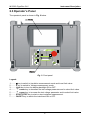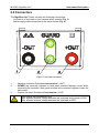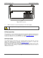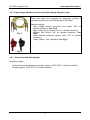
1
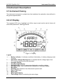
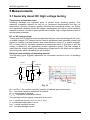
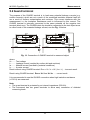
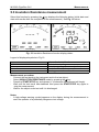
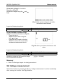
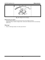
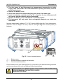
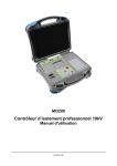
GigaOhm 5kV MI 3202 User Manual Version 1.5, Code No. 20 751 271 Distributor: Producer: METREL d.d. Ljubljanska 77 SI-1354 Horjul Tel.: +386 1 75 58 200 Fax: +386 1 75 49 226 E-mail: [email protected] http://www.metrel.si Mark on your equipment certifies that this equipment meets the requirements of the EU (European Union) concerning safety and electromagnetic compatibility regulations © 2007, 2010 Metrel No part of this publication may be reproduced or utilized in any form or by any means without permission in writing from METREL. 2 MI 3202 GigaOhm 5 kV Table of contents Table of contents 1 General introduction .......................................................................................... 4 1.1 Features ........................................................................................................4 1.2 Applied Standards .........................................................................................4 2 Instrument Description .......................................................................................5 2.1 Instrument Casing .........................................................................................5 2.2 LC Display .....................................................................................................5 2.3 Operator’s Panel ...........................................................................................6 2.4 Connectors ....................................................................................................7 2.5 Accessories ...................................................................................................8 2.6 Test leads......................................................................................................8 3 Warnings ............................................................................................................10 4 Performing measurements ...............................................................................12 4.1 Switching on the instrument ........................................................................12 5 Measurements....................................................................................................14 5.1 Generally about DC High voltage testing.....................................................14 5.2 Guard terminal.............................................................................................15 5.3 Insulation Resistance measurement ...........................................................16 5.4 Voltage measurement .................................................................................17 6 Maintenance .......................................................................................................19 6.1 Inspection ....................................................................................................19 6.2 Insertion and charging batteries for the first time.........................................19 6.3 Replacement and charging batteries...........................................................19 6.4 Cleaning ......................................................................................................21 6.5 Calibration ...................................................................................................21 6.6 Service ........................................................................................................21 7 Specifications ....................................................................................................22 7.1 Measurements.............................................................................................22 7.2 General specifications .................................................................................24 3 MI 3202 GigaOhm 5 kV General introduction 1 General introduction 1.1 Features The GigaOhm 5kV Tester is a portable battery / mains powered test instrument intended for simple testing of Insulation Resistance by using high test voltages of up to 5 kV. It operates on a SIMPLE and CLEAR basis. The instrument is designed and produced with the extensive knowledge and experience acquired through many years of dealing with similar test equipment. Available functions offered by the GigaOhm 5kV Tester: High Insulation Resistance measurement up to 1 T Programmable test voltage: 250 V, 500 V, 1 kV, 2.5 kV, 5 kV; Automatic discharge of tested object after measurement completion; Voltage and frequency measurement up to 600 V AC/DC. A segment LCD offers easy-to-read results and all associated parameters. Operation is simple and clear; the operator does not need any special training (except reading and understanding this Users Manual) to operate the instrument. 1.2 Applied Standards Instrument operation IEC / EN 61557-2 Electromagnetic compatibility (EMC) EN 61326 Class B Safety EN 61010-1 (instrument), EN 61010-031 (accessories) 4 MI 3202 GigaOhm 5 kV Instrument Description 2 Instrument Description 2.1 Instrument Casing The instrument is housed in a plastic box that maintains the protection class defined in the general specifications. 2.2 LC Display The segment LCD has a backlight and offers easy-to-read results and all shows all associated parameters. See Fig.1 below. Fig. 1. LC Display Legend: 1.......... Battery indicator. It indicates condition of the battery. In battery charging mode it flashes. 2.......... Hazardous Voltage Warning icon. It indicates that the voltage higher than 70 V may be present at the test terminals! 3.......... Analogue display. 4.......... Auxiliary digital display. 5.......... Auxiliary units. Units for parameters displayed on auxiliary display. 6.......... Analogue units. Units for parameters displayed on analogue display. 7.......... Bar graph. 8.......... Warning icon. Read the User Manual with special care! 9.......... Pass or Fail icon. 10........ Main units. 11........ Main digital display. 12........ Test voltage. Menu for selecting the test voltage. 5 MI 3202 GigaOhm 5 kV Instrument Description 2.3 Operator’s Panel The operator’s panel is shown in Fig. 2 below. Fig. 2. Front panel Legend: 1.......... key to switch to Insulation measurement mode and to set limit value. 2.......... V key to switch to Voltage measurement mode. 3.......... Light key to turn the display backlight ON or OFF. 4.......... cursor key to decrease the test voltage parameter and to select limit value. 5.......... 4 cursor key to increase the test voltage parameter and to select limit value. 6.......... START/STOP key to start or stop insulation measurement. 7.......... ON/OFF key to switch the instrument ON or OFF. 6 MI 3202 GigaOhm 5 kV Instrument Description 2.4 Connectors The GigaOhm 5 kV Tester contains the following connections: - Connection of test leads to four banana safety sockets (Fig. 3), - Mains supply cable connection to the mains socket (Fig. 4). Fig. 3. Test leads connector 1.......... Negative Insulation Resistance test terminal. (-OUT) 2.......... GUARD test terminals intended to lead away potential leakage current while measuring the Insulation. Both green sockets are connected together inside the instrument. 3.......... Positive Insulation Resistance test terminal (+OUT) Use original test accessories only! Max. allowed external voltage between test terminals and ground is 600V! Max. allowed external voltage between test terminals is 600V! 7 MI 3202 GigaOhm 5 kV Instrument Description Fig. 4. Mains connector 1.......... Mains connector to connect the instrument to the mains supply. Use original mains supply cable only! 2.5 Accessories The accessories consist of standard and optional accessories. Optional accessories can be delivered upon request. See attached list for standard configuration and options or contact your distributor or see the METREL home page: http://www.metrel.si. 2.6 Test leads The standard length of test leads is 2m, optional lengths are 8m and 15m. For more details see attached list for standard configuration and options or contact your distributor or see the METREL home page: http://www.metrel.si. All test leads are made of high voltage shielded cable, because shielded cable provides higher accuracy and immunity to disturbance of measurements that can occur in industrial environments 8 MI 3202 GigaOhm 5 kV Instrument Description 2.5.1. High voltage shielded test tips with High voltage alligators clips. Application notes: These test leads are designed for diagnostic testing of insulation and also for hand held testing of insulation. Fig. 5 Insulation ratings: - High voltage banana connector (red, black): 5kV d.c (double insulation). See Fig.5. - High voltage tip (red, black): 5kV d.c (double insulation). - Alligator (red, black): 5kV d.c (double insulation). See Fig.6. - Guard banana connector (green): 600V CAT IV (double insulation). - Cable (yellow): 12kV (shielded). See Fig.5. Fig. 6 2.6.1 Guard test lead with alligator Insulation ratings: - Guard test lead with banana connectors (green): 600V CAT IV (double insulation); Alligator (green): 600V CAT IV (double insulation). 9 MI 3202 GigaOhm 5 kV Warnings 3 Warnings In order to reach the highest level of operator’s safety while carrying out various measurements and tests using the GigaOhm 5kV Tester, as well as to ensure that the test equipment remains undamaged, it is necessary to consider the following warnings: MEANING OF SYMBOLS Symbol on the instrument means “Read the User Manual with special care!”. Symbol on the instrument means “Hazardous voltage higher than 70 V may be present at the test terminals!”. GENERAL PRECAUTIONS If the test equipment is used in a manner not specified in this Users Manual, the protection provided by the equipment may be impaired! Do not use the instrument and accessories, if any damage is noticed! Consider all generally known precautions in order to avoid risk of electric shock while dealing with hazardous voltages! Consider all generally known precautions in order to avoid the risk of electric shock while dealing with electric installations! Service intervention or recalibration procedure can be carried out only by a competent and authorized person! Only adequately trained and competent persons may operate the instrument. A segment LCD offers easy-to-read results and all associated parameters. Operation is simple and clear; the operator does not need any special training (except reading and understanding this Users Manual) to operate the instrument. BATTERIES Disconnect all test leads, main supply cable and switch the power off before opening the Battery cover! Use only NiMh rechargeable batteries (C size)! EXTERNAL VOLTAGES Do not connect the instrument to a mains voltage different from the one defined on the label adjacent to the mains connector, otherwise the instrument may be damaged. Do not connect test terminals to an external voltage higher than 600 V DC or AC (CAT IV environment) to prevent any damage to the test instrument! 10 MI 3202 GigaOhm 5 kV Warnings WORKING WITH THE INSTRUMENT Use only standard or optional test accessories supplied by your distributor! Equipment under test must be switched off (i.e. de-energized) before test leads are connected to the equipment. Do not touch any conductive parts of equipment under test during the test. Make sure that the tested object is disconnected (mains voltage disconnected) before starting the Insulation Resistance measurement! Do not touch the tested object whilst testing it, risk of electric shock! In case of a capacitive test object (long tested cable etc.), automatic discharge of the object may not be done immediately after finishing the measurement – “Please wait, discharging” message will be displayed. HANDLING WITH CAPACITIVE LOADS Note that 40 nF charged to 1 kV or 9 nF charged to 5 kV are hazardous live! Never touch the measured object during the testing until it is totally discharged. Maximum external voltage between any two leads is 600 V (CAT IV environment). 11 MI 3202 GigaOhm 5 kV Performing measurements 4 Performing measurements 4.1 Switching on the instrument Auto-calibration The instrument is switched ON by pressing the ON/OFF key. After turning on (Fig. 7), the instrument first executes the auto-calibration (Fig. 8). Note: If batteries are defective or missing and the instrument is powered from mains supply, the instrument could not be turn ON Measuring test leads have to be disconnected during auto-calibration. If not the autocalibration procedure could be false. After finishing the auto-calibration, the pass icon will appeared; the instrument goes to the Insulation Mode (Fig.9) and is prepared for normal operation. Auto-calibration prevents a reduction in accuracy when measuring very low currents. It compensates the effects caused by ageing, temperature and humidity changes etc. A new auto-calibration is recommended when the temperature changes by more than 5C. Fig. 7. First introduction Fig. 8. Auto-calibration state Fig. 9. Insulation Mode Note: x If the instrument detects incorrect an state during the auto-calibration, the fail icon will be displayed: Possible reasons for out of range conditions are excessive humidity, excessively high temperature, etc. In this case it is possible to perform measurements by press START/STOP button again but results could be out of technical specification. Mains powered instrument operation If you connect the instrument to the mains supply when the instrument is turned OFF, internal charger will begin to charge the batteries but instrument will be remain turned OFF. In upper left angle of LCD, flashing battery indicator will appear to indicate that the batteries are charging. 12 MI 3202 GigaOhm 5 kV Performing measurements Note: If batteries are defective or missing, the charger will not work. If you connect the instrument to the mains supply when instrument is turn ON, the instrument will automatically switch from the battery supply to the main supply. If the instrument is not in insulation measuring mode*, internal charger will begin to charge the batteries. In upper left angle of LCD, battery indicator will start to flash, indicating that the batteries are charging. Note: It is not recommended to connect or disconnect the instrument to mains supply while the instrument is in measuring mode*. *measuring mode When the instrument performing insulation measurements. Backlight operation (battery powered instrument) After turning the instrument ON the LCD backlight is automatically turned ON. It can be turned OFF and ON by simply clicking the LIGHT key. Backlight operation (mains powered instrument) After turning the instrument ON the LCD backlight is automatically turned OFF. It can be turned OFF and ON by simply clicking the LIGHT key. Off function The instrument can be switched OFF only by pressing the ON/OFF key. The auto-off function is not available to allow long-term measurements. 13 MI 3202 GigaOhm 5 kV Measurements 5 Measurements 5.1 Generally about DC High voltage testing The purpose of insulation tests Insulating materials are important parts of almost every electrical product. The material’s properties depend not only on its compound characteristics but also on temperature, pollution, moisture, ageing, electrical and mechanical stress, etc. Safety and operational reliability require the regular maintenance and testing of the insulation material to ensure it is kept in good operational condition. High voltage tests are used to test insulating materials. DC vs. AC testing voltage Testing with a DC voltage is widely accepted as being as useful as testing with AC and / or pulsed voltages. DC voltages can be used for breakdown tests especially where high capacitive leakage currents interfere with measurements using AC or pulsed voltages. DC is mostly used for insulation resistance measurement tests. In this type of test, the voltage is defined by the appropriate product application group. This test voltage is lower than the voltage used in the withstanding voltage test so the tests can be applied more frequently without stressing the test material. Electrical representation of insulating material The following figure (Fig.10) represents the equivalent electrical circuit of insulating material Itest + material surface Riss1 Cpi Riso Guard Ciso Itest IPI Rpi Riss2 ICiso - IRiso IRiss Fig. 10 Riss1 and Riss2 - the surface resistivity (position of optional guard connection) Riso – the actual insulation resistance of material Ciso – capacitance of material Cpi, Rpi - represents polarization effects. The right figure shows typical currents for that circuit. Itest = overall test current (Itest= IPI+ IRISO+ IRISS) IPI = polarization absorption current IRISO = actual insulation current IRISS = surface leakage current 14 MI 3202 GigaOhm 5 kV Measurements 5.2 Guard terminal The purpose of the GUARD terminal is to lead away potential leakage currents (e.g. surface currents), which are not a result of the measured insulation material itself but are a result of surface contamination and moisture. This current interferes with the measurement i.e. the Insulation Resistance result is influenced by this current. The GUARD terminal is internally connected to the same potential as the negative test terminal (black one). The GUARDs test clip should be connected to the test object so as to collect most of the unwanted leakage current, see the Fig. 11 below. IL IM IM IL +OUT -OUT Ut IA +OUT Ut A IA IL -OUT GUARD A Fig. 11. Connection of GUARD terminal to measured object where: Ut ........ Test voltage IL ......... Leakage current (resulted by surface dirt and moisture) IM ........ Material current (resulted by material conditions) IA ......... A-meter current Result without using GUARD terminal: RINS = Ut / IA = Ut / (IM + IL) …incorrect result. Result using GUARD terminal: RINS = Ut / IA = Ut / IM ……correct result. It is recommended to use the GUARD connection when high insulation resistance (>10G ) are measured. Note: The guard terminal is protected by an internal impedance (200 K). The instrument has two guard terminals to allow easy connection of shielded measuring leads. 15 MI 3202 GigaOhm 5 kV Measurements 5.3 Insulation Resistance measurement Select this function by pressing the key displays the following states (initial state and state with results after the completion of the measurement). See Fig. 12 below. Display with results Initial display Fig. 12. Insulation Resistance function display states Legend of displayed symbols in Fig 12: INSULATION RESISTANCE 250V 253 V 102 M Bar Name of selected function Selected test voltage Actual test voltage (measured value) Insulation Resistance – result Analog presentation of result Measurement procedure: - Connect the test leads to the instrument and to the test object. - Select INSULATION RESISTANCE mode by pressing the key. - Press the START/STOP key and release it, (continuous measurement will begin). - Wait until the test result has stabilized then press the START/STOP key again to stop the measurement. - Wait for the object under test until it is discharged. Notes: - A high-voltage warning symbol appears on the display during the measurement to warn the operator of a potentially dangerous test voltage. 16 MI 3202 GigaOhm 5 kV Measurements Set-up test voltage for Insulation Resistance (Fig.13): Adjust test voltage using the and keys. Fig. 13. Set-up test voltage in Insulation Resistance measurement Legend of displayed symbols: INSULATION RESISTANCE Unominal 250V Name of selected function Set test voltage Set-up Insulation resistance limit value for Insulation Resistance (Fig.13): - Press the key , - Adjust the limit value using the keys and , - Press the key again or the key START to return to into insulation resistance measurement menu. Fig. 13a. Set-up Insulation Resistance limit value Legend of displayed symbols: INSULATION RESISTANCE Resistance value 1 M Name of selected function Selected insulation resistance limit Insulation resistance limit selection range: No limit selected indication: [10 k .. 200 M] ––– Warning! Refer to Warnings chapter for safety precautions! 5.4 Voltage measurement Select this function by pressing the V key. Voltage measurement is active immediately after entering the function. See Fig. 14 below. 17 MI 3202 GigaOhm 5 kV Measurements Fig. 14. Voltage function display Measurement procedure: - Connect the test leads to the instrument and to the measured source. - Press the V key to select voltage mode, continuous measurement will automatically start to run. Warning! Refer to Warnings chapter for safety precautions! 18 MI 3202 GigaOhm 5 kV Maintenance 6 Maintenance 6.1 Inspection To maintain the operator’s safety and to ensure the reliability of the instrument it is advisable to inspect the instrument on a regular basis. Check that the instrument and its accessories are not damaged. If any defect is found please consult your service center, distributor or manufacturer. 6.2 Insertion and charging batteries for the first time Battery cells are stored in the bottom section of the instrument casing under the battery cover (see Fig. 15). When inserting batteries for the first time please note the following: Disconnect any measurement accessories or mains supply cable connected to the instrument before opening the battery cover to avoid electric shock. Remove the battery cover. Insert batteries correctly (see Fig. 15), otherwise the test instrument will not operate! Replace the battery cover and fixed the cover back in place. Connect the instrument to the mains power supply for 14 hours to fully charge batteries. (Typical charging current is 300 mA). When you charge the batteries for the first time, it normally takes about 3 charge and discharge cycles for the batteries to regain full capacity. 6.3 Replacement and charging batteries The instrument is designed to be power by rechargeable battery supported by mains supply. The LCD contains an indication of battery condition (upper left section of LCD). When the low-battery indication appears (Err) the batteries have to be recharged, connect the instrument to the mains power supply for 14 hours to recharge cells. Typical charging current is 300 mA. Note: Operator does not need to disconnect the instrument from mains supply after the full recharging period. The instrument can be connected permanently. Fully charged rechargeable batteries can supply the instrument for approx. 4 hours. (Continues testing at 5kV) If the batteries have been stored for a long time, it normally takes about 3 charge and discharge cycles for the batteries to regain full capacity. Battery cells are stored in the bottom section of the instrument casing under the battery cover (see Fig. 15). In case of defective batteries please note the following: 19 MI 3202 GigaOhm 5 kV Maintenance Turn the power off and disconnect any measurement accessories or mains supply cable connected to the instrument before opening the battery cover to avoid electric shock. Remove the battery cover. All six cells have to be replaced and they have to be of the same type. Insert the batteries correctly (see Fig. 15), otherwise the test instrument will not operate and the batteries may be discharged! Replace the battery cover and fixed the cover back in place. The Instrument will only work when rechargeable batteries are inside the instrument. Nominal power supply voltage is 7.2 V DC. Use six NiMH cells with C size (dimensions: diameter = 26 mm, height = 46 mm). See the next figure Fig.15 for correct polarity of batteries. Fig. 15. Correct inserted batteries 1.......... Battery cover. 2.......... Screw (unscrew to replace the batteries). 3.......... Correct inserted batteries. Ensure batteries are used and disposed of in accordance with Manufacturers guidelines and in accordance with Local and National Authority guidelines DISCONNECT ALL TEST LEADS AND SWITCH OFF INSTRUMENT BEFORE REMOVING THE BATTERY COVER! HAZARDUS VOLTAGE! 20 MI 3202 GigaOhm 5 kV Maintenance 6.4 Cleaning Use a soft cloth, slightly moistened with soapy water or spirit to clean the surface of the instrument and leave the instrument to dry totally before using it. Notes! Do not use liquids based on petrol or hydrocarbons! Do not spill cleaning liquid over the instrument! 6.5 Calibration It is essential that all measurement instruments be regularly calibrated. For occasional daily use we recommend an annual calibration to be carried out. When the instrument is used continuously every day, we recommend calibrating the instrument every six months. 6.6 Service For repairing under or out of warranty period contact your distributor for further information. 21 MI 3202 GigaOhm 5 kV Specifications 7 Specifications 7.1 Measurements Note: All data regarding accuracy are given for nominal (reference) environment condition. Insulation resistance Nominal test voltage: Current capability of test generator: Short-circuit test current: Automatic discharge of tested object: 250 V, 500 V, 1 kV, 2.5 kV, 5 kV >1 mA 5 mA. yes Measuring range Riso: 0.12 M up to 999 G*) Display range Riso Resolution 5 999 k 1 k 1.00 9.99 M 10 k 10.0 99.9 M 100 k 100 999 M 1 M 1.00 9.99 G 10 M 10.0 99.9 G 100 M 100 999 G 1 G Accuracy (5 % of reading + 3 digits) (10 % of reading + 3 digits) * Full-scale value of insulation resistance is defined according the following equation: RFS = 1G * Utest[V] (if Utest > 1kV then RFS = 1T For insulation resistance value under 5 kthe instrument displays value 0 DC test voltage: Voltage value: Accuracy: Output power: 250V, 500V, 1kV, 2,5kV, 5kV. -0 / +10 % + 20 V. 5 W max. Display range test voltage (V) 0 1999V 2.00k 5.50k Resolution 1V 10 V 22 Accuracy (3 % of reading + 3 V) MI 3202 GigaOhm 5 kV Specifications Generator Capability vs Resistance 6 5 [ kV ] 4 3 2 1 0 0,1 1 10 100 [ M ] Utest=5kV Voltage Voltage AC or DC Display range External Voltage (V) 0 600 Resolution 1V Accuracy (3 % of reading + 4 V) Frequency of external voltage Display range (Hz) 0 and 45 65 Resolution 0.1 Hz Accuracy 0.2 Hz Note: - for frequency between 0 and 45 Hz frequency result is shown as - for frequency over 65 Hz frequency result is shown as - for voltages under 10V frequency result is shown as Input resistance: 3 M 10 % 23 ___ ___ ___ MI 3202 GigaOhm 5 kV Specifications 7.2 General specifications Battery power supply ..................................... 7.2 V DC (6 × 1.2 V NiMHC size) Mains power supply ....................................... 90-260 V AC, 45-65 Hz, 40 VA Over-voltage category ................................... 300 V CAT III Protection classification ................................. double insulation Measurement category .................................. 600 V CAT IV Pollution degree............................................. 2 Degree of protection ...................................... IP 40 with case closed Dimensions (w × h × d).................................. 31 cm x 13 cm x 25 cm Weight (without accessories, with batteries).. 3 kg Visual and sound warnings............................ yes Display........................................................... LCD segments and analogue scale with backlight ENVIRONMENT CONDITIONS Working temperature range ........................... -10 50 °C Nominal (reference) temperature range......... 10 30 °C Storage temperature range............................ -20 +70 C. Maximum humidity ........................................ 90% RH (0 40 °C) non-condensing Nominal (reference) humidity range............... 40 60 % RH Nominal altitude ............................................. up to 2000m AUTO-CALIBRATION Auto-calibration of measuring system............ every time after turning power on CONNECTING SYSTEM Two safety banana sockets ........................... +OUT, -OUT (5kV CAT I, Double) Two GUARD. banana sockets ....................... GUARD (600V CAT IV, Double) Guard resistance ........................................... 200 k 10 % DISCHARGING Every time after measurement completion. Discharging resistance: ................................. 300 k 10 % 24