1
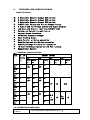
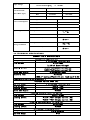
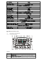
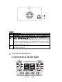
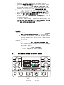
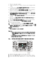
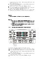
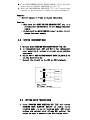
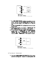
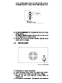
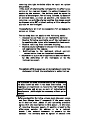
CONTENTS:
1. SAFETY PRECAUTION AND PROCEDURES…………………………3
1.1
BEFORE USE…………………………………………………….. 4
1.2
DURING USE…………………………………………………….. 5
1.3
AFTER USE………………………………………………………. 5
2. GENERAL………………………………………………………………… 6
3. FEATURES AND SPECIFICATIONS……………………………………. 6
3.1
MAIN FEATURES……………………………………………….. 6
3.2
GENERAL SPECIFICATIONS………………………………… 7
3.3
OPERATION CONDITIONS…………………………………… 7
3.4
TECHINICAL SPECIFICATIONS……………………………….. 8
4. OPERATING INSTRUCTIONS………………………………………… 10
4.1.
INSTRUMENT DESCRIPTION………………………………….10
4.1.1
FRONT PANEL DESCRIPTION………………………………… 10
4.1.2
REAR PANEL DESCRIPTION………………………………… 13
5. POWER SUPPLY DESCRIPTION…………………………………………14
5.1.
SETTING THE OUTPUT VOLTAGE…………………………… 14.
5.2.
SETTING THE OUTPUT CURRENT…………………………….16
5.3
FIXED 5V/1A OUTPUT (FOR GRADE C MODEL ONL Y)…… 18
6. FUSE REPLACEMENT…………………………………………………… 24
7. PACKAGE………………………………………………………………… 25
8. TROUBLESHOOTING…………………………………………………… 26
9. SERVICE……………………………………………………………………26
9.1. WARRANTY CONDITIONS……………………………………… 26
9.2. SERVICING………………………………………………………… 27
1.
SAFETY PRECAUTION AND PROCEDURES
The instrument is designed and tested in accordance with EN publication
61558-2-6:11.97.The instrument has been tested in accordance to the following
EC Directives(EMC):
a. EN61204-3:12.2000
b. EN61000-3-2:04.95+A1:1998+A2:1998+A14:2000
c. EN61000-3-3:01.95
The instrument complies with the requirements of the European Council
Directive 89/336/EEC(EMC Directive)and 73/23/EEC(Low Voltage Directive).
To ensure that the instrument is used safety. follow all safety and operating
Instructions in this manual . If the instrument is not used as described in this
manual, the safety features might be impaired
WARNING
Non compliance with the warnings and/or the instructions for use may damage the
instrument and/or its components or injure the operator.
Take extreme care under the following conditions when using the instrument:
● For your own safety and that of the instrument ,you must follow the
procedure described in this instruction manual.
● Do not use this instrument in a location where there is explosive gas in the
vicinity. The use of this instrument in a location where there is explosive
gas could result in explosion.
● If there is any smoke, abnormal odor , or abnormal sound coming from
this instrument, immediately switch off the power and disconnect the
power cord. Continuous using of this instrument under these conditions
could result in electrical shock or fire . After disconnecting the power cord,
contact the service offices for repair by the user is dangerous and should be
strictly avoided.
● Take care not to allow water to get into this instrument .The use of this
instrument in a wet state could result in electrical shock or fire. If water or
other foreign matter has penetrated this instrument , switch the power
off ,then remove the power card and call for repair.
● Do not place this instrument on an unstable or slanting surface. The
dropping or turning over this instrument could result in electrical shock,
injury or fire. If this instrument has been dropped or its cover has
damaged, switch the power off, remove the power cord and call for repair.
● Do not allow any foreign matter such as metal or inflammable substance to
get into the instrument via the air holes . The penetration of any foreign
matter from the ventilation holes could result in fire . electrical shock ,or
power failure.
● Use this instrument with the rated AC power sources . Use of this
instrument with a voltage other than specified could result in electrical
shock ,fire or power failure. The usable power voltage range is marked on
the rear panel.
● Do not remove either the cover or panel.
● Do not modify this instrument.
● Avoid use of damaged cables.
1.1.
1.
2.
3.
BEFORE USE
Make sure the POWER switch is pressed and connect the power cord to
the power supply.
Our PSM series is a dynamic type power supply . The user can ground the
output terminal by using the ground plate between the ground (GND)and
cathode(-)or the ground(GND)and anode(+).
To set the constant voltage output: Power on the power supply . Adjust the
VOLTAGE tune knob for adjustment . Once the voltage or current value is
reached, the desired value will appear on the Display Panel.
1.2 DURING USE
1 . Ensure the voltage and current is set to zero ,prevent a undesired output
for damaging the circuit .
2 . The supplied voltage should be within 110V AC or 220V AC±10%(50Hz)
and the system is capable for supplying the maximum power consumption
as indicated on section 3.3.
3. keep a distance at least greater than 10cm between the power supply and
other things for airy reason when usage . Do not place this power supply
in a hot , dusty . wet, corrosive gas stage or near the poison substance.
4. The power supply needed warm up for 30 minutes , to meet the
specification. Section 3.4.
5. keep hands and face away from the ventilation fan.
6. Do not touch the rear panel during operation.
1.3. AFTER USE
1. Once the operation completed, remove all connections from the power
supply ,especially the power source.
2. Wait for the power supply to cool down.
3. Store in a dry , well air and non-dusty environment.
2.
GENERAL
PSM series is a high performance and precision multi channels DC regulated
power supply up to 4-channel outputs. Our PSM series has constant voltage
mode , constant current mode ,auto current cut off protection function,
overload protection and auto tracking mode .In auto tracking mode ,PSM
series can auto connect CH1 and CH2 output either in parallel or in series
intermally to provide double current or voltage output.
Our PSM4 series provide 4 channels adjustable outputs . Our PSM3 series
provide 2 channels adjustable output and one fixed 5v/1a output. Our PSM2
series provide 2 channels adjustable output .All adjustable outputs voltage and
current value can be adjusted linearly.
With the extract stability and enhanced responsibility ,this power supply is
suitable for bench , laboratory ,university, high school , and enterprise use or
where needed a high performance and precision regulated DC power supply.
3.
FEATURES AND SPECIFICATIONS
MAIN FEATURES
●. 2 Adjustable Channels Output (RS2 series)
●. 3 Adjustable Channels Output (RS3 series)
●
4 Adjustable Channels Output (RS4 series)
●
0-30V Linear Voltage and Current Output Display
●
4 Sets of LED for Voltage and Current Output Display
●
Low Noise and Ripple ; Less than 1mV(5Hz-1mHz)
●
Voltage and Current Pre-set Feature
●
Current Output Protection
●
CV/CC Mode Automatic Changer
●
Auto Tracking Output
●
Auto Parallel or Series connection
●
Doubling Current with Series connection
●
Doubling Voltage with Parallel connection
●
16 Hours Continuous Operation with Full Loading
●
Rugged Metal Cabinet
3.2. GENERAL SPECIFICATIONS
Mode No. of
CHANNEL OUTPUT
Channe CH1
l
CH2
CH3
ls
Volta Curre
Volta Curre Volta Curre
ge
RS13
22
RS13
23
RS13
25
RS13
32
RS13
33
RS13
35
RS13
42
RS13
43
RS13
45
2
nt
2
3A
2
5A
5A
2A
3
3A
0 ~ 2A
30V
3A
3
5A
5A
2A
4
0~
30v
2A
ge
0 ~ 2A
30V
3A
3
0~
30v
nt
0~
30v
4
3A
0 ~ 2A
30V
3A
4
5A
5A
ge
nt
CH4
Volta
Ccurre
ge
nt
N/A
5V
1A
2.2
~
5.2V
1A
N/A
8~
15V
3.3. OPERATION CONDITIONS
Environmental
Condition
Operating altitude <2000m.pollution degree Ⅱ
1A
Input Voltage
110VAC/220VAC±10﹪
at 50/60Hz
220V
Fuse Protection:
(Fu se Blow Type)
Power Consumption:
Operating Condition
110V
RS2
T2A/250V
T6A/250V
RS3
T3A/250V
T6A/250V
RS4
T4A/250V
T6A/250V
5A output model
600 W
3A output model
380 W
2A output model
260 W
Temperature
Relative Humidity
Temperature
Storage Condition
Relative Humidity
0~40℃
≦80﹪RH
﹣1℃~70℃
≦80﹪RH
3.4. TECHINICAL SPECIFICATIONS
Channel 1and 2 Characteristic
Constant Voltage Mode(CV)
Voltage Range
0 to maximum rated current
Line Effect
≤1X10¯4+3mV
(±10% of Rated Voltage)
Loading Effect
≤1X10¯4+3mV(output current≤3A)
≤2X10¯4+3mV(output current≥3A)
Noise and Ripple
≤1mVrms(5Hz-1MHz)
Recovery Time
≤100usec
(50% of loading effect with min. loading of 0.5A)
Temperature Coefficient ≤300ppm/℃
Constant Current Mode (CC)
Current Range
0 to maximum rated current
Line Effect
≤2X10‐3+3mA
Loading Effect
≤2X10‐3+3mA
Noise and Ripple
≤3mAms
Tracking Characteristic (in Series)
Line Effect
≤1*10‐4+3mV
‐4
Loading Effect
≤1X10 +3mV (Output current ≤3A)
4
≤2X10‐ +3mV (Output current ≥3A)
Tracking Characteristic (in Parallel)
Line Effect
≤1X10⁴+5mV
Loading Effect
≤300mV
RS4 Channel 3 Characteristic
Voltage Range
2.2-5.2V(±8%)
Current Range
0-1A
Line Effect
Loading Effect
Noise and Ripple
≤5mV
≤15mV
≤2mVrms(5Hz-1MHz)
RS4 Channel 4 Characteristic
Voltage Range
8-15V (±8%)
Current Range
0-1A
Line Effect
≤5mV
Loading Effect
≤15mV
Noise and Ripple
≤2mVrms(5Hz-1MHz)
PSM3 Channel 3 Characteristic
Voltage Range
5.0V (±8%)
Current Range
Fixed 1A
Line Effect
≤5mV
Loading Effect
≤15mV
Noise and Ripple
≤2mVrms(5Hz-1MHz)
Display Accuracy
Digital Display
3 Digital Display(±0.5%+2d)
Insulation
Chassis and Terminal
≤20MΩ,at DC500V
Chassis and Power Cord
≤30MΩ,at DC500V
Mechanical Specification
Weight (kg):
7.5 approximately
Dimension (mm):
255X150X305
4. OPERATING INSTRUCTIONS
4.1.
4.1.1.
INSTRUMENT DESCRIPTION
Front panel description
GND
POWER
Legend:
ltem
1
2
Description
POWER SWITCH: Press it to power on/off the power supply
CH2/CH4 DISPLAY SWITCH: PRESS it to select display CH4
Voltage/current value or release to release to select display
CH2 voltage/current value.
3
CH4 VOLTAGE tune knob (for PSM4 model):turn clockwise for
increasing the voltage value; turn anti-clockwise for
decreasing the voltage value.
4
CH2 CURRENT tune knob: Turn clockwise for increasing the current
value; turn anti-clockwise for decreasing the voltage value.
5
CH2 VOLTAGE tune knob: Turn clockwise for increasing the voltage
value; turn anti-clockwise for decreasing the voltage value.
6
CH2 CV/CC(CONSTANT VOLTAGE/CURRENT MODE)
INDICATOR: When CH2 is at the constant voltage mode, this LED
light will be on as green colour. When CH2 is at the current
mode and in Parallel Tracking Mode ,this LED light will be on
as red colour.
7
CH4 OVERLOAD INDICATOR (for psm4 model):When CH4is at the
constant current mode this LED light will be on.
8
AUTO CURRENT CUT OFF PROTECTION KEY: After power ON .the power
supply will at protection state (no voltage output at all
terminals and OUTPUT indicator[9] is OFF);however, the voltage
DISPLAY. Panel[10,11]will still show the pre-set voltage
value .When the Auto Current Cut off protection key is pressed,
all terminals will output the voltage as indicated on the
voltage display panel and the OUTPUT indicator[9]is ON. repress
the key to cut off the output again .After cut off, it takes
3 seconds interval to return normal.
9
10
OUTPUT INDICATOR: see[8]
11
CH1/CH3 VOLTAGE DISPLAY PANEL: This display will indicate CH1
or CH3 voltage value that will be applied to the circuit
12
TRACKING MODE SELECTION KEY: this key is operated with key
[5],to select INDEPENDENT MODE, SERIES TRACKING MODE and
PARALLEL TRACKING MODE for CH1and CH2 output.
a) To select INDEPENDENT MODE: Release these two keys;CH1and
CH2 will operate separately.
b) To select SERIES TRACKING MODE : press Key[12] and release
key[15],CH2 output voltage will be followed by CH1,connect
the circuit to CH1 “+” terminal and CH2 “-“terminal to get
double rated voltage output.
c) To select PARALLEL TRACKING MODE : Press both Key[12] and
key[15],CH2 output voltage and current will be followed by
CH1,parallel connect the circuit to CH1 output will get 0-30v
and double rated current output.
13
CH2/CH4 CURRENT DISPLAY PANEL: This display will indicate CH2
or CH4 current value that will be applied to the circuit
14
CH1/CH3 CURRENT DISPLAY PANEL: This display will indicate CH1
or CH3 current value that will be applied to the circuit
15
16
TRACKING MODE SELECTION KEY: see[12]
CH2/CH4 VOLTAGE DISPLAY PANEL: This display will indicate CH2
or CH4 voltage value that will be applied to the circuit
CH3 OVERLOAD INDICATOR (for PSM4 model): When CH3 is at the
constant current mode this LED light will be on.
17
CH1 CV/CC(CONSTANT VOLTAGE/CURRENT MODE)
INDICATOR: When CH1 is at the constant voltage mode, this LED
light will be on as green colour. When CH1 is at the current
mode and in Parallel Tracking Mode, this LED light will be on
as red colour.
18
CH2 VOLTAGE tune knob: Turn clockwise for increasing the voltage
value; turn anti-clockwise for decreasing the voltage value.
When in SERIES/PARALLEL TRACKING MODE, use this knob to adjust
CH2 voltage.
19
CH1 CURRENT tune knob: Turn clockwise for increasing the current
value; turn anti-clockwise for decreasing the current value.
When in SERIES/PARALLEL TRACKING MODE, use this knob to adjust
CH2 current.
20
CH3 VOLTAGE tune knob (for PSM4 model): Turn clockwise for
increasing the voltage value; turn anti-clockwise for
decreasing the voltage value.
21
CH1/CH3 DISPLAY SWITCH: PRESS it to select display CH3
Voltage/current value or release to select display CH1
voltage/current value.
22
CH3 “+”TERMINAL: Positive terminal of 2.2-5.2v
adjustable output (for PSM4 model) or fixed 5v output (for
PSM3 model).
23
CH3 “-” TERMINAL: Negative terminal of 2.2-5.2v
adjustable output (for PSM4 model) or fixed 5v output (for
PSM3 model).
24
25
26
27
28
29
30
4.1.2
CH1 “+”TERMINAL: Positive terminal of 0-30v adjustable
output.
CH1 “-”TERMINAL: Negative terminal of 0-30v adjustable
output.
GND grounding terminal: This terminal is connecting to
the casing and the Earth.
CH2 “+”TERMINAL: Positive terminal of 0-30v adjustable
output.
CH2 “-”TERMINAL: Negative terminal of 0-30v adjustable
output.
CH4 “+”TERMINAL: Positive terminal of 8-15v adjustable
output. (for PSM4 model).
CH4 “-”TERMINAL: Negative terminal of 8-15v adjustable
output. (for PSM4 model).
Rear panel description
Legend:
ITEMS Description
31
FUSE SOCKET: Use suitable fuse which is stated in Section3.3
32
POWER INPUT SOCKET :Input AC220V/AC110V ±10%50/60Hz
33
INPUT VOLTAGE SELECTOR :For 110V AC power system, please
switch the INPUT VOLTAGE SELECTOR switch to the top for 110v
AC power system selection. For 220V AC power system, please
switch the INPUT VOLTAGE SELECTOR switch to the top for 220v
AC power system selection.
34
VENTILATION FAN: This fan is used to exhaust heat air from
internal heat sink.
5.
POWER SUPPLY DESCRIPTION
5.1 SETTING THE CH1 AND CH2 OUTPUT VOLTAGE
MAX
MIN
MIN
MAX
-
+
Connect to
the circoit
-
+
Connect to
the circoit
1. Connect the power supply to the power source.
2. Press the POWER SWITCH [1] to turn on the power supply.
3. To setting CH1,use the CH1 VOLTAGE TUNE KNOB [18] to
adjust CH1 voltage to give a desired output voltage.
4. Connect the circuit to the TERMINALS [24,25]
5. Press AUTO CURRENT CUT OFF PROTECTION KEY [8] to
activate output and the OUTPUT INDICATOR [9] will on.
6. When the CH1 CV/CC INDICATOR [17] is in red colour ,
adjust the CH1 CURRENT TUNE KNOB[19] to give a
suitable current.
7. To setting CH2 voltage , repeat the above steps ,use
CH2 VOLTAGE TUNE KNOB [5],short MAIN TERMINAL [26,27]
and CH2 CV/CC INDICATOR [6] instead.
Remarks:
1. If CH2 cannot be adjusted , check the TRACKING
MODE SELECTION KEY [12,15] is not pressed.
2. If want to preset a desired current output
before connecting to the circuit , read Section
5.2 first.
Caution:
· Make sure the INPUT VOLTAGE SELECTOR [33]set
to a correct position Otherwise ,it will damage
the power supply.
· Do not short the MAIN TERMINALS over 1 minute;
it will damage the power supply.
5.2.
SETTING THE CH1 OR CH2 OUTPUT CURRENT
MAX
MIN
MIN
MAX
-
+
Connect to
the circoit
-
+
Connect to
the circoit
1. Turn to the power supply
2. Refer to Section 5.1 step 1-4 to give the voltage around
2-5V
3. For CH1,turn the CH1 CURRENT TUNE KNOB [19] anticlockwise
reach the minimum current value.
4. Short the + and the - MAIN TERMINAL [24,25] with a conductor
2
which is cross section area not less than 0.5mm .
5. Ensure the output indicator is on. Otherwise , press the
AUTO CURRENT CUT OFF PROTECTION KEY [8].Then the CH1 CV/CC
INDICATOR [17] will turn to red colour.
6. Adjust the CH1 CURRENT KNOB [19] to give a desired output
current.
7. Repress the AUTO CURRENT CUT OFF PROTECTION KEY [8] to
Cut off the output.
8. Then the CH1 CV/CC INDICATOR[17] will turn to green colour.
9. Remove the conductor the MAIN TERMINA [24,25]
10.Set to desired voltage.
11.
Connect the circuit to the MAIN TERMINA [24,25]
12.
To setting CH2 current ,repeat the above steps ,use CH2
CURRENT TUNE KNOB [4],short MAIN TERMINAL [26,27] and CH2
CV/CC INDICATOR [6] instead.
Remarks:
· The conductor is not provided
Caution:
· Ensure the current is set to zero before shorting the
MAIN TERMINALS. Otherwise it will damage the power
supply.
· Do not short the MAIN TERMINALS over 1 minute; it will
damage the power supply.
5.3.
SETTING CH3 VOLTAGE OUTPUT (FOR RS3 AND RS4 ONLY)
MIN
-
MAX
+
Connect to
the circoit
1. Connect the power supply to the power source.
2. Press the POWER SWITCH [1] to turn on the power supply
3. Press CH1/CH3 DISPLAY SWITCH [21] to select display CH3
4.
5.
6.
7.
voltage and current value . When display CH3 value ,the
“CH3” icon will on .
Use the CH3 VOLTAGE KNOB [20] to adjust CH3 voltage to give
a desired output voltage.
Connect the circuit to the CH3 TERMINAL [22,23].
Press AUTO CURRENT CUT OFF PROTECTION KEY [8] to activate
output and the OUTPUT INDICATOR [9] will on.
When the CH3 OVERLOAD INDICATOR [16] is on ,remove some
loading on the terminal to reduce current consumption.
Remarks:
· Current output is fixed to 1A,not adjustable.
Caution:
· Make sure the INPUT VOLTAGE SELECTOR [33] set to a
correct position Otherwise ,it will damage the power
supply.
· Do not short the MAIN TERMINALS over 1 minute; it will
damage the power supply.
5.4.
MIN
SETTING CH4 VOLTAGE OUTPUT (FOR PSM4 ONLY)
MAX
-
+
Connect to
the circoit
1. Connect the power supply to the power source.
2. Press the POWER SWITCH [1] to turn on the power supply
3. Press CH2/CH4 DISPLAY SWITCH [2] to select display CH4
voltage and current value . When display CH4 value ,the
“CH4” icon will on .
4. Use the CH4 VOLTAGE KNOB [3] to adjust CH4 voltage to give
a desired output voltage.
5. Connect the circuit to the CH4 TERMINAL [29,30].
6. Press AUTO CURRENT CUT OFF PROTECTION KEY [8] to activate
output and the OUTPUT INDICATOR [9] will on.
7. When the CH4 OVERLOAD INDICATOR [7] is on ,remove some
loading on the terminal to reduce current consumption.
Remarks:
· Current output is fixed to 1A,not adjustable.
Caution:
· Make sure the INPUT VOLTAGE SELECTOR [33] set to a
correct position Otherwise ,it will damage the power
supply.
· Do not short the MAIN TERMINALS over 1 minute; it will
damage the power supply.
5.5.
SETTING INDEPENDENT MODE
1. Release both TRACKING MODE SLECTION KEY [12,15].
2. In independent mode ,CH1 and CH2 is two independent
power supply unit ,voltage or current can be adjusted
separately.
3. Adjust CH1 or CH2 VOLTAGE/CURRENT KNOB [19,20/4,5] to
set the desired value.
4. Connect the circuit to the CH1 or CH2 terminals.
Illustration of independent mode
5.6.
SETTING SERIES TRACKING MODE
1. Press TRACKING MODE SLECTION KEY [12] and release
TRACKING MODE SLECTION KEY[15] to enable series
tracking mode .In series tracking mode ,CH2 output
voltage and current value follows CH1 setting. The
output voltage is double to the CH1 display value.
Illustration of series tracking mode
2. Turn CH2 CURRENT KNOB[4] clockwise to maximum current
output, and then use CH1 CURRENT KNOB[19] adjust the
desired current output value.(Reference to Section
5.2)
3. Use CH1 VOLTAGE KNOB [18] to adjust the desired voltage
output value.
4. Connect the circuit to the CH1 “+”TERMINAL[24] and
CH2“-”TERMINAL[28] to get double voltage output.
5. For the bi-polar DC power supply with common ground,
connect CH2 “+” TERMINAL[27] to “GND” GROUNDING
TERMINAL [26]. CH1 “+”TERMINAL[24] is the positive
output and CH2 “-”TERMINAL[28] is the negative output.
Illustration of Bi-Polar Tracking Mode
SETTING PARALLEL TRACKING MODE
1. Press both TRACKING MODE SLECTION KEY[12,15] to enable
parallel tracking mode .In parallel tracking mode ,CH2
output voltage and current value follows CH1 setting.
The output current is double to the CH1 display value.
Illustration of Parallel Tracking Mode
2. Use CH1 VOLTAGE KNOB [18] to adjust the desired voltage
output value.
3. CH1 CURRENT KNOB[19] adjust the desired current output
value.(Reference to Section 5.2)
4. Connect the circuit to the CH1 TERMINAL [24,25] to get
double current output.
5.8
FUSE REPLACEMENT
1. Disconnect all power connection.
2. Locate the fuse socket at the rear panel power socket.
3. Pull out the fuse socket from the power socket.
Replace the fuse with identical rating .Refer to
section 3.3
4. Reinstate the fuse socket. (Re-push the fuse socket to
the power socket.
Caution:
· Ensure no power is connected to the power supply ;
otherwise ,electrical shock may occur.
· Do not over push the fuse socket ,or the fuse socket
may be damaged.
6.
1.
2.
3.
4.
PACKAGE
Power supply
power cord
Instruction manual
Main connection cable
RS4:4 cables
RS4:3 cables
RS4:2 cables
7. TROUBLESHOOTNG
Problem
Solution
The
power 1. Ensure the power source or power cord is working
supply
cannot
properly
start
up
(NO 2. Check the fuse .if the fuse broken ,disconnect
DISPLAY)
from the power source then replace with
identical rated fuse.
While operating This power supply is current protected. The
in the CV mode, desired current range is under the circuit gain;
the
voltage therefore ,the power supply is switched to CC
suddenly
drop mode ,Adjust the current knob clockwise to
down and the CC increase the current range.
indicator turns
The power supply 1. The power supply needs at least 30minutes to
output unstable.
warm up and reach the specification.
2. The power source (voltage)is under the minimum
requirement.
If the above solution cannot solve the problem ,please contact
the local dealer ,distributor or the manufacturer listed at the
back.
8. SERVICE
WARRANTY CONDITIONS
This instrument is guaranteed against any material fault or
manufacturer’s defect ,in accordance with the general
conditions of sale. During the warranty period (one
year).faulty parts may be replaced ,with the manufacturer
reserving the right to decide either to repair or replace
the product.
In the event of returning the instrument to the after-sales
service or to a regional branch ,the outward transport is
payable by the customer .The delivery must be agreed in
advance with consignee .For delivery indicate ,by means of
an enclosed note ,as clear as possible ,the reasons for
returning .use only the original packing. Any damage caused
by shipment using NOT original packing will be charged in
any case to the consignor.
The manufacturer will not be responsible for any damage to
persons or things.
The warranty does not apply to the following cases:
·. Accessories and fuse are not included in warranty.
· Repairs following unsuitable use of the instrument or
by combining the latter with incompatible instrument.
· Repairs resulting from incorrect shipping.
· Repairs resulting from servicing carried out by a person
not approved by the company.
· Modifications to the instrument without explicit
authorization from our technical department.
· Adaptation to a particular application not provided for
by the definition of the instrument or by the
instruction manual.
The contents of this manual may not be reproduced in any from
whatsoever without the manufacturer’s authorization.
This product has been patented/pending to be patented
in many countries that it has been distributed .The
logotypes are registered .we reserve the right to modify
specifications and prices as part of technological
developments ,which might be necessary without prior
notice.
SERVICING
Before contact for Servicing ,please check the power source
and fuse (change them if necessary).if the power supply
still does not work ,check if your operating procedure
agrees with the description in this manual .in the event
of returning the power supply ,it must be re-sent to the
after-sales service (at address or to a regional
branch ),the outward transport is payable by the
customer .the delivery must be agreed in advance with
consignee .For delivery indicate the reasons for returning
it .(By means of an enclosed note, as clear as possible)
use only the original packing .Any damage caused by delivery
with NO original packing will be charged in any case to the
consignor.