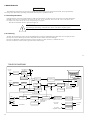
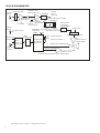
1
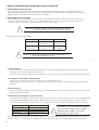
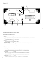
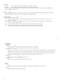
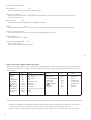
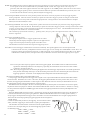
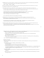
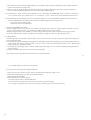
OSCILLOSCOPE
USER MANUAL
PAGE
CONTENTS
1.GENERAL ┈┈ ┈ ┈ ┈ ┈ ┈ ┈ ┈ ┈┈ ┈ ┈ ┈ ┈ ┈ ┈ ┈ ┈ ┈ ┈ ┈ ┈ ┈ ┈ ┈ ┈ ┈┈ ┈ ┈ ┈ ┈ ┈ ┈ ┈ ┈ ┈ ┈ ┈ ┈ ┈ ┈ ┈ 4
1.1Description┈ ┈ ┈ ┈ ┈ ┈ ┈ ┈ ┈ ┈ ┈ ┈ ┈ ┈ ┈ ┈ ┈ ┈ ┈ ┈ ┈ ┈ ┈ ┈ ┈ ┈ ┈┈ ┈ ┈ ┈ ┈ ┈ ┈ ┈ ┈┈ ┈ ┈ ┈ ┈ ┈ ┈ 4
1.2Features ┈ ┈ ┈ ┈ ┈ ┈ ┈ ┈ ┈ ┈┈ ┈ ┈ ┈ ┈ ┈ ┈ ┈ ┈ ┈ ┈ ┈ ┈ ┈ ┈ ┈ ┈ ┈┈ ┈ ┈ ┈ ┈ ┈ ┈ ┈ ┈ ┈ ┈ ┈ ┈ ┈ ┈ ┈ 4
2.TECHNICAL SPECIFICATIONS ┈ ┈ ┈ ┈ ┈ ┈ ┈ ┈ ┈ ┈ ┈ ┈ ┈ ┈ ┈ ┈ ┈ ┈ ┈ ┈ ┈ ┈ ┈ ┈ ┈ ┈ ┈ ┈ ┈ ┈┈ ┈ ┈ ┈ ┈ 5
2.1 Specifications part one: Digital Storage Oscilloscope ┈ ┈ ┈┈ ┈ ┈ ┈ ┈ ┈ ┈ ┈ ┈ ┈ ┈ ┈ ┈ ┈ ┈ ┈ ┈ ┈ ┈ ┈ ┈ ┈ ┈ 5
2.2 Specifications part two: Analog Real Time ┈ ┈ ┈ ┈ ┈ ┈ ┈ ┈ ┈ ┈ ┈ ┈ ┈ ┈ ┈ ┈ ┈ ┈ ┈ ┈ ┈ ┈ ┈ ┈ ┈ ┈ ┈ ┈ ┈ ┈ 6
3.PRECAUTIONS BEFORE OPERATING THE OSCILLOSCOPE ┈ ┈ ┈ ┈ ┈ ┈ ┈ ┈ ┈ ┈ ┈ ┈ ┈ ┈ ┈ ┈ ┈ ┈ ┈ ┈ ┈ ┈ ┈ 9
3.l Unpacking the Oscilloscope ┈ ┈ ┈ ┈ ┈ ┈ ┈ ┈ ┈ ┈ ┈ ┈ ┈ ┈ ┈ ┈ ┈ ┈ ┈ ┈ ┈ ┈ ┈ ┈ ┈ ┈ ┈ ┈ ┈ ┈ ┈ ┈ ┈ ┈ ┈ ┈ 9
3 2 Checking the Line Voltage ┈ ┈ ┈ ┈ ┈ ┈ ┈ ┈ ┈ ┈ ┈ ┈ ┈ ┈ ┈ ┈ ┈ ┈ ┈ ┈ ┈ ┈ ┈ ┈ ┈ ┈ ┈ ┈ ┈ ┈ ┈ ┈ ┈ ┈ ┈ ┈ 9
3.3 Environment┈ ┈ ┈┈ ┈ ┈ ┈ ┈ ┈ ┈ ┈ ┈ ┈ ┈ ┈ ┈ ┈ ┈ ┈ ┈ ┈┈ ┈ ┈ ┈ ┈ ┈ ┈ ┈ ┈┈ ┈ ┈ ┈ ┈ ┈ ┈ ┈ ┈ ┈ ┈ ┈ 10
3.4 Equipment Installation and Operation ┈ ┈ ┈ ┈┈ ┈ ┈ ┈ ┈ ┈ ┈ ┈ ┈┈ ┈ ┈ ┈ ┈ ┈ ┈ ┈ ┈ ┈ ┈ ┈ ┈ ┈ ┈ ┈ ┈ ┈ ┈10
3.5 CRT Intensity┈ ┈ ┈ ┈ ┈ ┈ ┈ ┈ ┈ ┈ ┈ ┈ ┈ ┈ ┈ ┈ ┈ ┈ ┈ ┈ ┈ ┈ ┈ ┈ ┈ ┈ ┈ ┈ ┈ ┈ ┈ ┈ ┈ ┈ ┈ ┈ ┈ ┈ 10
3.6 Withstanding Voltages of Input Terminals┈ ┈ ┈ ┈ ┈ ┈ ┈ ┈ ┈ ┈ ┈ ┈ ┈ ┈ ┈ ┈ ┈ ┈ ┈ ┈ ┈ ┈ ┈ ┈ ┈ ┈ ┈ ┈ ┈ ┈ 10
4.OPERATION METH OD-REA L TIME┈ ┈ ┈ ┈ ┈ ┈ ┈ ┈ ┈ ┈ ┈ ┈ ┈ ┈ ┈ ┈ ┈ ┈ ┈ ┈ ┈ ┈ ┈ ┈ ┈ ┈ ┈ ┈ ┈ ┈ ┈ ┈ ┈ 13
4.1 Introduction of Front Pane1┈ ┈ ┈ ┈ ┈ ┈ ┈ ┈┈ ┈ ┈ ┈ ┈ ┈ ┈ ┈ ┈ ┈ ┈ ┈ ┈ ┈ ┈ ┈ ┈ ┈ ┈ ┈ ┈ ┈ ┈ ┈ ┈ ┈ ┈ ┈ 13
4.2 Introduction of Rear Pane1┈┈ ┈ ┈ ┈ ┈ ┈ ┈ ┈ ┈┈ ┈ ┈ ┈ ┈ ┈ ┈ ┈ ┈ ┈ ┈ ┈ ┈ ┈ ┈ ┈ ┈ ┈ ┈ ┈ ┈ ┈ ┈ ┈ ┈ ┈ 18
4.3 Basic Operation-Single channel Operation┈ ┈ ┈ ┈ ┈ ┈ ┈ ┈ ┈ ┈ ┈┈ ┈ ┈ ┈ ┈ ┈ ┈ ┈ ┈ ┈ ┈ ┈ ┈ ┈ ┈ ┈ ┈ ┈ ┈ 19
4.4 Dual-Channel Operation┈ ┈ ┈ ┈ ┈ ┈ ┈ ┈ ┈ ┈ ┈ ┈ ┈ ┈ ┈ ┈ ┈ ┈┈ ┈ ┈ ┈ ┈ ┈ ┈ ┈ ┈ ┈ ┈ ┈ ┈ ┈ ┈ ┈ ┈ ┈ ┈ 20
4.5 ADD Operation┈ ┈ ┈ ┈ ┈ ┈ ┈ ┈ ┈ ┈ ┈ ┈ ┈ ┈ ┈ ┈ ┈ ┈ ┈ ┈ ┈ ┈ ┈ ┈ ┈ ┈ ┈ ┈ ┈ ┈ ┈ ┈ ┈ ┈ ┈ ┈ ┈ ┈ ┈ 21
4.6Triggering┈ ┈ ┈ ┈ ┈ ┈ ┈ ┈ ┈ ┈ ┈ ┈ ┈ ┈ ┈ ┈ ┈ ┈ ┈ ┈ ┈ ┈ ┈ ┈ ┈ ┈ ┈ ┈ ┈ ┈ ┈ ┈ ┈ ┈ ┈ ┈ ┈ ┈ ┈ 21
4.7TIME/DIV control┈ ┈ ┈ ┈ ┈ ┈ ┈ ┈ ┈ ┈ ┈ ┈ ┈ ┈ ┈ ┈ ┈ ┈ ┈ ┈ ┈ ┈ ┈ ┈ ┈ ┈ ┈ ┈ ┈ ┈ ┈ ┈ ┈ ┈ ┈ ┈ ┈ ┈ ┈ 21
4.8 Sweep M agnification┈ ┈ ┈ ┈ ┈ ┈ ┈┈ ┈ ┈ ┈ ┈ ┈ ┈ ┈ ┈┈ ┈ ┈ ┈ ┈ ┈ ┈ ┈ ┈ ┈ ┈ ┈ ┈ ┈ ┈ ┈ ┈ ┈ ┈ ┈┈ ┈ ┈24
4.9 X-Y Operation┈ ┈ ┈ ┈ ┈ ┈ ┈ ┈ ┈ ┈ ┈ ┈ ┈ ┈ ┈ ┈ ┈ ┈ ┈ ┈ ┈ ┈ ┈ ┈ ┈ ┈ ┈ ┈ ┈ ┈ ┈ ┈ ┈ ┈ ┈ ┈ ┈ ┈ ┈ 25
4.10 Calibration of Probe ┈ ┈ ┈ ┈ ┈ ┈ ┈ ┈ ┈┈ ┈ ┈ ┈ ┈ ┈ ┈┈ ┈ ┈ ┈ ┈ ┈ ┈ ┈┈ ┈ ┈ ┈ ┈ ┈ ┈ ┈ ┈ ┈ ┈┈┈ ┈ ┈26
4.11 DC BAL Adjustments┈ ┈ ┈ ┈ ┈ ┈ ┈ ┈ ┈ ┈ ┈ ┈ ┈ ┈ ┈ ┈ ┈ ┈ ┈ ┈ ┈ ┈ ┈ ┈ ┈ ┈ ┈ ┈ ┈ ┈ ┈ ┈ ┈ ┈ ┈ ┈ ┈ 26
1
5. OPERATION METHOD-DSO┈ ┈ ┈ ┈ ┈ ┈ ┈ ┈ ┈ ┈ ┈ ┈ ┈ ┈ ┈ ┈ ┈ ┈ ┈ ┈ ┈ ┈ ┈ ┈ ┈ ┈ ┈ ┈ ┈ ┈ ┈ ┈ ┈ ┈ 27
5.1 Panel description┈ ┈ ┈ ┈ ┈ ┈ ┈ ┈ ┈ ┈ ┈ ┈ ┈ ┈ ┈ ┈ ┈ ┈ ┈ ┈ ┈ ┈ ┈ ┈ ┈ ┈ ┈ ┈ ┈ ┈ ┈ ┈ ┈ ┈ ┈ ┈ ┈ ┈ ┈ 27
5.2 DSO operation tips┈ ┈ ┈ ┈ ┈ ┈ ┈ ┈ ┈ ┈ ┈ ┈ ┈ ┈ ┈ ┈ ┈ ┈ ┈ ┈ ┈ ┈ ┈ ┈ ┈ ┈ ┈ ┈ ┈ ┈ ┈ ┈ ┈ ┈ ┈ ┈ ┈ ┈ ┈29
5.3 Low frequency and single shot signal acquisition ┈ ┈ ┈ ┈ ┈ ┈ ┈ ┈ ┈ ┈ ┈ ┈ ┈ ┈ ┈ ┈ ┈ ┈ ┈ ┈ ┈ ┈ ┈ ┈ 31
6. MAINTENANCE┈ ┈ ┈ ┈ ┈ ┈ ┈ ┈ ┈ ┈ ┈ ┈ ┈ ┈ ┈ ┈ ┈ ┈ ┈ ┈ ┈ ┈ ┈ ┈ ┈ ┈ ┈ ┈ ┈ ┈ ┈ ┈ ┈ ┈ ┈ ┈ ┈ ┈ ┈ 32
6.1 Fuse replacement┈ ┈ ┈ ┈ ┈ ┈ ┈ ┈ ┈ ┈ ┈ ┈ ┈ ┈ ┈ ┈ ┈ ┈ ┈ ┈ ┈ ┈ ┈ ┈ ┈ ┈ ┈ ┈ ┈ ┈ ┈ ┈ ┈ ┈ ┈ ┈ ┈ ┈ ┈ 32
6.2 Cleaning┈ ┈ ┈ ┈ ┈ ┈ ┈ ┈ ┈ ┈ ┈ ┈ ┈ ┈ ┈ ┈ ┈ ┈ ┈ ┈ ┈ ┈ ┈ ┈ ┈ ┈ ┈ ┈ ┈ ┈ ┈ ┈ ┈ ┈ ┈ ┈ ┈ ┈ ┈ 32
7.. BLOCK DIAGRAM┈ ┈ ┈ ┈ ┈ ┈ ┈ ┈ ┈ ┈ ┈ ┈ ┈ ┈ ┈ ┈ ┈ ┈ ┈ ┈ ┈ ┈ ┈ ┈ ┈ ┈ ┈ ┈ ┈ ┈ ┈ ┈ ┈ ┈ ┈ ┈ ┈ ┈ ┈ 33
2
SAFETY TERMS AND SYMBOLS
These terms may appear in this manual or on the product:
!
WARNING. Warning statements identify condition or practices that
!
CAUTION . Caution statements identify conditions or practices that
could result in injury or loss of life.
could result in damage to this product or other property.
The following symbols may appear in this manual or on the product:
!
DANGER
High Voltage
ATTENTION
refer to Manual
Protective
Conductor
Terminal
Earth(ground)
Terminal
3
1.GENERAL
1.1 Description
The 20MHz/30MHz oscilloscope combined Real Time Analog, Ultra Low Sweep speed and Digital Storage Oscilloscope
together. In DSO mode, the lowest sweep speed is expanded to 10s/DIV, it can display 100 seconds signal information on
full screen. It has waveform storage and expand function, dual channels reference storage, can display four trace
simultaneity. It is a good assistant for measure single shot events, non-periodic signal and ultra Low frequency signal.
1.2 Features
1) Maximum sample rate 20Ms/s, equivalent bandwidth 8MHz.
2)Vert icals resol ution 8bits(28 points/DIV); Horizontal resolution 10 bits (100 points/DIV)
3)Time base 0.2us~10s/DIV
4)Waveform storage for flexible waveform zoom I n/Out
5)2 reference memor ies, simult aneous display 4 waveform information
6)RS-232 interface
7)Trigger level lock function makes the triggering adjustment unnecessary.
8)CHl Output:
Terminated 50Ωoutput of channel 1 si gnal available on rear panel for drivi ng frequency counter or other instruments.
9)Z-Axis Input:
Intensity modulation capability permits time or frequency markers t o be added.
Tr ace blank with positi ve signal, TTL compatible.
10)X-Y operation:
Set the switch to X-Y.Then t he instrument works as an X-Y oscill oscope. CH l can be applied as horizontal
Deflect ion (X-axis) while CH2 provide vertical deflection(Y-axis).
4
2. TECHNICAL SPECIFICATIONS
2.1 Specifications part one: Digital storage Oscilloscope
Vertical system
Verticals resolution
Accuracy
Equi valent bandwidth
Int erpolation
8bit s(28points/DIV)
+/-3% + /-0.4mm(X5MAG: +/-5% + /-0.4mm)
DC~ 8MH z(X5MAG:DC~7MHz), 3db ,Sine Interpol ate
Sine/Line
Horizontal System
Maximum Sample Rates
Horizontal resolution
Time base
Sweep mode
Saved waveform e xpan d rat e
20Ms/s
10 bits (l00 points/DIV)
0.2us/DIV ~10 s/DI V
A UTO , NORM , ROLL
M axi mum 100
Tri gger
Trigger preset
DIV2, 5, 8
Acquisition
Dual Channel Acquisition
Acquisition Length
10s/DIV~lms/DIV: CHOP;0.5ms/DIV~0.2us/DIV:ALT
10 24B yte/CH
Display
View t ime
Display Memory Length
Reference Memory Length
0.2s~5s Adjustable
1024 Byte/CH
1024 Byte/CH
Rs232 interface transfer rat e
1920 0
5
2.2. SPECIFICATIONS part two: Analog Real Time
M ODEL
20 MHz O SCILL OSCOPE
SPECIFICATIONS
S ensitiv ity
Sensit ivity accuracy
Ve rnier Vertical sensitivity
Freque ncy ba ndwidt h
5mV ~5V/DIV,10s teps in 1-2-5 s equence
30M Hz OSCILLOSCOPE
5mV~20V/D IV,10steps in 1-2-5 sequence
≤ ±3%(x 5MAG: ≤ ±5%)(1 0° C-3 5° C)
To l/2.5 o r less o f pane l-indic ated v alue.
DC ~20MHz (x5 MAG:D C~7M Hz)
DC~ 30MHz (x5M AG:DC~7MHz)
AC coupling: Low limit frequency10Hz.(With reference to 100KHz, 8DIV.Frequency response with-3dB.)
Rise time
Inpu t impe dance
DC balance shift
Lineari ty
Vertical m odes
Ap prox.1 7.5nS( x5 M A G: Ap prox.50 nS)
App rox.11.7nS(x5 M AG: Approx.50n S)
Ap prox. 1 M ohm //App rox.25 pF
Adjustabl e on panel
≤ ±0.l DIV of a mplitu de chan ge when wavef o rm o f 2 DIV at gra ticule c enter i s move d verti cally.
CHI :CH l single chann el.
CH2 :CH2 singl e channel.
DU AL :C HI and CH2 a re displayed simultan eously .ALT o r CHOP selec table a t any sw eep ra te.
AD D:CH1+CH2 algebr aic add ition.
Cho pping repetition freq uency Ap prox.2 50KHz
Inp ut coupling
AC , GND, DC
Maximu m inpu t volta ge
40 0V(DC +AC p eak),AC:frequency l KHz o r lower.
When set probe switch at l:1,th e maximum e ffectiv e reado ut is 40 Vpp(1 4Vrms at sine wave),
or set pro be swit ch at 10:1,the maximum eff ective r eadout is 400 Vpp(14 0Vrms at sine wave) .
Com mon m ode re jection ratio
Iso lation betwee n chan nels
(At 5m V/DIV range )
CHI signal output
CH2 INV BAL.
6
50 :1or be tter at 50KHz sinuso idal wave-(When sen sitivit ies of C H1 an d CH2 are set equally )
>1 000:l
at 50 KHz
>3 0:l
at 15MHz
>30 :l
at 25M Hz
At least 2 0 mV/DIV int o a 50 o hm ter mination. Ban dwidth is 50H z to at least 5M Hz.
Ba lanced point v ariatio n: ≤1 DIV(R ef er en ce at c enter g raticule.)
(Specification part two continue)
MODEL
20MHz OSCILLOSCOPE
SPECIFICATIONS
30M Hz OSCILLOSCOPE
CH1, CH2, LIN E, EXT( CH1 and CH2 can be selecte d only when the ve rtical mo de is DUAL or AD D)
In ALT m ode, if th e TRIG. ALT swit ch is push ed in, it c an be use for altern ate trigg ering of t wo differ ent sourc e.
Triggering source
Cou pling
Slope
AC:20H z to 20MHz
A C:20Hz to 30MH z
+/20Hz~2MHz:0.5 DIV;TRIG-ALT:2DIV,EXT:200mV
Sensitivity.
2~2 0MHz :1.5 DIVT RIG-ALT:3DIV,EXT:800mV 20~ 30MHz :2.0 DIV TRIG-ALT:3 DIV,EXT:800 mV
TV: Sync pulse m ore than l DIV(EXT:lV)
AU TO: Sweeps run in the free mode when no triggering input signal is applied.
(Applicable for repet itive signals of frequency 25Hz or over.)
NO RM : When no triggering si gnal is applied, the trace is in the ready state and not displayed.
TV-V:This setting is used when observi ng the entire vertical picture of television signal.
TV-H:This setting is used when observi ng the entire horizontal picture of television signal.
(Both TV-V and TV-H synchronize only when the synchronizing signal is negative)
Triggering mod es
EXT tr iggerin g sign al inpu t
I nput im pedan ce
Max. i nput v oltage
Approx.:lM ohm//approx.25pF
400V(DC+AC peak),AC:Frequency not higher t han l KHz
Sweep tim e
Sweep tim e accuracy
0.2 uSec~0.5Sec/DIV, 20steps in 1-2-5 sequence
±3% (10° C-35° C)
≤1/2.5 of panel-indicated val ue
10 times
Vern ier swe ep tim e control
Swee p magn ificati on
x10MAG sweep time accuracy 5%(20nSec~50nSec are uncalibrated)
Linearity
± 5%,xl0MAG: ±10%(0. 2s and 1us )
Position sh ift caused by xl0MAG
Within 2 DIV at CRT screen center
Same as vertical axis.(X-axis:CHl input signal; Y-axis: CH2 input signal.)
DC to at least 500KHz
≤ 3 at DC~50 KHz
Sensitivity
Frequ ency b andwid th
X-Y phase differe nce
7
MODEL
S PEC IFICATI ONS
Sensi ti vit y
ZAX IS
F r equenc y bandwidth
Input r esi st ance
M axi m um i nput voltage
Wave f o rm
Frequenc y
CALIBR ATI ON D u ty rati o
VOLTA GE
O u tput voltage
CRT
DC~2MHz
Approx.47K ohm
30V(DC+AC peak, AC fre quency
1kHz)
Positive-going squa re wave
Approx. 1 kHz
Wi thi n 48:52
2Vp-p ±2%
Ou tput impedance
Type
Appro x, 1 K ohm
6- inch rec tangular type, inte r nal gra ticule
Phosph or
P31
Ac c ele r a tion vo lt age
Approx.2kV
Eff ec t ive scr e en si z e
G r ati cu le
Trac e r ota ti on
8x10 DIV( 1 DIV=10mm(0.39in))
I nt ernal
Provi ded
Line Power Requirements
Operating Environment
Accessories
Voltag e: AC 110V/22 0V ± 10%
In door u se
Altitude up to 2 000 m
Am bient tempe rature:
To satisfy speci ficatio ns:l0 to 35 C ( 50 to 9 5 F)
M aximum opera ting ra nges: 0 to 40 C (32 to 104 F )
Relative humidi ty:75% RH(m ax.)non conde nsing
In stallati on Cat egory II
Po llution degree 2
Powe r cord┈ ┈┈ l
User manua l┈┈┈ 1
Probes┈┈ ┈┈┈ 2
RS23 2 cable ┈┈ ┈ ┈┈1
Software Cd ┈┈ ┈ ┈┈1
No te:AC110V n eeds to prearra nge to my fac tory.
Frequency:50Hz or 60 Hz
Po wer con sumpt ion : Approx.40VA,35W (max.)
8
20/30MHz OSCILLOSCOPE
5Vp-p(Posit ive -goi ng signa l dec reases i nt ensity)
Mechanical Specifications
Storage Temperature &Humidity
Dimen sions: 310Wx150Hx455D(mm)
We i g h t
: Appro x. 8kg (l 7. 6 l bs.)
-10 to 70 C,70%RH(maximum)
3.PRECAUTIONS BEFORE OPERATING THE OSCILLOSCOPE
3.1 Unpacking the Oscilloscope
The oscilloscope is shipped from the factory after being fully inspected and tested. Upon receiving the instrument,
immediately unpack and inspect it for any damages that might have been sustained during transportation. If any sign of
damage is found, immediately notify the bearer and/or the dealer.
3.2 Checking the Line voltage
These oscilloscopes will operate on AC 220V or 110V set by manufactory. Before connecting the power plug to an AC
line outlet, make sure the voltage selector is set to the correct position corresponding to the line voltage. Note the
oscilloscope may be damaged if it is connected to the wrong AC line voltage.
!
WARNING.To avoid e lectrical shock the power cord p rotective
groun ding conduc tor must be connected to ground.
Replace the required fuses shown below.
Line voltage
Range
Fuse
T 0.5A
AC 220V
198~242
250V
T 1.0A
AC 110V
!
250V
109~121
WARNING. To avoid personal inju ry, disconnect the power cord
before removing the fuse holder
9
3.3 Envi ronment
The normal ambient temperature range of this instrument is 0 t o 40 C(32 to 104 F).Operation of the instrument above this
temperature range m ay cause damage to the circuits.
Do not use the i nstrument in a place where strong magneti c or electric field exists, such fiel ds may di sturb the measurement.
3.4 Equipment I nsta llation, and Operati on
Ensure there is proper ventilation for the hole vents in the oscil loscope case.
If this equipment is used in a manner not specified by the manufacturer, the protection provided by t he equipment may be
im paired.
3.5 CRT Intensity
To prevent perm anent damage to the CRT phosphor, do not make the CRT trace excessively bright or l eave the spot stationary
for an unreasonably long time.
3.6 Withstan ding Voltages of Input Term inals
The w ithst anding voltages of the instrument input t ermi nals and probe input terminals are as shown in the following tabl e.
Do not apply voltages higher than these limits. W hen set probe swit ch at 1:1, the m aximum effective readout i s 40Vpp
(14Vrms at sine wave).When set probe switch at 10:1,the m axi mum effective readout is 400Vpp (140Vrms at sine wave).
Input term inal
CH1, CH2,inputs
EXT TRLG IN input
Probe inputs
Z AXIS input
M axim um input vol tage
400V (DC+AC peak)
400V (DC+AC peak)
600V (DC+AC peak)
30Vpeak
CAUTI0N.
!
To avoid instrument damage,
do not exceed maximum input voltages.
Maximum input voltages must have
frequencies less than 1 KHz.
If an AC voltage which is superimposed on a DC voltage is applied, the maximum peak value of CH l and CH2 input voltages
must not exceed + or - 300V.So for AC vol tages with a mean value of zero volt t he maxim um peak to peak value is 600V.
10
Figure 4-1
DSO
TRI GPOIN T
REA L
39
40 41 42
30 29 28 27
31
32
20MH z
OSC ILL OS COP E
38
37
36
35
33
34
2
5
SINE
8
TIM E/DIV
LINE
1S
SAVE
SELECT
24
SAV E
5S
2S
25
26
10S
T RIGGER
REF
SO U RC E
M OD E
T R IG .A LT
REF
CH 1
AU TO
N OR M
CH 2
TV-V
L IN E
HORIZONTAL
TIME/DIV
.5 .2 .1
1
50
20
1 0 uS
mS 2
5
+
-
+
!
3 0 0V
CAT Ⅱ
MAX .
4 0 0V p k
L OC K
.5
.2
S .5
VIEW TIME
1MΩ//25pF
S L OP E
-
1
.1
.2
P O SI TION
L E V EL
2
50
CAL
T RI G IN
5
10
20
X10 MA G
EX T
TV -H
x 10
U NCAL
X- Y
23
V E RT IC A L
VOLTS /DI V
VO LTS/ D IV
.1
.2
mv
2
20
mv
2
10
5
50
V .5
1
DC
BA L
DC
BAL
20
.1
.2
PO SI T ION
P O SI TION
50
V .5
1
10
MO D E
5
ALT
CH O P
VAR
CAL
PULLx5 MAG
5
5
VA R
CA L
PULLx5MA G
C H2 IN V
CH1
CH2
CH1 X
CAL
TRACE
ROTATION
FOCUS
INTEN
2Vp-p
CH2 Y
D UAL
AC
GND
1MΩ//25pF
POWER
AC
AD D
1MΩ//25pF
G ND
DC
DC
!
!
30 0 V CAT Ⅱ
M AX . 40 0 Vp k
30 0V CAT Ⅱ
MA X . 4 0 0V p k
1 KH z
1
2
5
4
3
6
7
11 12
10
9
8
15 16 17
14
13
18
19
21 22
20
11
Figure 4-1
O SCI LLOSCOPE
38
37
36
35
33
34
32
DSO
30M Hz
TRIGPOI NT
2
REA L
40 41 42
39
30 29 28 27
31
5
SINE
8
TIME/DIV
LINE
1S
SAVE
SELECT
10S
T RIG GER
REF
1
.5 .2 .1
A UT O
CH1
NO R M
CH2
T V- V
LIN E
20
10
5
LE VE L
uS
.2
+
-
+
!
3 00V
CAT Ⅱ
MA X.
4 0 0 Vp k
LO CK
.2
S .5
VIEW TIME
-
1
.5
.1
1MΩ//25pF
SL O PE
2
50
P O SI T ION
TR I G I N
5
10
20
CAL
50
E XT
T V- H
50
mS 2
X 1 0 M AG
S O UR CE
MO DE
TR IG . AL T
REF
HORIZONTAL
TIME/DIV
24
SAVE
5S
2S
25
26
x10
U NCAL
X -Y
VE R TI CA L
V O LTS /DI V
VO LTS/DI V
.1
.2
.5
V
mV
2
20
A LT
CH OP
CAL
CH1 X
2Vp-p
5
10
20
VA R .
P ULLx5 MAG
CH2 Y
D U AL
AC
POW ER
CAL
C H2 I NV
C H1
AC
GN D
A DD
GND
TRACE
ROTATION
10
5
C H2
1MΩ//25pF
FOCUS
20
mV
M OD E
VAR.
PULLx5MAG
INTEN
50
2
5
10
.1
.5
1
10
5
CAL
V
DC
BAL
DC
BAL
20
.2
P O SI T ION
PO SI T ION
50
1
1MΩ//25pF
DC
DC
!
!
30 0V CAT Ⅱ
M AX . 40 0 Vp k
30 0V CAT Ⅱ
MA X . 4 0 0V p k
1 K Hz
1
12
2
3
4
5
6
7
8
9
10
11 12
13
14
15 16 17
18
19
20
21 22
23
Figure 4-2
43
44
45
Z-AXIS INPUT
! CAT.II 30Vpk MAX.
RS2 32
LINE VOLTA GE
SELECT ION
R ANGE
(50/60H z)
220V
198 ~242
110V
109~1 21
!
CH1 OUTPUT
20mV/ DIV 50Ω
FUS E
T 0.5A
250V
T1. 0A
250V
!
WARNING
TO AVOID ELECTRIC S HOCK TH E POWER CORD P RO TECTIVE GR OUNDI NG
POWER MAX. 35 WATTS, 40VA
CON DUCTOR MU ST BE CONNECTED TO GROUND.
FOR CONTINUED FI RE PROTECTION. REPLA CE ONLY WITH SP EC IFIED
TYPE A ND RATED FUS E.
NO OPERATOR SERVICEABLE COMPONENTS INSIDE. DO NOT REMOVE
~
AC
COV ERS. REFER SERV ICING TO QUALIFIED PERSONNEL.
FUSE
! ENSURE THE POW ER IS REMOVED FROM
THE INSTRUMENT BEF ORE REPLACINGTHE FUSE
46
47
48
49
13
4.OPERATION METHOD-REAL TIME
4.1 Introduction of Front Panel
CRT:
POWER............ ....... ............(6)
Main power swit ch of the inst rument. When this switch is turned on, the LED (5) is also turned on.
INTEN....... ....... ............. ......(2)
Control s the brightness of the spot or trace.
FOCUS............. ....... ............(3)
For focusing the trace to the sharpest image.
TRACE RO TATION. ....... ......(4)
Semi-fixed potentiometer for aligning the horizontal trace in paral lel with graticule l ines.
FILTER...... ............. ....... ......(34)
Filter for ease of waveform viewing
Vertical Axis:
CH l (X ) input.......................... (8)
Vertical input terminal of CH1.When in X-Y operation, X-axis input terminal
CH2(Y)input........... ............... (20)
Vertical input terminal of CH2.When in X-Y operation, Y-axis input terminal.
AC-GND-D C........................ ..(10)(18)
Switch for selecti ng connection mode between input signal and vertical ampli fier.
AC : AC coupling
GND : Vertical amplifier input is grounded and input terminals are disconnected.
DC : DC coupling
VOLTS/DIV.............................(7)(22)
Sel ect t he vertical axis sensitivity, from 5m V/DIV to 5V/DIV in 10 ranges.
14
VARIABLE.......................(9)(21)
Fine adjustment of sensitivity, with a factor of >1/2.5 of the indicated value. When in the CAL position, sensitivity is
calibrated to indic ated value. When this knob is pulled out (x5 MAG state), the amplifier sensitivity is multiplied by 5.
CH1 & CH2 DC BAL. (13)(17)
These are used for the attenuator balance adjustment. See page 26 DC BAL adjustments for the details.)
POSITION.................(11)(19)
Vertical positioning control of trace or spot.
VERT MODE.....................(14)
Select operation modes of CH l and CH2 amplifiers.
CH1: The oscilloscope operates as a single-channel instrument with CH1 alone
CH2: The oscilloscope operates as a single-channel instrument with CH2 alone.
DUAL: The oscilloscope operates as a dual-channel instrument both CH1and CH2.
ADD: The oscilloscope displays the algebraic sum (CH l+CH2) or difference(CH1 -CH2)of the two signals.
The pushed in state of CH2 INV (16)button is for the difference (CHl-CH2).
ALT/CHOP ...........................(12)
When this switch is released in the dual- trace mode, the channel l and chame1 2 inputs are alternately displayed
(normally used at faster sweep speeds).
When this switch is engaged in the dual-trace mode, the channel 1 and channel 2 inputs are chopped and displayed
simultaneously (normally used at slower sweep speeds).
CH2 INV................................ (16)
Inverts the CH2 input signal when the CH2 INV switch mode is pushed in The channel 2 input signal in ADD mode and
the channel 2 trigger signal pick off are also inverted.
15
Triggering:
EXT TRIG IN input terminal...............(25)
Input t erminal is used for external triggering signal. To use thi s terminal, set SOURC E switch(24)to the EXT position.
SOURCE.................... (24)
Select the internal triggering source signal, and the EXT TRIG IN input signal.
CH l:W hen the VERT MO DE swit ch (14) is set in the DUAL or ADD state, select CH l for the i nternal triggering source
signal.
CH 2:When the VERT MODE switch (14) is set in the DUAL or AD D st ate, select CH2 for the internal triggering source
Signal.
LINE: To select the AC power line frequency signal as the triggeri ng signal.
EXT: The external signal applied through EXT TRIG IN input terminal (24) is used for t he external tri ggering source signal.
TRIG. ALT.............(28) :
When the VERT MODE switch (14) is set in the DUAL or ADD state, and the SO URCE switch(2 4 )is selected at CH l
or CH 2,wi th the engagement of t he TRIG-ALT swi tch(2 8 ), it wil 1 alternately select CH 1 & CH2 for the internal
triggering source signal
SLOPE(27)
sel ect the tri ggering slope.
"+":Triggering occurs when the tri ggering signal crosses the triggering level in positive-going direction.
"-":Triggering occurs when the triggering signal crosses the t riggering level in negative-going direction.
16
LEV EL(29)
Towards: " + ": The triggering level moves upward on the display waveform.
Towards: " - ": The triggering level moves downward on the display waveform.
To display a synchronized stationary waveform and set a start point for the waveform. The LED (50) is MAX light
(only for 30MHz oscilloscope).
LOCK............(23)
Click (29)by fully clockwise position, then triggering level is automatically m aintained at optimum value irrespective
of the signal amplitude, requiring no manual adjustment of triggering level.
TRIGGER MODE.......................(26)
Select the desired trigger mode.
AUTO :When no triggering signal is applied or when triggering signal frequency is less than 25Hz, sweep runs in
the free run mode.
NORM :When no triggering signal is applied, sweep is in a ready state and the trace is blanked out. Used primarily
for observation of signal <25Hz.
TV-V : This setting is used when observing the entire vertical picture of television signal.
TV-H: This setting is used when observing the entire horizontal picture of television signal.
(Both TV-V and TV-H synchronize only when the synchronizing signal is negative.)
17
Time Base
TIME/DIV.............(30)
Sweep time ranges are available in 20 steps from 0.2 uS/DIV to 0.5 S/DIV.
X-Y:This position is used when using the inst rument as an X -Y oscilloscope.
SW P. VAR...............(31)
Vernier control of sweep t ime. This control works as CAL and t he sweep time is calibrated to the value indicated by
TIME/D IV of sweep can be varied continuously when shaft is out of CA L position. Then the control is rotated in the
direction of arrow to the full, t he CAL st ate i s produced and the sweep ti me is cali brated to the value indicated by
TIME/DIV. Counterclockwise rotation to the full delays the sweep by 2.5 time or more.
POSITION. .................... .....(33)
Horizontal posit ioning control of the trace or spot.
x10 MAG......... ....... ............. .....(32)
When the button is pushed in, a magnification of l0 occurs.
Others
CA L(1)
This terminal delivers the calibrati on voltage of 2Vp-p, approx. 1 K Hz, posi tive square wave.
GN D(15)
Ground terminal of oscilloscope mainframe.
18
4.2 1ntroduction of Rear Panel
Z AX IS INPUT .................. ............ (43)
Input terminal for external intensit y modulation signal.
CH1 SIGNAL OUTPUT........................ (44)
Delivers the CH l signal with a voltage of approximately 20mV per 1 DIV into a 50- ohm termination. Suitable for
frequency counting, etc.
RS232 interface..... .........(45)
Communication between computer and 20/30MHz oscilloscope.
STUDS..................................(46)
For laying the oscilloscope on its back to operate it in the upward posit ion. Also used to take up the power cord.
AC Power input connector(47)
AC Power input socket. Connect the AC power cord (supplied)to this connector.
FUSE HOLDER(48)
Fuse rating is shown in Page 5.
LINE VOLTAGE SELECTO R.... ...(49)
To select power sources
NOTE:needs to prearrange to my factory.
19
4.3 Basic Operation--Single-channel Operation
Before connecting the power cord to an AC line outlet, make sure that the voltage selector on the rear panel of the i nstrument
is correct ly set for the A C line voltage. After ensuring the voltage setting, set t he switches and controls of the instrument as
show n below:
Item
POWER
IN TEN
FOCUS
VE RT M OD E
ALT/CHOP
CH 2 INV
POSITIO N
VO LTS /DIV
VARIABLE
AC -GN D-DC
SOURCE
No
(6)
(2)
(3)
(14)
(12)
(16)
(11)(19)
(7)(22)
(9 )(21 )
(1 0)(1 8)
(24)
Setting
D isengage pos ition (OFF)
Mid -position
Mid -position
CH l
Rel eased (A LT)
Rel eased
Mid -position
0.5V /DIV
CAL (cl ockw ise posit ion)
GN D
CH l
Item
SLOPE
TRIG.ALT
TRIGGE R M ODE
TIM E/DIV
SWP. VER
POSITION
Xl0 MAG
LEVEL
No
(27)
(28)
(26)
(30)
(31)
(33)
(32)
(29)
Setting
+
Released
AUTO
0.5m Sec/DIV
CAL position
Mid-position
Released
Locked
After setting the switches and controls as mentioned, connect the pow er cord t o the AC line outlet, and then continue as follows:
1) Engage the POWER switch and make sure that the power LED is turned on. In about 20 seconds,a trace will appear on
theCRT screen. If no t race appears in about 60 seconds, counter check the switch and control setting.
2) Ad j ust the trace to an appropri ate brightness and image with the INTEN contro1 and FOCUS control respectively.
20
3)Align the trace with the horizontal center line of the graticule by adjusting the CH1POSITION control and TRACE
ROTATION control (adjustable by screw driver).
4)Connect the probe to t he CH 1 INPUT terminal and apply t he 2Vp-p CALIBRATO R signal to the probe tip.
5)Set the AC-GND - DC switch to the AC st ate. A waveform as shown in the figure 4 -3
will be di splayed on the CRT screen.
6)Adjust the FOCUS control so that the trace image appears sharply.
7)For signal viewing, set the VOLTS/DIV switch and TIME/DIV switch in appropriate
posi tions so t hat signal waveform is displayed clearly.
8)Adjust the
POSITION and
POSITION controls in appropriate posit ions So t hat the
displayed waveform is aligned with t he graticule and voltage (Vp-p) and period (T)can be
read conveniently.
Figure 4-3
The above are the basic operating procedures of t he oscilloscope. It is for single-channel operation with CH1.Single-channel
operation with CH2 can also be achieved in a similar m anner. Further operation methods are explained in the subsequent
pages.
4.4 Dual-channel Operation
Change the VERT MODE sw itch to the DUAL states so that t race(CH2)is also
displayed (The explanat ion in the proceeding secti on is of CH1).At this state of
Procedure, the CH l trace is the square wave of t he calibrator signal and the CH 2
Si gn a l o f CH1
trace is a straight line since no signal i s applied to this channel yet.
Now , apply the calibrator signal to the vertical input terminal of CH 2 with the
probe as is the case for C H1.Set the AC-GN D-D C sw itch to the AC state. Adjust
S i gn a l o f CH 2
vertical POSITION knobs (11)and (19)so t hat both channel signals are displayed
as shown in Figure4 -4
Figure 4-4
21
When ALT/CHOP sw itch is released (ALT M ODE),the input signals appli ed respectively to CH l and CH2 appears on the
screen alternati vely at each sweep. This sett ing is used when the sw eep time i s short in 2-channel observation.
When ALT/CHOP sw itch is engaged (CHOP MODE),t he input signals applied to C H1and CH2 are sw itched at about 250KHz
independent and at the same time appear on the screen. This setting is used w hen the sweep time is long in 2-channel observation.
When in the dual channel operation (DU AL or ADD mode),the CH l or CH2 signal must be select ed for the triggering source
signal by m eans of the SOUR CE switch. If both CH l and CH2 signals are in a synchronized relationship, both waveforms can be
displayed stationary; if not, only the si gnal selected by the SOURCE sw itch can be stationary. If the TRIG. A LT push switch is
engaged, both waveforms can be displayed stationary.
4.5 ADD Operation
An algebraic sum of t he CH1and CH2 signals can be displ ayed on the screen by setting the VERT MOD E switch to the ADD
State. The displ ayed signal is the difference between CH1 and CH2 signals if the CH 2 INV push sw itch is engaged.
For accurate addition or subtraction, it is a prerequisite that the sensitivit ies of the two channels are adjusted accurately at the
same value by m eans of the VARIA BLE kn obs. Vertical positioning can be m ade with the
POSITION knob of either channel .
In view of the linearity of the vertical amplifiers, it is m ost advantage to set both knobs in their m id-positions.
4.6 Triggering
Proper triggering is essential for efficient operati on of an oscilloscope. The user must be thoroughly famil iar with the tri ggering
functions and procedures.
(1)Functions of MOD E switch:
AUTO: When the AUTO switch is engaged, automatic sweep operation is selected. in aut omat ic sweep operation, the sweep
generator free runs to generate a sweep without a trigger signal. However, it automatically switches to triggered sweep
operation if an acceptabl e trigger source signal is present. The AU TO positi on is handy when first setting up the scope to
observe a w aveform ; It provides sweep for waveform observation until other controls can proper1y set. Once the cont rols
are set, operation is often switch back to the NORM triggering mode, since i t is more sensitive. Automati c sweep m ust
be used for DC measurements and signals of such low amplitude that they will not tri gger the sweep.
22
NO RM: The NORM switch provides normal triggered sweep operation. The sweep remains at rest until the selected trigger
source signal crosses the threshold level set by t he TRIG LEV EL control. T he trigger causes one sweep to be
generated, after which sweep again remains at rest until triggered. In the N ORM position, there will be no trace unless
an adequate trigger signal is present. In the ALT mode of dual trace operati on with NOR M sweep selected, there will
be trace unless both channel 1 and 2 sig1als are adequate for triggering.
TV-V:Setting the MO DE switch to the TV-V position permits selection of vertical sync pulses for sweep tri ggering when
viewing composite video waveforms. Vertical sync pulses are selected as trigger to permit viewing of vertical fields
and frames of video. A sweep time of 2 ms/DIV is appropriate for viewing fields of video and 5ms/DIV for complete
frames(two interlaced fields)of video.
TV - H:Setting the MODE switch t o the TV-H positi on permi ts selecti on of horizontals sync pulses for sw eep triggering when
viewing composite video waveforms. Horizontal sync pulses are selected as trigger to permit viewing of horizontal fields.
of video . A sweep time of about 10us/DIV is appropriate for displaying lines of video. The SWP VAR control can be set
to display the exact number of waveforms desired.
This osci lloscope synchronizes with only ( - )polarity, that is, the sync pulses are negative and the video is positive as
show n in Figure 4-5.
(2)Functions of SOURCE switch:
The displayed signal itself or a trigger signal which has a time
relationship with the displayed signal is required to be applied to the
trigger circuit to display a stationary signal on the CRT screen.
The SOURCE swi tch is used for selecting such a triggering source.
Figure 4-5
CH l/CH 2: The internal trigger method whi ch is used most commonly. The signal applied to the vertical input terminal
is branched off from the preamplifier and is fed to the tri gger circuit through the V ERT MODE switch. Since the
triggering signal is the m easured signal itself, a stable waveform can be readily displayed on the CRT screen. When
in the DUAL or ADD operation, the signal selected by the SOURCE switch is used as t he triggering source si gna1.
23
Line: The AC power line frequency signal is used as the triggering signal. This method is effective when the measured
signal has a relationship with the AC line frequency, especially, for measurements of low level AC noise of audio
equipment, thyristor circuits, etc.
EXT: The sweep is triggered with an external signal applied to the external trigger input terminal. An external signal which
has a periodic relationship with respect to the measured signal is used. Since the measured signal is not used as the
triggering signal, the waveforms can be displayed more independent than the measured signal.
(3)Functions of TRIG LEVEL control and SLOPE switch:
A sweep trigger is developed when the trigger source signal crosses a preset threshold level. Rotation of the TRIG LEVEL
control varies the threshold level. In the "+"direction, the triggering threshold shifts to a more positive value, and in the"-"
direction, the triggering threshold shifts to a more negative value. When the control is centered, the threshold level is set at
the approximate average of the signal used as the triggering source.
The TRIG LEVEL control adjusts the start of the sweep to almost any desired point on a waveform. On sine wave signals,
the phase at which sweep begins is variable. Note that if the TRIG LEVEL control is rotated toward its extreme+or - setting,
no sweep will be developed in the NORM trigger mode because the triggering threshold exceeds the peak amplitude of the
sync signal.
When the TRIG SLOPE switch is set to the (+)position(up), the sweep is developed from the trigger source waveform as it
crosses the threshold level in a positive-going direction. When the TRIG SLOPE control is set to the(-)position (down), a
sweep trigger is developed from the trigger source waveform as it crosses the threshold level in a negative-going direction.
This switch selects the slope (polarity) triggering signal as shown in Figure4-6.
LEVEL LOCK
Slope"-"Range
Level
Control level(29)to fully clockwise ,the triggering level is locked at a fixed
+
Slope"+"Range
Value, and stable triggering is made without requiring level adjustment.
This automatic level lock function is effective when the signal amplitude
on the screen or the input voltage of the external triggering signal is with in
the following range:
50Hz -- 5MHz: 0.5DIV
Figure 4--6
5MHz -- 20MHz: 1. 0DIV
20MHz -- 30MHz: 2. 0DIV
≤
≤
24
(4)Function of TR IG AIT switch:
The TRIG ALT switch is used to select al ternate triggering and alternate display when t he DUAL-trace VERT MOD E is
selected (the swi tch has on effect in the C H1,CH2,or A DD modes).In the alternat e triggering m ode (when dual-trace operation
is selected), the trigger source alternates between channel l and channel 2 w ith each sweep. This is convenient for checking
amplitudes, wave shape, or waveform period measurements, and even permits sim ultaneous observation of two w aveforms whi ch
are not related in frequency or period. However, this setting is not suitable for phase or tim ing comparison measurements. For such
measurements, both t races must be triggered by the same sync signal.
When the CHOP and the TRIG ALT sw itches are both engaged during dual-trace operat ion, synchronization of the display is not
possible because the chopping signal becom es the trigger. Use the AIT mode by i tself, or select CH1 or CH2 as trigger source.
4.7 TIME / DlV control
Set the TIME / DIV control to display the desired number of cycles of the waveform. If there are too many cycles displayed for good
resolution, switch to a faster sweep speed . If only a line is displayed, try a slower sweep speed. When the sweep speed is faster than
he waveform being observed, only part of it will be displayed, which may appear as a straight line for a square wave or pulse
waveform.
4.8 Sweep Magnification
When a certain part of the displayed waveform is needed to be expanded time wise, a faster
sweep speed may be used. How ever, if the required portion is apart from the starting point
of the sweep, the required port ion may run off the CRT screen. In such a case, push i n
the x1 0 MAG button. When this has been done, the displayed waveform will be
expanded 10 tim es to the right and lef t with the center of screen as the center of
e xpansion. The sweep tim e during the magnification operation is as follow s:
(Value i ndicated by TIME/DIV switch)x1/10
Thus, the unmagnified m aximum sweep speed(lu Sec/DIV)can be increased
wi th the magnification as foll ows:
1u Sec/DIV x1/10= 100n Sec/DIV
10x magnification
Any part can be covered by
means of POSI TION control
Figure 4-7
25
4.9 X-Y Operation
Y axis(CH2)
Set the TIME/DIV switch to X-Y posi tion. Then the instrument works as an
X-Y oscilloscope. Each input is appli ed to the instrument as follows.
X axis
(CH1)
X-axis signal(horizontal axis signal):CH1 INPUT.
Y-axis signal(vertical axi s signal)
:CH2 IN PUT.
Note: When high frequency signals are displayed in the X-Y operation, pay
Figure 4-8
attent ion to the frequency bandwidths and phase difference between X and Y-axis.
X-Y operation permits the osci lloscope to perform many m easurem ents not possible w ith conventional sweep operation. The
CRT display becom es an electronic graph of two i nstantaneous volt ages. The display may be a direct comparison of the two
voltages such as a vector scope display of video color bar patterns. However, the X-Y mode can be used to graph almost any
dynam ic characteri stic i f a transducer is used t o change the characteristic( frequency, temperature, velocity, et c.)into a voltage.
One comm on appli cation is frequency response measurements, where the Y-axis corresponds to signal amplitude and the X-axis
corresponds to frequency.
1.Set the TIM E/DIV control to the X-Y posit ion (fully counterclockwise).In this mode, channel 1 becomes t he X-axis
input and channel 2 becomes the Y-axis input.
2.The X and Y positions are now adjusted using the horizontal
POSITION and CH2
POSITIO N controls
respectively.
3.Adjust the amount of vertical (Y-axis) defl ection with the CH 2 VOLTS/DIV and VAR control s.
4.A d just the amount of horizontal (X-axis) deflection with the CH l VOLTS/DIV and VAR controls.
26
4.10 Calibration of Probe
As explai ned previously, the probe makes up a wide range attenuator. Unless phase compensation is properly done, t he
displayed waveform is distorted causing m easurement errors. Therefore, t he probe must be properly compensated before use.
Connect the l 0: l probe BNC to the INPU T t ermi nal of CH1 or CH2 and set VO LTS/DIV sw itch at 50mV .Connect the
Probe tip to the calibration voltage output term inal and adjust the compensati on trimmer on probe for optimum square w ave
(minimum overshoot, rounding off and t ilt).
Figure 4-9
(a)Correct compensation
(b)Over compensation
(c)Insufficient compensation
4.11 DC BAL Adjustments
The ATT balance of the vertical axis can be made easily.
(1) Set the input coupling switches of CH1 and CH2 to GND and set the TRIG MODE to AUTO. Then position the
base line to the center.
(2) Turn the VLOTS/DIV switch to 5mV-10mV and adjust so that the line does not move.
27
5.OPERATION METHOD-DSO
5.l Panel description:
35
36
37
38
39
40
41
42
35)Functi on selection, SELECT tuning thi s
button, move cursor from 36)to 42),press this
DSO
TRI G POINT
TIME/DIV
SINE
button, the function be selected or quitted,
SAVE
detail describe as followed.
5
8 LIN E 1S 2S 5S 10S REF
REAL 2
36)DSO/R EAL:Digital Storage Oscil loscope or
SELECT
SAVE
REF
Real Time mode indicator LED. W hen power
On, defaul t mode is Real Time, green LED is
On. Press button 35),the instrument will change
into DSO mode. Then red or orange LED on.
Not e: When LED is green, means this function or parameters is ready to be select.
When LED is red, means this function or param eter be selected.
When LED is orange (both green and red on) , means thi s function or param eter is ready to quit or change.
37)TRIG POINT: Trigger point indi cator. As the DSO can view the i nformati on before trigger event, so t he trigger poi nt has
to be preset. When the LED of number 2,5,or 8 is on, it means pre-trigger point has been set at second divi sion, fifth or
eighth division. If machine is in SAVE mode (SAVE key 39 engaged and 42 LED is red or orange),then the preset trigger
point be defined as waveform expand point. Means the signal on this point will always show on screen center, what ever
the expand rate is. Other part of the waveform may move out of the screen as expand.
38)SINE/LINE:Sine or Li ne interpolation. In DSO mode, as the Maximum sample rate is 20Ms/s,when the sweep speed is
higher than 5 u s/DIV(include)or the saved waveform need expand, If we still want keep 100 point/D IV, then we need
esti mate the others val ue between two sample point. Then interpolation requi red.
Sine interpol ation: Estimate the value between two sample points use sine function, It 's suit for view sine waveform or
other l ess harmonic waveform signal (LED is red or orange)
Line int erpolation: Use line function to estim ate value between two know points, it is suit for more harmonic signal
Waveform (LED is green or off).
28
40)TIME/D IV:Low sweep speed indicator. As DSO can view ultra-low frequency signal, so the suitable sweep speed should
be selected according the signal frequency. This machine expand time base to :
ls/DIV、2s/DIV 、5s/DIV 、l0s/DIV.
Set 30) to 0.5s/DIV first, then tuning 35)move cursor to the desired sweep speed; push down, the red LED is on, set is done.
Use similar way can quit or move to ot her DIV of 40).
39)SAVE:Waveform save key. In DSO mode, if this key engaged, the w aveform on screen will be saved. Thi s saved
waveform could be expanded or move on vert ical. Quit from save mode, this waveform still stored in memory which can
be used t o compare with real time signal. On t his mode, the LED 42)is red or orange.
Foll owing operation is prohibited when SAVE key engaged and you will see a flash screen as warning.
a)The sweep time coul d not be set lower than the value when signal be saved.
b)The waveform can be expanded, but the maximum expand rate should not exceed l00.
c)The vertical input switch 14)could not be changed.
Note: In SAVE mode, machine will stop sampling or refreshing.
41)REF:Reference waveform storage key. In DSO m ode, when this key engaged, the waveform on the screen
will be stored in " reference memory".The stored waveform can be used to com pare with the real time waveform.
But it could not be expanded or moved on vertical.
Note: When power on or in Real Time mode, engaging "SAVE " and "REF"keys are prohibited. Otherwise,
LED 42)will keep flashing indicate that you are under illegal operation.
31)SWP.VAR/VIEW TIME: R eal Time sweep speed vary or DSO view t ime potentiometer with switch. In D SO mode, tum
this switch off (end of clockwise), view time is zero, screen keeping refresh without suspend.
Tum this switch on and ad just it, sweep wills ceased for a while which can be adjusted between 200ms to 5s. User can use
this period view the waveform clearly.
29
45)R S-232int erface:Communication port between computer and 20/30MHz oscilloscope. The st ored waveform transferred to
COM port of computer by RS232 connect or cable. Operation details as follow:
a)C onnect 20/30MHz oscilloscope with computer by RS232 cable.
b)In DSO mode, save the w aveform which wi ll be transferred. Tuning 35)move cursor out off LED indicator
(No led is green or orange except 42)
c)R un comm unication software.
d)W hen com puter is ready, press 35)button st arts transmission. While data is transmitting the 42) Led keep flashing,
when it stop, comm unication fini shed.
Note: Communi cation cable and software is instrument accessory supplied with unit.
5.2 DSO operation tips
DSO basic operate is sam e as Real Time mode. To be familiar with Real Tim e operation before goes into DSO mode is
recommended.
5.2.l.A t following situati on, sampling, test ing and display are stopped.
a) SAVE key engaged.
For normal operation, thi s key should be released,42)LED is green or off.
b)TRIGGER MODE 26)switch is set to NORM but without triggering signal.
To avoid this thing happen, user can set the trigger level knob 29) to LOCK-end of clockwise, or tuning this knob so that
The signal is triggered. If above two step still doesn`t work, set the trigger mode swi tch to AUTO then check signal
Amplitude, trigger source etc. try to figure out the reason.
5.2.2.SAVE and REF
a)Release above two keys w hen power on, otherwise 42) indicat or red or orange led will flashing and DSO operati on are
prohibited.
b)W hile machine is working on Real Tim e mode, press SAVE or REF key is prohibited 42) LED will flashing to indicate
thi s illegal operation.
30
c)The stored waveform by SAVE or REF will keep in the memory while change working mode between REAL and DSO.
If power off ,the memory will be reset.
d)To store a new waveform, the REF key should be released first, adjust other parameters to get a steady waveform on
Screen, and then press REF again, the new waveform is stored in REF memory
5.2.3 .In DSO mode , knob "31)"has a new definition: screen refresh time or VIEW TIME. When switch of f, view time or
screen refresh time is zero; When switch on, view time or screen refresh time can be adjusted between 0.2s~5s.
5.2.4.In DSO mode, if vertical mode switch is set to(DUAL),panel key "12)"(ALT/CHOP)be suspended. Switch between
ALT and CHOP will be controlled by microprocessor automatically depends on sweep time.
Sweep time:10s~lms/DIV:CH OP
Sweep time:0.5ms~0.2us/DIV:ALT
5.2.5.AUTO and NORM trigger mode:
While the trigger mode is set to AUTO, it is automatically trigger mode. What ever trigger signal is available or not, the
sweep circuit will keep running. It's suitable for middle or high frequency signal testing.
While the trigger mode is set to NORM, it is normal trigger mode. The sweep circuit will start only trigger signal is
Presented.( Except ROLL mode).It suitable for low frequency, single shot, and non- periodic signals test
52.6.ROLL Mode
Roll mode operation is rather like a chart recorder, where a trace is written on a strip of paper being drawn at a steady rate
from a roll of chart paper.
a. Use FIFO(first in first out)sample and display mode. Sampling, display and refreshing are synchronized and waiting for
trigger signal. If no trigger signal presented, repeat this process. There is continuing waveform on screen. When a trigger
Event was detected, goes into next step.
b. According the preset trigger point, counting sample length after trigger events, continue sampling and display till this
process finished.
c. Display waveform until end of view time and start a)step again.
Note: adjust Sweep speeds and View time get the best result at Roll mode
31
5.2.7."S AVE "mo de,X -Y functi on is not avail able.
5.3 Low fre quency an d single shot sign al acquisi tion
1.Set pre-t rigger point, so that you can view the waveform before and after trigger ev ents .
2.Determine testing signal, s et tri gger SLO P and VLOT/ DIV
3.Set Trigger Mode at NORM
4.Whi le si gnal is low frequency s ignal :
a. Set Sweep spee d at l 0s~0. ls/D IV Roll mode,
b. Turn on Vi ew Time; adjust vi ew ti me so that you can have a desired display
c. For a singl e sho t signal, b efor e end of view time press SAVE k ey, t hen t he w avef orm is saved.
32
6.MAINTENANCE
WARNING
The followin g instructions are for use by qualified per sonnel only. To avoid electrical s hock, do not perform any
servicing ot her t han i n the operating ins truc tions unless you are qualifie d to do so .
6.1 Fuse Replacement
If t he fuse bl ows, the power lam p indicators will not li ght a nd the os cillo scop e wi ll not operate. The fuse should not
normall y o pen unless a proble m has devel oped i n the u nit. Try to d etermi ne and correc t the cause o f the blown fuse.
The rep1ac e only w ith a f use of the co rrect rating an d type (see pa ge 9)
The fuse is l ocated on the rear panel (see fig.4-2) .
!
WARNING For continued fire protection. Replace fuse onl y with 250V fuse of the
Specified type and rat ing, and disconnect power cord before replaci ng fuse.
6.2 Cleaning
To clean the osci llosc ope, use a soft clot h da mpened in a solution of mild dete rgent and water. D o not spray cl eaner
direct ly on to the oscilloscope because it may le ak into th e cabinet and cause dam age .
Do not use chemi cals cont aining benzin e, benzene, toluene, xylene, acet one, or si milar sol vent s.
Do not use abrasi ve cleaners on any port ion o f the oscilloscope .
33
7.BLOCK DIAGRAM
CH1 SIGNAL
OUTPUT
CH 1(X )
INPUT
CH 1 ATT
CH1
PREAMP
CH1
TRIG(X-AXIS)
PICKUP AMP
CH2(Y)
INPUT
CH2 ATT
VERT
SIGNAL
CH 2
PREA MP
VERTICAL
MODE SW ITCH
VERTIC AL
O UTPUT A MP
SWITCHING
LOGIC
Z-AXIS
AMP
CRT CIRCUIT
Z-AXIS
INPUT
TRIG
CH2
TRI G PICKUP AMP SIGNAL
TRIG SWITCH
- H. V.
H. V. SUPPLY
X-A XIS SIGNAL
CH 1
CH2
TRIGGER INPUT
AMP
TRIGGER
GENERATO R
EXT
LINE
AUTO CIRCUIT
LINE TRIG
( A) SWEEP
GENERATOR
FREE RUN
SIGNAL
HORIZON TAL
SWITCHI NG
TO EACH
BLOCK
2Vp-p/1KHz
SQUARE- WAVE
34
HORIZONTAL
OUTPU T AMP
AC LINE
P OWE R S UP P LY
50/60 Hz
CALIBRATOR
BLOCK DIAGRAM DSO
CH1(X)
INPUT
SAM PLE AN D
HOLD CIRCUIT
ATTENUATOR
DIGITIZ ER
STORE
INPUT
SW ITC H
ADC
VOLTS/DIV
SAMPLING
SWITCH
CH1 T RIG
CH2(Y)
INPUT
SAM E AS CH1
DIGITAL TO
ANLOGU E
CONVERTER
STORE
DA C
SAMPLING SWITCH
READ OUT SW ITCH
CONTROL
CH1
T RIG
S OUR CE
S ELEC TOR
FROM CH2
CH2
VERTICAL SELECTOR
TRIG
AMPLIFIER
FROM CH1
FROM CH2
CH1 CHANN EL STORE
1024X8bits
HOLD
BUFFER
HO LD AMPLIFIER
CA PAC ITOR
CH1 STORE SWITCH
Y
DEFLECTION
AM PLIFIER
CH2 VERTICAL SELECT
TIME BASE
CO NTROL
CIRCU ITS
FLY BAC K SUPPRESS ION
CRT
EXT TRIG
INPUT
SCA N WAVEF ORM
X DEFLECTION
(SAWTOOTH OR STAIRCASE) AMPLIFIER
35
Specifications are subject to change wi thout notice
36