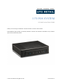
1
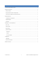
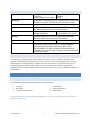
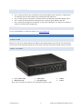
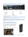
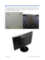
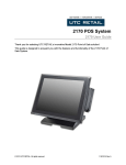
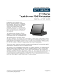
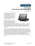
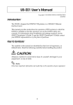
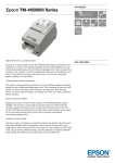
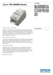
1170 POS SYSTEM 1170 INSTALLATION GUIDE Thank you for selecting UTC RETAIL’s innovative Model 1170 Point of Sale solution! This Installation Guide will help you efficiently install the 1170 POS. The document is intended for use by technical experts who assemble POS systems. © 2015 UTC RETAIL All rights reserved 11933017 Rev A 1170 POS SYSTEM INSTALLATION GUIDE All rights reserved. No part of this document may be reproduced, stored in a retrieval system, or transmitted in any form or by any means, electronic or mechanical, including photocopying, recording, or otherwise, without the prior written permission of UTC RETAIL. This Installation Guide was prepared by UTC RETAIL for use by Qualified Service Personnel only. All attempts have been made to ensure that the information presented in this manual is correct. No liability, expressed or implied, will be assumed by UTC RETAIL, its dealers, or affiliates, for damage resulting from the use of this information. If a unit needs to be shipped to UTC RETAIL for repairs, please return it in the original packaging material and shipping container. If you purchased the 1170 POS System through a dealer, and the dealer is unable to answer your questions, please call UTC RETAIL Technical Support at 1.800.349.0546. This equipment has been tested and found to comply with the limits for a Class “A” digital device, pursuant to Part 15 of the FCC Rules. These limits are designed to provide reasonable protection against harmful interference when the equipment is operated in a commercial environment. This equipment generates, uses, and can radiate radio frequency energy and, if not installed and used in accordance with the instruction manual, may cause harmful interference to radio communications. Operation of this equipment in a residential area is likely to cause harmful interference, in which case the user will be required to correct the interference at his/her own expense. WARNING: CMOS Battery Damage Replace your system’s CMOS RAM battery only with identical CR-2032 3V Lithium-Ion coin cell (or equivalent) battery type to avoid risk of personal injury or physical damage to your equipment. Always dispose of used batteries according to the manufacturer’s instructions, or as required by the local ordinance (where applicable). The damage due to not following this warning will void your motherboard’s manufacture warrantee. All access to internal components is restricted to Authorized Service personnel only. If applicable, the key for this device should be in the possession of Qualified Service Personnel Only and used for access by an Authorized and Qualified Service Person. 11933017 Rev A 2 © 2015 UTC RETAIL All rights reserved CONTENTS 1170 POS System Installation Guide.............................................................................................................................2 Preparing for Installation ...............................................................................................................................................4 Safety Precautions .....................................................................................................................................................4 Site Specifications and Power Requirements ............................................................................................................5 AC Power Line and Data Line Transient Protection .................................................................................................5 Product Information .......................................................................................................................................................5 1170 POS System Components .................................................................................................................................5 Peripheral Support .....................................................................................................................................................6 User Guide .................................................................................................................................................................6 Installing the 1170 POS Workstation ............................................................................................................................6 Power Cord ................................................................................................................................................................6 Front I/O Panel ..........................................................................................................................................................6 Rear I/O Panel ...........................................................................................................................................................7 System Orientation ....................................................................................................................................................7 Horizontal ..............................................................................................................................................................7 Vertical ..................................................................................................................................................................7 LCD VESA Mount ................................................................................................................................................8 Configuration .................................................................................................................................................................9 COM Setup ................................................................................................................................................................9 mini-PCIe Slot Options..............................................................................................................................................9 Hard Drive Removal ......................................................................................................................................................9 11933017 Rev A 3 © 2015 UTC RETAIL All rights reserved PREPARING FOR INSTALLATION SAFETY PRECAUTIONS DANGER: High Voltage This unit contains high voltage. There is a risk of electrical shock if the case is opened. If service is required, contact UTC RETAIL (UTC). WARNING: Access to Internal Components All access to internal components of the POS unit is restricted to Authorized Service Personnel only. Opening the case or service by anyone else will automatically void the warranty on this product. WARNING: CMOS Battery Damage Replace your system’s CMOS RAM battery only with the identical CR-2032 3V Lithium-Ion coin cell (or equivalent) battery type to avoid risk of personal injury or physical damage to your equipment. Always dispose of used batteries according to the manufacturer’s instructions, or as required by the local ordinance (where applicable). The damage due to not following this warning will void the warranty on this product WARNING: Connect AC Power Cable Last To avoid accidental power-up during POS installation, connect the AC Power Cable last. WARNING: Electrical Shock To avoid electric shock, do not connect safety extra low voltage (SELV) circuits to telephone network voltage (TNV) circuits. LAN ports contain SELV circuits, and WAN ports contain TNV circuits. Some LAN and WAN ports use RJ-45 connectors. Use caution when connecting cables. WARNING: Attachment of Peripherals or Accessories Damage to the computer’s motherboard components may occur if AC power is not removed from the unit prior to attaching any peripherals or accessories. Do not hot plug to the serial ports; turn off the POS before connecting serial port cables. CAUTION: If this POS contains a WLAN accessory: This POS complies with FCC radiation exposure limits for an uncontrolled environment. The POS should be installed and operated at a distance greater than 20 centimeters (8 inches) between yourself and any bystander to comply with the Radiation Exposure Requirements. Changes or modifications not expressly approved by UTC RETAIL could void your authority to operate the POS. 11933017 Rev A 4 © 2015 UTC RETAIL All rights reserved SITE SPECIFICATIONS AND POWER REQUIREMENTS Power Requirements Voltage Frequency Current (adapter’s max output) 120 VAC ± 10% 50/60 Hz 3.42A Site Wiring A dedicated, unswitched power line is recommended. The AC outlet should be close to the 1170 POS. Do not use extension cords. Environmental Conditions Temperature Constant operation at or near the temperature limits stated below should be avoided. Do not exceed the limits shown. Operating temperature: Storage temperature: Humidity 0°C to 40°C (32°F to 104°F) -20°C to 60°C (-4°F to 140°F) Constant operation at or near the humidity limits stated below should be avoided. Do not exceed the limits shown. Humidity Airflow Requirements Up to 90% non-condensing The ambient air temperature must not exceed 40°C (104°F). Do not block the air vents on any side of the 1170 POS Workstation. Airflow through these vents is required for system cooling. Do not install the 1170 POS in a location not having sufficient ventilation. Leave several inches of clearance on all sides where the air vents are located. AC POWER LINE AND DATA LINE TRANSIENT PROTECTION The 1170 POS is a modern computer that can interface with a large variety of peripherals. This POS system represents a significant financial investment for your site. As such, it must be protected against energy transients (lightening strikes, switching transients), complete power loss or brownouts as you would protect any piece of computer equipment. UTC RETAIL has a large variety of power and data line conditioner equipment and uninterruptible power supplies (UPS) that can be sized for your system; contact your UTC RETAIL representative for information. PRODUCT INFORMATION 1170 POS SYSTEM COMPONENTS You will find the following components inside the 1170 POS System box: 1170 POS Safety Sheet A/C adapter and power cord Vertical Stand VESA mount bracket Hardware bag Note: Options that were purchased from UTC RETAIL such as a keyboard, customer display and printer may be shipped in separate boxes. 11933017 Rev A 5 © 2015 UTC RETAIL All rights reserved PERIPHERAL SUPPORT The 1170 POS System accepts a standard PC keyboard and standard mouse with a PS/2 or USB interface. UTC RETAIL P/N 10718020 contains both a USB keyboard and USB mouse. The 1170 POS System was designed to coordinate with the UTC RETAIL PD1200 Pole Display option. The 1170 POS System supports many different printers, such as the Epson H6000 or TM-T88. The 1170 POS System supports UTC RETAIL 15” flat panel LCD displays. The displays are available in touch screen and non-touch configurations. USER GUIDE To view or download the 1170 POS User Guide, go to www.utcretail.com INSTALLING THE 1170 POS WORKSTATION POWER CORD Plug the AC cord into AC adapter and mate the adapter’s barrel plug with the power jack in the rear of the chassis. Lay the system on the countertop and route the power cables so they does not interfere with the system’s operation. FRONT I/O PANEL 1. 2. Power switch & LED HDD activity LED 3. 4. Audio Output Microphone Input 5. 6. USB 2.0 USB 3.0 Review the 1170 POS User Guide for more information on these I/O ports. 11933017 Rev A 6 © 2015 UTC RETAIL All rights reserved REAR I/O PANEL 1. Kensington Lock 7. HDMI 2. AC Adapter 8. COM1 3. PS/2 mouse 9. COM2 4. PS/2 keyboard 10. LAN 1 5. Parallel 11. USB 2.0 6. DVI 12. USB 2.0 Review the 1170 POS User Guide for more information on these I/O ports. 13. 14. 15. 16. LAN 0 USB 2.0 USB 2.0 WLAN dipole SYSTEM ORIENTATION The 1170 POS versatility can be seen in the various available mounting orientations. HORIZONTAL This orientation is seen in the image on the manual’s cover page. Place the 1170 POS flat on the table or counter top. Connect power and system cables and turn on the 1170. VERTICAL Remove the vertical stand bracket from the system box. Align the tabs on the bracket with the slots in the 1170 POS chassis right side. Slide the stand forward until you feel the stand lock into place. Stand the 1170 POS on the countertop. Connect power and system cables and turn on the 1170. To remove the stand, gently and slightly push in the release tab and slide the stand rearward. 11933017 Rev A 7 © 2015 UTC RETAIL All rights reserved LCD VESA MOUNT Remove the VESA bracket and hardware bag from the system box. Install the 4 studs onto the bottom side of the 1170. Install the VESA bracket onto the rear of your LCD using the 4 screws and observing the “UP” arrow. Align the 4 studs with the 4 keyhole slots and hang the 1170 on the bracket in any of 4 rotation orientations. Connect power and system cables and turn on the 1170. 11933017 Rev A 8 © 2015 UTC RETAIL All rights reserved CONFIGURATION COM SETUP The configuration of the I/O lines of COM2 may be modified from standard RS232. Use the 1170 User Manual to review motherboard terminal block settings. MINI-PCIE SLOT OPTIONS The mini-PCIe slot can hold an optional WLAN card. Use the 1170 User Manual to find details. HARD DRIVE REMOVAL Use the 1170 User Manual for details on accessing the HDD. Please call UTC RETAIL’s Technical Support at 800.349.0546 if you have any problems not addressed in the Troubleshooting Procedures or has questions about other sections of this documentation. 11933017 Rev A 9 © 2015 UTC RETAIL All rights reserved