1
3170 Series
Touch Screen POS Workstation
USER GUIDE
Congratulations on your purchase of UTC
RETAIL’s innovative 3170 Series Touch
Screen POS Workstation. The 3170
Series was designed to conserve counter
space and it comes standard with a rich
set of features. This guide will acquaint
you with the 3170 Series Workstation’s
features and functionality.
This document provides instruction and
information for product users, and may
not be used for any purpose other than its
intended use. This document must be
downloaded in its entirety; it may not be reproduced, stored or transmitted in part without the
prior written permission of UTC RETAIL. All attempts have been made to ensure that the
information presented in this document is correct. No liability expressed or implied, will be
assumed by UTC RETAIL, its dealers, or affiliates, for damage resulting from the use of this
information.
The 3170 Series Touch Screen POS Workstation complies with UL60950 requirements. This
equipment has been tested and found to comply with the limits for a Class “A” digital device,
pursuant to Part 15 of the FCC Rules. These limits are designed to provide reasonable protection
against harmful interference when the equipment is operated in a commercial environment. This
equipment generates, uses, and can radiate radio frequency energy and, if not installed and used
in accordance with the instruction manual, may cause harmful interference to radio
communications. Operation of this equipment in a residential area is likely to cause harmful
interference, in which case the user will be required to correct the interference at his/her own
expense.
3170 Series™ is a registered trademark of UTC RETAIL
2009 UTC RETAIL. All rights reserved.
11827027 Rev A
Contents
PRODUCT INFORMATION ........................................................................................................................................... 3
Product Components ....................................................................................................................................... 3
Product Safety ................................................................................................................................................. 3
Technical Specifications .................................................................................................................................. 4
Operating System and Drivers ..................................................................................................................................4
Installing Customer-Specific Applications ...............................................................................................................4
Care and Cleaning .....................................................................................................................................................4
DIAGNOSTICS AND TROUBLESHOOTING ................................................................................................................. 4
System Boot .................................................................................................................................................... 4
SERVICE AND TECHNICAL SUPPORT ....................................................................................................................... 5
TECHNICAL INFORMATION ......................................................................................................................................... 5
UTC RETAIL 3170 Series Motherboard Jumpers ............................................................................................ 5
Motherboard Jumpers and Connectors............................................................................................................ 6
Serial Port Power Selection ............................................................................................................................. 6
Cash Drawer Port Power Selection.................................................................................................................. 9
Audio Line-out Jack ......................................................................................................................................... 9
+24VDC Power Jack........................................................................................................................................ 9
APPENDIX A................................................................................................................................................................ 10
Programming Guide: 3170 Rear Customer Display ....................................................................................... 10
Display Control Features and Commands .............................................................................................................. 10
Serial Operating Parameters Selection .................................................................................................................... 14
Appendix B Programming Guide: 3170 Cash Drawer Driver ......................................................................... 16
11823027 Rev A
-2-
© 2012 UTC RETAIL
Product Information
The 3170 Series Touch Screen POS Workstation is designed for use in restaurants, convenience stores, cafeterias
and other specialty retail establishments. It is highly configurable, has easy access to connectors, and a large
selection of interface ports for connectivity to printers, cash drawers, scanners, keyboards, and other peripherals.
Product Components
The 3170 Series product includes:
• 3170 Series main unit
• AC Line Cord
Depending on the configuration you have purchased, the following optional components may also be provided:
• Magnetic Strip Reader (MSR) unit and Installation Guide
• Rear Customer Display (RCD) unit and Installation Guide
• WLAN Kit (802.11 b/g/n)
Product Safety
DANGER: High Voltage
This unit contains high voltage. There is a risk of electrical shock if the case is opened. If service is required, contact an
authorized service agent or UTC RETAIL.
WARNING: CMOS Battery Damage
Replace your system's battery only with CR-2032 (or equivalent) 3V Lithium-Ion coin cell battery to avoid risk of
personal injury or physical damage to your equipment. Always dispose of used batteries according to local ordinance,
where applicable. Any damage due to not following this warning will void your warranty
WARNING: Access to Internal Components
All access to internal components of the 3170 Series unit is restricted to Authorized Service Personnel only. Opening
the case or service by anyone else will automatically void the warranty on this product.
WARNING: Laser Radiation (CD or DVD Drive)
Invisible or visible laser radiation may be present when Optical Devices are present. When open, do not stare into the
beam or view directly with optical instruments.
WARNING: Electrical Shock
Use caution when connecting cables. To avoid electric shock, do not connect safety extra-low voltage (SELV) circuits
to telephone-network voltage (TNV) circuits. Local Area Network (LAN) ports contain SELV circuits, and telephone
ports contain TNV circuits. Some LAN ports and some telephone ports use RJ-45 connectors.
CAUTION:
If your 3170 contains the WLAN accessory: This 3170 complies with FCC radiation exposure limits for an uncontrolled
environment. The 3170 should be installed and operated at a distance greater than 20 centimeters (8 inches) between
yourself and any bystander to comply with the Radiation Exposure Requirements. Changes or modifications not
expressly approved by UTC RETAIL could void your authority to operate the 3170.
CAUTION:
Damage to the logic module components may occur if AC power is not removed from the product prior to attaching any
accessories.
CAUTION:
Do not hot plug to the rear panel serial ports. Turn off the 3170 Series Unit before connecting serial port cables.
CAUTION:
Do not use the Magnetic Stripe Reader (MSR) unit as a handle when moving or carrying the 3170 Series.
© 2012 UTC RETAIL
-3-
11823027 Rev A
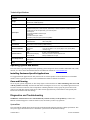
Technical Specifications
3170 Series Touch Screen POS Workstation
Processor
Intel Pentium G850 Dual Core
Storage
Hard disk drive (HDD), 320GB
Second HDD, 320GB (Optional)
Memory
Up to 16 GB DDR3 DRAM (2 DIMM slots)
Input/Output
(1) Cash drawer ports, +12VDC or +24VDC, default setup for +24VDC cash drawer
(4) RS232 serial ports on rear I/O panel, default setup is COM1 unpowered, COM2-4 powered
(5) USB ports on rear I/O panel and (1) on front I/O panel
(1) SVGA port
(1) 10/100/1000 Base-T Ethernet port
(1) PS/2 port
(1) Audio Line-out jack, 3.5mm
(1) 24VDC power jack (Epson printer compatible)
Display
Size/type:
Pixels/resolution:
Touch Screen
Touch screen: 5-wire resistive (COM5 interface)
Mechanical Features
Safety:
Dimensions:
Weight:
UL60950 Listed
15 in. (38 cm) wide x 17 in. (43 cm) high x 15 in. (38 cm) deep
~17 lbs(7.7 kg)
Optional Features
MSR:
Rear Customer Display:
Internal WLAN:
ID Tech, 3-track (USB interface)
2x20 VFD, 10.5mm x 5.5mm character size
Factory installed, 802.11 b/g/n
Power Requirements
110 VAC, 60 Hz
0.5A (typical)
RoHS
Compliant
15 in. (38 cm) TFT LCD flat panel
1024 x 768 pixels
Operating System and Drivers
The 3170 Series is typically shipped with an operating system and specific drivers installed. Individual video, audio,
network, etc. drivers can be downloaded from the UTC RETAIL website at: www.utcretail.com.
Installing Customer-Specific Applications
It is suggested that all applications be fully tested on the 3170 Series product to ensure that there are no hardware
conflicts. This is typically done prior to store installation and within a technical environment.
Care and Cleaning
Never use pens, pencils, fingernails, or other sharp objects on the Touch Screen. These will damage the screen and
void the product’s warranty. Turn the unit OFF before cleaning the screen or case. Any standard glass cleaner can
be used to clean the touchscreen, but avoid products containing ammonia. Always spray the glass cleaner on the
cloth or towel and then clean the touch screen. Glass cleaner sprayed directly on the monitor could possibly leak
inside a non-sealed unit and cause damage.
Diagnostics and Troubleshooting
WARNING: Unauthorized service will automatically void the warranty on the product(s). Contact UTC
RETAIL Technical Support at 1.800.349.0546 or (585) 924.9500 if you have any questions.
System Boot
The 3170 POS has a BIOS that is based upon the Unified Extensible Firmware Interface (UEFI) specification. This
new power-up specification allows for a much faster system boot to the Windows® Desktop.
11823027 Rev A
-4-
© 2012 UTC RETAIL
To perform a one-time modified boot order, keep pressing F7 during the boot process until the Boot Order menu
appears.
To access the BIOS during the system boot, keep pressing Delete during the boot process unit until the BIOS Main
screen appears.
Service and Technical Support
Assistance and customer service are available from your dealer or authorized service provider. If your dealer or
service provider cannot answer your questions or provide satisfactory service, call UTC RETAIL Technical Support.
When calling for assistance or service information, please be ready to provide the serial number, which can be found
on a label on the bottom of the 3170 Series. If the product needs to be returned to our repair facility, please use the
original packing material and shipping carton.
For assistance, service and product information, contact:
UTC RETAIL
100 Rawson Road
Victor, NY 14564
Phone: 1.800.349.0546 or (585) 924.9500
Fax: (585) 924.1434
www.utcretail.com
Intel and Pentium are registered trademarks of Intel Corporation. Windows is a registered trademark of Microsoft Corporation.
Technical Information
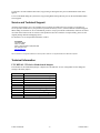
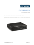
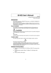
UTC RETAIL 3170 Series Motherboard Jumpers
Listed below are the motherboard jumpers. Only the JP3, JP4 and JP11 are user configurable. Do not change the
settings of the other jumpers.
Terminal Block
JP3
JP4
JP5
JP6
JP7
JP8
JP9
JP10
JP11
JP13
JP14
© 2012 UTC RETAIL
Function
COM1 & COM2 Power Setting
COM3 & COM4 Power Setting
CMOS Reset
System Indicator (factory use)
LCD backlight setting
LCD ID Setting
Cash Drawer Power Setting
System Reset
ME update
-5-
11823027 Rev A
Motherboard Jumpers and Connectors
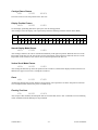
Serial Port Power Selection
The 3170 Series COM1 serial port is shipped factory set for modem operation. Pin 1 is for DCD (Data Carrier
Detect), pin 9 for RI (Ring Indicator). Therefore, JP3 (COM1) has pins 1 and 2 jumpered.
COM2, COM3 and COM4 are shipped factory set to provide +5VDC on Pin 9. Therefore, JP3 has pins 9 and 10
jumpered, JP7 and JP6 have pins 1 and 2 jumpered, and pins 9 and 10 jumpered.
11823027 Rev A
-6-
© 2012 UTC RETAIL
Each of these ports may be configured to provide +5V or +12V output to Pin 1 or Pin 9 to power your serial port
peripherals. They must not be setup to provide power to Pin 1 and Pin 9 simultaneously. Do not hot plug onto
a COM port configured to provide power to pin 1 or pin 9. You run a risk of shorting the powered pin to the
port’s shield while hot plugging. By default, COM2, COM3 and COM4 have +5VDC on pin 9.
▲ = factory default setting
COM1 and COM2 Power Settings
JP3
Function
(1 – 2) (3 – 4) (5 – 6) (7 – 8) (9 – 10) (11 – 12)
▲RI
COM1 Pin 9
+5V
+12V
RI
COM2 Pin 9
▲+5V
+12V
© 2012 UTC RETAIL
1
2
1
2
1
2
1
2
1
2
1
2
-7-
3
4
3
4
3
4
3
4
3
4
3
4
5
6
5
6
5
6
5
6
5
6
5
6
7
8
7
8
7
8
7
8
7
8
7
8
9
10
9
10
9
10
9
10
9
10
9
10
11
12
11
12
11
12
11
12
11
12
11
12
11823027 Rev A
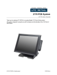
COM3 and COM4 Power Settings
COM3 and COM4 can be set to provide power to your serial device. The voltage can be set to +5V or +12V by
setting jumper JP4 on the motherboard. When enabled, the power is available on pin 9 of the DB9 connector. By
default, this power option is enabled in the BIOS.
Enable COM3/COM4 power in BIOS
1.
Power on the system, and press the
<DEL> key when the system is booting up
to enter the BIOS Setup utility.
2.
Select the Advanced tab
3.
Select Power Configuration
COM/VGA/CD Ports and press <Enter> to
go to display the available options.
4.
To enable the power, select COM3
Power Setting or COM4 Power setting and
press <Enter>. Select Power and press
<Enter>.
5.
Save the change by pressing F10.
JP4
Function
(1 – 2) (3 – 4) (5 – 6) (7 – 8)
▲+5V
COM3 Pin 9
+12V
▲+5V
COM4 Pin 9
+12V
11823027 Rev A
1
2
1
2
1
2
1
2
3
4
3
4
3
4
3
4
5
6
5
6
5
6
5
6
7
8
7
8
7
8
7
8
-8-
© 2012 UTC RETAIL
Cash Drawer Port Power Selection
The 3170 Series Cash Drawer port is shipped factory set to drive a +24VDC cash drawer circuit. Therefore, JP11
has pins 1 and 2 jumpered.
Cash Drawer Port Power Settings
Function
JP3 (1 – 2) (3 – 4)
Cash Drawer +12VDC
1 3
2 4
▲Cash Drawer +24VDC
1 3
2 4
Audio Line-out Jack
The 3170 Series 3.5mm line-out jack will provide an audio output signal to an external pair of computer speakers.
These speakers must be powered by a user supplied external power source.
+24VDC Power Jack
The 3170 Series +24VDC power jack will provide power to operate Epson POS printers. Contact UTC RETAIL for
custom cable part number 11029567.
© 2012 UTC RETAIL
-9-
11823027 Rev A
Appendix A
Programming Guide: 3170 Rear Customer Display
Note: If you are using the customer display with an OPOS, JavaPOS, or POS for .Net application, this document
does not apply to you. You will need to use the correct driver available on the UTC RETAIL web site at
www.utcretail.com.
The 3170 Rear Customer Display (RCD) operates by converting recognized data, supplied by serial communication,
into a display message. The supplied data may also contain commands that control the display.
The 3170 RCD uses a limited command structure for display control, requiring minimal programming effort. The
table below lists the display control features of the 3170 RCD and control codes (in ASCII, DEC, and HEX
expression). The display control command structure, with examples, is described in this section.
Display Control Features and Commands
The following table outlines the 3170 RCD control features and commands:
Feature
ASCII
DEC
HEX
Dimming
<EOT>x
04, x
04, x
Back Space
<BS>
08
08
Horizontal Tab
<HT>
09
09
Line Feed
<LF>
10
0A
Carriage Return
<CR>
13
0D
Display Position
<DLE>p
16, p
10, p
Normal Display
<DC1>
17
11
Vertical Scrolling
<DC2>
18
12
Reset
<US>
31
1F
Flashing Text Start
<FS>
28
1C
Flashing Text Stop
<GS>
29
1D
Clear to End of Line
<CAN>
24
18
Clear to End of Display
<EM>
25
19
Home and Clear Display
<RS>
30
1E
11823027 Rev A
- 10 -
© 2012 UTC RETAIL
Dimming Feature
<EOT>x
04 DEC
04 HEX
Brightness can be controlled to four levels by using this function. After writing 04h to the display, the next byte sent
will set the brightness. The table below lists the display dimming commands in ASCII, DEC and HEX expression.
Dimming Level
ASCII
DEC
HEX
100 %
-
255
FF
60 %
‘
96
60
40 %
@
64
40
20 %
Space
32
20
Back Spacing Feature
<BS>
08 DEC
08 HEX
When the backspace command is executed, the write-in position is shifted to the left one position, erasing the
character, if any, in that position. When the write-in position is in the first (read from left to right) position of the
first row, the write-in moves to the last position of the second row. When the write-in is in the first position of the
second row, the write-in moves to the last position of the first row.
Horizontal Tab Feature
<HT>
09 DEC
09 HEX
DC1 Mode (Normal Display Mode)
The write-in position is shifted to the right one position. When the write-in is in the last position of the first row, the
write-in moves to the first position of the second row. When the write-in is in the last position of the second row, the
write-in moves to the first position of the first row.
DC2 Mode (Vertical Scroll Mode)
When the write-in is in the last position of the second row, the characters displayed in the second row are shifted up
to the first row and the write-in moves to the first position of the second row. This action clears the second row.
Line Feeding Feature
<LF>
10 DEC
0A HEX
DC1 Mode (Normal Display Mode)
The write-in moves up or down to another row, staying in the same horizontal position.
DC2 Mode (Vertical Scroll Mode)
When the write-in is in the second row, the characters displayed there are shifted up to the first row, leaving the
write-in at its present position. This action clears the second row. When the write-in is in the first row, the write-in
moves down to the second row.
© 2012 UTC RETAIL
- 11 -
11823027 Rev A
Carriage Return Feature
<CR>
13 DEC
0D HEX
The write-in moves to the first position of the same row.
Display Position Feature
<DLE>
16 DEC
10 HEX
Use the display positioning function to specify the write-in starting position.
After writing a 10h to the display, enter a position byte from the following Character Position Chart (HEX):
Row
Position Bytes
1
00
01
02
03
04
05
06
07
08
09
0A
0B
0C
0D
0E
0F
10
11
12
13
2
14
15
16
17
18
19
1A
1B
1C
1D
1E
1F
20
21
22
23
24
25
26
27
Normal Display Mode Feature
<DC1>
17 DEC
11 HEX
After writing a character, the write-in is shifted automatically to the right one position. When the write-in is in the
last position of the first row, the write-in moves to the first position of the second row. When the write-in is in the
last position of the second row, the write-in moves to the first position of the first row.
Vertical Scroll Mode Feature
<DC2>
18 DEC
12 HEX
After writing the characters up to the last position of the second row, all characters displayed in the second row are
shifted to the upper row (first row), clearing the second row.
Reset
<US>
31 DEC
1F HEX
All characters displayed are erased, and the write-in position (cursor position) is set in the first position of the first
row. The display mode returns to the power-on default set-up.
Flashing Text Start
<FS>
28 DEC
1C HEX
After receipt of this command, all subsequent data received will flash, until a <GS> command is received. Flashing
will be terminated with the flashing text stop command.
11823027 Rev A
- 12 -
© 2012 UTC RETAIL
Flashing Text Stop
<GS>
29 DEC
1D HEX
After receipt of this command, the characters following will not flash.
Clear to End of Line Feature
<CAN>
24 DEC
18 HEX
This command will clear out the display from the current write-in position to the end of the current line. The current
write-in position will not change.
Clear to End of Display Feature
<EM>
25 DEC
19 HEX
This command will clear out the display from the current write-in position to the end of the second line. The current
write-in position will not change.
Home and Clear Display Feature
<RS>
30 DEC
1E HEX
This command will clear the display and move the write-in position to the first position of the first row.
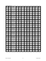
Display Character Codes
For a full listing of the display character codes used by the 3170 RCD, refer to the ASCII Character Set in the table
on the following pages.
© 2012 UTC RETAIL
- 13 -
11823027 Rev A
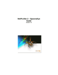
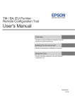
Serial Operating Parameters Selection
The 3170 RCD ships factory set for 9600 baud, 8 data bits, and no parity. If desired, the baud and parity can be
changed with a few simple steps.
Remove the lens cover by depressing the 2 tabs on the bottom of the display. While the tabs are depressed, carefully
rotate the lens cover off of the display, starting at the bottom of the display. Once the lens is removed, the headers
used to select the baud rate and parity will be visible. They are located on the printed circuit board to the right of the
vacuum fluorescent display. The shorting jumpers (supplied with unit) can be added to change both the baud rate
and/or parity.
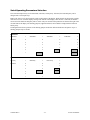
The diagram below shows positions of the shorting jumpers needed for different baud rates and parities. Up to 4
shorting jumpers may be needed.
BAUD RATE
9600 Baud
.
.
7
DEFAULT
.
.
.
2400 Baud
.
.
7
6
.
.
.
5
.
.
.
4
.
.
.
4800 Baud
.
.
7
6
.
.
.
5
.
.
.
4
3
.
.
.
2
.
.
.
1
No Parity
.
.
7
DEFAULT
.
.
.
19.2K Baud
.
.
7
6
.
.
6
.
5
.
.
5
.
.
4
.
.
4
3
.
.
3
.
.
3
.
2
.
.
2
.
.
2
.
.
1
.
.
1
.
.
1
.
.
7
Even Parity .
.
7
6
.
.
6
.
.
6
.
5
.
.
5
.
.
5
.
.
4
.
.
4
.
.
4
.
.
3
.
.
3
.
.
3
.
.
2
.
.
2
.
.
2
.
.
1
.
.
1
.
.
1
PARITY
11823027 Rev A
Odd Parity
- 14 -
© 2012 UTC RETAIL
ASCII Character Set
DEC
HEX
ASCII
DEC
HEX
ASCII
DEC
HEX
ASCII
DEC
HEX
ASCII
0
00
Ctrl-@ (NUL)
32
20
Space
64
40
@
96
60
`
1
01
Ctrl-A (SOH)
33
21
!
65
41
A
97
61
a
2
02
Ctrl-B (STX)
34
22
“
66
42
B
98
62
b
3
03
Ctrl-C (ETX)
35
23
#
67
43
C
99
63
c
4
04
Ctrl-D (EOT)
36
24
$
68
44
D
100
64
d
5
05
Ctrl-E (ENQ)
37
25
%
69
45
E
101
65
e
6
06
Ctrl-F (ACK)
38
26
&
70
46
F
102
66
f
7
07
Ctrl-G (BEL)
39
27
‘
71
47
G
103
67
g
8
08
Ctrl-H (BS)
40
28
(
72
48
H
104
68
h
9
09
Ctrl-I (HT)
41
29
)
73
49
I
105
69
i
10
0A
Ctrl-J (LF)
42
2A
*
74
4A
J
106
6A
j
11
0B
Ctrl-K (VT)
43
2B
+
75
4B
K
107
6B
k
12
0C
Ctrl-L (FF)
44
2C
,
76
4C
L
108
6C
l
13
0D
Ctrl-M (CR)
45
2D
-
77
4D
M
109
6D
m
14
0E
Ctrl-N (SO)
46
2E
.
78
4E
N
110
6E
n
15
0F
Ctrl-O (SI)
47
2F
/
79
4F
O
111
6F
o
16
10
Ctrl-P (DLE)
48
30
0
80
50
P
112
70
p
17
11
Ctrl-Q (DC1)
49
31
1
81
51
Q
113
71
q
18
12
Ctrl-R (DC2)
50
32
2
82
52
R
114
72
r
19
13
Ctrl-S (DC3)
51
33
3
83
53
S
115
73
s
20
14
Ctrl-T (DC4)
52
34
4
84
54
T
116
74
t
21
15
Ctrl-U (NAK)
53
35
5
85
55
U
117
75
u
22
16
Ctrl-V (SYN)
54
36
6
86
56
V
118
76
v
23
17
Ctrl-W (ETB)
55
37
7
87
57
W
119
77
w
24
18
Ctrl-X (CAN)
56
38
8
88
58
X
120
78
x
25
19
Ctrl-Y (EM)
57
39
9
89
59
Y
121
79
y
26
1A
Ctrl-Z (SUB)
58
3A
:
90
5A
Z
122
7A
z
27
1B
Ctrl-[ (ESC)
59
3B
;
91
5B
[
123
7B
{
28
1C
Ctrl-\ (FS)
60
3C
<
92
5C
\
124
7C
|
29
1D
Ctrl-] (GS)
61
3D
=
93
5D
]
125
7D
}
30
1E
Ctrl-^ (RS)
62
3E
>
94
5E
^
126
7E
~
31
1F
Ctrl-_ (US)
63
3F
?
95
5F
_
127
7F
DEL
© 2012 UTC RETAIL
- 15 -
11823027 Rev A
Appendix B
Programming Guide: 3170 Cash Drawer Driver
Note: If you are using the cash drawer with an OPOS, JavaPOS, or POS for .Net application, this document does
not apply to you. You will need to use the correct driver available on the UTC RETAIL web site at
www.utcretail.com.
Microsoft® Windows® Softwarei
If you purchased your 3170 POS with a Windows® operating system pre-installed on it, you will find a Cash Drawer
Utility folder within the Drivers folder on the hard drive. In the Cash Drawer Utility folder there are two additional
folders. In cdbox48C there exists both source code and executables for DOS and Windows environments. In the
3170 Cash Drawer folder, there is Visual Studio source code and an executable.
11823027 Rev A
- 16 -
© 2012 UTC RETAIL