1
OSCAT
Network
Network:LIBRARY
:LIBRARY
Documentation In English
Version 1.21
Chapter
Table of Contents
1. Legal...................................................................................... 7
1.1.
1.2.
1.3.
1.4.
1.5.
Disclaimer................................................................................................................... 7
License Terms............................................................................................................. 7
Intended Use............................................................................................................... 8
Registered trademarks................................................................................................ 8
Other.......................................................................................................................... 8
2. Introduction............................................................................ 9
2.1.
2.2.
2.3.
2.4.
2.5.
Objectives................................................................................................................... 9
Conventions.............................................................................................................. 10
Test environment and conditions.............................................................................. 11
Releases................................................................................................................... 12
Support..................................................................................................................... 13
3. Demo-Programs....................................................................14
3.1. Demo programs........................................................................................................ 14
4. Data Types of the NETWORK-Library.......................................16
4.1. DLOG_DATA............................................................................................................... 16
4.2. us_LOG_VIEWPORT.................................................................................................... 16
4.3. URL........................................................................................................................... 17
4.4. us_TN_INPUT_CONTROL............................................................................................ 17
4.5. us_TN_INPUT_CONTROL_DATA................................................................................... 18
4.6. us_TN_MENU............................................................................................................. 19
4.7. us_TN_MENU_POPUP................................................................................................. 20
4.8. us_TN_SCREEN.......................................................................................................... 21
4.9. FILE_PATH_DATA........................................................................................................ 22
4.10. FILE_SERVER_DATA................................................................................................. 22
4.11. IP2GEO.................................................................................................................... 22
4.12. IP_C......................................................................................................................... 23
4.13. IP_FIFO_DATA.......................................................................................................... 24
4.14. LOG_CONTROL........................................................................................................ 24
4.15. NET_VAR_DATA........................................................................................................ 25
4.16. PRINTF_DATA........................................................................................................... 25
4.17. UNI_CIRCULAR_BUFFER_DATA................................................................................. 26
4.18. VMAP_DATA............................................................................................................. 26
4.19. XML_CONTROL........................................................................................................ 27
4.20. WORLD_WEATHER_DATA......................................................................................... 28
2
Version 1.21
Chapter
4.21. YAHOO_WEATHER_DATA.......................................................................................... 29
5. Other Functions....................................................................34
5.1. ELEMENT_COUNT...................................................................................................... 34
5.2. ELEMENT_GET........................................................................................................... 34
5.3. NETWORK_VERSION.................................................................................................. 35
6. Device Driver........................................................................ 36
6.1.
6.2.
6.3.
6.4.
6.5.
6.6.
6.7.
6.8.
6.9.
IRTRANS.................................................................................................................... 36
IRTRANS_DECODE..................................................................................................... 36
IRTRANS_RCV_1......................................................................................................... 37
IRTRANS_RCV_4......................................................................................................... 39
IRTRANS_RCV_8......................................................................................................... 39
IRTRANS_SERVER...................................................................................................... 40
IRTRANS_SND_1........................................................................................................ 42
IRTRANS_SND_4........................................................................................................ 43
IRTRANS_SND_8........................................................................................................ 44
7. Data Logger.......................................................................... 46
7.1. DATA-LOGGER........................................................................................................... 46
7.2. DLOG_BOOL.............................................................................................................. 48
7.3. DLOG_DINT............................................................................................................... 49
7.4. DLOG_DT................................................................................................................... 50
7.5. DLOG_REAL............................................................................................................... 51
7.6. DLOG_STRING........................................................................................................... 52
7.7. DLOG_STORE_FILE_CSV............................................................................................ 52
7.8. DLOG_STORE_RRD.................................................................................................... 54
7.9. DLOG_FILE_TO_FTP................................................................................................... 63
7.10. DLOG_FILE_TO_SMTP.............................................................................................. 66
7.11. UNI_CIRCULAR_BUFFER........................................................................................... 69
8. Converter.............................................................................72
8.1.
8.2.
8.3.
8.4.
8.5.
8.6.
8.7.
8.8.
8.9.
3
BASE64..................................................................................................................... 72
BASE64_DECODE_STR............................................................................................... 72
BASE64_DECODE_STREAM........................................................................................ 73
BASE64_ENCODE_STR............................................................................................... 74
BASE64_ENCODE_STREAM........................................................................................ 74
HTML_DECODE.......................................................................................................... 75
HTML_ENCODE.......................................................................................................... 76
IP4_CHECK................................................................................................................ 77
IP4_DECODE.............................................................................................................. 77
Version 1.21
Chapter
8.10.
8.11.
8.12.
8.13.
8.14.
8.15.
8.16.
8.17.
8.18.
8.19.
8.20.
8.21.
8.22.
8.23.
8.24.
IP4_TO_STRING....................................................................................................... 78
IS_IP4...................................................................................................................... 78
IS_URLCHR.............................................................................................................. 79
MD5_AUX................................................................................................................ 79
MD5_STR................................................................................................................. 80
MD5_STREAM.......................................................................................................... 80
MD5_TO_STRH........................................................................................................ 82
RC4_CRYPT_STREAM............................................................................................... 82
SHA1_STR............................................................................................................... 83
SHA1_STREAM........................................................................................................ 84
SHA1_TO_STRH....................................................................................................... 85
STRING_TO_URL...................................................................................................... 86
URL_DECODE.......................................................................................................... 87
URL_ENCODE.......................................................................................................... 87
URL_TO_STRING...................................................................................................... 87
9. Network and Communication.................................................89
9.1. DNS_CLIENT.............................................................................................................. 89
9.2. DNS_REV_CLIENT...................................................................................................... 90
9.3. DNS_DYN................................................................................................................... 92
9.4. FTP_CLIENT............................................................................................................... 94
9.5. GET_WAN_IP.............................................................................................................. 96
9.6. HTTP_GET................................................................................................................. 98
9.7. IP2GEO...................................................................................................................... 99
9.8. IP_CONTROL............................................................................................................ 101
9.9. IP_CONTROL2.......................................................................................................... 107
9.10. IP_FIFO.................................................................................................................. 108
9.11. LOG_MSG.............................................................................................................. 111
9.12. LOG_VIEWPORT..................................................................................................... 111
9.13. MB_CLIENT (OPEN MODBUS)................................................................................. 112
9.14. MB_SERVER (OPEN-MODBUS)................................................................................116
9.15. MB_VMAP.............................................................................................................. 118
9.16. PRINT_SF............................................................................................................... 121
9.17. READ_HTTP........................................................................................................... 122
9.18. SMTP_CLIENT........................................................................................................ 123
9.19. SNTP_CLIENT......................................................................................................... 127
9.20. SNTP_SERVER....................................................................................................... 128
9.21. SPIDER_ACCESS.................................................................................................... 129
9.22. SYS_LOG............................................................................................................... 131
9.23. TELNET_LOG......................................................................................................... 135
9.24. TELNET_PRINT....................................................................................................... 137
9.25. XML_READER........................................................................................................ 140
4
Version 1.21
Chapter
10. File-System....................................................................... 147
10.1.
10.2.
10.3.
10.4.
10.5.
10.6.
10.7.
10.8.
CSV_PARSER_BUF.................................................................................................. 147
CSV_PARSER_FILE................................................................................................. 149
FILE_BLOCK........................................................................................................... 152
FILE_PATH_SPLIT.................................................................................................... 153
FILE_SERVER......................................................................................................... 154
INI-DATEIEN........................................................................................................... 159
INI_PARSER_BUF.................................................................................................... 161
INI_PARSER_FILE................................................................................................... 164
11. Telnet-Vision...................................................................... 167
11.1. TELNET_VISION..................................................................................................... 167
11.2. TN_FRAMEWORK................................................................................................... 173
11.3. TN_INPUT_CONTROL............................................................................................. 174
11.4. TN_INPUT_EDIT_LINE............................................................................................. 174
11.5. TN_INPUT_MENU_BAR........................................................................................... 176
11.6. TN_INPUT_MENU_POPUP....................................................................................... 178
11.7. TN_INPUT_SELECT_POPUP..................................................................................... 178
11.8. TN_INPUT_SELECT_TEXT....................................................................................... 180
11.9. TN_RECEIVE.......................................................................................................... 182
11.10. TN_SEND_ROWS.................................................................................................. 183
11.11. TN_SC_ADD_SHADOW......................................................................................... 184
11.12. TN_SC_AREA_RESTORE....................................................................................... 184
11.13. TN_SC_AREA_SAVE.............................................................................................. 185
11.14. TN_SC_BOX......................................................................................................... 186
11.15. TN_SC_FILL.......................................................................................................... 187
11.16. TN_SC_LINE......................................................................................................... 188
11.17. TN_SC_READ_ATTR.............................................................................................. 190
11.18. TN_SC_READ_CHAR............................................................................................. 190
11.19. TN_SC_SHADOW_ATTR........................................................................................ 191
11.20. TN_SC_VIEWPORT............................................................................................... 191
11.21. TN_SC_WRITE...................................................................................................... 192
11.22. TN_SC_WRITE_ATTR............................................................................................ 193
11.23. TN_SC_WRITE_C.................................................................................................. 193
11.24. TN_SC_WRITE_CHAR........................................................................................... 194
11.25. TN_SC_WRITE_EOS.............................................................................................. 195
11.26. TN_SC_XY_ERROR............................................................................................... 195
11.27. TN_SC_XY2_ERROR............................................................................................. 196
12. Network Variables.............................................................197
12.1. NET_VAR............................................................................................................... 197
12.2. NET_VAR_CONTROL.............................................................................................. 199
12.3. NET_VAR_BOOL8................................................................................................... 200
5
Version 1.21
Chapter
12.4.
12.5.
12.6.
12.7.
12.8.
NET_VAR_BUFFER.................................................................................................. 201
NET_VAR_DWORD8............................................................................................... 202
NET_VAR_REAL8.................................................................................................... 202
NET_VAR_STRING.................................................................................................. 203
NET_VAR_X8.......................................................................................................... 204
13. Weather Data.................................................................... 206
13.1.
13.2.
13.3.
13.4.
13.5.
13.6.
13.7.
MOON_PHASE....................................................................................................... 206
YAHOO_WEATHER................................................................................................. 207
YAHOO_WEATHER_DESC_DE................................................................................. 210
YAHOO_WEATHER_ICON_OSCAT............................................................................ 211
WORLD_WEATHER................................................................................................. 211
WORLD_WEATHER_DESC_DE................................................................................ 214
WORLD_WEATHER_ICON_OSCAT........................................................................... 215
14. Visualization...................................................................... 216
14.1. VISU-WEATHER...................................................................................................... 216
14.2. Moon Graphics...................................................................................................... 219
14.3. Wind charts........................................................................................................... 220
6
Version 1.21
Chapter 1.
Legal
1. Legal
Die OSCAT Network Bibliothek defniert neben den Standard Datentypen
weitere Datentypen. Diese werden innerhalb der Bibliothek verwendet,
können aber jederzeit von Anwender für eigene Deklarationen verwendet
werden. Ein Löschen oder verändern von Datentypen kann dazu führen
das Teile der Bibliothek sich nicht mehr kompilieren lassen.
1.1. Disclaimer
The software modules included in the OSCAT library are offered with the intent to
serve as a template and guideline for software development for PLC according to
IEC61131-3. A functional guarantee is not offered by the programmers and is
excluded explicitly. As the software modules included in the library are provided free
of charge, no warranty is provided to the extent permitted by law. As far as it is not
explicitly arranged in written form, the copyright owners and/ or third parties provide
the software modules “as is”, without any warranty, explicit or implicit, including, but
not limited to; market maturity or usability for a particular purpose. The full risk and
full responsibility concerning quality, absence of errors and performance of the
software module lie with the user. Should the library, or parts of it, turn out to contain
errors, the costs for service, repair and/or correction must be assumed by the user.
Should the entire library, or parts of it, be used to create user software, or be applied
in software projects, the user is liable for the absence of errors, performance and
quality of the application. Liability of OSCAT is explicitly ruled out.
The OSCAT library user has to take care, through suitable tests, releases and quality
assurance measures, that possible errors in the OSCAT library cannot cause
damage. The present license agreements and disclaimers are equally valid for the
software library, and the descriptions and explanations given in this manual, even
when this is not mentioned explicitly.
1.2. License Terms
The use of the OSCAT library is free of charge and it can be utilized for private or
business purposes. Distribution of the library is expressly encouraged; however, this
has to be free of charge and contain a reference to our webpage WWW.OSCAT.DE.
If the library is offered in electronic form for download or distributed on data carriers,
it has to be ensured that a clearly visible reference to OSCAT and a link to
WWW.OSCAT.DE are included accordingly.
7
Version 1.21
Chapter 1.
Legal
1.3. Intended Use
The software modules included in the OSCAT library and described in this
documentation were exclusively developed for professionals who have had training in
PLC. The users are responsible for complying with all applicable standards and
regulations which come into effect with the use of the software modules. OSCAT
does not refer to these standards or regulations in either the manual or the software
itself.
1.4. Registered trademarks
All the trademarks used in this description are applied without reference to their
registration or owner. The existence of such rights can therefore not be ruled out. The
used trademarks are the property of their respective owners. Therefore, commercial
use of the description, or excerpts of it, is not permitted.
1.5. Other
All legally binding regulations can be found solely in chapter 1 of the user manual.
Deduction or acquisition of legal claims based on the content of the manual, apart
from the provisions stipulated in chapter 1, is completely ruled out.
8
Version 1.21
Chapter 2.
Introduction
2. Introduction
2.1. Objectives
OSCAT is for " Open Source Community for Automation Technology ".
OSCAT created a Open Source Library referenced to the IEC61131-3 standard, which can be dispensed with vendor-specifc functions and therefore
ported to all IEC61131-3-compatible programmable logic controllers. Although trends for PLC in the use of vendor-specifc libraries are usually solved efciently and these libraries are also provided in part free of charge,
there are still major disadvantages of using it:
1. The libraries of almost all manufacturers are being protected and
the Source Code is not freely accessible, which is in case of a error
and correction of the error extremely difcult, often impossible.
2. The graphic development of programs with vendor-specifc libraries
can quickly become confusing, inefcient and error-prone, because
existing functions can not be adjusted and expanded to the actual
needs. The Source codes are not available.
3. A change of hardware, especially the move to another manufacturer, is prevented by the proprietary libraries and the benefts that a
standard such as IEC61131 ofer would be so restricted. A replacement of a proprietary library of a competitor is excluded, because
the libraries of the manufacturers difer greatly in scope and content.
4. The understanding of complex modules without an insight into the
source code is often very difcult. Therefore the programs are inefcient and error prone.
OSCAT will create with the open OSCAT Library a powerful and comprehensive standard for the programming of PLC, which is available in the
Source Code and verifed and tested by a variety of applications in detail.
Extensive knowledge and suggestions will continue to fow through a variety of applications to the library. Thus, the library can be described as
very practical. OSCAT understands his library as a development template
and not as a mature product. The user is solely responsible for the tests
in its application modules with the appropriate procedures and to verify
the necessary accuracy, quality and functionality. At this point we reference to the license and the disclaimer mentioned in this documentation.
9
Version 1.21
Chapter 2.
Introduction
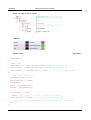
2.2. Conventions
1. Direct modifcation in memory:
Functions, which modify input values with pointer like _Array_Sort,
starts with an underscore "_". _Array_Sort sorts an array directly in
memory, which has the signifcant advantage that a very large array
may not be passed to the function and therefore memory of the size
of the array and the time is saved for copying. However, it is only recommended for experienced users to use these functions, as a misuse may lead to serious errors and crashes! In the application of
functions that begin with "_", special care is appropriate and in particular to ensure that the call parameters never accept undefned values.
2. Naming of functions:
Function modules with timing manner, such as the function PT1 are
described by naming FT_<modulname> (ie. FT_PT1). Functions without a time reference are indicated with F_<modulename>.
3. Logical equations:
Within this guide, the logical links are used & for AND , + for OR, /A
for negated A and # for a XOR (exclusive OR).
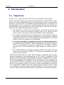
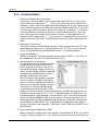
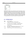
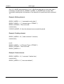
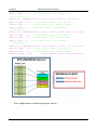
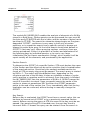
4. Setup values for modules:
To achieve that the application and
programming remains clear and
that complex functions can be represented simply, many of the modules of the library OSCAT have adjustable parameters that can be
edited in application by double-clicking on the graphic symbol
of the module. Double-clicking on
the icon opens a dialog box that allows you to edit the Setup values. If
a function is used multiple times,
so the setup values are set individually for each module. The processing by double-clicking works on
CoDeSys exclusively in CFC. In ST, all parameters, including the setup parameters may passed in the function call. The setup parameters are simply added to the normal inputs. The parameters are in
the graphical interface entered by double click and then processed
as constants under IEC61131. It should be noted that time values
has to be written with syntax "T#200ms" and TRUE and FALSE in capital letters.
5. Error and status Reporting (ESR):
More complex components are largely contributed a Error or status
output. A Error Output is 0 if no error occurs during the execution. If,
10
Version 1.21
Chapter 2.
Introduction
however, in a module a error occurs, this output takes a value in the
range 1 ..99 and reports a error with a error number. A status or Error Collection module may collect these messages and time-stamped, store them in a database or array, or by TCP/IP forward it to
higher level systems. An output of the type Status is compatible
with a Error starting with identical function. However, a status output reports not only errors but also leads on activities of the module
log. Values between 1..99 are still error messages. Between
100..199 are located the reports of state changes. The range from
200..255 is reserved for Debug Messages. With this, within the library OSCAT standard functionality, a simple and comprehensive option
is ofered to integrate operational messages and error messages in
a simple manner, without afecting the function of a system. Modules that support this procedure, as of revision 1.4 are marked "ESRready." For more information on ESR modules, see the section
"Other functions".
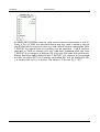
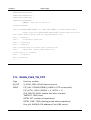
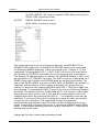
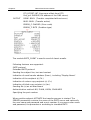
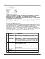
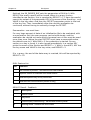
2.3. Test environment and conditions
Available platforms and related dependencies
CoDeSys:
Needs the libraries " SysLibFile.lib " and " SysLibSockets.lib "
Runs on
WAGO 750-841
CoDeSys SP PLCWinNT V2.4
and compatible platforms
PCWORX:
No additional library needed
Runs on all PLC iwith fle system and Ethernet controllers with frmware >=
3.5x
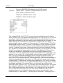
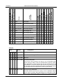
BECKHOFF:
Development Environment
11
Target
Platform
PLC libraries to include
Version 1.21
Chapter 2.
Introduction
TwinCAT v2.8.0 or higher
PC or CX
(x86)
TcSystem.Lib
TcBase.Lib
TcSystem.Lib
TwinCAT v2.10.0 Build >= 1301 or
higher
CX (ARM)
TcSystem.Lib
TcBase.Lib
TcSystem.Lib
Requires the installation of "TwinCAT TCP / IP Connection Server"
Thus needs the library "TcpIp.Lib "
(Standard.lib; TcBase.Lib; TcSystem.Lib is automatically included)
Programming environment:
NT4, W2K, XP, Xpe;
TwinCAT system version 2.8 or higher;
TwinCAT Installation Level: TwinCAT PLC or higher;
Target platform:
TwinCAT PLC runtime system version 2.8 or higher.
PC or CX (x86)
TwinCAT TCP/IP Connection Server v1.0.0.0 or higher;
NT4, W2K, XP, XPe, CE (image v1.75 or higher);
CX (ARM)
TwinCAT TCP/IP Connection Server v1.0.0.44 or higher;
CE (image V2.13 or later);
2.4. Releases
This manual is updated by OSCAT continuously. It is recommended to download the latest version of the OSCAT manual under www.OSCAT.DE . Here
the most current Manual is available for download. In addition to the Manual OSCAT prepared a detailed revision history. The OSCAT revisionhistory
lists all revisions of individual modules, with amendments and at what release the library of this component is included.
12
Version 1.21
Chapter 2.
Introduction
2.5. Support
Support
is
given
by
the
users
in
the
forum
WWW.OSCAT.DE. A claim for support does not exists, even if the library or
parts of the library are faulty. The support in the forum under the OSCAT is
provided for users voluntarily and with each other. Updates to the library
and documentation are usually made available once a month on the home
page of OSCAT under WWW.OSCAT.DE. A claim for maintenance, troubleshooting and software maintenance of any kind is generally not existing
from OSCAT. Please do not send support requests by email to OSCAT. Requests can be processed faster and more efectively when the inquiries
are made in our forum.
13
Version 1.21
Chapter 3.
Demo-Programs
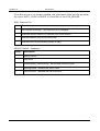
3. Demo-Programs
3.1. Demo programs
The OSCAT Network Library contains components and functions that deal
with the issue of fle-handling and ethernet communications, and sometimes require enhanced base knowledge . In order to allow the user easy
access are possible, for many theme demo programs are prepared.
The demo programs are in network.lib in the folder "DEMO" included. If
they are used, the needed programs should be copied to your project and
then can be adjusted to your needs. Some modules require the disclosure
of its own specifc parameters so that they are fully functional.
The Codesys and Beckhof library demo programs are hidden because
they would otherwise occupy resources needlessly.
BASE64_DEMO
CSV_PARSER_BUF_DEMO
CSV_PARSER_FILE_DEMO
DLOG_FILE_CSV
DLOG_FILE_CSV_FTP_DEMO
DLOG_FILE_CSV_SMTP_DEMO
DLOG_FILE_HTML_DEMO
DLOG_FILE_XML_DEMO
DLOG_RRD_DEMO
DNS_DYN_DEMO
DNS_REV_DEMO
DNS_SNTP_SYSLOG_DEMO
FILE_BLOCK_DEMO
FTP_CLIENT_DEMO
GET_WAN_IP_DEMO
HTTP_DEMO
INI_PARSER_BUF_DEMO
INI_PARSER_FILE_DEMO
IP2GEO_DEMO
IRTRANS_DEMO
14
Version 1.21
Chapter 3.
Demo-Programs
MB_CLIENT_DEMO
MB_SERVER_DEMO
MD5_CRAM_AUTH_DEMO
NET_VAR_MASTER_DEMO
NET_VAR_SLAVE_DEMO
RC4_CRYPT_DEMO
SHA_MD5_DEMO
SMTP_CLIENT_DEMO
SPIDER_DEMO
TELNET_LOG_DEMO
TELNET_PRINT_DEMO
TN_VISION_DEMO_1
TN_VISION_DEMO_2
YAHOO_WEATHER_DEMO
WORLD_WEATHER_DEMO
15
Version 1.21
Chapter 4.
Data Types of the NETWORK-Library
4. Data Types of the NETWORK-Library
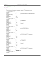
4.1. DLOG_DATA
The Structure DLOG_DATA is used for communication of the DLOG_ * modules.
DLOG_DATA:
Data field
Data Type
Description
STORE_TYPE
BYTE
Typ of DLOG_STORE module
ADD_HEADER
BOOL
Header data store
ADD_DATA
BOOL
Cyclic data store
ADD_DATA_REQ
BOOL
Store data from external
CLOCK_TRIG
BOOL
DTI ( Date-Time ) New value
ID_MAX
USINT
Number of blocks DLOG_* modules
DTI
DT
current Date-Time Value
UCB
UNI_CIRCULAR_BUFFER_DATA
Data Storage
NEW_FILE_STRING
STRING
New file name
NEW_FILE_RTRIG
BOOL
Edge new file was created
4.2. us_LOG_VIEWPORT
us_LOG_VIEWPORT
16
Name
Type
Properties
LINE_ARRAY
ARRAY [1..40] OF INT
LOG-index references
COUNT
INT
Number of visible messages
UPDATE_COUNT
UINT
Update count
MOVE_TO_X
INT
Control of the message display
UPDATE
BOOL
Data has been changed -> redraw
Version 1.21
Chapter 4.
Data Types of the NETWORK-Library
4.3. URL
The Structure URL stores the individual parts of a URL.
URL:
Data field
Data Type
Description
PROTOCOL
STRING (10)
Protocol
USER
STRING(32)
User Name
PASSWORD
STRING(32)
Passwort
DOMAIN
STRING(80)
Domain
PORT
WORD
Port Nummer
PATH
STRING(80)
Pfadangabe
QUERY
STRING(120)
Query
ANCHOR
STRING (40)
Anker
HEADER
STRING(160)
Header
4.4. us_TN_INPUT_CONTROL
A variable of type us_TN_INPUT_CONTROL can be used to parameterize
and manage various INPUT_CONTROL elements, and as well as to represent the ToolTip information.
us_TN_INPUT_CONTROL:
17
Data field
Data Type
Description
bo_Enable
BOOL
Processing enable / disable
bo_Update_all
BOOL
All elements redraw
bo_Reset_Fokus
BOOL
set Focus on frst Element
in_Fokus_at
INT
Element with an active focus
in_Count
INT
Number of INPUT_CONTROL elements
Version 1.21
Chapter 4.
Data Types of the NETWORK-Library
in_ToolTip_X
INT
ToolTip Text X Ofset
in_ToolTip_Y
INT
ToolTip Text Y Ofset
by_ToolTip_Attr
BYTE
ToolTip text attributes (color)
in_ToolTip_Size
INT
ToolTip text length
usa_TN_INPUT_C ARRAY [1..20] OF
ONTROL_DATA
us_TN_INPUT_CONTROL_DATA
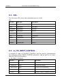
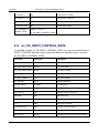
4.5. us_TN_INPUT_CONTROL_DATA
A variable of type us_TN_INPUT_CONTROL_DATA can use to parameterize a
INPUT_CONTROL element and to process element related inputs / events.
us_TN_INPUT_CONTROL_DATA:
18
Data field
Data Type
Description
by_Input_Exten_Code
BYTE
Extended Key Code
by_Input_ASCII_Code
BYTE
Key Code ASCII
bo_Input_ASCII_IsNum
BOOL
Key code is a digit
in_Title_X_Offset
INT
Title Text X Offset
in_Title_Y_Offset
INT
Title Text Y Offset
by_Title_Attr
BYTE
Title text attributes
st_Title_String
STRING
st_Title_String
in_Cursor_X
INT
current cursor X position
in_Cursor_Y
INT
current cursor Y position
IN_TYPE
INT
Element Type
in_X
INT
Element X position
in_Y
INT
Element Y position
in_Cursor_Pos
INT
current cursor position
by_Attr_mF
BYTE
Attributes for element with focus
by_Attr_oF
BYTE
Attributes for element without focus
Version 1.21
Chapter 4.
Data Types of the NETWORK-Library
in_selected
INT
Text element is selected
st_Input_Mask
STRING
Input mask
st_Input_Data
STRING(STRING_LENGTH) Text input current
st_Input_String
STRING
text copy after entering
st_Input_ToolTip
STRING
Text for ToolTip
in_Input_Option
INT
Text Options
bo_Input_Entered
BOOL
Text RETURN key pass
bo_Input_Hidden
BOOL
Text hidden input with '*'
bo_Input_Only_Num
BOOL
Text only allow number entry
bo_Focus
BOOL
Element has focus
bo_Update_Input
BOOL
Element due to input redraw
bo_Update_All
BOOL
Element draw from scratch
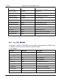
4.6. us_TN_MENU
A variable of type us_TN_MENU can be used to parameterize a MENU item,
to display it and to process element related inputs.
us_TN_MENU:
19
Data field
Data Type
Description
st_Menu_Text
STRING(STRING_LENGTH)
Menu items
in_Menu_E_Count
INT
Number of menu items
in_Y
INT
Menu Y position
in_X
INT
Menu X position
by_Attr_mF
BYTE
Text attributes with focus
by_Attr_oF
BYTE
Text attributes without focus
in_X_SM_new
INT
Sub-menu, new X-position
in_Y_SM_new
INT
Sub-menu, new Y-position
in_X_SM_old
INT
Sub-menu old X-Position
Version 1.21
Chapter 4.
Data Types of the NETWORK-Library
in_Y_SM_old
INT
Sub-menu old Y position
in_Cur_Menu_Item
INT
current main menu item
in_Cur_Sub_Item
INT
current sub-menu item
in_State
INT
menu status
in_Menu_Selected
INT
selected menu item
Menu, number of lines BOOL
action: create menu
bo_Destroy
BOOL
action: remove menu
bo_Update
BOOL
action: refresh menu
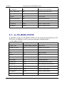
4.7. us_TN_MENU_POPUP
A variable of type us_TN_MENU_POPUP can be used to parameterize a POPUP item, to display it and to process element related inputs.
us_TN_MENU_POPUP:
20
Data field
Data Type
Description
st_Menu_Text
STRING(STRING_LENGTH)
Menu items
in_Menu_E_Count
INT
Number of menu items
in_X
INT
Menu X position
in_Y
INT
Menu Y position
in_Cols
INT
INT
INT
INT
Menu, number of lines
in_Cur_Item
INT
Current menu item
by_Attr_mF
BYTE
Text attributes with focus
by_Attr_oF
BYTE
Text attributes without focus
by_Input_Exten_Code
BYTE
keycode - special keys
Menu, number of lines
BOOL
action: create menu
bo_Destroy
BOOL
action: remove menu
bo_Update
BOOL
action: refresh menu
Version 1.21
Chapter 4.
bo_Activ
Data Types of the NETWORK-Library
BOOL
Menu is active
4.8. us_TN_SCREEN
A variable of type us_TN_SCREEN can be used to manage display the graphical user interface (GUI).
us_TN_SCREEN:
21
Data field
Data Type
Description
bya_CHAR
ARRAY [0..1919] OF BYTE
Screen character
bya_COLOR
ARRAY [0..1919] OF BYTE
screen color codes
bya_BACKUP
ARRAY [0..1919] OF BYTE
screen backup memory
bya_Line_Update
ARRAY [0..23] OF BYTE
screen lines update
by_Input_Exten_Code
BYTE
Key code special keys
by_Input_ASCII_Code
BYTE
Key Code ASCII
bo_Input_ASCII_IsNum
BOOL
Key code is a digit
in_Page_Number
INT
current page number
in_Cursor_X
INT
Cursor X Position
in_Cursor_Y
INT
Cursor Y Position
in_EOS_Ofset
INT
End of String Ofset
by_Clear_Screen_Attr
BYTE
screen delete color
bo_Clear_Screen_Attr
BOOL
delete screen
bo_Modul_Dialog
BOOL
modal dialog active
bo_Menu_Bar_Dialog
BOOL
Menu dialog active
Version 1.21
Chapter 4.
Data Types of the NETWORK-Library
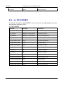
4.9. FILE_PATH_DATA
The Structure FILE_PATH_DATA is used by the the module FILE_PATH_SPLIT
to store each item.
FILE_PATH_DATA:
Data field
Data Type
Description
DRIVE
STRING (3)
Drive Name
DIRECTORY
STRING(STRING_LENGTH)
Directory Name
FILE NAME
STRING
File Name
4.10. FILE_SERVER_DATA
FILE_SERVER data structure:
Name
Type
Properties
File_open
BOOL
File is open
FILE NAME
STRING
File Name
MODE
BYTE
Mode - command
OFFSET
UDINT
File offset for reading and writing
FILE_SIZE
UDINT
Current size of the file in bytes
AUTO_CLOSE
TIME
Timing for the automatic closure
ERROR
BYTE
Error codes (system dependent)
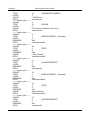
4.11. IP2GEO
IP2GEO data structure:
Name
22
Type
Properties
STATE
BOOL
Data is valid
Data is valid
DWORD
IP address of the geographical data
Version 1.21
Chapter 4.
Data Types of the NETWORK-Library
COUNTRY_CODE
STRING(2)
Country code (ISO format) eg AT = Austria
COUNTY_NAME
STRING(20)
Name of the country
REGION_CODE
STRING(2)
Region Code (FIPS format) eg 09 = Vienna
REGION_NAME
STRING(20)
Name of region
CITY
STRING(20)
Name of the city
GEO_LATITUDE
REAL
Latitude of the place
GEO_LONGITUDE
REAL
Longitude of the place
TIME_ZONE_NAME
STRING(20)
Time zone name
GMT_OFFSET
INT
Offset from Universal Time in minutes
IS_DST
BOOL
DST active
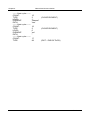
4.12. IP_C
IP_C data structure:
Data field
Data Type
Description
C_MODE
BYTE
Type of connection
C_PORT
WORD
Port Number
C_IP
DWORD
coded IP v4 address
C_STATE
BYTE
Status of the connection
C_ENABLE
BOOL
Connection release
R_OBSERVE
BOOL
Receive data monitor
TIME_RESET
BOOL
Reset the monitoring times
ERROR
DWORD
Error Code
FIFO
IP_FIFO_DATA
Data structure of the access management
(No user access required)
MAILBOX
23
ARRAY [1..16] OF BYTE
Mailbox: data area for module data exchange
Version 1.21
Chapter 4.
Data Types of the NETWORK-Library
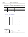
4.13. IP_FIFO_DATA
IP_FIFO_DATA data structure:
Data field
Data Type
Description
X
ARRAY [1..128] OF BYTE
FIFO memory with registered ID's
Y
ARRAY [1..128] OF BYTE
Number of entries per ID's
ID
BYTE
Last assigned ID (highest ID)
MAX_ID
BYTE
Maximum number of applications per ID
INIT
BOOL
Initialization performed
EMPTY
BOOL
FIFO is empty
FULL
BOOL
FIFO is full (should not happen!)
TOP
INT
Maximum number of entries in FIFO
NW
INT
write-index FIFO
NR
INT
read-index FIFO
4.14. LOG_CONTROL
us_LOG_VIEWPORT data structure:
24
Name
Type
Properties
NEW_MSG
STRING(STRING_LENGTH)
New Message - Text
NEW_MSG_OPTION
DWORD
New message - Option
BYTE 3: Reserve
BYTE 2: Level
BYTE 1: Backcolor
BYTE 0: Frontcolor
LEVEL
BYTE
Given log level
SIZE
INT
Size of the array (maximum index)
RESET
BOOL
Reset / delete the entries
PRINTF
ARRAY[1.11] OF
STRING(STRING_LENGTH)
Parameter data for PRINT_SF block
MSG
ARRAY[0.N] OF
Array for message - text
Version 1.21
Chapter 4.
Data Types of the NETWORK-Library
STRING(STRING_LENGTH)
MSG_OPTION
ARRAY[0.N] OF DWORD
Array ofor messages - Option
BYTE 3: Reserve
BYTE 2: Level
BYTE 1: Back Color
BYTE 0: Color front
UPDATE_COUNT
UINT
Update-counter (increased with each new
message)
IDX
INT
Current Issue Index
RING_MODE
BOOL
BUFFER enabled overflow / Ringmode enabled
4.15. NET_VAR_DATA
NET_VAR data structure:
Name
Type
Properties
CYCLE
UDINT
Cycle Counter
STATE
BYTE
Operating condition
INDEX
INT
Read / write index
ID_MAX
USINT
Number of satellite components
Error_id
BYTE
ID number of the faulty module
BUF_SIZE
UINT
Size of the buffer (bytes)
S_BUF
NETWORK_BUFFER
Network buffer for sending data
R_BUF
NETWORK_BUFFER
Network buffers for receiving data
4.16. PRINTF_DATA
PRINTF_DATA data structure:
Data field
25
Data Type
Description
Version 1.21
Chapter 4.
PRINTF
Data Types of the NETWORK-Library
ARRAY [1..11] OF STRING(LOG_SIZE)
Array for passing parameters
4.17. UNI_CIRCULAR_BUFFER_DATA
The Structure UNI_CIRCULAR_BUFFER_DATA is used for data management
for the module UNI_CIRCULAR_BUFFER
UNI_CIRCULAR_BUFFER_DATA:
Data field
Data Type
Description
D_MODE
INT
MODE (command number)
D_HEAD
WORD
Header information Read / Write
D_STRING
STRING(STRING_LENGTH)
STRING Read / Write
D_REAL
REAL
REAL Read / Write
D_DWORD
DWORD
DWORD Read / Write
BUF_SIZE
UINT
Number of bytes in the buffer
BUF_COUNT
UINT
Number of elements in the buffer
BUF_USED
USINT
Level (0-100%)
BUF
NW_BUF_LONG
Data BUFFER
_GetStart
UINT
Internal: read pointer
_GetEnd
UINT
Internal: read pointer
_Last
UINT
Intern: Data pointer
_First
UINT
Intern: Data pointer
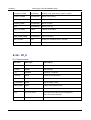
4.18. VMAP_DATA
VMAP_DATA data structure:
26
Name
Type
Properties
FC
DWORD
function code: release bit mask
Version 1.21
Chapter 4.
Data Types of the NETWORK-Library
V_ADR
INT
Virtual Address Range: Start address
V_SIZE
INT
Virtual address space: number of WORD
P_ADR
INT
Real address space: Start address
TIME_OUT
TIME
Watchdog
4.19. XML_CONTROL
XML_CONTROL data structure:
Data field
27
Data Type
Description
COMMAND
WORD
Control commands (binary occupancy)
START_POS
UINT
(Buffer index of first character)
STOP_POS
UINT
(Buffer-index of the last characters)
COUNT
UINT
Element number
TYPE
INT
Type code of the current element
LEVEL
UINT
Current hierarchy / level
PATH
STRING(STRING_LENGTH)
Hierarchy as TEXT (PATH)
ELEMENT
STRING(STRING_LENGTH)
current item as TEXT
ATTRIBUTE
STRING(STRING_LENGTH)
Current attributes as TEXT
VALUE
STRING(STRING_LENGTH)
Current value as TEXT
BLOCK1_START
UINT
Start position of block 1
BLOCK1_STOP
UINT
Stop position of Unit 1
BLOCK2_START
UINT
Start position of block 2
BLOCK2_STOP
UINT
Stop position of Unit 2
Version 1.21
Chapter 4.
Data Types of the NETWORK-Library
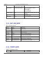
4.20. WORLD_WEATHER_DATA
WORLD_WEATHER_DATA data structure:
Name
Type
Properties
CUR
WORLD_WEATHER_CUR
Current weather conditions
DAY
ARRAY [0..4] OF WORLD_WEATHER_DAY
Next 5 days of weather forecast
WORLD_WEATHER_CUR data structure:
Name
Type
Properties
OBSERVATION_TIME
STRING(8)
Observation time (UTC)
TEMP_C
INT
Temperature (°C)
WEATHER_CODE
INT
Unique Weather Code
WEATHER_DESC
STRING(60)
Weather description text
WEATHER_ICON
INT
Weather Icon
WIND_SPEED_MILES
INT
Wind speed in miles per hour
WIND_SPEED_KMPH
INT
Wind speed in kilometre per hour
WIND_DIR_DEGREE
INT
Wind direction in degree
WIND_DIR16POINT
STRING (3)
16-Point wind direction compass
PRECIPMM
REAL
Precipitation amount in millimetre
HUMIDITY
INT
Humidity (%)
VISIBILITY
INT
Visibility (km)
PRESSURE
INT
Atmospheric pressure in milibars
CLOUDOVER
INT
Cloud cover (%)
WORLD_WEATHER_DAY data structure:
28
Name
Type
Properties
DATE_OF_DAY
STRING (10) Date for which the weather is forecasted
Version 1.21
Chapter 4.
Data Types of the NETWORK-Library
TEMP_MAX_C
INT
Day temperature in °C(Celcius)
TEMP_MAX_F
INT
Day temperature in °F(Fahrenheit)
TEMP_MIN_C
INT
Night temperature in °C(Celcius)
TEMP_MIN_F
INT
Night temperature in °F(Fahrenheit)
WIND_SPEED_MILES
INT
Wind Speed in mph (miles per hour)
WIND_SPEED_KMPH
INT
Wind Speed in kmph (Kilometer per hour)
WIND_DIR_DEGREE
INT
Wind direction in degree
WIND_DIR16POINT
STRING (3)
16-Point wind direction compass
WEATHER_CODE
INT
A unique weather condition code
WEATHER_DESC
STRING(60)
Weather description text
WEATHER_ICON
INT
Weather Icon
PRECIPMM
REAL
Precipitation Amount (millimetre)
4.21. YAHOO_WEATHER_DATA
YAHOO_WEATHER data structure:
29
Name
Type
Properties
TimeToLive
INT
Time to Live: how long in minutes this feed should be
cached
location_city
STRING
(40)
The location of this forecast: city: city name
location_region
STRING(20) The location of this forecast: region: state, territory, or
region, if given
location_country
STRING(20) The location of this forecast: country:
unit_temperature
STRING (1) temperature: degree units, for f c for Celsius Fahrenheit
or
Version 1.21
Chapter 4.
30
Data Types of the NETWORK-Library
unit_distance
STRING(2)
distance: distance units for MI for miles or km for kilometers
unit_pressure
STRING(2)
pressure: barometric pressure units of, for in pounds
per square inch or mb for milli bars
unit_speed
STRING (3) speed: units of speed, mph for miles per hour or kilometers per hour for kph
wind_chill
INT
Forecast information about wind chill in degrees
wind_direction
INT
Forecast information about wind direction in degrees
wind_speed
REAL
Forecast information about wind speed, in the units
(mph or kph)
atmosphere_humidity
INT
Forecast information about current atmospheric humidity: humidity, in percent
atmosphere_pressure
INT
Forecast information about current atmospheric pressure: barometric pressure, in the units (in or mb)
atmosphere_visibility
REAL
Forecast information about current atmospheric visibility, in the units (mi or km)
atmosphere_rising
INT
Forecast Information about rising: state of the barometric pressure: Steady (0), rising (1), or falling (2). (Integer: 0, 1, 2)
astronomy_sunrise
STRING
(10)
sunrise: today's sunrise time. The time is a string in a local time format of "h: mm am / pm"
astronomy_sunset
STRING
(10)
sunset: today's sunset time. The time is a string in a loc
al time format of "h: mm am / pm"
geo_latitude
REAL
The latitude of the location
geo_longitude
REAL
The longitude of the location
cur_conditions_temp
INT
cur_conditions_text
cur_conditions_text
STRING
(40)
The current weather conditions: text: a textual description of conditions
cur_conditions_code
INT
The current weather conditions: code: the code for this
condition forecast
cur_conditions_icon
INT
The current weather conditions: icon: the condition icon
for this forecast
forcast_today_low_temp
INT
The weather conditions today forcast: the forecasted
low temperature for this day in the units (f or c)
forcast_today_high_temp
INT
The forcast today weather conditions: the forecasted
high temperature for this in the day units (f or c)
forcast_today_text
STRING
The forcast today weather conditions: text: a textual de-
Version 1.21
Chapter 4.
Data Types of the NETWORK-Library
(40)
scription of conditions
forcast_today_code
INT
The current weather conditions: code: the code for this
condition forecast
forcast_today_icon
INT
The current weather conditions: icon: the icon condition
for this forecast
forcast_tomorrow_low_temp
INT
The forcast tomorrow weather conditions: the forecasted low temperature for this day in the units (f or c)
forcast_tomorrow_high_temp INT
The forcast tomorrow weather conditions: the forecasted high temperature for this day in the units (f or c)
forcast_tomorrow_text
STRING
(40)
The forcast tomorrow weather conditions: text: a textual
description of conditions
forcast_tomorrow_code
INT
The current weather conditions: code: the code for this
condition forecast
forcast_tomorrow_icon
INT
The current weather conditions: icon: the icon condition
for this forecast
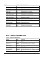
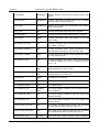
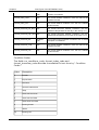
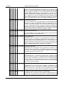
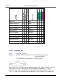
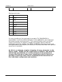
Condition Codes:
The felds cur_conditions_code, forcast_today_code and
forcast_tomorrow_code describe the weather in text form by " Condition
Codes "
31
Value
Description
0
tornado
1
tropical storm
2
hurricane
3
severe thunderstorms
4
Temp
5
mixed rain and snow
6
mixed rain and sleet
7
mixed snow and sleet
8
freezing drizzle
9
drizzle
10
freezing rain
Version 1.21
Chapter 4.
32
Data Types of the NETWORK-Library
11
showers
12
showers
13
Snow Flurries
14
Light snow showers
15
blowing snow
16
snow
17
hail
18
sleet
19
20
20
foggy
21
haze
22
smoky
23
blustery
24
windy
25
cold
26
cloudy
27
mostly cloudy (night)
28
mostly cloudy (day)
29
partly cloudy (night)
30
partly cloudy (day)
31
clear (night)
32
sunny
33
fair (night)
34
fair (day)
35
mixed rain and hail
36
hot
37
isolated thunderstorms
38
scattered thunderstorms
Version 1.21
Chapter 4.
33
Data Types of the NETWORK-Library
39
scattered thunderstorms
40
scattered showers
41
heavy snow
42
scattered snow showers
43
heavy snow
44
mostly cloudy
45
46
46
snow showers
47
isolated thundershowers
3200
not available
Version 1.21
Chapter 5.
Other Functions
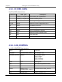
5. Other Functions
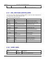
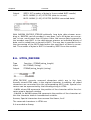
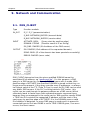
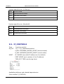
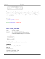
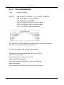
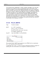
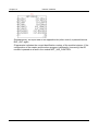
5.1. ELEMENT_COUNT
Type
Function: INT
Input
SEP: BYTE (separation character of the elements)
I/O
ELEMENT: STRING(ELEMENT_LENGTH) (input list)
Output
INT (number of items in the list)
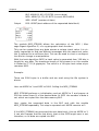
ELEMENT_COUNT determines the number of items in a list.
If the parameter ELEMENT is an empty string 0 is passed as result. If at
least one character is in ELEMENT it is evaluated as a single element and
ELEMENT_COUNT = 1 is passed to output.
Examples:
ELEMENT_COUNT('0,1,2,3',44) = 4
ELEMENT_COUNT('',44) = 0
ELEMENT_COUNT('x',44) = 1
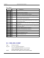
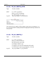
5.2. ELEMENT_GET
Type
Function: STRING(ELEMENT_LENGTH)
Input
SEP: BYTE (separation character of the elements)
POS: INT (of the item)
34
I/O
ELEMENT: STRING(ELEMENT_LENGTH) (input list)
Output
STRING (String output)
Version 1.21
Chapter 5.
Other Functions
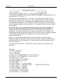
ELEMENT_GET passes the item at the position POS from a list. The list consists of strings which are separated by the separation character SEP. The
frst element of the list has the position 0
Examples:
ELEMENT_GET('ABC,23,,NEXT', 44, 0) = 'ABC'
ELEMENT_GET('ABC,23,,NEXT', 44, 1) = '23'
ELEMENT_GET('ABC,23,,NEXT', 44, 2) = ''
ELEMENT_GET('ABC,23,,NEXT', 44, 3) = 'NEXT'
ELEMENT_GET('ABC,23,,NEXT', 44, 4) = ''
ELEMENT_GET('', 44, 0) = ''
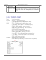
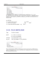
5.3. NETWORK_VERSION
Type
Function: DWORD
Input
IN : BOOL (if TRUE the module provides the release date)
Output
(Version of the library)
NETWORK_VERSION provides if IN = FALSE the current version number as
DWORD. If IN is set to TRUE then the release date of the current version as
a DWORD is returned.
Example:
NETWORK_VERSION(FALSE) = 111 for version 1.11
DWORD_TO_DATE(NETWORK_VERSION(TRUE)) = 2011-2-3
35
Version 1.21
Chapter 6.
Device Driver
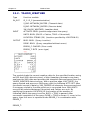
6. Device Driver
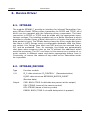
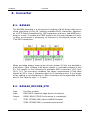
6.1. IRTRANS
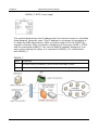
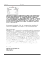
The module IRTRANS_? provide an interface for infrared Transmitter Company IRTrans GmbH. IRTrans ofers transmitter for RS232 and TCP/IP, all of
which can be operated with the following driver components. The basic
connection to RS232 or TCP/IP must be made with the appropriate manufacturer routines. The interface modules rely on a Bufer Interface to which
provides in a Bufer (Array of Byte) data and in a Counter the length of the
data packet in bytes. The IRTrans devices learn the IR key codes and translate them in ASCII Strings using a confgurable database. With the Ethernet variant, this Strings then sent over UDP and can be received from a
PLC and be evaluated. Thus, for example, the blinds are automatically
shut down when someone turns on the TV without this additional action
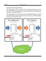
would be necessary. The PLC can listen in this manner any number of re mote controls in diferent areas and derive appropriate actions from it.
Conversely, of course, the release of key codes on the Transmitter modules is possible.
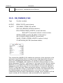
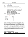
6.2. IRTRANS_DECODE
Type
Function module
I/O
IP_C: data structure 'IP_CONTROL ' (Parameterization)
R_BUF: data structure NETWORK_BUFFER_SHORT '
(Receive data)
Output
CMD: BOOL (TRUE if valid data are present at the output)
DEV: STRING (name of the remote control)
KEY: STRING (name of the key codes)
ERROR: BOOL (TRUE if a invalid data packet is present)
36
Version 1.21
Chapter 6.
Device Driver
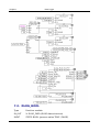
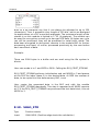
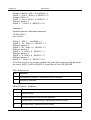
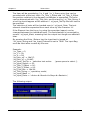
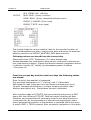
IRTRANS_DECODE receives the data from the module IRTRANS_SERVER
present in BUFFER, checks if a valid data package is available and decodes the name of the remote control and the name of the button form the
data packet. If a valid data packet has been decoded, the name of the remote control is passed at the output DEV and the name of the button on
the output KEY. The output CMD signals that the new output data are present. The ERROR output is then set when a data packet was received that
is not in the correct format.
The format is defned as follows:
'Name of the remote control', 'Name of the key code' $R$N
A data packet consists of the name of the remote control, followed by a
comma and then the name of the key codes. The data packet is a completed by Carriage Return and a Line Feed .
To ensure that IRTRANS_DECODE works in the IRTrans confguration the
Check box BROADCAST IR RELAY must be checked and in the corresponding Device database under the DEFAULT ACTION the String '%r%c\r\n'
must be registered. IRTRANS_DECODE evaluates just this String and decodes %r as the name and %c as pressed a button of the remote control.
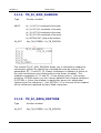
6.3. IRTRANS_RCV_1
Type
Input
I/O
Function module
CMD : BOOL (TRUE if data for evaluating are available)
DEV: STRING (name of the remote control)
KEY: string (name of button)
Setup
DEV_CODE: STRING (to be decoded remote control name)
KEY_CODE: STRING (key code to be decoded)
Output
Q: BOOL (output)
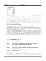
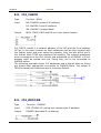
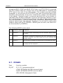
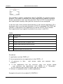
IRTRANS_RCV_1 checkes when CMD = TRUE if the string matches the input
DEV corresponds to DEV_CODE (device code) and the string at the input
37
Version 1.21
Chapter 6.
Device Driver
KEY corresponds to the KEY_CODE. If the codes match and CMD = TRUE,
then the output Q for a cycle is set to TRUE.
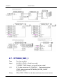
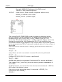
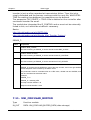
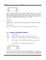
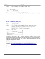
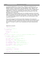
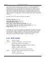
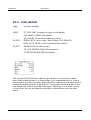
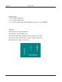
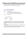
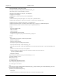
The following example shows the application of IRTRANS_RCV_1:
In this example, the receive data bufer to IRTRANS_DECODE is passed.
The decoder determines from the valid data packets String DEV and KEY
and
passes
them
with
CMD
to
IRTRANS_RCV_1 .
IRTRANS_RCV_1 or alternatively IRTRANS_RCV_4 and IRTRANS_RCV_ checks
whether DEV and KEY match and then switches the output Q for a cycle to
TRUE. in the example a DRIVER_1 is controlled which enables the remote
control to switch the output with each received log.
If multiple Key Codes are to be evaluated alternatively the modules IRTRANS_RCV_4 or IRTRANS_RCV_8 can be used or more of these modules
can be used in parallel mode.
38
Version 1.21
Chapter 6.
Device Driver
6.4. IRTRANS_RCV_4
Type
Function module
Input
CMD: BOOL (TRUE if data for evaluating are available)
I/O
DEV: STRING (name of the remote control)
KEY: string (name of button)
Setup
DEV_CODE: STRING (to be decoded remote control name)
KEY_CODE_0..3: STRING (key code to be decoded)
Output
Q0..Q3: BOOL (output)
IRTRANS_RCV_4 checkes when CMD = TRUE if the string matches the input
DEV corresponds to DEV_CODE (device code) and the string at the input
KEY corresponds to the KEY_CODE. If the codes match and CMD = TRUE,
then the output Q for a cycle is set to TRUE. For more information about
the function of the device are under IRTRANS_RCV_1.
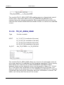
6.5. IRTRANS_RCV_8
Type
Input
I/O
Function module
CMD : BOOL (TRUE if data for evaluating are available)
DEV: STRING (name of the remote control)
KEY: string (name of button)
Setup
DEV_CODE: STRING (to be decoded remote control name)
KEY_CODE_0..7: STRING (key code to be decoded)
Output
Q0..Q7: BOOL (output)
IRTRANS_RCV_8 checkes when CMD = TRUE if the string matches the input
DEV corresponds to DEV_CODE (device code) and the string at the input
KEY corresponds to the KEY_CODE. If the codes match and CMD = TRUE,
39
Version 1.21
Chapter 6.
Device Driver
then the
output Q for a cycle is set
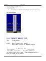
6.6.
IRTRANS_SERVER
to TRUE. For more information about
the function of the device are under IRTRANS_RCV_1.
Type
Function module
Input
UDP_TCP : BOOL (FALSE = UDP / TRUE = TCP)
In_Out
IP_C: data structure 'IP_CONTROL ' (Parameterization)
S_BUF: data structure 'NETWORK_BUFFER_SHORT'
(Transmit data)
R_BUF: data structure NETWORK_BUFFER_SHORT '
(Receive data)
Output
S_ENABLE: BOOL (release IRTRANS data send)
R_ENABLE: BOOL (IRTRANS data receive enabled)
ERROR: DWORD (Error code: Check IP_CONTROL)
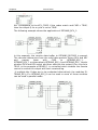
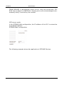
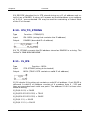
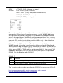
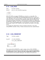
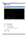
IRTRANS_SERVER can be used as both a receiver and a transmitter of IRTRANS commands. Is UDP_TCP = TRUE is a passive TCP connection, otherwise set up a passive UDP connection. The type of operation must also be
confgured with IRTRANS device. Once a data connection is available and
sending commands is allowed, S_ENABLE = TRUE. In UDP mode, after the
initial data received from IRTRANS, data can be sent, since in the passive
mode, the UDP-IP parameter is initially not known. The receiving mode is
indicated with R_ENABLE. If data are received they are available in R_BUF
for further processing for other modules. Send data has to be entered by
the modules in the S_BUF, so they are then sent automatically from IR40
Version 1.21
Chapter 6.
Device Driver
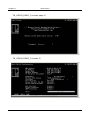
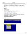
TRANS_SERVER. If transmission errors occurs, they are issued with "ERROR" (see module IP_CONTROL2). Existing errors are acknowledged automatically every 5 seconds by the module.
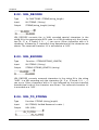
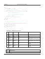
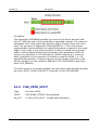
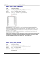
UDP server mode:
In the IRTRANS Web confguration, the IP address of the PLC is entered as
a broadcast address.
IRTRANS Web Confguration:
The following example shows the application of IRTRANS Devices
41
Version 1.21
Chapter 6.
Device Driver
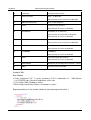
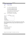
6.7. IRTRANS_SND_1
Type
Function module
Input
IN: BOOL (TRUE = Send key code)
T_REPEAT: TIME (time to re-send the key code)
I/O
IP_C: data structure 'IP_CONTROL ' (Parameterization)
S_BUF: data structure 'NETWORK_BUFFER_SHORT'
(Transmit data)
Setup
42
DEV_CODE: STRING (to be decoded remote control name)
Version 1.21
Chapter 6.
Device Driver
KEY_CODE: STRING (key code to be decoded)
Output
KEY: BYTE (output of the currently active key codes)
IRTRANS_SND_1 allows you to send a remote command to the IRTrans. If IN
TRUE the specifed device and key code in setup is sent to the IRTrans
which outputs in turn as a real remote control commands. With T_REPEAT
the repeat time for sending can be specifed . If IN remains constant to
TRUE so always this key code sent repeated after the time T_REPEAT. At
output KEY in active control "1" is passed. KEY = 0 means that the IN is
not active.
6.8. IRTRANS_SND_4
Type
Function module
Input
IN_0..3 : BOOL (TRUE = Send keycode x)
T_REPEAT: TIME (time to re-send the key code)
I/O
IP_C: data structure 'IP_CONTROL ' (Parameterization)
S_BUF: data structure 'NETWORK_BUFFER_SHORT'
(Transmit data)
Setup
DEV_CODE: STRING (to be decoded remote control name)
KEY_CODE_0..3: STRING (key code to be sent)
Output
43
KEY: BYTE (output of the currently active key codes)
Version 1.21
Chapter 6.
Device Driver
IRTRANS_SND_4 allows users to send remote control commands to the IRTrans. If IN_x is TRUE the specifed device and key code in setup is sent to
the IRTrans which outputs in turn as a real remote control commands. With
T_REPEAT the repeat time for sending can be specifed . If IN_0 remains
constant to TRUE so always this key code sent repeated after the time
T_REPEAT. If a change to a diferent IN_x occures this code will send immediately and then again delayed with T_REPEAT, if it remains a long period
of time. At output KEY the currently controlled KEY will be displayed. KEY
= 0 means that no IN_x is active. The values 1-3 are the IN_0 - IN_3.
6.9. IRTRANS_SND_8
Type
Function module
Input
IN_0..7 : BOOL (TRUE = Send keycode x)
T_REPEAT: TIME (time to re-send the key code)
I/O
IP_C: data structure 'IP_CONTROL ' (Parameterization)
S_BUF: data structure 'NETWORK_BUFFER_SHORT'
(Transmit data)
Setup
DEV_CODE: STRING (to be decoded remote control name)
KEY_CODE_0..7: STRING (key code to be sent)
Output
44
KEY: BYTE (output of the currently active key codes)
Version 1.21
Chapter 6.
Device Driver
IRTRANS_SND_8 allows users to send remote control commands to the IRTrans. If IN_x is TRUE the specifed device and key code in setup is sent to
the IRTrans which outputs in turn as a real remote control commands. With
T_REPEAT the repeat time for sending can be specifed . If IN_0 remains
constant to TRUE so always this key code sent repeated after the time
T_REPEAT. If a change to a diferent IN_x occures this code will send immediately and then again delayed with T_REPEAT, if it remains a long period
of time. At output KEY the currently controlled KEY will be displayed. KEY
= 0 means that no IN_x is active. The values 1-3 are the IN_0 - IN_7.
45
Version 1.21
Chapter 7.
Data Logger
7. Data Logger
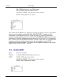
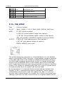
7.1. DATA-LOGGER
The data logger modules enable the collection and storage of process data
in real time. After triggering the storage pulse all parameterized process
values are stored in a data bufer, as various storage media are often not
fast enough. Up to 255 process values are processed in one package. The
calling order of the modules determines automatically the ranking of the
process values (take care of data-fow order)
Fore storing the various data types, the following modules are provided.
DLOG_STRING
DLOG_REAL
DLOG_DINT
DLOG_DT
DLOG_BOOL
Other data types convert frst manually, and transferred as STRING. The
collected data can then be forwarded to a data target.
DLOG_STORE_FILE_CSV
store data as csv-fle
DLOG_STORE_FILE_HTML
store data as HTML-fle
DLOG_STORE_FILE_XML
store data as XML-fle
DLOG_STORE_RRD
store data on RRD-server
The fles that are stored on the controller can then be forwarded to external data targets.
DLOG_FILE_TO_SMTP (File as Email)
DLOG_FILE_TO_FTP (copy fle to an external FTP server)
46
Version 1.21
Chapter 7.
Data Logger
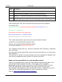
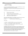
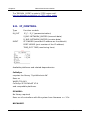
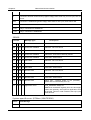
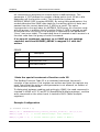
The modules above can be combined with each other.
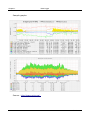
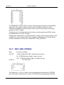
The following example shows the recording of a time stamp, a REAL and
DINT counter. Here, the process data is stored after each minute in a new
CSV formatted fle. Once a fle is ready, it will be moved automatically to
an FTP server.
47
Version 1.21
Chapter 7.
Data Logger
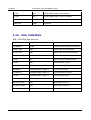
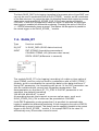
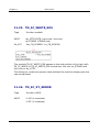
7.2. DLOG_BOOL
48
Type
Function module:
IN_OUT
X: DLOG_DATA (DLOG data structure)
INPUT
STATE: BOOL (process value TRUE / FALSE)
Version 1.21
Chapter 7.
Data Logger
ON: STRING (text for the TRUE state)
OFF: STRING (text for state FALSE)
COLUMN: STRING (40) (process value name)
DELTA: DINT (diference value)
The module DLOG_BOOL is for logging (recording) of a process value of type BOOL,
and can only be used in combination with a DLOG_STORE_* module, as this
coordinates of the data structure X to record the data. At recording formats that
support a process value name, such as at DLOG_STORE_FILE_CSV a name can be
provided at COLUMN". Depending on the state of the STATE the TEXT of parameter
OFF or ON is used. If with DELTA parameter a TRUE is specified, the automatic data
logging is enabled via differential monitoring. By changing the state of STATE
automatically a record is stored. This feature can be applied in parallel to the central
trigger on the DLOG_STORE_ * module.
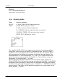
7.3. DLOG_DINT
Type
Function module:
IN_OUT
X: DLOG_DATA (DLOG data structure)
INPUT
VALUE: DINT (process value)
COLUMN: STRING (40) (process value name)
DELTA: DINT (diference value)
49
Version 1.21
Chapter 7.
Data Logger
The block DLOG_DINT is for logging (recording) of a process value of type DINT, and
can only be used in combination with a DLOG_STORE_* module, as this coordinates
of the data structure X to record the data. At recording formats that support a process
value name, such as at DLOG_STORE_FILE_CSV a name can be provided at
COLUMN". If with DELTA parameter a value not equal 0 is specified, the automatic
data logging is enabled via differential monitoring. Changing the value of VALUE to
+ / - DELTA automatically stores a record. This feature can be applied in parallel to
the central trigger on the DLOG_STORE_ * module.
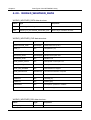
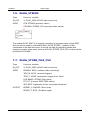
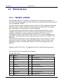
7.4. DLOG_DT
Type
Function module:
IN_OUT
X: DLOG_DATA (DLOG data structure)
INPUT
FMT: STRING (formatting parameters)
COLUMN: STRING (40) (process value name)
DELTA: UDINT (diference in seconds)
The module DLOG_DT is for logging (recording) of a date or time value of
type STRING, and can only be used in combination with a DLOG_STORE_*
module, as this coordinates the record the data by the data structure X.
Using FMT parameter, the formatting will be set. In the FMT parameter can
also be combined with normal text formatting parameters. See
documentation on the block DT_TO_STRF. If the FMT parameter is not
specifed, the default formatting
'#A-#D-#H #N:#R:#T' is used.
At recording formats that support a process value name, such as at
DLOG_STORE_FILE_CSV a name can be provided at COLUMN".
If with DELTA parameter a value greater than 0 is specified, the automatic data
logging is enabled via differential monitoring. If time changes by the value of DELTA
automatically a record is stored. This feature can be applied in parallel to the central
trigger on the DLOG_STORE_ * module. If, for example DELTA is the value 30,
automatically every 30 seconds a record is saved.
50
Version 1.21
Chapter 7.
Data Logger
Example:
FMT := '#A-#D-#H-#N:#R:#T'
resuls '2011-12-22-06:12:50'
7.5. DLOG_REAL
Type
Function module:
IN_OUT
X: DLOG_DATA (DLOG data structure)
INPUT
VALUE: REAL (process value)
N: INT (number of decimal places)
D : STRING(1) (decimal punctuation character)
COLUMN: STRING (40) (process value name)
DELTA: REAL (diference value)
The module DLOG_REAL is for logging (recording) of a process value of
type REAL, and can only be used in combination with a DLOG_STORE_*
module, as this coordinates of the data structure X to record the data.
Using parameter N defnes the number of desired decimal places. See
documentation on the module REAL_TO_STRF. The D input determines
which character represents the decimal point. Passed with no sign of
parameter D, automatically ',' is used.
At recording formats that support a process value name, such as at
DLOG_STORE_FILE_CSV a name can be provided at COLUMN". If with DELTA
parameter a value not equal 0.0 is specified, the automatic data logging is enabled
via differential monitoring. Changing the value of VALUE to + / - DELTA automatically
stores a record. This feature can be applied in parallel to the central trigger on the
DLOG_STORE_ * module.
51
Version 1.21
Chapter 7.
Data Logger
7.6. DLOG_STRING
Type
Function module:
IN_OUT
X: DLOG_DATA (DLOG data structure)
INPUT
STR: STRING (process value)
COLUMN: STRING (40) (process value name)
The module DLOG_DINT is for logging (recording) of a process value of type DINT,
and can only be used in combination with a DLOG_STORE_* module, as this
coordinates of the data structure X to record the data. At recording formats that
support a process value name, such as at DLOG_STORE_FILE_CSV a name can be
provided at COLUMN".
7.7. DLOG_STORE_FILE_CSV
Type
Function module:
IN_OUT
X: DLOG_DATA (DLOG data structure)
INPUT
ENABLE: BOOL (release data recording)
TRIG_M: BOOL (manual trigger)
TRIG_T: UDINT (automatic trigger over time)
FILE NAME: STRING (fle name)
DTI: DT (Current DATE-TIME value)
SEP: BYTE (separator of the recorded elements)
OUTPUT
ERROR_C: DWORD (Error code)
ERROR_T: BYTE (Problem type)
52
Version 1.21
Chapter 7.
Data Logger
The module DLOG_STORE_FILE_CSV is for logging (recording) of the
process values in a CSV formatted fle. The data can be passed with the
modules DLOG_DINT, DLOG_REAL, DLOG_STRING, DLOG_DT. The
parameter TRIG_M (positive pulse) is used to manually trigger (start) the
storage of process data. With Parameters TRIG_T an automatic timecontrolled release can be realized. If the current date / time value divided
by the parameterized TRIG_T value with residual value is 0, then a Save is
performed.
This also ensures that the store is always performed at the same time
Examples:
TRIG_T = 60
every 60 sec at each new minute in second 0 a store is performed.
TRIG_T = 10
In second 0,10,20,30,40,50 a store is performed.
TRIG_T = 3600
At after each new hour at minute 0 and second 0 a store is performed.
The triggers TRIG_T and TRIG_M can be used in parallel independent of
each other.
With parameters FILENAME the fle name (including path if necessary) is
defned. If the flename is changed during the recprding, it will
automatically on-the-fy changed to the new record fle (with no data loss).
This change can also be automated. The parameter FILE NAME supports
the use of date / time parameter (see documentation from the module
DT_TO_STRF)
Example: FILE NAME = 'Station_01_#R.csv'
At position of '#R' automatically the current minute number is entered. This means
that automatically every minute the file name changes, and therefore the data is
written into the file. Thus, within an entire hour 60 files are created and filled with
data, and in the ring buffer manner overwritten again and again.
53
Version 1.21
Chapter 7.
Data Logger
A recording can be done automatically and creates every day, week, month, etc. a
new file as desired. If a new FILE NAME is detected, a possibly existing file is erased
and rewritten.
On DTI parameters, the current date / time value has to be transferred. In SEP the
ASCII code of the delimiter is given.
CSV file format:
See:
http://de.wikipedia.org/wiki/CSV_(Dateiformat)
Example of a CSV delimited file ';' and column headings
Date / Time;Z1;Z2;seconds
2010-10-22-06:00:00;1;2;00
2010-10-22-06:00:06;1;2;06
2010-10-22-06:00:12;1;2;12
2010-10-22-06:00:18;1;2;18
ERROR_T:
Value
Properties
1
Problem: FILE_SERVER
The exact meaning of ERROR_C can be read at block FILE_SERVER
7.8. DLOG_STORE_RRD
Type
Function module:
IN_OUT
X: DLOG_DATA (DLOG data structure)
INPUT
ENABLE BOOL (Enable data recording)
TRIG_M: BOOL (manual trigger)
TRIG_T: UDINT (automatic trigger over time)
URL: STRING(string_length) (URL address of the server)
DTI: DT (Current DATE-TIME value)
SEP: BYTE (separator of the recorded elements)
54
Version 1.21
Chapter 7.
Data Logger
Dns_ip4: DWORD (IP address of the DNS server)
TIMEOUT: TIME (monitoring time)
OUTPUT
DONE: BOOL (Data transfer completed without error)
ERROR_C: DWORD (Error code)
ERROR_T: BYTE (Problem type)
The module DLOG_STORE_RRD serves for logging (recording) of the
process values in an RRD database. The data can be passed with the
modules DLOG_DINT, DLOG_REAL, DLOG_STRING, DLOG_DT. The
parameter TRIG_M (positive pulse) is used to manually trigger (start) the
storage of process data. With Parameters TRIG_T an automatic timecontrolled release can be realized. If the current date / time value divided
by the parameterized TRIG_T value with residual value is 0, then a Save is
performed.
This also ensures that the store is always performed at the same time
Examples:
TRIG_T = 60
every 60 sec at each new minute in second 0 a store is performed.
TRIG_T = 10
In second 0,10,20,30,40,50 a store is performed.
TRIG_T = 3600
At after each new hour at minute 0 and second 0 a store is performed.
The triggers TRIG_T and TRIG_M can be used in parallel independent of
each other.
On DTI parameters, the current date / time value has to be transferred. In SEP the
ASCII code of the delimiter is given.
If an error occurs during the query it is reported in ERROR_C in
combination with ERROR_T.
ERROR_T:
55
Version 1.21
Chapter 7.
Data Logger
Value
Properties
1
The exact meaning of ERROR_C can be read at module DNS_CLIENT
2
The exact meaning of ERROR_C can be read at module HTTP_GET
3
ERROR_C = 1: Data from the RRD-Server (PHP script) are not adopted.
4
ERROR_C = 1: The data could be passed in the URL string .
Number of parameters or reduce the amount of data (URL + data <= 250 characters)
With the parameter URL, the access path and the php-script-call is passed.
An example URL:
http://my_servername/myhouse/rrd/test_rrd.php?rrd_db=test.rrd&value=
DNS server or IP address
Access path and name of the php-script
php-script parameter 1 = Database Name
php-script parameter 2 = Process values
The module automatically copies all process values behind "&value="
so that then the following data (example) used
http://my_servername/myhouse/rrd/test_rrd.php?
rrd_db=test.rrd&value=10:20:30:40:50:60:70
The individual process data are, using the parameter SEP (separator), separated
from each other.
It is important that the passed URL string and the process data are not longer than
250 characters.
The structure of the URL is only an example, and can in principle be designed with
own free server applications and scripts in conjunction with their.
What are the possibilities for and benefits rrdtool
rrdtool is a program that saves the time-related measurement data, and
summarizes and visualizes the data. The program was originally
developed by Tobias Oetiker and under the GNU General Public License
(GPL). By publishing a free software now many other authors new
functionality and bug fxes have contributed. rrdtool is available as source
code and an executable program for many operating systems.
Source: http://de.wikipedia.org/wiki/RRDtool
56
Version 1.21
Chapter 7.
57
Data Logger
Version 1.21
Chapter 7.
Data Logger
Sample graphs:
Source - http://www.mrtg.org/
58
Version 1.21
Chapter 7.
Data Logger
What is required: hardware, software, tools, etc.
PLC with Network OSCAT-lib
A power-saving PC for the duration of operation (24/7).
On the PC, rrdtol and the php scripts are installed.
The scripts have been developed on a Linux-Xubuntu-PC with PHP.
Quick Start:
59
•
A sample program with some values may be recorded, is found the
OSCAT network.lib under demo/DLOG_RRD_DEMO.
•
The rrdtool installation on Xubuntu (DEBIAN) PC is processed either with
the Synaptic package manager and select install rrdtool, or in the console
with "apt-get install rrdtool".
•
Script: create_test_rrd_db.php = Creates a new rrd database, and once must
be adapted if necessary.
•
Script: test_rrd.php = This script is called by the PLC with the OSCAT
function module via HTTP-GET. Must usually are not adjusted, and
outputs an error code. If error-free, then output is a "0".
•
Script: chart_test.php = Script to create the charts from the rrd-DB and
display it on a website. Must usually are not adjusted, and outputs an
error code. If error-free is then output a "0".
•
Download the three php scripts in the folder to a PC, ie./ var / www / rrd /
and do not forget to adjust the appropriate access rights.
Version 1.21
Chapter 7.
Data Logger
The demo program in conjunction with the demo php scripts create the
following data or graphic.
Links
http://www.mrtg.org/rrdtool/
http://de.wikipedia.org/wiki/RRDtool
http://www.rrze.uni-erlangen.de/dienste/arbeitenrechnen/linux/howtos/rrdtool.shtml
http://arbeitsplatzvernichtung-durch-outsourcing.de/marty44/rrdtool.html
60
Version 1.21
Chapter 7.
Data Logger
php-script - Examples / Templates
create_test_rrddb.php
#!/etc/php5/cli -q
<?php
error_reporting(E_ALL);
# ==================================
# Creates a rrd database
# Is called once from the console
# 12/11/2010 by NetFritz
# ==================================
# Create wp.rrd creates the database test.rrd
# - Step 60 all 60 sec, a value is expected
# DS:t1:GAUGE:120:0:100 a data source named t1 is created
#
the type is gauge. It is waiting 120sec for new data, if not,
#
the data is written into the database as UNKNOWN.
#
the minimum and maximum reading
# RRA:AVERAGE:0.5:1:2160 this is the rrd-Archiv
rage interval deviation
AVERAGE=average 0.5= ave-
#
36h archive every minute, a value, 1:2160=1h =36h 3600sec*3600=129 600
1Minute =60seconds every minute a value, 129600/60 = 2160 Entries
# RRA:AVERAGE:0.5:5:2016 1week archive all 5minutes 1value, 3600*24*7 days
= 604800Sec / (5 minutes +60 sec = 2016 entries
# RRA: AVERAGE: 1Values 0.5:15:2880 30Days archive all 15minutes,
# RRA: AVERAGE: 1 year 0.5:60:8760 archive all 60Minuten a value
# It is now starting
$ Command = "rrdtool create test.rrd \
- Step 60 \
DS:t1:GAUGE:120:0:100 \
DS:t2:GAUGE:120:0:100 \
DS:t3:GAUGE:120:0:100 \
DS:t4:GAUGE:120:0:100 \
DS:t5:GAUGE:120:0:100 \
DS:t6:GAUGE:120:0:100 \
DS:t7:GAUGE:120:0:100 \
RRA:AVERAGE:0.5:1:2160 \
RRA:AVERAGE:0.5:5:2016 \
RRA:AVERAGE:0.5:15:2880 \
RRA:AVERAGE:0.5:60:8760";
61
Version 1.21
Chapter 7.
Data Logger
system($command);
?>
test_rrd.php
<?php
# Called by control with
# Http://mein_server/test_rrd.php?rrd_db=test.rrd&value=10:20:30:40:50:60
$ Rrd_db = urldecode($ _GET['rrd_db']);
$ Value = urldecode($ _GET['value']);
# Name of the RRD database
# Submitted values
# $ array_values = explode(":",$value);
# echo "$rrd_db <br>";
# print_r($array_value);
# echo "<br>";
$commando = "/usr/bin/rrdtool update " . $rrd_db . " N:" . $value;
system($commando,$fehler);
echo $fehler . $commando;
?>
chart_test_rrd.php
<?php
/ / Create chart for test scores, and is invoked by the browser
$command="/usr/bin/rrdtool graph test0.png \
--vertical-label=Test \
--start end-12h \
--width 600 \
--height 200 \
--alt-autoscale \
DEF:t1=test.rrd:t1:AVERAGE \
DEF:t2=test.rrd:t2:AVERAGE \
DEF:t3=test.rrd:t3:AVERAGE \
DEF:t4=test.rrd:t4:AVERAGE \
DEF:t5=test.rrd:t5:AVERAGE \
DEF:t6=test.rrd:t6:AVERAGE \
DEF:t7=test.rrd:t7:AVERAGE \
LINE1:t1#FF0000:Test1 \
LINE1:t2#6EFF00:Test2 \
LINE1:t3#CD04DB:Test3 \
62
Version 1.21
Chapter 7.
Data Logger
LINE1:t4#008000:Test4 \
LINE1:t5#0000FF:Test5 \
LINE1:t6#0000FF:Test6 \
LINE1:t7#0000FF:Test7 \
COMMENT: 'The last 12 hours' ";
system($command);
echo "<!DOCTYPE HTML PUBLIC \"-//W3C//DTD XHTML 1.0 Transitional//EN\"
\"http://www.w3.org/TR/xhtml1/DTD/xhtml1-transitional.dtd\">\n";
echo "<html xmlns=\"http://www.w3.org/1999/xhtml\">\n";
echo "
echo "
<head>\n";
<title>Test</title>\n";
echo "
</head>\n";
echo "
<body>\n";
echo ("<center><img src='test0.png'></center>\n");
echo "
<center>Die letzten 12h</center>\n";
# Echo "Error =". $fehler;
echo "
</body>\n";
echo "</html>\n";
?>
7.9. DLOG_FILE_TO_FTP
Type
Function module:
IN_OUT
X: DLOG_DATA (DLOG data structure)
INPUT
FTP_URL: STRING(STRING_LENGTH) (FTP access path)
FTP_ACTIV : BOOL (PASSIV = 0 / ACTIV = 1)
FILE_DELETE: BOOL (delete fles after transfer)
TIMEOUT: TIME (time)
RETRY: INT (number of repetitions)
RETRY_TIME: TIME (waiting period before repetition)
Dns_ip4: DWORD (IP4 address of the DNS server)
63
Version 1.21
Chapter 7.
Data Logger
Dns_ip4: DWORD (IP4 address of the DNS server)
OUTPUT
DONE: BOOL (Transfer completed without error)
BUSY: BOOL (Transfer active)
ERROR_C: DWORD (Error code)
ERROR_T: BYTE (Problem type)
The module DLOG_FILE_TO_FTP is used to automatically transfer the by
DLOG_STORE_FILE_CSV generated from fles to an FTP-server. The FTP_URL
parameter contains the name of the FTP server and optionally the user
name and password, an access path and an additional port number for the
data channel. If no Username or password is transferred, the device
automatically tries to register as "Anonymous". The parameter FTP_ACTIV
determined whether the FTP server is operated in active or passive mode.
In the ACTIV mode, the FTP server tries to establish the data channel for
control, however these may cause problems by security software, frewall,
etc. because it could block the connection request. For this purpose, in the
frewall a corresponding exception rule has to be defned. In the passive
mode, this problem is alleviated since the controller establishes the
connection, and can easily pass through the frewall. The control channel is
always set up on port 20, and the data channel via standard PORT21, but
this is in turn is depending whether active or passive mode is used, or
optional PORT number in the FTP-URL is specifed. With the parameter
FILE_DELETE can be determined whether the source fle should be deleted
after successful transfer. This works on FTP and even on the control side.
In specifying FTP directories the behavior depends on FTP server, whether
they exist in this case or are created automatically. Normally, these should
be already available. The size of fles is no limit per se, but there are
practical limits: Space on PLC, FTP storage and the transmission time. With
dns_ip4 the IP address of the DNS server must be specifed, if in the FTP
URL a DNS name is given, alternatively, an IP address can be entered in
the FTP URL. At parameters PLC_IP4 the own IP addresses has to be
supplied. If errors occur during transmission these are passed to the
output ERROR_C and ERROR_T. As long as the transfer is running, BUSY =
64
Version 1.21
Chapter 7.
Data Logger
TRUE, and after an error-free completion of the operation, DONE = TRUE.
Once a new transfer is started, DONE, ERROR_T and ERROR_C are reseted.
If parameter RETRY = 0, then the FTP transfer was repeated until it
completes successfully. If RETRY state at a value > 0, the FTP transfer is
just as often repeated in transmission failure. Then this job is simply
discarded and the process continues with the next fle. With RETRY-TIME
the waiting time between the repetitions can be defned.
The module has integrated the IP_CONTROL and must not be externally
linked to this, as it by default would be necessary.
Background: http://de.wikipedia.org/wiki/File_Transfer_Protocol
URL examples:
ftp://username:password@servername:portnummer/directory/
ftp://username:password@servername
ftp://username:password @ servername / directory /
ftp://servername
ftp://username:[email protected]/directory/
ftp://192.168.1.1
65
Version 1.21
Chapter 7.
Data Logger
ERROR_T:
Value
Properties
1
Problem: DNS_CLIENT
The exact meaning of ERROR_C can be read at module DNS_CLIENT
2
Problem: FTP control channel
The exact meaning of ERROR_C can be read at module IP_CONTROL
3
Problem: FTP data channel
The exact meaning of ERROR_C can be read at module IP_CONTROL
4
Problem: FILE_SERVER
The exact meaning of ERROR_C can be read at block FILE_SERVER
5
Problem: END - TIMEOUT
ERROR_C contains the left WORD of the step number, and the right WORD has the response code received by the FTP server.
The parameters must be considered first as a HEX value, divided into two WORDS, and
then be considered as a decimal value.
Example:
ERROR_T = 5
ERROR_C = 0x0028_00DC
End-step number 0x0028 = 40
Response-Code 0x00DC = 220
7.10. DLOG_FILE_TO_SMTP
Type
Function module:
IN_OUT
SERVER: STRING (URL of the SMTP server)
MAIL FROM: STRING (return address)
MAILTO: STRING (string_length) (recipient address)
SUBJECT: STRING (subject text)
SUBJECT: STRING (subject text)
FILES: STRING (string_length) (fles to be sent)
X: DLOG_DATA (DLOG data structure)
66
Version 1.21
Chapter 7.
INPUT
Data Logger
FILE_DELETE: BOOL (delete fles after transfer)
TIMEOUT: TIME (time)
DTI: DT (current date-time)
DTI_OFFSET: INT (time zone ofset from UTC)
RETRY: INT (number of repetitions)
RETRY_TIME: TIME (waiting period before repetition)
Dns_ip4: DWORD (IP4 address of the DNS server)
OUTPUT
DONE: BOOL (Transfer completed without error)
BUSY: BOOL (Transfer active)
ERROR_C: DWORD (Error code)
ERROR_T: BYTE (Problem type)
The module DLOG_FILE_TO_SMTP is used to automatically transfer the of
DLOG_STORE_FILE_CSV generated fles as e-mail to an e-mail server.
The module uses internally the SMTP_CLIENT for sending.
The SERVER parameter contains the name of the SMTP server and
optionally the user name and password and a port number. If you pass a
user name and password, the procedure is according to standard SMTP.
SERVER: URL Examples:
username:password@smtp_server
username:password@smtp_server:portnumber
smtp_server
Special case:
67
Version 1.21
Chapter 7.
Data Logger
If in the username is a '@' included this must be passed as '%' - character,
and is then automatically corrected by the module again.
By specifying user and password the Extend-SMTP is used, and
automatically the safest possible Authentication method is used. If
parameter is to specify the MAIL FROM sender address:
i.e. [email protected]
Optionally, an additional "Display Name" be added This is displayed the
email client automatically instead of the real return address. Therefore,
always an easily recognizable name to be used.
i.e.. [email protected];Station_01
The email client shows as the sender then "Station_01". Thus, more
people will use the same email address but send a own "Alias".
At the MAILTO parameter can To, Cc, Bc be specifed. The diferent groups
of recipients are specifed by '#' as the separator in a list. Multiple
addresses within the same group are divided with the separator ";" . In
each group can be defned unlimited count of recipients, the only
limitation is the length of the mailto string.
To;To..#Cc;Cc...#Bc;Bc...
Examples.
[email protected];[email protected]#[email protected]#[email protected]
defnes two TO-addresses, one CC-address and a Bc-address
##[email protected]
defnes only one BC-address.
With subject, a subject text will be specifed, as well as with BODY an email
text content. The current Date / Time value must be defnded at DTI, and
at DTI_OFFSET the correction value as an ofset in minutes from UTC
(Universal Time). If the DTI in UTC time is passed, at DTI_OFFSET a 0 must
be passed.
The monitoring time can be specifed with parameter TIMEOUT. At dns_ip4
must be specifed the IP address of the DNS server, if in SERVER a DNS
name is specifed. If errors occur during the transmission, they are passed
at ERROR_C and ERROR_T. As long as the transfer is running, BUSY =
TRUE, and after an error-free completion of the operation, DONE = TRUE.
Once a new transfer is started, DONE, ERROR_T and ERROR_C are reseted.
If parameter RETRY = 0, then the SMTP transfer was repeated until it
completes successfully. If RETRY state at a value > 0, then the SMTP
68
Version 1.21
Chapter 7.
Data Logger
transfer is just as often repeated at transmission failure. Then this job is
simply discarded and the process continues with the next fle. With RETRYTIME the waiting time between the repetitions can be defned.
The parameter FILE_DELETE = TRUE a fle is deleted on the controller after
successful transfer via email.
The module has integrated the IP_CONTROL and so must not be externally
linked to this, as it would be at default necessary.
Basics:
http://de.wikipedia.org/wiki/SMTP-Auth
http://de.wikipedia.org/wiki/Simple_Mail_Transfer_Protocol
ERROR_T:
Value
Properties
1
Problem: DNS_CLIENT
The exact meaning of ERROR_C can be read at module DNS_CLIENT
2
Problem: SMTP Channel
The exact meaning of ERROR_C can be read at module IP_CONTROL
4
Problem: FILE_SERVER
The exact meaning of ERROR_C can be read at block FILE_SERVER
5
Problem: END - TIMEOUT
ERROR_C contains the left WORD the end of the step number, and in the right WORD
the last response code received by the SMTP server.
The parameters must be considered first as a HEX value, divided into two WORDS, and
then be considered as a decimal value.
Example:
ERROR_T = 5
ERROR_C = 0x0028_00FA
End-step number 0x0028 = 40
Response-Code 0x00DC = 250
7.11. UNI_CIRCULAR_BUFFER
69
Type
Function module:
IN_OUT
DATA: UNI_CIRCULAR_BUFFER_DATA (data storage)
Version 1.21
Chapter 7.
Data Logger
The module UNI_CIRCULAR_BUFFER is a ring buffer in the FIFO (first in - first out)
principle, and can process any data as a byte stream.
For this purpose, in the data structure UNI_CIRCULAR_BUFFER_DATA all can be
processed.
The following commands are supported on DATA.D_MODE.
01
Element to write to bufer
10
Element of Bufer read but not to remove
11
The above command 10 read with item is removed.
12
read element from bufer and remove
99
Bufer is reset. All data is deleted
With DATA.D_HEAD (WORD) in the right byte can be provided the element
type, and in the left byte optional an additional user ID.
D_HEAD =
LEFT-BYTE (ADD-Ino), RIGHT-BYTE (Type ID)
Type codes:
1 = STRING (For DATA.D_STRING, the string must be provided)
2 = REAL
(For DATA.D_REAL, the REAL value is passed)
3 = DWORD ( In the DWORD the DATA.D_DWORD must be passed)
X = header information without data
In DATA.BUF_SIZE the number of bytes output, to show the dropped items in total.
With DATA.BUF_COUNT the number of in Buffer contained elements is provided.
And on BUF_USED will issue the occupancy of the buffer as a percentage value.
When an item is written in the buffer, and the required free space (memory) does not
exist, after calling the module, the DATA.D_MODE remains unchanged. The
command was successfu only if D_MODE contains 0 after module call.
When reading elements, the same operation is essential.
70
Version 1.21
Chapter 7.
Data Logger
Only if D_MODE subsequently is 0, in D_HEAD the data type can be found, and if
necessary, the data from D_STRING, D_REAL, D_DWORD can be read. After
successful reading step, the deletion of the element to be performed with command
11.
Example: Writing element:
DATA.D_MODE: = 1; (* command to write data *)
DATA.D_HEAD: = 1; (* element-type = STRING *)
DATA.D_STRING:= 'This is the text';
module-call()
if DATA.D_MODE = 0, then the element was successfully saved
Example: Reading element:
DATA.D_MODE:= 10; (* read command * element)
module-call()
result
DATA.D_HEAD = 1; (* Element-Type = STRING *)
DATA.D_STRING = 'This is the text';
DATA.D_MODE = 0
Example: Delete element:
DATA.D_MODE:= 11; (* command * delete item)
module-call()
DATA.D_MODE = 0; (* item was deleted *)
71
Version 1.21
Chapter 8.
Converter
8. Converter
8.1. BASE64
The BASE64 encoding is a process for Encoding of 8-bit binary data into a
string consisting of only 64 globally available ASCII characters. Application is HTTP Basic Authentication, PGP signatures and keys, and MIME encoding for e-mail. To enable the SMTP protocol as the easy transport of binary data, a conversion is necessary, as foreseen in the original version, only
7-bit ASCII characters.
When encoding always three bytes of byte stream (24 bit) are devided in
6-bit blocks. Each of these 6-bit blocks results in a number between 0 and
63. This results in the following 64 printable ASCII characters [A-Z] [a-z]
[0-9], [+/]. The encoding increases the space requirements of the data
stream by 33%, from 3 characters each to 4 characters each. If the length
of the coding is not divisible by 4, fller characters will be appended at the
end. In this case the sign "=" is used .
8.2. BASE64_DECODE_STR
Type
Function module
Input
RUN: BOOL (positive edge starts conversion)
Output
DONE: BOOL (TRUE if conversion is completed)
I/O
STR1: STRING(192) (text in BASE64 format)
STR2: STRING(144) (converted normal text)
72
Version 1.21
Chapter 8.
Converter
With a BASE64_DECODE_STR encoded in BASE64 text can be converted
back to plain text. With a positive edge of RUN the process starts. Here
DONE is immediately reseted, if it has been set by a previous conversion.
The BASE64 encoded text is passed on STR1, and after the conversion the
plain text is available in STR2, and DONE is set to TRUE.
Example:
Text in STR1
'T3BlbiBTb3VyY2UgQ29tbXVuaXR5IGZvciBBdXRvbWF0aW9uIFRlY2hub2xv Z3k='
Result in STR2
Text in STR2 = 'Open Source Community for Automation Technology'
8.3. BASE64_DECODE_STREAM
Type
Function module
Input
SIZE1: INT (number of bytes in the BUF1 for decode)
Output
SIZE2: INT (number of bytes in BUF2 of the decoded results)
I/O
BUF1: ARRAY [0..63] OF BYTES (BASE64 data for conversion)
BUF2: ARRAY [0..47] OF BYTES (converted data)
With BASE64_DECODE_STREAM arbitrarily long BASE64 byte streams are
decoded. In one pass, up to 64 bytes are decoded, which in turn emerged
from a maximum of 48 bytes each. Here, the source data is passed to the
73
Version 1.21
Chapter 8.
Converter
decoder over BUF1 in the data-stream manner as individual blocks of
data, and in decoded form re-issued in BUF2. The user has to provide the
further processing of the BUF2 data before the next block of data is converted. The number of bytes in BUF2 is issued by SIZE2 from the module.
8.4. BASE64_ENCODE_STR
Type
Function module
Input
RUN: BOOL (positive edge starts conversion)
Output
DONE: BOOL (TRUE if conversion is completed)
I/O
STR1: STRING (144) (Text to convert)
STR2: STRING (192) (converted text in BASE64 format)
With BASE64_ENCODE_STR a standard text can be converted to a BASE64
encoded text. With a positive edge of RUN the process starts. Here DONE
is immediately reseted, if it has been set by a previous conversion. The
BASE64 encoded text is passed on STR1, and after the conversion the BASE64 text is available in STR2, and DONE is set to TRUE.
Example:
Text in STR1 = 'Open Source Community for Automation Technology'
Result in STR2
'T3BlbiBTb3VyY2UgQ29tbXVuaXR5IGZvciBBdXRvbWF0aW9uIFRlY2hub2xv Z3k='
8.5. BASE64_ENCODE_STREAM
74
Type
Function module
Input
SIZE1: INT (number of bytes in the BUF1 to encode)
Version 1.21
Chapter 8.
Converter
Output
SIZE2: INT (number of bytes in the encoded BUF2 results)
I/O
BUF1: ARRAY [0..47] OF BYTES (data to convert)
BUF2: ARRAY [0..63] OF BYTES (BASE64 converted data)
With BASE64_ENCODE_STREAM arbitrarily long byte data stream according to BASE64 can be encoded. In one pass, up to 48 bytes are conver ted, in turn, result more than 64 bytes. Here, the source data is passed to
the encoder over BUF1 in the data-stream manner as individual blocks of
data, and in coded form re-issued in BUF2. The user has to provide the further processing of the BUF2 data before the next block of data is converted. The number of bytes in BUF2 is issued by SIZE2 from the module.
8.6. HTML_DECODE
Type
Function : STRING(string_length)
Input
IN: STRING( String )
Output
STRING(string_length) (string)
HTML_DECODE converts reserved characters which are in the form
&name; stored HTML code, in the original character. In addition, all coded
characters are converted into the corresponding ASCII code. Special characters can be represented by the following string in HTML:
- &#NN, where NN represents the position of the character within the character map in decimal notation.
- &#xNN, or &#XNN where NN represents the position of the character within the character table in hexadecimal notation.
&name; Special characters have names like € for €.
The reserved characters in HTML are:
& Is encoded as &
75
Version 1.21
Chapter 8.
Converter
> Is encoded as >
< Is encoded as <
" is coded as "
Examples:
HTML_DECODE('1 ist >als 0') = '1 is > als 0';
HTML_DECODE('&#D79;&#D83;&#D67;&#D65;&#D84;') = 'OSCAT';
HTML_DECODE('&#xH4F;&#xH53;&#xH43;&#xH41;&#xH54;') = 'OSCAT';
HTML_DECODE('&#XH4F;&#XH53;&#XH43;&#XH41;&#XH54;')
'OSCAT';
=
8.7. HTML_ENCODE
Type
F unction : STRING(string_length)
Input
IN: STRING( String )
M: BOOL (mode)
Output
STRING(string_length) (string)
Html_encode converts in HTML reserved characters to form &Name;. If the
input M is set to TRUE also all the characters with the code 160-255 and
128 are implemented in the &Name convention.
Caution should be exercised in the use of character sets because they are
not the same on all systems and deviations are common in special characters. Thus, for example, not all systems the € character at position 128 in
the character map.
The reserved characters in HTML are:
& Is encoded as &
> Is encoded as >
< Is encoded as <
" is coded as "
Html_encode converts the string '1 > than 0 'into '1 is > than 0'.
76
Version 1.21
Chapter 8.
Converter
8.8. IP4_CHECK
Type
Function : BOOL
Input
NIP: DWORD (network IP address)
LIP: DWORD (Local IP address)
SM: DWORD ( Subnet Mask)
Output
BOOL (TRUE if NIP and LIP are in the same Subnet )
IP4_CHECK checks if a network address of the NIP and the local address
LIP are in the same Subnet lie. Both addresses will be frst masked with
the Subnet mask and then tested for equality. Only the bits which are in
the Subnet Mask TRUE are examined for equality. The network addresses
must correspond to the IPv4 format and presented as a DWORD. If IP addresses must be tested that are String they are to be converted to
DWORD before.
The following example shows 2 IP addresses and a Subnet Mask as String
are tested after appropriate conversion to DWORD there. The output is
TRUE because both addresses are in the same Subnet .
8.9. IP4_DECODE
Type
77
Function : DWORD
Input
STR: STRING(15) (string that contains the IP address)
Output
DWORD (decoded IP v4 address)
Version 1.21
Chapter 8.
Converter
IP4_DECODE decodes the in STR stored string as a IP v4 address and returns it as a DWORD. A return of 0 means an invalid address or an address
of '0.0.0.0 ' was evaluated. IP4 may be used for evaluating a Subnet Mask
of the IP v4 format.
8.10. IP4_TO_STRING
Type
Function : STRING(15)
Input
IP4: BOOL (string that contains the IP address)
Output
DWORD (decoded IP v4 address)
IP4_TO_STRING converts the IP4 address stored as DWORD in a string. The
format is 'NNN.NNN.NNN.NNN'.
8.11. IS_IP4
Type
Function : BOOL
Input
STR: STRING (string to be tested)
Output
BOOL (TRUE if STR contains a valid IP v4 address)
IS_IP4 checks if the string str contains a valid IP v4 address, if not FALSE is
returned. A valid IP v4 address consists of 4 numbers from 0 - 255 and
they are separated each with one point. The address 0.0.0.0 is there classifed as wrong.
IS_IP4(0.0.0.0) = FALSE
IS_IP4(255.255.255.255) = TRUE
IS_IP4(256.255.255.255) = FALSE
IS_IP4(0.1.2.) = FALSE
IS_IP4(0.1.2.3.) = FALSE
78
Version 1.21
Chapter 8.
Converter
8.12. IS_URLCHR
Type
Function : BOOL
Input
IN: STRING (string to be tested)
Output
BOOL (TRUE if STR contains a valid IP v4 address)
IS_URLCHR checks if the string contains only valid characters for a URL encoding. If the string contains reserved characters it returns FALSE, otherwise TRUE.
For a URL following characters are valid:
[A..Z]
[a..z]
[0..9]
[-._~]
all other characters are reserved or not allowed.
8.13. MD5_AUX
Type
Function: DWORD
Input
N: INT (internal use)
A: DWORD (Internal use)
B: DWORD (Internal use)
C: DWORD (internal use)
D: DWORD (internal use)
X: DWORD (Internal use)
U: INT (internal use)
T: DWORD (Internal use)
At the MD5 hash generation several cycles through the complex mathematical calculations which are processed. Thus, the amount of redundant
code in the module MD5_STREAM remains small, periodic calculations
have been displaced as a macro in the MD5_AUX. This module has only in
conjunction with the block MD5_STREAM a useful application.
79
Version 1.21
Chapter 8.
Converter
8.14. MD5_STR
Type
Function module
Input
RUN: BOOL (Positive edge starts the calculation)
Output
DONE: BOOL (TRUE if calculations are complete)
MD5: ARRAY[0..15] OF BYTE (current MD5 hash)
I/O
STR: STRING(string_length) (Text for HASH creation)
With MD5_STR a string of the MD5 hash can be calculated by. In the STR a
string is passed to the module, and a positive edge at input "RUN", the
calculation starts. DONE is immediately reset at startup, and after the process is DONE is set to TRUE. Then, at the parameter HASH the actual calculated HASH value is available. (See module MD5-STREAM).
Example:
the MD5 hash of 'OSCAT' is 30f33ddb9f17df7219e1acdea3386743
8.15. MD5_STREAM
80
Type
Function module
I/O
MODE: INT(mode: 1 = init / 2 = Data Block / 3 = Complete)
Version 1.21
Chapter 8.
Converter
BUF: ARRAY[0..63] OF BYTES (source data)
MD5: ARRAY [0..15] OF BYTE (current MD5-HASH)
SIZE: UDINT (number of data)
Output
POS: UDINT(start address of the requested data block)
The module MD5_STREAM allows the calculation of the MD5 ( Message-Digest Algorithm 5 ) of a cryptographic hash function.
This can be created from any data stream a unique check value. It is virtually impossible to fnd two diferent messages with the same test value,
this is referred to as collisions free. This can be used to check a confguration fle for change or manipulation.
With the hash algorithm (MD5) a hash value is generated from 128 bits in
length for any data. The maximum length of the stream is on this module
is limited to 2^32 (4 gigabyte). The result is a 16 bytes hash value at parameters MD5.
Example:
There are 2000 bytes in a bufer and are read using the fle system in
blocks.
User set MODE to 1 and SIZE to 2000. Calling the MD5_STREAM
MD5 STREAM performs a initialization and set MODE to 2 and passes at
POS the index (base 0) of the desired data. At SIZE the number of data is
set, which are copied into the data memory BUF.
User copies the requested data in the BUF and calls the module
MD5_STREAM repeatedly. This step is repeated until MODE remains at 2.
If the MD5_STREAM has processed the last data block, this set MODE to 3.
It can also happen that the last block, that at the SIZE length zero is set,
therefore, so no data are copied into BUF .
81
Version 1.21
Chapter 8.
Converter
The current hash value can then be processed as a result.
Example:
the MD5 hash of 'OSCAT' is 30f33ddb9f17df7219e1acdea3386743
8.16. MD5_TO_STRH
Type
Function: STRING(32)
Input
MD5 : ARRAY[0..15] OF BYTE (MD5-HASH)
The module MD5 MD5_TO_STRH converts the MD5 byte array to a hex
string.
8.17. RC4_CRYPT_STREAM
Type
Function module
I/O
MODE: INT(mode: 1 = init / 2 = Data Block / 3 = Complete)
KEY: STRING(40) (320-bit long secret key)
BUF: ARRAY[0..63] OF BYTES (data block to process)
SIZE: UDINT (number of data)
Output
POS: UDINT(start address of the requested data block)
The module RC4_CRYPT_STREAM uses the RC4 data encryption to process
an almost arbitrarily long data stream. This standard is used for example
in an SSH, HTTPS, and WEP or WPA, and is thus widely used. The algorithm
can in principle operate at up to 2048 bit key, but this is limited to the mo82
Version 1.21
Chapter 8.
Converter
dule on a 40-character key (but it can always be adjusted to up to 250
characters). Thus, it presents a key length of 320 bits, which are designed
for applications on a PLC more than adequate. The maximum length of the
stream is on this module is limited to 2^32 (4 gigabyte). The module can
be used for encryption as well as to decrypt RC4 data. 64 bytes per cycle
can still be processed, they will be processed in serial block mode. The
data been encrypted or decrypted, remains in the module BUF for further
processing, and must, of course, processed previously by the user before
each new block of data.
Example:
There are 2000 bytes in a bufer and are read using the fle system in
blocks.
User sets mode is to 1 and SIZE to 2000. Calling the RC4_CRYPT_STREAM
RC4_CRYPT_STREAM performs initialization and set MODE to 2 and passes
at the POS the index (base 0) to the desired data. At SIZE the number of
data, to be copied into the data memory BUF, is set .
User copies the requested data in the BUF and calls the module
RC4_CRYPT_STREAM repeatedly. This step is repeated until MODE remains
at 2. If the RC4_CRYPT_STREAM has processed the last data block, this set
MODE to 3.
8.18. SHA1_STR
83
Type
Function module
Input
RUN: BOOL (Positive edge starts the calculation)
Version 1.21
Chapter 8.
Output
Converter
DONE: BOOL (TRUE if calculations are complete)
HASH : ARRAY[0..19] OF BYTE (actual SHA1-HASH)
I/O
STR: STRING(string_length) (Text for HASH creation)
With SHA1_STR the SHA1 hash can be calculated in a string. In the STR a
string is passed to the module, and a positive edge at input "RUN", the
calculation starts. DONE is immediately reset at startup, and after the process is DONE is set to TRUE. Then, at the parameter HASH the actual calculated HASH value is available. (See module SHA1-STREAM).
Example:
Hash value of 'OSCAT' is 4fe4fa862f2e7b91bf95abe9f22831247a3afd35
8.19. SHA1_STREAM
Type
Function module
I/O
MODE: INT(mode: 1 = init / 2 = Data Block / 3 = Complete)
BUF: ARRAY[0..63] OF BYTES (source data)
SHA1: ARRAY [0..19] OF BYTE (current SHA1-HASH)
SIZE: UDINT (number of data)
Output
POS: UDINT(start address of the requested data block)
The module SHA1_STREAM allows the calculation of standard cryptographic hash function SHA-1 (Secure Hash Algorithm).
84
Version 1.21
Chapter 8.
Converter
This can be created from any data stream a unique check value. It is virtually impossible to fnd two diferent messages with the same test value,
this is referred to as collisions free. This can be used to check a confguration fle for change or manipulation.
With the secure hash algorithm (SHA1) a hash value is generated from
160 bits in length for any data. The maximum length of the stream is on
this module is limited to 2^32 (4 gigabyte). The result is a 20-byte hash
value, issued as ARRAY [0..19] OF BYTE.
Example:
There are 2000 bytes in a bufer and are read using the fle system in
blocks.
User sets MODE to 1 and SIZE to 2000. Calling the SHA1_STREAM
SHA1_STREAM performs initialization and set MODE to 2 and passes at the
POS the index (base 0) of the desired data. At SIZE the number of data, to
be copied into the data memory BUF, is set .
User copies the requested data in the BUF and calls the module
SHA1_STREAM repeatedly. This step is repeated until MODE remains at 2.
[fzy] If the SHA1_STREAM has processed the last data block, this set MODE
to 3. It can also happen that the last block, that at the SIZE length zero is
set, therefore, so no data are copied into BUF .
The current hash value can then be processed as a result.
Example:
Hash value of 'OSCAT' is 4fe4fa862f2e7b91bf95abe9f22831247a3afd35
8.20. SHA1_TO_STRH
Type
85
Function: STRING (40)
Version 1.21
Chapter 8.
Input
Converter
MD5 : ARRAY[0..19] OF BYTE (SHA1 hash)
The module converts the SHA1_TO_STRH SHA1 byte array to a hex string.
8.21. STRING_TO_URL
Type
Input
Function : URL
STR: STRING (string_length) ( Unifed Resource Locator )
DEFAULT_PROTOCOL: STRING(replacement protocol)
DEFAULT_PATH: STRING (alternate path)
Output
URL (URL)
STRING_TO_URL split a URL ( Uniform Resource Locator ) into its components and stores it in the data type URL. If in STR no path or protocoll is
specifed, so the function sets the missing values automatically with the
specifed replacement values.
A URL is as follows:
Protocol : / / user : Password @ domain : port / path ? query # anchor
Example: ftp://hugo:[email protected]:1234/download/manual.html
some parts of the URL are optional, such as user name, password, Anchor,
Query ...
86
Version 1.21
Chapter 8.
Converter
8.22. URL_DECODE
Type
Fu FUNCTIONS: STRING(string_length)
Input
IN: STRING ( String )
Output
STRING(string_length) (string)
URL_DECODE converts the in %HH encoded special characters in the
string IN in the appropriate ASCII code. In a URL encoding only the characters [A.. Z, a.. Z found, 0 .9, -._~] can occur. Other characters with a %
character, followed by 2 characters long Hexadecimal of the character are
shown. The reserved character '#' is encoded as a '%23'.
8.23. URL_ENCODE
Type
Function : STRING(STRING_LENGTH)
Input
IN: STRING ( String )
Output
STRING (STRING_LENGTH) (string)
URL_ENCODE converts reserved characters in the string IN in the string
'%HH'. In a URL encoding only the characters [A.. Z, a.. Z found, 0 .9, -._~]
can occur. Other characters with a % sign followed by the two-character
hexadecimal code of the character are shown. The reserved character '#'
is encoded as a '%23'.
8.24. URL_TO_STRING
87
Type
Function: STRING (string_length)
Input
IN: STRING( Unifed Resource Locator )
Output
URL (URL)
Version 1.21
Chapter 8.
Converter
URL_TO_STRING generates from stored data in IN with type URL a Unifed
Resource Locator as String .
A URL is as follows:
protokoll://user:passwort@domain:port/path?query#anchor
Example: ftp://hugo:[email protected]:1234/download/manual.html
some parts of the URL are optional, such as user name, password, Anchor,
Query ...
88
Version 1.21
Chapter 9.
Network and Communication
9. Network and Communication
9.1. DNS_CLIENT
Type
Function module
IN_OUT
IP_C: IP_C (parameterization)
S_BUF: NETWORK_BUFFER (transmit data)
R_BUF: NETWORK_BUFFER (receive data)
INPUT
ACTIVATE: BOOL
(Query start by positive edge)
DOMAIN: STRING
(Domain name or IP as String)
IP4_DNS: DWORD (IPv4 address of the DNS server)
OUTPUT
IP4: DWORD (IPv4 address of the requested domain)
DONE: BOOL (IP of the domain has been queried successfully)
ERROR: DWORD (error code)
DNS_CLIENT determine from the given qualifed DOMAIN name the
associated IPv4 address eg "www.oscat.de" . For this purpose, a DNS
query to a DNS server for confgured DOMAIN name with is made. With
positive edge of ACTIVATE the specifed DOMAIN is stored so that they no
longer must be present. If the query provide more IP addresses, so always
he highest value of the TTL (Time To Live) is used. As IP4_DNS can be used
any public DNS servers. If the PLC is sitting behind a DSL router, this
router can be used through its gateway address as a DNS server. Which
ultimately leads to faster even with repeated requests response times
because they are managed in the router cache. With positive results DONE
= TRUE the IP4 contains the requested IP address until the start of the
next query by positive edge of ACTIVATE. If in the DOMAIN name a valid
IPv4 address is detected, no more DNS query is made and it is passed in
converted type to IPv4 and DONE is set to TRUE. ERROR gives, if an error
occurs, the exact cause.
89
Version 1.21
Chapter 9.
Network and Communication
Error Codes:
Value
Source
Description
B3 B2 B1 B0
nn nn nn xx IP_CONTROL Error from module IP_CONTROL
xx xx xx 00 DNS_CLIENT No error: The request completed successfully
xx xx xx 01 DNS_CLIENT Format error: The name server was unable to interpret the query.
xx xx xx 02 DNS_CLIENT Server failure: The name server was unable to process this query
due to a problem with the nameserver.
xx xx xx 03 DNS_CLIENT Name Error: Meaningful only for responses from an authoritative
name server, this code signifies that the domain name referenced in
the query does not exist
xx xx xx 04 DNS_CLIENT Not Implemented: The name server does not support the requested
kind of query
xx xx xx 05 DNS_CLIENT Refused: The name server refuses to perform the specified operation for policy reasons
xx xx xx 06 DNS_CLIENT YXDomain: Name Exists when it should not
xx xx xx 07 DNS_CLIENT YXRRSet. RR: Set Exists when it should not
xx xx xx 08 DNS_CLIENT Nxrrset. RR: Set that should exist does not
xx xx xx 09 DNS_CLIENT Server Not Authoritative for zone
xx xx xx 0A DNS_CLIENT Name not contained in zone
xx xx xx FF DNS_CLIENT No ip-address found
9.2. DNS_REV_CLIENT
Type
Function module
IN_OUT
IP_C: IP_C (parameterization)
S_BUF: NETWORK_BUFFER (transmit data)
R_BUF: NETWORK_BUFFER (receive data)
INPUT
90
ACTIVATE: BOOL (query start by positive edge)
Version 1.21
Chapter 9.
Network and Communication
DOMAIN: STRING
(Domain name or IP as String)
IP4_DNS: DWORD (IPv4 address of the DNS server)
OUTPUT
IP4: DWORD (IPv4 address of the requested domain)
DONE: BOOL (IP of the domain has been queried successfully)
ERROR: DWORD (error code)
DNS_REV_CLIENT determine from the given IP address the ofcially
registered domain name. For this purpose a reverse DNS query on the
confgured IP address with a DNS server is made. With positive edge of
ACTIVATE the specifed IP is stored so that they no longer must be present.
If the query result in more matches, it will always use the last record. As
IP4_DNS can be used any public DNS servers. If the PLC is sitting behind a
DSL router, this router can be used as a DNS server through its gateway
address. Which ultimately leads to faster even with repeated requests
response times because they are managed in the router cache. With
positive results DONE = TRUE the DOMAIN contains the ofcially
registered domain name until the start of the next query by positive edge
of ACTIVATE. ERROR gives ao error, the error code. (See error codes).
Error Codes:
Value
Source
Description
B3 B2 B1 B0
nn nn nn xx IP_CONTROL Error from module IP_CONTROL
xx xx xx 00 DNS_CLIENT No error: The request completed successfully
xx xx xx 01 DNS_CLIENT Format error: The name server was unable to interpret the query.
xx xx xx 02 DNS_CLIENT Server failure: The name server was unable to process this query
due to a problem with the nameserver.
xx xx xx 03 DNS_CLIENT Name Error: Meaningful only for responses from an authoritative
91
Version 1.21
Chapter 9.
Network and Communication
name server, this code signifies that the domain name referenced in
the query does not exist
xx xx xx 04 DNS_CLIENT Not Implemented: The name server does not support the requested
kind of query
xx xx xx 05 DNS_CLIENT Refused: The name server refuses to perform the specified operation for policy reasons
xx xx xx 06 DNS_CLIENT YXDomain: Name Exists when it should not
xx xx xx 07 DNS_CLIENT YXRRSet. RR: Set Exists when it should not
xx xx xx 08 DNS_CLIENT Nxrrset. RR: Set that should exist does not
xx xx xx 09 DNS_CLIENT Server Not Authoritative for zone
xx xx xx 0A DNS_CLIENT Name not contained in zone
9.3. DNS_DYN
Type
Function module
INPUT
ENABLE: BOOL (release of the module)
UPDATE: BOOL (Launches new DNS registration immediately)
T_UPDATE: TIME (waiting time for new DNS registration)
MODE: BYTE (selection of DynDNS provider)
HOST NAME: STRING (30) (own domain name)
USER NAME: STRING(20) (name for registration)
PASSWORD: STRING(20) (password for registration)
IP4: DWORD (Optional specify the IP address)
OUTPUT
BUSY: BOOL (module is active, query is performed)
DONE: BOOL (performed DNS registration successful)
ERROR_C: DWORD (error code)
ERROR_T: BYTE (error type)
IN_OUT
IP_C: IP_C (parameterization)
S_BUF: NETWORK_BUFFER (transmit data)
R_BUF: NETWORK_BUFFER (receive data)
92
Version 1.21
Chapter 9.
Network and Communication
WIth DNS_DYN dynamic IP addresses are registered as domain names.
Many Internet providers assign a dynamic IP address when dialing into the
Internet. To be visible and accessible for Internet Participants, one of the
ways is to upgrade its current IP address via Dyn-DNS. The process is not
standardized, unfortunately, so for every Dyn-DNS provider has to be
created a individual solution. The module can be used in conjunction with
DynDNS.org and Selfhost.de. These providers ofer in addition to paid also
free DynDNS services.
If ENABLE is set to TRUE, then the module is active. Using a positive edge
to UPDATE any time an update can be started. If at T_UPDATE a time is
specifed, always an update is done after that time.
Caution, most DynDNS providers rates a frequent or unnecessary update
as an attack, and block the account for a certain time.
The time T_UPDATE should not be set below an hour. If the parameter
T_UPDATE is not connect it is assumed as an update time of 1 hour. If no
update is needed on time, then T#0ms should be passed.
The MODE parameter allows the selection of DynDNS Provider
(0 = DynDNS.org, 1 = SELFHOST.DE)
The own domain name must be passed by the hostname. For security
reasons, USERNAME and PASSWORD as authorization data must be
specifed to the DynDNS provider. If the parameter IP4 is not used, so
DynDNS provider automatically adopts the current registration-IP as WAN
IP with which the update is performed. By specifying an IP address also an
individual IP address may be assigned.
With fawless execution the parameter DONE = TRUE, else ERROR_C and
ERROR_T passes the error code and error type. (See error codes).
ERROR_T:
Value
93
Properties
Version 1.21
Chapter 9.
Network and Communication
1
The exact meaning of ERROR_C can be read at module DNS_CLIENT
2
The exact meaning of ERROR_C can be read at module HTTP_GET
3
The DynDNS provider has refused registration
9.4. FTP_CLIENT
Type
Function module:
INPUT
ACTIVATE: BOOL (positive edge starts the query)
FILE NAME: STRING (fle path/ flename)
FTP_URL: STRING(STRING_LENGTH) (FTP access path)
FTP_DOWNLOAD : BOOL (UPLOAD = 0 / DOWNLOAD = 1)
FTP_ACTIV : BOOL (PASSIV = 0 / ACTIV = 1)
FILE_DELETE: BOOL (delete fles after transfer)
TIMEOUT: TIME (time)
Dns_ip4: DWORD (IP4 address of the DNS server)
Dns_ip4: DWORD (IP4 address of the DNS server)
OUTPUT
DONE: BOOL (Transfer completed without error)
BUSY: BOOL (Transfer active)
ERROR_C: DWORD (Error code)
ERROR_T: BYTE (Problem type)
The module FTP_CLIENT is used to transfer fles from the PLC to an FTP
server and to transmitted from the FTP server to the PLC. A positive edge
94
Version 1.21
Chapter 9.
Network and Communication
at ACTIVATE starts the transfer process. In FTP_DOWNLOAD the
transmission direction can be specifed. The parameter FTP_URL contains
the name of the FTP server and pass the optional user name and
password, an access path and an additional port number for the data
channel. If no username or password is passed, the module trys
automatically to register as "Anonymous" . The parameter FTP_ACTIV
determines whether the FTP server is operated in active or passive mode.
In the ACTIV mode, the FTP server tries to establish the data channel for
control, however these may cause problems by security software, frewall,
etc. because these could block the connection request. For this purpose, in
the frewall a corresponding exception rule has to be defned. In the
passive mode, this problem is alleviated since the controller establishes
the connection, and can easily pass through the frewall. The control
channel is always set up on port 20, and the data channel via standard
PORT21, but this is in turn is depending whether active or passive mode is
used, or optional PORT number in the FTP-URL is specifed. With the
parameter FILE_DELETE can be determined whether the source fle should
be deleted after successful transfer. This works on FTP and even on the
control side. In specifying FTP directories the behavior depends on FTP
server, whether they exist in this case or are created automatically.
Normally, these should be already available. The size of fles is no limit per
se, but there are practical limits: Space on PLC, FTP storage and the
transmission time. With dns_ip4 the IP address of the DNS server must be
specifed, if in the FTP URL a DNS name is given, alternatively, an IP
address can be entered in the FTP URL. At parameters PLC_IP4 the own IP
addresses has to be supplied. If errors occur during transmission these are
passed to the output ERROR_C and ERROR_T. As long as the transfer is
running, BUSY = TRUE, and after an error-free completion of the operation,
DONE = TRUE. Once a new transfer is started, DONE, ERROR_T and
ERROR_C are reseted.
The module has integrated the IP_CONTROL and must not be externally
linked to this, as it by default would be necessary.
Background: http://de.wikipedia.org/wiki/File_Transfer_Protocol
URL examples:
ftp://username:password@servername:portnummer/directory/
ftp://username:password@servername
ftp://username:password @ servername / directory /
ftp://servername
ftp://username:[email protected]/directory/
ftp://192.168.1.1
95
Version 1.21
Chapter 9.
Network and Communication
ERROR_T:
Value
Properties
1
Problem: DNS_CLIENT
The exact meaning of ERROR_C can be read at module DNS_CLIENT
2
Problem: FTP control channel
The exact meaning of ERROR_C can be read at module IP_CONTROL
3
Problem: FTP data channel
The exact meaning of ERROR_C can be read at module IP_CONTROL
4
Problem: FILE_SERVER
The exact meaning of ERROR_C can be read at block FILE_SERVER
5
Problem: END - TIMEOUT
ERROR_C contains the left WORD of the step number, and the right WORD has the response code received by the FTP server.
The parameters must be considered first as a HEX value, divided into two WORDS, and
then be considered as a decimal value.
Example:
ERROR_T = 5
ERROR_C = 0x0028_00DC
End-step number 0x0028 = 40
Response-Code 0x00DC = 220
9.5. GET_WAN_IP
Type
Function module:
IN_OUT
IP_C: data structure 'IP_CONTROL ' (Parameterization)
S_BUF: data structure NETWORK_BUFFER '(transmit data)
R_BUF: data structure 'NETWORK_BUFFER '(receive data)
INPUT
ACTIVATE: BOOL (release for query)
OUTPUT:
WAN_IP: DWORD (Wide Area Network address)
DONE: BOOL (Query completed without errors)
ERROR_C: DWORD (Error code)
96
Version 1.21
Chapter 9.
Network and Communication
ERROR_T: BYTE (error type)
The module determines the IP address that the Internet router on the Wide
Area Network (Internet) uses. This IP address is necessary for example to
to make DynDNS declarations. With a positive edge of the ACTIVATE the
request is started. After successful completion of the query DONE = TRUE,
and the parameters WAN_IP the current WAN IP address displayed. If an
error occurs during the query it is reported in ERROR_C in combination
with ERROR_T.
ERROR_T:
97
Value
Properties
1
The exact meaning of ERROR_C can be read at module DNS_CLIENT
2
The exact meaning of ERROR_C can be read at module HTTP_GET
Version 1.21
Chapter 9.
Network and Communication
9.6. HTTP_GET
Type
Function module:
IN_OUT
URL_DATA: URL (data STRING_TO_URL)
IP_C: IP_C (parameterization)
S_BUF: NETWORK_BUFFER (transmit data)
R_BUF: NETWORK_BUFFER (receive data)
INPUT
IP4: DWORD (IP address of the HTTP server)
GET: BOOL (Starts the HTTP query)
MODE: BYTE (version of the HTTP GET query)
UNLOCK_BUF: BOOL (release of the receive data bufer)
OUTPUT
HTTP_STATUS: STRING (HTTP status code)
HTTP_START: UINT (start position of the message header)
HTTP_STOP: UINT (stop position of the message header)
BODY_START: UINT (start position of the message body)
BODY_STOP: UINT (stop position of the message body)
DONE: BOOL (task performed without error)
ERROR: DWORD (error code)
HTTP_GET does at positive edge of Get a GET-command on an HTTP server. IWith MODE the HTTP protocol version can be specifed. The requested URL (web link) must be submitted completely processed in the
URL_DATA structure. The full URL should therefore be processed before the
module call by "STRING_TO_URL. After a successful query DONE = TRUE,
and the parameters HTTP_START and HTTP_STOP point to the data area in
which the message header data for further processing and evaluation are
to be found. Normally, a message body is present, which in turn is trans98
Version 1.21
Chapter 9.
Network and Communication
mitted via BODY_START and BODY_STOP. Also, on HTTP_STATUS is reported
the HTTP status code as a string. One of the difculties in receiving the
HTTP data is the end of the data stream. This module pursued multiple
strategies. In the process of the HTTP/1.0 the end of receiving data is detected by disconnection of the host. Furthermore, always the information
in the header "Content-Length" is checked, and with this can be clearly recognized, that all data is received. If none of the previous versions is true,
so a simple Receive Timeout Error detectes the end of data transmission.
The only downside is, that this takes time. Sometimes, depending on the
timeout value longer than desired. Therefore it is not bad if a reasonable
timeout value is set at IP_CONTROL. ERROR gives at errors, the exact cause (See module IP_CONTROL)
The following MODE can be used:
Mode Protocol Version Properties
0
HTTP/1.0
The host terminates automatically the TCP connection, after the transfer of data.
1
HTTP/1.0
By applying "Connection: Keep-Alive", the host is instructed to use a
persistent connection. The client should end of the connection after
stopping activities.
2
HTTP/1.1
The host uses a persistent connection and must be stopped by client.
3
HTTP/1.1
By use of "Connection: Close" the host is instructed to stop transmission of data, the TCP connection.
9.7. IP2GEO
Type
Function module:
IN_OUT
IP_C: IP_C (parameterization)
S_BUF: NETWORK_BUFFER (transmit data)
R_BUF: NETWORK_BUFFER (receive data)
GEO: IP2GEO (Geographic Data)
99
Version 1.21
Chapter 9.
Network and Communication
INPUT
ACTIVATE: BOOL (release for query)
OUTPUT
BUSY: BOOL (Query is active)
DONE: BOOL (Query completed without errors)
ERROR_C: DWORD (Error code)
ERROR_T: BYTE (error type)
The device supplies because of the wide-area network IP address, the
geographic information of the Internet access. As the WAN IP addresses
are registered worldwide, therefore can be determined the approximate
geographical position of the PLC. Should access runs through a proxy
server, so its geographic position is determined and not the PLC. Usually,
but normally it is in the nearness of the PLC, and thus the deviation is not
relevant. This results in calculated positions difer only a few miles from
the true position, and is relatively accurate.
If the parameter "IP" specifes no IP address, automatically the current
WAN IP is used, otherwise the information of the confgured IP delivered.
With a positive edge of the ACTIVATE the request is started. As long as the
query is not complete, BUSY = TRUE is passed. After successful completion
of the query DONE = TRUE, and the parameters WAN_IP the current WAN
IP address displayed. If an error occurs during the query it is reported in
ERROR_C in combination with ERROR_T.
ERROR_T:
Value
Properties
1
The exact meaning of ERROR_C can be read at module DNS_CLIENT
2
The exact meaning of ERROR_C can be read at module HTTP_GET
The "country_code is coded according to ISO 3166 country code ALPHA-2".
http://www.iso.org/iso/english_country_names_and_code_elements
http://de.wikipedia.org/wiki/ISO-3166-1-Kodierliste
100
Version 1.21
Chapter 9.
Network and Communication
The "REGION_CODE" is coded to "FIPS region code".
http://en.wikipedia.org/wiki/List_of_FIPS_region_codes
9.8. IP_CONTROL
Type
IN_OUT
Function module
IP_C : IP_C (parameterization)
S_BUF: NETWORK_BUFFER (transmit data)
R_BUF: NETWORK_BUFFER (receive data)
INPUT
IP: DWORD (encoded IP address as the default)
PORT: WORD (port number of the IP address)
TIME_OUT: TIME (monitoring time)
Available platforms and related dependencies
CoDeSys:
requires the library "SysLibSockets.lib"
Runs on
WAGO 750-841
CoDeSys SP PLCWinNT V2.4
and compatible platforms
PCWORX:
No library required
Runs on all controllers with fle system from frmware >= 3.5x
BECKHOFF:
101
Version 1.21
Chapter 9.
Network and Communication
Requires the installation of "TwinCAT TCP/IP Connection Server"
Thus requires the Library "TcpIp.Lib"
(Standard.lib; TcBase.Lib; TcSystem.Lib are then automatically included)
Programming environment:
NT4, W2K, XP, Xpe;
TwinCAT system version 2.8 or higher;
TwinCAT Installation Level: TwinCAT PLC or higher;
Target platform:
TwinCAT PLC runtime system version 2.8 or higher.
PC or CX (x86)
TwinCAT TCP/IP Connection Server v1.0.0.0 or higher;
NT4, W2K, XP, XPe, CE (image v1.75 or higher);
CX (ARM)
TwinCAT TCP/IP Connection Server v1.0.0.44 or higher;
CE (image V2.13 or later);
The IP_CONTROL enables manufacturers and platform-neutral use of
Ethernet communications. In order to unite the many diferent interfaces
of the PLC-companies that IP_CONTROL is used as an adapter "wrapper" .
This module UDP and TCP as well as active and passive connections can
be handled. As in some small controls the number of simultaneous open
sockets is very limited, so this module also supports the sharing of
sockets. An integrated automatic coordination of requests allows to divide
a socket to a number of client devices. Here is automatically recognized
whether a client uses a diferent connection parameters than its
predecessor. An existing connection is automatically terminated, and
established with the new connection parameters . The type of connection
can be set with C_MODE (see table). With C_PORT the desired port number
is given, and by the C_IP the IP v4 address. With C_STATE can be
determined whether the connection is established - closed, resp. the
negative and positive edge on change of state. C_ENABLE agent will
release the connection (establish) or close (removed). The send and
receive data works independently of each another, which means it is also
possible to send and receive asynchronous such as Telnet. In applications
which only send data and no data receive is expected R_OBSERVE must be
FALSE, so that no Timeout at receive occurs. At the start of transmit and
receive activities TIME_RESET is set by the user a to TRUE once, so that all
timeout start over with a defned start value. This is required due to the
Sharing functionality, because established connections remains connected
and the access rights are passed here only. The parameter IP serves as a
possible default IP address. To avoid repeating the same IP address
parameters, a Default - IP can be used. One possible use would be to
specify the DNS server address. When the module recognizes as C_IP the
IP 0.0.0.0, it automatically uses the default IP address. The same behavior
102
Version 1.21
Chapter 9.
Network and Communication
is at the Port parameter. If at the port C_PORT a 0 is detected so the
parameterized block port number of the module is used. The error code
ERROR consists of several parts (see table ERROR). With TIMEOUT the
overall monitoring time can be specifed. This time value is independently
used used for connection, send data and receive data. The transferred
TIMEOUT value is automatically limited to 200 ms minimum. Thus, this
parameter can remain free.
The data block is automatically sent if in a shared connection in the send
bufer the transmit data and data length are entered. For data reveice, the
data is appended to the already existing data in the bufer. By setting SIZE
= 0, the receive data pointer is reset and the next received data is then
stored at position 0.
The module supports the blocking of data messages, that means the
S_BUF resp. R_BUF can be arbitrarily large. Individual received data frames
are collected in R_BUF in stream form. Just the same when process data
are sent. The data in S_BUF is sent individually as Stream allowed block
size.
Application example:
CASE state OF
00: (* On Wait for release *)
IF RELEASE THEN
state := 10;
IP_STATE: = 1; (* Sign on *)
END_IF;
10: (* Wait for clearance to access for connection and sending content *)
IF IP_STATE = 3 THEN (* access permitted? *)
(* IP set up data traffic *)
IP_C.C_PORT: = 123; (* enter port number *)
IP_C.C_IP = IP4; (* Enter IP *)
IP_C.C_MODE:= 1; (* Mode: UDP+ACTIVE+Port+IP *)
IP_C.C_ENABLE:= TRUE; (* Release connection *)
IP_C.TIME_RESET: = TRUE; (Reset time monitoring * *)
IP_C.R_OBSERVE: = TRUE; (* Monitor data receive *)
R_BUF.SIZE:= 0; (* Reset Home length *)
(* Send data register *)
S_BUF.BUFFER[0] := BYTE#16#1B;
(* Etc. ... *)
S_BUF.SIZE: = xx; (* enter send length *)
103
Version 1.21
Chapter 9.
Network and Communication
state := 30;
30:
IF IP_C.ERROR <> 0 THEN
(* Perform error analysis *)
ELSIF S_BUF.SIZE = 0 AND R_BUF.SIZE >= xxx THEN
(* evaluate received data *)
(* Logout - release access for other *)
IP_STATE := BYTE#4;
state: = 0 0; (* process end *)
END_IF;
END_CASE;
(* IP_FIFO call cyclic *)
IP_FIFO(FIFO:=IP_C.FIFO,STATE:=IP_STATE,ID:=IP_ID);
IP_C.FIFO:=IP_FIFO.FIFO;
IP_STATE := IP_FIFO.STATE;
IP_ID:=IP_FIFO.ID;
following C_MODE may be used:
TYP TCP / UDP Aktiv / Passiv Port number required
E
IP address required
0
TCP
Active
Yes
Yes
1
UDP
Active
Yes
Yes
2
TCP
Passive
Yes
Yes (Address of the active partner)
3
UDP
Passive
Yes
Yes (Address of the active partner)
4
TCP
Passive
Yes
No (Any active partner will be accepted)
5
UDP
Passive
Yes
No (Any active partner will be accepted)
C_STATE:
104
Value
State Message
0
connection is down
Version 1.21
Chapter 9.
Network and Communication
1
Connection has been broken down (negative edge) value exists only for one cycle, then returns 0.
254
Connection is established (positive edge) value exists for one cycle, then returns 255.
255
Connection is established
<127
query if connections is established
>127
query if connection is established
ERROR:
DWORD
Message Type
Description
B3 B2 B1 B0
00 xx xx xx Connection establish
Value 00 - No errors found
nn xx xx xx Connection establish
Value 01-252 system-specific error
FD xx xx xx Connection establish
Value 253 - Connection closed by remote
FF xx xx xx Connection establish
value 255 - Timeout Error
xx
00 xx xx Send data
Value 00 - No errors found
xx
nn xx xx Send data
Value 01-252 system-specific error
xx
FF xx xx Send data
value 255 - Timeout Error
xx
xx 00 xx Receive data
Value 00 - No errors found
xx
xx nn xx Receive data
Value 01-252 system-specific error
xx
xx FF xx Receive data
value 255 - Timeout Error
xx
xx FE xx Receive data
Value 254 - Receive buffer is full (overflow)
(Buffer size is automatically set to 0)
xx
xx xx nn Application- Error
In IP_CONTROL always 00
ERROR is transferred originally from the client application and optionally, at this point an application error
is reported. This error code is entered, but only by the
client devices.
System-specifc error: (PCWorx / MULTIPROG)
105
Value
State Message
0x00
No error occurred.
Version 1.21
Chapter 9.
106
Network and Communication
0x01
Creation of at least one task has failed.
0x02
Initialization of the socket interface failed (only WinNT).
0x03
Dynamic memory could not be reserved.
0x04
FB can not be initialized because at start the asynchronous communication tasks, an error
has occurred.
0x10
Socket initialization failed.
0x11
Error at sending a message.
0x12
Error when receiving a message.
0x13
Unknown service code in the message header.
0x21
Invalid state transition upon connection.
0x30
No more free channels available.
0x31
The connection was canceled.
0x33
General timeout, receiver or transmitter does not answer or sender has not completed
transmission.
0x34
Connection request has been negatively acknowledged.
0x35
Recipient did not confirm transfer, possibly overloaded receivers (repeat transfer).
0x40
Partner-string is too long (255 characters max).
0x41
The specified IP address is not valid or could not be interpreted correctly.
0x42
not valid port number.
0x45
Unknown parameters to input "PARTNER".
0x50
Transmission attempt on invalid connection (sender or receiver).
0x53
All available connections are occupied.
0x61
Neg. confirmation of the recipient. It was used an incorrect sequence number.
0x62
Data type of transmitter and receiver are not equal.
0x63
Receiver is at the moment not ready to receive (poss. Cause: The recipient is disabled or is
currently in the data transfer (NDR = TRUE).
0x64
Can not find a receiver module with the corresponding R_ID.
0x65
Another module instance is already working on this connection.
0x70
Partner control was not configured as a time server.
Version 1.21
Chapter 9.
Network and Communication
System-specifc error: (CoDeSys)
0x00
No error occurred.
0x01
SysSockCreate unsuccessful
0x02
SysSockBind unsuccessful
0x03
SysSockListen unsuccessful
System-specifc error: (Beckhof)
0x00
No error occurred.
0x01
SocketUdpCreate unsuccessful
0x03
socket listen unsuccessful
0x04
SocketAccept unsuccessful
9.9. IP_CONTROL2
Type
Function module
IN_OUT
IP_C : IP_C (parameterization)
S_BUF: NETWORK_BUFFER_SHORT (transmit data)
R_BUF: NETWORK_BUFFER_SHORT (receive data)
INPUT
IP: DWORD (encoded IP address as the default)
PORT: WORD (port number of the IP address)
TIME_OUT: TIME (monitoring time)
Available platforms and related dependencies
(See module IP_CONTROL)
107
Version 1.21
Chapter 9.
Network and Communication
The block has basically the same functionality as IP_CONTROL. However
S_BUF and R_BUF are of type 'NETWORK_BUFFER_SHORT'
(See general description IP_CONTROL).
It is no blocking of the data supported by IP_CONTROL2 . The maximum
data size for transmission and reception depends on the hardware
platform and is in the range of < 1500 bytes. This module can always be
used when no data stream mode is needed. The primary advantage is that
less bufer memory is required, and data will not be copied between
internal and external data bufer. Thus, the module is more economical
with respect to memory consumption and system load.
9.10. IP_FIFO
Type
Function module:
IN_OUT
FIFO: IP_FIFO_DATA (IP-FIFO management data)
ID: BYTE (current ID assigned by IP_FIFO module)
STATE: BYTE (control commands and status messages)
108
Version 1.21
Chapter 9.
109
Network and Communication
Version 1.21
Chapter 9.
Network and Communication
This module is used in combination with IP_CONTROL for resource management. This makes it possible that client applications request exclusive
access permissions and can also give back. By the FIFO is ensured that
each participant equally often gets the resource access assigned.
In the frst call of the module automatically a new unique application ID is
assigned, which one the administration in FIFO is managed. The STATE parameter is changed by the application as well as from IP_FIFO module.
Each application may register by default only once in the FIFO.
STATE:
Value
State Message
0
no action
1
Privilege request
2
Privilege request has been accepted in FIFO
3
Privilege obtained (allowing resource access)
4
Privilege remove
5
Privilege was again removed from FIFO
Procedure:
1. application set the STATE to 1
2. Access permission are required as is the STATE = 2
3.
4.
if resource
STATE=3
is
free,
and
access
rights
are
present,
then
If
the application has the resource resp. the access needs
not anymore the application sets STATE to 4. Thereafter
IP_FIFO releases the resource again and set STATE to 0.
5. Process is repeated (same or other application)
Example is found in the module IP_CONTROL!
110
Version 1.21
Chapter 9.
Network and Communication
9.11. LOG_MSG
Type
Function module:
IN_OUT
LOG_CL: LOG_CONTROL (log-data)
With LOG_MSG messages (STRINGS) are stored in a ring bufer. The
messages can be provided with additional parameters such as the front
color and back color for the output to TELNET and a flter by specifying an
entry-level news. Is the level of the message larger than the default log
level, the message is discarded. Furthermore,with Enable the logging will
be disabled in general. Thus, it is not a problem to archive many messages
per PLC cycle. The message bufer can be passed to a telnet client with
the module TELNET_LOG. Details on the interface are shown in the table
below.
If messages are applied from various module instances to the same
LOG_BUFFER, then the "LOG_CL" data structure has to be created Global.
9.12. LOG_VIEWPORT
Type
Function module
IN_OUT
LC: LOG_CONTROL
LV: us_LOG_VIEWPORT
The module LOG_VIEWPORT is used to index a list of LOG_CONTROL
messages, which are currently in the virtual view. To move around within
the message list (scroll), a scroll ofset can be specifed by LV.MOVE_TO_X.
A positive value scroll in direction of newer reports and a negative value
in the direction of the earlier messages. The number of lines in the
111
Version 1.21
Chapter 9.
Network and Communication
message list of the virtual view is given by LV.COUNT. The current
messages in the virtual view are stored in LV.LINE_ARRAY [x], and are
available for further processing. A change in the message list is always
announced with LV.UPDATE:= TRUE, and the user has to reset.
The following LV.MOVE_TO_X values produce a special behavior.
+30000 = display previous Messages (beginning of the ring bufer)
+30001 = display latest messages (end of the ring bufer)
+30002 = one full page in direction of recent messages.
+30003 = One full page in direction of older messages
9.13. MB_CLIENT (OPEN MODBUS)
Type
Function module:
IN_OUT
IP_C: IP_C (parameterization)
S_BUF: NETWORK_BUFFER_SHORT (transmit data)
R_BUF: NETWORK_BUFFER_SHORT (receive data)
DATA: ARRAY [0..255] OF WORD (MODBUS Register)
INPUT
DATA_SIZE: INT (number of data words in structure MB_DATA)
ENABLE: BOOL (release)
UDP: BOOL (Prefx TCP / UDP, UDP = TRUE )
FC: INT (function number)
UNIT_ID: BYTE (Device ID)
R_ADDR: INT (Read command: MODBUS data point address)
points)
R_POINTS: INT (Read command: MODBUS number of data
R_DATA_ADR: INT (Read command: DATA data point address)
R_DATA_BITPOS: INT (read command: DATA data point bitpos.)
W_ADDR: INT (Read command: MODBUS data point address)
points)
W_POINTS: INT (Read command: MODBUS number of data
W_DATA_ADR: INT (Read command: DATA data point address)
112
Version 1.21
Chapter 9.
Network and Communication
W_DATA_BITPOS: INT (read command: DATA data point bit pos.)
DELAY: TIME (repetition time)
OUTPUT
ERROR: DWORD (error code)
BUSY: BOOL (module is active)
The module provides access to Ethernet devices, the MODBUS TCP or
MODBUS UDP supported, or MODBUS RS232/485 devices are connected
via Ethernet Modbus gateway. There commands from Classes 0,1,2 are
supported. The parameters IP_C, S_BUF, R_BUF this form the interface to
the module IP_CONTROL and used here for processing and coordination.
The desired IP address and port number (for MODBUS default is 502) must
be specifed on IP_CONTROL centrally. The DATA structure is designed as a
WORD array and contains the MODBUS data for reading and writing. The
size of the WORD_ARRAY is given by DATA_SIZE. By ENABLE, the module is
released, and by remove of the release a possibly still active query is
ended. For devices that support MODBUS with UDP = TRUE this mode can
be activated. The parameter UNIT_ID must only at use of Ethernet Modbus
provided. The desired function is specifed by FC (see function code table).
Depending on the function, the R_xxx and W_xxx parameters has to be
supplied with data. By specifying the DELAY
the repetition time can be
specifed. If not specify the time an attempt is made as often as possible
to execute the command. The integrated access management
automatically guarantees to get the other module instances also to the
series. A negative command execution is reported by ERROR (see ERRORtable). If the module actively performs a query, then BUSY = TRUE will be
passed during this time.
Supported function codes and parameters used:
113
Version 1.21
Network and Communication
W_DATA_BITPOS
x
x
x
x
x
Coils
Read Coils
x
x
x
x
2
x
Input Discrete
Read Discrete Inputs
x
x
x
x
x
x
Group
Function
Description
x
3
x
Holding Register Read Holding Registers
x
4
x
Input Register
Read Input Register
x
Coils
Write Single Coil
5
x
6
x
15 x
W_POINTS
Coils
1
W_ADDR
x
R_DATA_BITPOS
x
R_DATA_ADR
Holding Register Write Single Register
R_POINTS
x
R_ADDR
x
Bit Access
x
Function Code
W_DATA_ADR
16 Bit Access (Register)
Chapter 9.
x
Write Multiple Coils
16
x
Holding Register Write Multiple Register
x
22
x
Holding Register Mask Write Register
x
23
x
Holding Register Read/Write Multiple Register x
x
x
x
x
x
x
x
ERROR:
Value
Source
Description
B3 B2 B1 B0
nn nn nn xx IP_CONTROL Error from module IP_CONTROL
xx xx xx 00 MB_CLIENT
No Error
xx xx xx 01 MB_CLIENT
ILLEGAL FUNCTION:
The function code received in the query is not an allowable action
for the server (or slave). This may be because the function code is
only applicable to newer devices, and was not implemented in the
unit selected. It could also indicate that the server (or slave) is in the
wrong state to process a request of this type, for example because it
is unconfigured and is being asked to return register values.
xx xx xx 02 MB_CLIENT
ILLEGAL DATA ADDRESS:
The data address received in the query is not an allowable address
for the server (or slave). More specifically, the combination of reference number and transfer length is invalid. For a controller with 100
114
Version 1.21
Chapter 9.
Network and Communication
registers, the PDU addresses the first register as 0, and the last one
as 99. If a request is submitted with a starting register address of 96
and a quantity of registers of 4, then this request will successfully
operate (address-wise at least) on registers 96, 97, 98, 99. If a request is submitted with a starting register address of 96 and a quantity of registers of 5, then this request will fail with Exception Code
0x02 “Illegal Data Address” since it attempts to operate on registers
96, 97, 98, 99 and 100, and there is no register with address 100.
xx xx xx 03 MB_CLIENT
ILLEGAL DATA VALUE:
A value contained in the query data field is not an allowable value
for server (or slave). This indicates a fault in the structure of the remainder of a complex request, such as that the implied length is incorrect. It specifically does NOT mean that a data item submitted for
storage in a register has a value outside the expectation of the application program, since the MODBUS protocol is unaware of the significance of any particular value of any particular register.
xx xx xx 04 MB_CLIENT
SLAVE DEVICE FAILURE:
An unrecoverable error occurred while the server (or slave) was attempting to perform the requested action.
xx xx xx 05 MB_CLIENT
ACKNOWLEDGE:
Specialized use in conjunction with programming commands. The
server (or slave) has accepted the request and is processing it, but
a long duration of time will be required to do so. This response is returned to prevent a timeout error from occurring in the client (or
master). The client (or master) can next issue a Poll Program Complete message to determine if processing is completed.
xx xx xx 06 MB_CLIENT
SLAVE DEVICE BUSY:
Specialized use in conjunction with programming commands. The
server (or slave) is engaged in processing a long–duration program
command. The client (or master) should retransmit the message
later when the server (or slave) is free.
xx xx xx 8
MB_CLIENT
MEMORY PARITY ERROR:
Specialized use in conjunction with function codes 20 and
21 and reference type 6, to indicate that the extended file area
failed to pass a consistency check.The server (or slave) attempted
to read record file, but detected a parity error in the memory.The
client (or master) can retry the request, but service may be required
on the server (or slave) device.
xx xx xx 0A MB_CLIENT
GATEWAY PATH UNAVAILABLE:
Specialized use in conjunction with gateways, indicates that the
gateway was unable to allocate an internal communication path
from the input port to the output port for processing the request.
Usually means that the gateway is misconfigured or overloaded.
xx xx xx 0B MB_CLIENT
GATEWAY TARGET DEVICE FAILED TO RESPOND:
Specialized use in conjunction with gateways, indicates that no response was obtained from the target device. Usually means that the
115
Version 1.21
Chapter 9.
Network and Communication
device is not present on the network.
9.14. MB_SERVER (OPEN-MODBUS)
Type
Function module:
IN_OUT
IP_C: IP_C (parameterization)
S_BUF: NETWORK_BUFFER_SHORT (transmit data)
R_BUF: NETWORK_BUFFER_SHORT (receive data)
VMAP: ARRAY [1..10] OF VMAP_DATA (virtual address table)
DATA: ARRAY [0..255] OF WORD (MODBUS Register)
INPUT
DATA_SIZE: INT (number of data words in DATA)
ENABLE: BOOL (release)
UDP: BOOL (Prefx TCP / UDP, UDP = TRUE )
OUTPUT
ERROR: DWORD (error code)
The module provides access from external to local MODBUS data tables via
Ethernet. It supports commands in categories 0,1,2. The parameters IP_C,
S_BUF, R_BUF this form the interface to the module IP_CONTROL and used
here for processing and coordination. The desired port number (for
MODBUS default is 502) must be specifed on IP_CONTROL centrally. The IP
address is not required on IP_CONTROL, as this one operates in the
PASSIVE mode. The DATA structure is designed as a WORD array and
contains the MODBUS data. DATA_SIZE specifes the size of DATA . By
ENABLE, the module is released, and by remove of the release a possibly
still active query is ended. For devices that support MODBUS with UDP =
TRUE this mode can be activated. A negative command execution is
reported by ERROR (see ERROR table).
WIth entries in the data structure VMAP, virtual data areas are created,
and the access to certain function codes and data regions is
parameterized. Thus, it is very easy to map virtual address spaces into a
116
Version 1.21
Chapter 9.
Network and Communication
coherent Data block (DATA), or write data areas. Or provide areas, that
are connected to output peripherals, with a watchdog.
The handling of the VMAP data is described in more detail in the module
MB_VMAP.
ERROR:
Value
Source
Description
B3 B2 B1 B0
nn nn nn xx IP_CONTROL Error from module IP_CONTROL
xx xx xx 00 MB_SERVER NO ERROR:
xx xx xx 01 MB_SERVER ILLEGAL FUNCTION:
xx xx xx 02 MB_SERVER ILLEGAL DATA ADDRESS:
xx xx xx 03 MB_SERVER ILLEGAL DATA VALUE:
Bit Access
x
Coils
Read Coils
2
x
Input Discrete
Read Discrete Inputs
Group
Function
Description
Function Code
1
3
x
Holding Register Read Holding Registers
4
x
Input Register
Read Input Register
Coils
Write Single Coil
5
6
117
16 Bit Access (Register)
Supported function codes and parameters used:
x
x
Holding Register Write Single Register
Version 1.21
Chapter 9.
Network and Communication
15 x
Coils
Write Multiple Coils
16
x
Holding Register Write Multiple Register
22
x
Holding Register Mask Write Register
23
x
Holding Register Read/Write Multiple Register
9.15. MB_VMAP
Type
Function module:
IN_OUT
VMAP : ARRAY [1..10] OF VMAP_DATA (VIRTUAL_MAP Data)
INPUT
FC: INT (function number)
V_ADR: INT (virtual address range start address)
V_CNT: INT (Virtual address space: number of data points)
SIZE: INT (number of MODBUS registers in structure DATA)
OUTPUT:
P_ADR: INT ( Real address space: Start address )
P_BIT: INT (real address range: bit position)
ERROR: DWORD (error code)
The module allows the conversion of virtual addresses at a real address
space in the MODBUS DATA Structure. Virtual address ranges are defned
in the VMAP data array. If the module is called and found that nothing in
the VMAP data is entered, automatically a block is created, allowing full
access to all the MODBUS data. In each address block also a watchdog
timer is maintained that sets each time you access this block on the timer
to zero. Thus, simply by comparing the TIME_OUT value to a cutof value,
at communication error (no update) can be responded.
By the parameter FC is detected the functional code and whether the
register (16 bit) or individual bits must be processed. The bit number
corresponds to the function code. This means that Bit5 = 1 in FC the
function code 5 (Write Single Coil) enables. By V_ADR by the virtual start
address is specifed (At 16bit commands this is a register address and at
118
Version 1.21
Chapter 9.
Network and Communication
bit commands an absolute bit number within a defned block.) The
parameter V_CNT defnes the number of data points (unit 16-bit or bits
depending on the function code). The overall size is given by
MODBUS_ARRAY SIZE (number WORDS). By using these parameters, the
module searched the VMAP data table for a matching block of data, and
passes from the correct data block P_ADR as a result. The value
corresponds to the real index for MODBUS_DATA array. At a function code
with bit access in addition the bit position within P_ADR is passed as well.
A potential error occurring in the analysis is reported for the parameter
"error" (see error table). The watchdog timer is reseted at each access to a
function code from the group of write commands.
If no special treatment required, so in VMAP are not settings
required, and then MODBUS_ARRAY is mapped 1:1 with the
access.
ERROR:
Description
Value
0
No error
1
Invalid function code
2
Invalid Data Address
! Note the special treatment of function code 23!
The Modbus Function Code 23 is a combined command, because it
consists of two actions. First register are written and then the register are
read. Found that the write or read parameter is not allowed, so neither of
these actions is performed.
To distinguish between reading and writing by VMAP, the read command is
checked in VMAP at FC 23 as BIT23 (Read/Write Multiple registers), and the
write command on the other hand, is tested in Bit16 (Write multiple
registers).
Example Configuration
(* Virtual block 1 *)
VMAP[1].FC := DWORD#2#00000000_10000000_00000000_00011100); (FC 2,3,4,23)
VMAP[1].V_ADR := 1;
(* Virtual Address Range: Start address *)
VMAP[1].V_SIZE := 4;
(* Virtual address space: number of WORD *)
119
Version 1.21
Chapter 9.
VMAP[1].P_ADR := 1;
Network and Communication
(* Real address space: Start address *)
(* Virtual Block 2 *)
VMAP[2].FC := DWORD#2#00000000_10000000_00000000_00011000); (FC 3,4,23)
VMAP [2] V_ADR. = 101; (* Virtual Address Range: Start address *)
VMAP[2].V_SIZE := 4;
(* Virtual address space: number of WORD *)
VMAP[2].P_ADR := 5;
(* Real address space: Start address *)
(* Virtual Block 3 *)
VMAP[3].FC := DWORD#2#00000000_11000001_10000000_01111010);(FC1,3-6,15-16,23)
VMAP [3] V_ADR. = 201; (* Virtual Address Range: Start address *)
VMAP[3].V_SIZE := 4;
(* Virtual address space: number of WORD *)
VMAP[3].P_ADR := 9;
(* Real address space: Start address *)
(* Virtual Block 4 *)
VMAP[4].FC := DWORD#2#00000000_11000001_00000000_01011000); (FC 3,4,6,16,23)
VMAP [4] V_ADR. = 301; (* Virtual Address Range: Start address *)
VMAP[4].V_SIZE := 4;
(* Virtual address space: number of WORD *)
VMAP[4].P_ADR := 12;
(* Real address space: home address *)
The confguration is following access matrix:
120
Version 1.21
Analog Output
Digital Output
Read
Read Discrete Inputs
2
x
Read
x
Read Holding Registers
3
x
Read
x
x
x
x
Read Input Register
4
x
Read
x
x
x
x
Write Single Coil
5
Write Single Register
6
Write Multiple Coils
15 x
Write Multiple Register
16
Mask Write Register
x
Analog Input
x
Digital Input
1
Read / Write
Read Coils
Function
Description
Bit Access
16 Bit Access (Register)
Network and Communication
Function Code
Chapter 9.
x
Schreiben
x
Schreiben
x
Schreiben
x
x
Schreiben
x
x
22
x
Schreiben
Read/Write Multiple Register 23
x
Read / Write
x
x
x
x
x
x
9.16. PRINT_SF
Type
Function module:
IN_OUT
PRINTF_DATA: ARRAY[1..11] OF STRING(string_length)
(Parameter data)
STR: STRING ( String_length ) (String result)
With PRINT_SF a STRING can be added dynamically with a part of a string.
The position of the substring to be inserted is indicated by '~' tilde
character and the subsequent number defnes the parameter number. '~
1' to '~ 9' are thus processed automatically. If the insert of the substring
121
Version 1.21
Chapter 9.
Network and Communication
reached the maximum number of characters, so instead of the substring
'..' is inserted.
VAR
LITER : REAL := 545.4;
FUELLZEIT : INT := 25;
NAME: STRING: = 'tank content';
PARA: ARRAY[1..11] OF STRING(string_length);
PS: PRINT_SF;
END_VAR
PARA[1]: = REAL_TO_STRING(liters); (* Parameter 1: string to convert *)
PARA[2]: = INT_TO_STRING(filling time); (* Parameter 2: string to convert
*)
PARA[3]: = NAME; (* Parameter 3: *)
PS.STR: =
' ~3: ~1 Liter, flling time: ~2 Min.' ; (* Text output-mask *)
PS.PRINTF_DATA := PARA; (* Pass parameter data structure *)
PS(); (* Module version *)
The string PS. STR then has the following content
'Tank Capacity: 545.4 liters, filling time: 25 min'
9.17. READ_HTTP
Type
Function module:
INPUT
SIZE: UINT
(Bufer size)
POS: INT
(position as of that the search is started)
SRC: STRING
(Search string)
IN_OUT
PT: POINTER
(Address of the bufer)
OUTPUT
VALUE
(Parameters of the header information)
After a successful HTTP-GET Request always a HTTP header (message
header) and a message body (message body) is available in the bufer. In
the HTTP header various information about the requested HTTP page is
122
Version 1.21
Chapter 9.
Network and Communication
stored. The following message body contains the actual requested data.
With READ_HTTP the HTTP header information can be analyzed. The
module searches any array of bytes on the contents of a string and then
evaluates the following parameters, and returns that string as its result.
The data in the bufer are automatically converted to upper case, so all
search string at SRC has to be too, given in capital letters. With POS it can
begin its search at any position. The frst element in the array is at position
number 1
Example of an HTTP response (header information):
HTTP/1.0 200 OK<CR><LF>
Content-Length: 2165<CR><LF>
Content-Type: text/html<CR><LF>
Date: Mon, 15 Sep 2008 16:59:08 GMT<CR><LF>
Last-Modified: Wed, 18 Jun 2008 12:35:52 GMT<CR><LF>
Mime-Version: 1.0<CR><LF><CR><LF>
If SRC does not include a search term, automatically the HTTP version and
the HTTP status code in the bufer is searched and evaluated. As a result,
according to the above example "1.0 200 OK" is returned. If SRC is in a
search term, this header information is searched in the bufer and the
value as a string eg 'Content-Length' = "2165" is returned.
9.18. SMTP_CLIENT
Type
Function module:
IN_OUT
SERVER: STRING (URL of the SMTP server)
MAIL FROM: STRING (return address)
MAILTO: STRING (string_length) (recipient address)
SUBJECT: STRING (subject text)
SUBJECT: STRING (subject text)
FILES: STRING (string_length) (attached fles)
INPUT
ACTIVATE: BOOL (positive edge starts the query)
TIMEOUT: TIME (time)
DTI: DT (current date-time)
123
Version 1.21
Chapter 9.
Network and Communication
DTI_OFFSET: INT (time zone ofset from UTC)
Dns_ip4: DWORD (IP4 address of the DNS server)
OUTPUT
DONE: BOOL (Transfer completed without error)
BUSY: BOOL (Transfer active)
ERROR_C: DWORD (Error code)
ERROR_T: BYTE (Problem type)
The module SMTP_CLIENT is used to send of classic emails.
Following features are supported:
SMTP protocol
Extended SMTP protocol
Sending the subject line, text and content
Indication of email sender address (From:), including "Display Name"
Indication of the recipient (s) (To:)
Indication of carbon copy recipient (s) (Cc:)
Indication of blind copy recipient (s) (bc:)
Sending fle (s) as an attachment
Authentication method: NO, PLAIN, LOGIN, CRAM-MD5
Specifying the port number
When positive edge at ACTIVATE the transfer process is started. The
SERVER parameter contains the name of the SMTP server and optionally
the user name and password and a port number. If you pass a user name
and password, the procedure is according to standard SMTP.
124
Version 1.21
Chapter 9.
Network and Communication
SERVER: URL Examples:
username:password@smtp_server
username:password@smtp_server:portnumber
smtp_server
Special case:
If in the username is a '@' included this must be passed as '%' - character,
and is then automatically corrected by the module again.
By specifying user and password the Extend-SMTP is used, and
automatically the safest possible Authentication method is used. If
parameter is to specify the MAIL FROM sender address:
i.e. [email protected]
Optionally, an additional "Display Name" be added This is displayed the
email client automatically instead of the real return address. Therefore,
always an easily recognizable name to be used.
i.e.. [email protected];Station_01
The email client shows as the sender then "Station_01". Thus, more
people will use the same email address but send a own "Alias".
At the MAILTO parameter can To, Cc, Bc be specifed. The diferent groups
of recipients are specifed by '#' as the separator in a list. Multiple
addresses within the same group are divided with the separator ";" . In
each group can be defned unlimited count of recipients, the only
limitation is the length of the mailto string.
To;To..#Cc;Cc...#Bc;Bc...
Examples.
[email protected];[email protected]#[email protected]#[email protected]
defnes two TO-addresses, one CC-address and a Bc-address
##[email protected]
defnes only one BC-address.
With subject, a subject text will be specifed, as well as with BODY an email
text content. The current Date / Time value must be defnded at DTI, and
at DTI_OFFSET the correction value as an ofset in minutes from UTC
(Universal Time). If the DTI in UTC time is passed, at DTI_OFFSET a 0 must
be passed.
125
Version 1.21
Chapter 9.
Network and Communication
It can be sent fles as attachment. The fles must be passed in list form for
parameter FILES. Any number of fles are given, only limitation is the
length of the fle-strings, and the space of the e-mailbox (in practice 50-30
megabytes).
By an additional optional information of '#DEL# deleting the fles can be
triggered on the controller after the successful transfer of fles via email.
eg
FILES: 'log1.csv ; log2.csv ; #DEL# '
The two fles are deleted after successful transfer.
The monitoring time can be specifed with parameter TIMEOUT. At dns_ip4
must be specifed the IP address of the DNS server, if in SERVER a DNS
name is specifed. If errors occur during the transmission, they are passed
at ERROR_C and ERROR_T. As long as the transfer is running, BUSY =
TRUE, and after an error-free completion of the operation, DONE = TRUE.
Once a new transfer is started, DONE, ERROR_T and ERROR_C are reseted.
The module has integrated the IP_CONTROL and must not be externally
linked to this, as it by default would be necessary.
Basics:
http://de.wikipedia.org/wiki/SMTP-Auth
http://de.wikipedia.org/wiki/Simple_Mail_Transfer_Protocol
ERROR_T:
Value
Properties
1
Problem: DNS_CLIENT
The exact meaning of ERROR_C can be read at module DNS_CLIENT
2
Problem: SMTP Channel
The exact meaning of ERROR_C can be read at module IP_CONTROL
4
Problem: FILE_SERVER
The exact meaning of ERROR_C can be read at block FILE_SERVER
5
Problem: END - TIMEOUT
ERROR_C contains the left WORD the end of the step number, and in the right WORD
the last response code received by the SMTP server.
The parameters must be considered first as a HEX value, divided into two WORDS, and
then be considered as a decimal value.
Example:
ERROR_T = 5
126
Version 1.21
Chapter 9.
Network and Communication
ERROR_C = 0x0028_00FA
End-step number 0x0028 = 40
Response-Code 0x00DC = 250
9.19. SNTP_CLIENT
Type
Function module:
IN_OUT
IP_C: IP_C (parameterization)
S_BUF: NETWORK_BUFFER (transmit data)
R_BUF: NETWORK_BUFFER (receive data)
INPUT
IP4: DWORD (IP address of the SNTP server)
ACTIVATE: BOOL (Starts the query)
OUTPUT
ERROR: DWORD (error code)
DONE_P: BOOL (positive edge finish without error)
UDT: DT (Date and time output as Universal Time)
XMS: INT (millisecond of Universal Time UDT)
The SNTP_CLIENT is used to synchronize local time with an SNTP server.
For this, the Simple Network Time Protocol is used which is designed to
provide a reliable time information over networks with variable packet
delay. The SNTP is technically completely identical with NTP, which here
means no diferences. Therefore, all known SNTP and NTP server can be
used, whether it be on the local network or via the Internet. For IP4 a IPaddress of a SNTP / NTP server is specifed. A positive edge at ACTIVATE
starts the query. The elapsed time between sending and receiving of the
time is measured and a time correction is calculated. Then, the received
time will be corrected by this value. Upon successful completion DONE_P is
one positive edge, and the current time is passed at UDT. On XMS the
associated fractional seconds as milliseconds are passed. The values of
127
Version 1.21
Chapter 9.
Network and Communication
UDT and XMS are only valid when DONE_P = TRUE, since this is a static
time value, and is only used for setting of pulse-controlled time. ERROR
gives at error the exact cause (See block IP_CONTROL).
9.20. SNTP_SERVER
Type
Function module:
IN_OUT
IP_C: IP_C (parameterization)
S_BUF: NETWORK_BUFFER (transmit data)
R_BUF: NETWORK_BUFFER (receive data)
INPUT
ENABLE: BOOL (Starts SNTP server)
STRATUM: BYTE (specify the hierarchical level or
accuracy)
UDT: DT (Date and time input as Universal Time)
XMS: INT (millisecond of Universal Time UDT)
The module provides the functionality of an SNTP (NTP) server. With
ENABLE = TRUE the module logs in at IP_CONTROL and waits for the
release of the resource, if it occupied by other subscribers for now. Then
the module is waiting for requests from other SNTP clients and answers it
with the current time of UDT and XMS. As long as ENABLE = TRUE, the
Ethernet access of this resource is permanently locked for other users
(Exclusive Access - due to passive UDP mode). SNTP uses a hierarchical
system of diferent strata. As stratum 0 is defned as the exact time
standard. The directly coupled systems, such as NTP, GPS or DCF77 time
signals are called Stratum 1.Each additional dependent unit causes an
additional time lag of 10-100ms and is designate with a higher number
(Stratum 2, Stratum 3 to 255). If no STRATUM is specifed at the module,
STRATUM = 1 is used as a standard.
128
Version 1.21
Chapter 9.
Network and Communication
If an SNTP client itself has a time with a higher stratum than an SNTP
server, the time of this is sometimes rejected because it is less accurate
than their own reference. It is therefore important to specify a logically
correct STRATUM. The module SNTP_CLIENT ignores deliberately the
STRATUM and synchronizes in each case with the SNTP server, because
pretty much everyone SNTP server as a more precise time than a PLC.
9.21. SPIDER_ACCESS
Type
Function module:
IN_OUT
IP_C: IP_C (parameterization)
S_BUF: NETWORK_BUFFER (transmit data)
R_BUF: NETWORK_BUFFER (receive data)
VALUE: STRING (Value of the variable)
NAME: STRING(40) (Variable Name)
129
INPUT
MODE: BYTE (operating mode: 1 = read / write = 2)
ERROR
ERROR: DWORD (Error code)
Version 1.21
Chapter 9.
Network and Communication
ERROR:
Value
Properties
1
At writing variable values an error occured.
>1
The exact meaning of ERROR is read at module HTTP_GET
With SPIDER_ACCESSvariables can be read wnd written from the PLC,
which are provided by visualizations of web servers based on "spider
control" from the company iniNet integrated Solution GmbH,
For the following PLC is this web server integration available:
Simatic S7 200/300/400
SAIA-Burgess PCD
Wago (750-841)
Beckhof (CX series)
Phoenix Contact (ILC Reihe)
Selectron
Berthel
Tbox
Beck IPC
In the PLC program of target PLC, the desired variables must be released
for web access. Since the communication is performed via HTTP (port 80),
the data exchange is no problem, even across frewalls. Global and
instance variables can be processed.
Format of variables:
At global variables, only the regular variable names has to be given. An
instance variable must be specifed below.
"instance name. variable name"
Mode: Read
If the MODE parameter is set to "1" and the variable name is quoted in
"NAME", so cyclically a request to the HTTP to Web Server (PLC) is
performed and the result is displayed the "VLAUE" as a string.
130
Version 1.21
Chapter 9.
Network and Communication
Mode: Write
If the parameter MODE is set to "2" and at "VALUE" the variable value and
in "NAME" the variable name as string, then cyclically an HTTP request to
the Web Server (PLC) is performed
The mode resp. the variable name can be changed in the cyclic mode at
any time. If several variables have to be processed, thus only a many
module instances as needed must be called.
9.22. SYS_LOG
Type
Function module:
IN_OUT
IP_C: IP_C (parameterization)
S_BUF: NETWORK_BUFFER (transmit data)
R_BUF: NETWORK_BUFFER (receive data)
INPUT
ACTIVATE: BOOL (positive edge starts the query)
LDT: DT (local time)
SERVER_IP4: DWORD (IP address of the syslog server)
PORT: WORD (Port number of the syslog server)
FACILITY: BYTE (specifes the service or component)
SEVERITY: BYTE (Classifcation of severity)
TAG: STRING(32) (Process name, ID, etc.)
HOST NAME: STRING (Name or IP address of the sender)
MESSAGE: STRING(string_length) (Message)
OPTION BYTE (Various )
OUTPUT
DONE: BOOL (Query completed without errors)
ERROR: DWORD (Error code)
131
Version 1.21
Chapter 9.
Network and Communication
SYSLOG is a standard for transmitting messages in an IP computer network. The protocol is very simple - the client sends a short text message
to the syslog receiver. The receiver is also called "syslog daemon" or "syslog server". The messages are sent using UDP port 514 or TCP port 1468
and includes the message in plain text. SYSLOG is typical used for computer systems management and security surveillance. This enables the easy
integration of various log sources to a central syslog server. The server
software is available for all platforms, sometimes known as free / shareware. Unix or Linux systems have a syslog server already integrated.
Through a positive edge at ACTIVATE from the parameters of LDT, FACILITY, SEVERITY, TAG, HOST NAME, MESSAGE a syslog message is generated
and sent to the SERVER_IP4 mail address. With OPTION various properties
can still be controlled (See Table OPTION). After successfully sending
DONE gets TRUE, otherwise ERROR is issued when the actual error message (See ERROR of module IP_CONTROL).
A syslog message has the following structure
FACILITY,SEVERITY,TIMESTAMP,HOSTNAME,TAG,MESSAGE
Example:
MAIL.ERR: Sep 10 08:31:10 149.100.100.02 PLANT2_PLC1 This is a test
message generated by OSCAT SYSLOG
The following options can be used
BIT Function
0
FALSE = with Facility, Severity code
TRUE = No Facility, Severity code
1
FALSE = with RFC header
TRUE = without RFC Header (only the MESSAGE alone sent)
132
Version 1.21
Chapter 9.
Network and Communication
2
FALSE = with CR,LF at end
TRUE = without CR,LF end
3
FALSE = UDP Modus
TRUE = TCP Modus
Severity is defned as the following standard:
Severity Description
0
Emergency
1
Alert
2
Critical
3
Error
4
Warning
5
Notice
6
Informational
7
Debug
The following facility is defned as standard:
Facility
133
Description
00
Kernel message
01
user-level messages
02
mail system
03
system daemons
04
security/authorization messages
05
messages generated internally by syslogd
06
line printer subsystem
07
network news subsystem
08
UUCP subsystem
09
clock daemon
10
security/authorization messages
11
FTP daemon
Version 1.21
Chapter 9.
Network and Communication
12
NTP subsystem
13
log audit
14
log alert
15
clock daemon
16
local10
17
local11
18
local12
19
local13
20
local14
21
local15
22
local16
23
local17
For general syslog messages, the facility values 16-23 are provided (local0
to local7). But it is quite permissible to use the predefned values from 0 to
15 for own purposes.
With Facility and Severity can be fltered on the SYSLOG server (database)
according to certain reports, such as: "Record all error messages from the
mail server with severity level.
Example (screenshot) of a syslog server for Windows
134
Version 1.21
Chapter 9.
Network and Communication
9.23. TELNET_LOG
Type
Function module:
IN_OUT
IP_C: IP_C (parameterization)
S_BUF: NETWORK_BUFFER (transmit data)
LOG_CL: LOG_CONTROL (log-data)
INPUT
S_BUF_SIZE: UINT ( Size of S_BUF )
ENABLE: BOOL (TELNET server released)
OPTION: BYTE (Send Options)
PORT: WORD (Port Nummer)
OUTPUT
135
READY: BOOL (TELNET client has established connection) )
Version 1.21
Chapter 9.
Network and Communication
TELNET_LOG is used to pass all the messages in the ring LOG_CONTROLbufer over TELNET. By "ENABLE", the module can be activated. At
parameter PORT the desired port number can be defned. If the parameter
is not defned the default port is 23.
With OPTION various properties can still be controlled (See Table OPTION).
If the parameter OPTION is not connected the following default is
assumed:
OPTION = BYTE#2#1000_1100;
As soon as a Telnet client connects this is indicated by parameter "READY".
Then be automatically all messages are passed to TELNET. Once occurred
new reports in the course in LOG_CONTROL they are always passed
automatically. When a new connection from/to rebuilds, all messages will
be passed again. Most TELNET clients ofer the opportunity to redirect the
data stream to a fle, just to make a long-term data archiving.
OPTION:
136
Description
BIT
Function
0
SCREEN_INIT
After connecting to the TELNET console the entire screen is
cleared. If the COLOR OPTION is selected, the screen
BACK_COLOR will be deleted.
1
AUTOWRAP
In AUTOWRAP = 1, the write cursor is on reaching the end
of line is automatically set to a next line. If the text output
the X,Y positions are always specifed with, it is better when
AUTOWRAP = 0.
2
COLOR
Enables the color mode, it will apply BACK_COLOR and
FRONT_COLOR to the output.
3
NEW_LINE
In NEW_LINE = 1 is automatically a carriage return and line
feed added to the end of the text. So the next text output
starts a new line. But this is only useful if no X_pos and
Y_pos be specifed.
4
RESERVE
5
RESERVE
Version 1.21
Chapter 9.
Network and Communication
6
RESERVE
7
NO_BUF_FLUSH Prevents the data in the bufer to be sent immediately. Only
if the bufer is completely full, or this option is disabled, the
data is sent. Allows fast sending many texts in the same
cycle
9.24. TELNET_PRINT
Type
Function module:
IN_OUT
IP_C: IP_C (parameterization)
S_BUF: NETWORK_BUFFER (transmit data)
INPUT
TEXT: STRING(string_length) (output text)
S_BUF_SIZE: UINT ( (Size of the bufer S_BUF )
ENABLE: BOOL (enable communication)
SEND: BOOL (positive edge - Send ofense)
OPTION: BYTE (Send Options)
BACK_COLOR: BYTE (background color)
FRONT_COLOR: BYTE (foreground color)
X_pos: BYTE (X-coordinate of the cursor position)
Y_pos: BYTE (Y-coordinate of the cursor position)
PORT: WORD (port-number)
OUTPUT:
READY: BOOL (module ready)
DONE: BOOL (positive edge - Transmission completed)
137
Version 1.21
Chapter 9.
Network and Communication
The module enables easy output of text to a TELNET console. At the
parameter TEXT is passed the desired string. To unlock the module for
communication, ENABLE = 1 must be set, so that the registration takes
place at IP_CONTROL. With parameter PORT can be defned the port
number you want, if not value is specifed the default port 23 is activated.
With BACK_COLOR and FRONT_COLOR can be defned the colors you want,
if the function parameter OPTION is activated. The parameters X_pos and
Y_pos pass the desired coordinates of the text. If indicated in X_pos and
Y_pos the value "0", the text position is inactive, and the text are always
appended at the current cursor position. The standard Telnet console
allows X_pos (horizontal) from 1 to 80 and a Y_pos (Vertical) 1 to 25. The
behavior here can in turn be modifed by OPTION (Autowrap, carriage
return, line feed, Buf_Flush etc..). If a large quantity of text will be issued,
there may be a bufering enabled, so the data are written if either the
bufer is full (this is from the module induced independently) or this is
signaled by the amended OPTION parameter. By SEND = 1, the data is
written into the bufer. The parameters may only be changed again if
READY is 1, and with DONE the data acquisition was displayed as a
positive edge.
OPTION:
138
Description
BIT
Function
0
SCREEN_INIT
After connecting to the TELNET console the entire screen is
cleared. If the COLOR OPTION is selected, the screen
BACK_COLOR will be deleted.
1
AUTOWRAP
In AUTOWRAP = 1, the write cursor is on reaching the end
of line is automatically set to a next line. If the text output
the X,Y positions are always specifed with, it is better when
AUTOWRAP = 0.
2
COLOR
Enables the color mode, it will apply BACK_COLOR and
FRONT_COLOR to the output.
3
NEW_LINE
In NEW_LINE = 1 is automatically a carriage return and line
feed added to the end of the text. So the next text output
starts a new line. But this is only useful if no X_pos and
Y_pos be specifed.
4
RESERVE
5
RESERVE
6
RESERVE
7
NO_BUF_FLUSH Prevents the data in the bufer to be sent immediately. Only
if the bufer is completely full, or this option is disabled, the
data is sent. Allows fast sending many texts in the same
cycle
Version 1.21
Chapter 9.
Network and Communication
FRONT_COLOR:
Byte Color
Byte Color
0
Black
16
Flashing Black
1
Light Red
17
Flashing Light Red
2
Light Green
18
Flashing Light Green
3
Yellow
19
Flashing Yellow
4
Light Blue
20
Flashing Light Blue
5
Pink / Light Magenta
21
Flashing Pink / Light Magenta
6
Light Cyan
22
Flashing Light Cyan
7
White
23
Flashing White
8
Black
24
Flashing Black
9
Red
25
Flashing Red
10
Green
26
Flashing Green
11
Brown
27
Flashing Brown
12
Blue
28
Flashing Blue
13
Purple / Magenta
29
Purple / Magenta
14
Cyan
30
Flashing Cyan
15
Gray
31
Flashing Gray
BACK_COLOR:
Byte Color
139
0
Black
1
Red
2
Green
3
Brown
4
Blue
5
Purple / Magenta
6
Cyan
Version 1.21
Chapter 9.
7
Network and Communication
Gray
9.25. XML_READER
Type
Function module:
IN_OUT
CTRL: XML_CONTROL
(Control and status data)
BUF: NETWORK_BUFFER (Receive data)
140
Version 1.21
Chapter 9.
Network and Communication
XML_READER means it is possible to parse so-called 'well-formed' XML documents. Here, not as usual at high-level languages, the whole XML data
is read as a data structure and stored in memory, but a very resource-friendly version is used. The XML_READER reads XML data as a sequential
data stream from the bufer and signals the in COMMAND defned element
types automatically back.
With XML is a strict distinction between upper and lower case. An XML document consists of just elements, attributes, their assignments, and the
contents of the elements that can be text or child elements, which in turn
can have attributes with assigned values and content. There are elements
with and without attributes, elements can consist of many other elements,
and those that may occur within the text only, and even empty elements
that may have no content. The structure that emerges from these elements and their principles, can be understood as a tree structure. Elements always consist of tags and end tags. Attributes are additional information about items. There are also comment elements allowed, however,
these may not between the start and end tags are of elements in
XML_READER. The possible DTD - Document Type Defnition only be reported as DTD, but not further evaluated and applied by XML_READER. With a
CDATA section a parser is told that no markup follows, but normal text
which is reported by start-end block.
Before the frst call of the XML_READER a few parameters in the CTRL data
structure needs to be initialized. CTRL.START_POS and CTRL.STOP_POS
defnes the beginning and the end of the XML data in the bufer. CTRL.COMMAND with one hand, can be an initialization (Bit15 = TRUE) and
with bit 0-14 can be defned which element / data types are reported. Here
the type codes in the following table corresponds just the bit number,
which has to be set to True in CTRL.COMMAND.
It is tried to pass the text of element, attribute, Value and Path in total
length to the accompanying STRINGS. In STRINGS greater than 255 characters this will be cut of fush left, but with block-start and block-end parameters is reported back, so that they can subsequently be evaluated yet
complete. The BLOCK-START/STOP index are is always passed parallel to
the STRINGS. If the PATH STRING is greater than 255 characters so the
PATH tracking is disabled and only "OVERFLOW" is entered as text.
Since for very large and complex XML data is not clear, how long it takes
until the module fnd data to report back, an WATCHDOG function is integrated. A maximum processing time can be parameterized. When reaching the time limit the module call is automatically canceled, and the
next cycle resumes at the same point. The type code 98 is returned.
The following type codes are defned.
Type
(Code)
141
Data Type
Description
Version 1.21
Chapter 9.
Network and Communication
00
Unknown
Undefned item found
01
TAG (element)
Start - of Element
Data pointer for the element of BLOCK1
02
END-TAG (Element)
End - of the element
03
TEXT
Content of an element
Data pointer for value on BLOCK1
04
ATTRIBUTE
Attributes of an element
Data pointer for attributes of BLOCK1
Data pointer for value on BLOCK2
05
TAG ( Processing Instruction )
Instructions for processing
Data pointer for the element of BLOCK1
12
CDATA
not analyzed content TEXT
Data pointer for value on BLOCK1
13
COMMENT
COMMENT
Data pointer for value on BLOCK1
14
DTD
Document Type Declaration
Data pointer for value on BLOCK1
98
WATCHDOG
Maximum processing time reached - cancel
99
END
No more items available
Sample XML
fat display
<?xml version="1.0" ?><rss version="2.0"><channel><!-- XML-Demo
--><![CDATA[<b>CurrentConditions:</b><br
/>]]><title>XML_Reader</title>
<link>http://oscat.de</link></channel></rss>
Representation of the levels (without processing Instruction )
142
Version 1.21
Chapter 9.
Network and Communication
View as tree of item types
Legend:
Application
example:
CASE STATE OF
00:
STATE := 10;
CTRL.START_POS := HTTP_GET.BODY_START; (Index des ersten Zeichen *)
CTRL.STOP_POS
:= HTTP_GET.BODY_STOP;
(Index of last character *)
CTRL.COMMAND
:= WORD#2#11111111_11111111; (* Init + report all elements *)
10:
(* XML * data read serial)
XML_READER.CTRL := CTRL;
XML_READER.BUF := BUFFER;
XML_READER();
CTRL := XML_READER.CTRL;
BUFFER := XML_READER.BUF;
IF CTRL.TYP = 99 THEN
STATE := 20; (* Exit – no further elements available *)
ELSIF CTRL.TYP < 98 THEN (* do nothing at timeout(Code 98) *)
(* Evaluation of the XML elements by pressing CTRL-data structure *)
END_IF;
20:
143
Version 1.21
Chapter 9.
Network and Communication
(* sonstiges...... *)
END_CASE;
The following information is passed via the CTRL-data structure
--------First pass -------COUNT:
TYPE:
INSTRUCTION)
LEVEL:
ELEMENT:
PATH:
--------Next cycle-------COUNT:
TYPE:
LEVEL:
ELEMENT:
ATTRIBUTE:
VALUE:
PATH:
--------Next cycle-------COUNT:
TYPE:
LEVEL:
ELEMENT:
PATH:
--------Next cycle-------COUNT:
TYPE:
LEVEL:
ELEMENT:
PATH:
--------Next cycle-------COUNT:
TYPE:
LEVEL:
ELEMENT:
ATTRIBUTE:
VALUE:
PATH:
--------Next cycle-------COUNT:
TYPE:
LEVEL:
ELEMENT:
PATH:
--------Next cycle-------COUNT:
144
1
5
(OPEN ELEMENT - PROCESSING
1
'xml'
'/xml'
2
4
1
'xml'
(ATTRIBUTE)
'version'
'1.0'
'/xml'
3
2
0
'xml'
''
4
1
1
'rss'
'/rss'
5
4
1
'rss'
(CLOSE ELEMENT)
(OPEN ELEMENT - Standard)
(ATTRIBUTE)
'version'
'2.0'
'/rss'
6
1
(OPEN ELEMENT - Standard)
2
'channel'
'/rss/channel'
7
Version 1.21
Chapter 9.
TYPE:
LEVEL:
VALUE:
PATH:
--------Next cycle-------COUNT:
TYPE:
LEVEL:
VALUE:
PATH:
--------Next cycle-------COUNT:
TYPE:
LEVEL:
ELEMENT:
PATH:
--------Next cycle-------COUNT:
TYPE:
LEVEL:
ELEMENT:
VALUE:
PATH:
--------Next cycle-------COUNT:
TYPE:
LEVEL:
ELEMENT:
PATH:
--------Next cycle-------COUNT:
TYPE:
LEVEL:
ELEMENT:
PATH:
--------Next cycle-------COUNT:
TYPE:
LEVEL:
ELEMENT:
VALUE:
PATH:
--------Next cycle-------COUNT:
TYPE:
LEVEL:
ELEMENT:
PATH:
145
Network and Communication
13
(COMMENT-ELEMENT)
2
' XML-Demo '
'/rss/channel'
8
12
(CDATA)
2
'<b>Current Conditions:</b><br />'
'/rss/channel'
9
1
(OPEN ELEMENT - Standard)
3
'title'
'/rss/channel/title'
10
3
(TEXT)
3
'title'
' XML_Reader'
'/rss/channel/title'
11
2
(CLOSE ELEMENT)
2
'title'
'/rss/channel'
12
1
(OPEN ELEMENT - Standard)
3
'link'
'/rss/channel/link'
13
3
(TEXT)
3
'link'
'http://oscat.de'
'/rss/channel/link'
14
2
(CLOSE ELEMENT)
2
'link'
'/rss/channel'
Version 1.21
Chapter 9.
--------Next cycle-------COUNT:
TYPE:
LEVEL:
ELEMENT:
PATH:
--------Next cycle-------COUNT:
TYPE:
LEVEL:
ELEMENT:
PATH:
--------Next cycle-------COUNT:
TYPE:
146
Network and Communication
15
2
1
'channel'
'/rss'
16
2
0
'rss'
''
17
99
(CLOSE ELEMENT)
(CLOSE ELEMENT)
(EXIT – END OF DATA)
Version 1.21
Chapter 10.
File-System
10. File-System
10.1. CSV_PARSER_BUF
Type
Function module
IN_OUT
SEP : BYTE (devider)
RUN: BYTE (command code for current action)
OFFSET: UDINT (current fle ofset of the query)
VALUE: STRING (STRING_LENGTH) (value of a key)
PT: NETWORK_BUFFER (read data bufer)
OUTPUT:
RESULT: BYTE (result of query)
The module CSV_PARSER_BUF enables the analysis of the elements
contained in the bufer. The number of data contained on PT.SIZE
specifed. The separator is specifed in parameter "SEP". The search for
elements that always begins, depending on the given "OFFSET", so it is
very easy to look at certain points in order to not always have to search
the entire bufer. At the beginning should be started with by default the
OFFSET 0 (but need not).
At the beginning of the default should be started OFFSET 0 (but need not).
Of course this is dependent on the content or the structure of the data.
Evaluate elements:
Will specify in SEP 0, lines are always evaluated completely and parameter
"VALUE" is issued. If the elements in the bufer are structured as CSV
(Excel), so at SEP the separator ',' or something else can be specifed. RUN
= 1 startes the evaluation. Since it is not foreseeable how long the search
147
Version 1.21
Chapter 10.
File-System
takes, a watchdog function is Integrated that stops the search for the
current cycle, then RESULT = 5 and RUN remains unchanged. In the next
cycle, the analysis proceeds automatically. As soon as the next element is
detected, the element in VALUE is passed, and RESULT is 1. If the element
is also the last in a line, then RESULT = 2 is the output. As soon as the end
of the data has been reached at RESULT = 10 passed. Always if yet RUN =
0 is output, RESULT defnes the result. If an item is longer than the
maximum length (string_length) so the characters are cut of
automatically. The parameter OFFSET is by the module automatically
passed after each result, but can be defned individually before each
evaluation.
Example 1
Analyze data by lines:
Zeile 1<CR,LF>
Line 2<CR,LF>
Default: ofset 0, SEP = 0 and RUN = 1
VALUE = 'Line 1', RUN = 0, RESULT = 2
Default: RUN = 1
VALUE = 'line 2', RUN = 0, RESULT = 2
RUN set back to 1
VALUE = '', RUN = 0 , RESULT = 10
Example 2
Analyze data as individual elements:
10,20<CR,LF>
a,b<CR,LF>
Ofset 0 , SEP = ',' und RUN = 1
VALUE = '10', RUN = 0 , RESULT = 1
RUN set back to 1
VALUE = '20', RUN = 0 , RESULT = 2
RUN set back to 1
VALUE = 'a', RUN = 0 , RESULT = 1
RUN set back to 1
VALUE = 'b', RUN = 0 , RESULT = 2
RUN set back to 1
VALUE = '', RUN = 0 , RESULT = 10
RUN: Feature List
148
Version 1.21
Chapter 10.
File-System
RUN
Function
0
No function to perform - and last function is complete
1
Element to evaluate
RESULT: Result - Feedback
RESULT
Description
1
Element found
2
Element and the end of the line identified
5
Current query is still running - call module further cyclical!
10
Nothing found - reached the end of data
10.2. CSV_PARSER_FILE
Type
Function module
IN_OUT
SEP : BYTE (devider)
FILE NAME: STRING (fle name)
FSD: FILE_SERVER_DATA (file interface)
RUN: BYTE (command code for current action)
OFFSET: UDINT (current fle ofset of the query)
VALUE: STRING (STRING_LENGTH) (value of a key)
PT: NETWORK_BUFFER (read data bufer)
OUTPUT:
149
RESULT: BYTE (result of query)
Version 1.21
Chapter 10.
File-System
The module CSV_PARSER_FILE enables the analysis of the elements of an
arbitrarily large fle which is read into the read data bufer block by block
for automatically processing. The separator is specifed in parameter
"SEP". The name of the fle is passed in parameter "FILENAME". The search
for elements that always begins, depending on the given "OFFSET", so it is
very easy to look at certain points in order to not always have to search
the entire bufer. At the beginning should be started with by default the
OFFSET 0 (but need not).
When queried by elements of the fle, there are various procedures. Of
course this is dependent on the content or the structure of the data.
Evaluate elements:
Will specify in SEP 0, lines are always evaluated completely and parameter
"VALUE" is issued. If the elements in the fle are structured as CSV (Excel),
so at SEP the separator ',' or something else can be specifed. RUN = 1
startes the evaluation. Since it is not foreseeable how long the search
takes, a watchdog function is Integrated that stops the search for the
current cycle, then RESULT = 5 and RUN remains unchanged. In the next
cycle, the analysis proceeds automatically. As soon as the next element is
detected, the element in VALUE is passed, and RESULT is 1. If the element
is also the last in a line, then RESULT = 2 is the output. As soon as the end
of the data has been reached at RESULT = 10 passed. Always if yet RUN =
0 is output, RESULT defnes the result. If an item is longer than the
maximum length (string_length) so the characters are cut of
automatically. The parameter OFFSET is by the module automatically
passed after each result, but can be defned individually before each
evaluation.
Example 1
evaluate Text fle line by line:
Zeile 1<CR,LF>
Line 2<CR,LF>
150
Version 1.21
Chapter 10.
File-System
Default: ofset 0, SEP = 0 and RUN = 1
VALUE = 'Line 1', RUN = 0, RESULT = 2
Default: RUN = 1
VALUE = 'line 2', RUN = 0, RESULT = 2
RUN set back to 1
VALUE = '', RUN = 0 , RESULT = 10
Example 2
Analyze data as individual elements:
10,20<CR,LF>
a,b<CR,LF>
Ofset 0 , SEP = ',' und RUN = 1
VALUE = '10', RUN = 0 , RESULT = 1
RUN set back to 1
VALUE = '20', RUN = 0 , RESULT = 2
RUN set back to 1
VALUE = 'a', RUN = 0 , RESULT = 1
RUN set back to 1
VALUE = 'b', RUN = 0 , RESULT = 2
RUN set back to 1
VALUE = '', RUN = 0 , RESULT = 10
If the fle access is no longer needed, the user must close the fle be either
by use of AUTO_CLOSE or MODE 5 (close fle) of the FILE_SERVER.
RUN: Feature List
RUN
Function
0
No function to perform - and last function is complete
1
Element to evaluate
RESULT: Result - Feedback
151
RESULT
Description
1
Element found
2
Element and the end of the line identified
5
Current query is still running - call module further cyclical!
10
Nothing found - reached the end of data
Version 1.21
Chapter 10.
File-System
10.3. FILE_BLOCK
Type
Function module
INPUT
PT_SIZE: UINT (number of bytes in the bufer)
FILE NAME: STRING (fle name)
POS: UDINT (current fle reading position)
OUTPUT:
ERROR: BYTE (error code - See module FILE_SERVER)
DATA: BYTE (BYTE of the requested fle position)
IN_OUT
MODE: BYTE (Current mode)
FD: FILE_SERVER_DATA (File Interface)
PT: NETWORK_BUFFER (read data)
The module FILE_BLOCK provides access to fles of any size by a data
block that is always kept in a read bufer. If the requested byte of a fle is
not stored in last block of data, automatically a matching new data block is
read and the desired byte is putted out. The greater the read bufer is the
less frequently a block must be read again. Optimally it is a linear access
to the bytes, so that as seldom as possible, a data block must be read
anew.
152
Version 1.21
Chapter 10.
File-System
Procedure:
The Parameter FILENAME specifes the name of the fle to be read, and
with PT_SIZE the size of the read bufer is specifed in bytes. The value for
parameter POS is the exact data position within the fle, which has to be
read. The process is triggered by setting MODE to 1. Then the system
automatically checks whether the desired data byte is already in the read
bufer. If not, then a new matching block of data is copied into the read
bufer, and the desired data byte is passed on the parameter DATA. As
long as this operation is not fnished yet, MODE remains at 1, and only
after completion of the operation of module is reset to MODE = 0. If a
specifed data position is larger than the current length of the fle or the
fle has length 0, so the output at ERROR is 255 (See ERROR codes from
block FILE_SERVER).
If the fle access is no longer needed, the user must close the fle be either
by use of AUTO_CLOSE or MODE 5 (close fle) of the FILE_SERVER.
10.4. FILE_PATH_SPLIT
153
Type
Function: BOOL
INPUT
FILE NAME: STRING (string_length)
IN_OUT
X: FILE_PATH_DATA ' (Single path elements)
Version 1.21
Chapter 10.
File-System
The module split a fle path into its component elements. The drive, path
and fle name are extracted and stored in the data structure X. As
directory separator "\" and "/" will be accepted. If the passed "File name" is
not empty and elements can be evaluated, the module returns TRUE,
otherwise FALSE.
Example:
c: \folder1\dir2\oscat.txt
DRIVE DIRECTORY FILE NAME
10.5. FILE_SERVER
Type
Function module
IN_OUT
FSD: FILE_SERVER_DATA (fle interface)
PT: NETWORK_BUFFER (read / write data)
Available platforms and related dependencies
CoDeSys:
Does the library " SysLibFile.lib "
Runs on
WAGO 750-841
CoDeSys SP PLCWinNT V2.4
and compatible platforms
154
Version 1.21
Chapter 10.
File-System
PCWORX:
No library required
Runs on all controllers with fle system from frmware >= 3.5x
BECKHOFF:
Development Environment
Target
Platform
PLC libraries to include
TwinCAT v2.8.0 or higher
PC or CX
(x86)
TcSystem.Lib
TwinCAT v2.10.0 Build >= 1301 or
higher
CX (ARM)
TcSystem.Lib
The module FILE_SERVER enables hardware and manufacturers a neutral
access to the fle system of PLC. Since at almost every hardware and
software platform, the accessibility to the fle system is sometimes very
diferent, it is necessary to use a uniform and simplifed functional
interface, which is reduced to the necessary functions. The module is
hardware-dependent and therefore it must be available for that platform
are the appropriate implementation.
WIth FILE NAME the fle is determined. Depending on the platform may be
slightly diferent syntax (with or without the path). With MODE parameter
the principle of access is given. At MODE 1,2 and 3 with "OFFSET" the
position can be specifed in the fle. In the fle system counting is always
started with byte 0. The frst step is always to check whether this fle is
already (still) open, and if not they will open and the current fle size is
observed and passed to the "FILE_SIZE". When specifying a time
AUTO_CLOSE > 0ms, the fle is automatically closed after each command
and the expiration of the waiting time. Alternatively, using MODE = 5, the
closing of the fle is done manually. Each write command which change the
size of the fle automatically leads to a corrected "FILE_SIZE" entry, so it is
always visible how large the fle is right now. Once a fle is open, this is
reported on FILE_OPEN = TRUE.
Each write command at which the size of the fle changes automatically
leads to a corrected "FILE_SIZE" entry, so you can always how large the
fle is right now. In PT.SIZE is the actual amount of data automatically
corrected or entered.
If the MODE 1,2 or 3 called with PT.SIZE = 0, the fle is opened, the
FILE_SIZE determined, but no read/write command is performed, and the
fle will remain open until manually closed or AUTO_CLOSE.
155
Version 1.21
Chapter 10.
File-System
If data has to be written, the data has to be stored in PT.BUFFER and in
PT.SIZE the bytes must exist. This data are written to the specifed relative
ofset in the fle. If a write mode is called with PT.SIZE = 0, then in turn the
fle is opened (if not already open, and made no write command, and
these will remain open until a manual closing or AUTO_CLOSE is carried
out.)
After every executed command that changes the position of the virtual
read / write pointer, the current position in the data structure is written in
the parameter "OFFSET". An automatic append function can be realized
very easy. The parameter FILE_SIZE has to be written to the OFFSET
parameter after opening the fle. After that, all written bytes are appended
to the end without changing the OFFSET parameter manually. The same
principle can be applied of course when reading, the read pointer should
be positioned frst within the fle (usually starting at ofset 0).
If a command is executed and FILE NAME difers from the current FILE
NAME, the old one, still open fle, is closed automatically and the new one
is opened then, and continued with the normal command. This can easily
perform a fying change of the fle without having to perform cumbersome
and OPEN to CLOSE before.
When you delete a fle with MODE 4 automatically a potentially
outstanding fle is closed before, and then deleted in sequence.
After a AUTO_CLOSE or manual closing by MODE 5 all data in
FILE_SERVER_DATA is reseted.
The module FILE_SERVER should always be called periodically, at least as
long as not all requests are completed safely.
Since some platforms perform a fle-lock (eg CoDeSys) and do not always
allow an asynchronous use, FILE_SERVER should run in a separate task so
that the default application is not infuenced in the time behavior. .
The FILE_SERVER provides the following commands in "MODE":
MODE
Properties
1
An existing file is opened for reading and reading data optional
2
An existing file is opened for write access and optional data is written
3
A file will be created for writing and data will be written optional
4
Delete file
5
Close file
ERROR: Error codes Beckhof
Value trigger
156
Description
Version 1.21
Chapter 10.
File-System
0
No error
19
SYSTEMSERVICE_FOPEN
Unknown or invalid parameter
28
SYSTEMSERVICE_FOPEN
File not found. Invalid file name or file path
38
SYSTEMSERVICE_FOPEN
SYSTEMSERVICE_FOPEN
51
SYSTEMSERVICE_FCLOSE
unknown or invalid file handle.
62
SYSTEMSERVICE_FCLOSE
File was opened with the wrong method.
67
SYSTEMSERVICE_FREAD
unknown or invalid file handle.
74
SYSTEMSERVICE_FREAD
No memory for read buffer.
78
SYSTEMSERVICE_FREAD
File was opened with the wrong method.
83
SYSTEMSERVICE_FWRITE
unknown or invalid file handle
94
SYSTEMSERVICE_FWRITE
File was opened with the wrong method.
99
SYSTEMSERVICE_FSEEK
unknown or invalid file handle.
110
SYSTEMSERVICE_FSEEK
File was opened with the wrong method.
115
SYSTEMSERVICE_FTELL
unknown or invalid file handle.
126
SYSTEMSERVICE_FTELL
File was opened with the wrong method
140
SYSTEMSERVICE_FDELETE File not found. Invalid file name or file path.
255
Application
Position is after the end of file
ERROR: Error codes PCWORX:
157
Value trigger
Description
0
No error
2
File_open
The maximum number of files already open
4
File_open
The file is already open
5
File_open
The file is write-protected or access denied
6
File_open
File name not specified
11
File_close
Invalid file handle
30
File_close
File could not be closed
41
FILE_READ
Invalid file handle
Version 1.21
Chapter 10.
File-System
50
FILE_READ
End of file reached
52
FILE_READ
The number of characters to read is larger than the data buffer
62
FILE_READ
Data could not be read
71
FILE_WRITE
Invalid file handle
81
FILE_WRITE
There is no memory available to write the data
82
FILE_WRITE
The count of characters to write is larger than the data buffer
93
FILE_WRITE
There were no written data
0
FILE_SEEK
Invalid file handle
113
FILE_SEEK
Invalid positioning mode or the specified position is before the start of
the file
124
FILE_SEEK
The position could not be set
131
FILE_TELL
Invalid file handle
142
FILE_REMOVE
The maximum number of files already open
143
FILE_REMOVE
The file could not be found
145
FILE_REMOVE
The file is opened, readonly or access denied
146
FILE_REMOVE
File name not specified
161
FILE_REMOVE
File could not be deleted
255
Application
Position is after the end of file
ERROR: CoDeSys error codes:
158
Value trigger
Description
0
No error
1
SysFileOpen
Error
2
SysFileClose
Error
3
SysFileRead
Error
4
SysFileWrite
Error
5
SysFileSetPos
Error
6
SysFileGetPos
Error
7
SysFileDelete
Error
8
SysFileGetSize
Error
Version 1.21
Chapter 10.
255
File-System
Application
Position is after the end of file
10.6. INI-DATEIEN
An initialization fle (INI fle in short) is a text fle, which Windows uses to
store program settings (such as location of a program). Re-starting the
program, the program settings can be imported to retake the state before
the last closing.
Due to the very simple functional structuring and handling, this default
standard ist used for program settings and for similar PLC with a fle system..
An INI fle can be divided into sections, which must be enclosed in square
brackets. Information is read out as a key with an associated value.
When you create an ini fle the following rules apply:
Each section must be unique.
Each key may appear only once per section.
Values are accessed by means of section and key.
A section may also contain no key
Comments start with a "#"
Comments must not be directly behind a key or a section.
Comments must always start on a new line
Is given no value for a key, an empty string is reported as the value.
Each section and each key or the following value must end with a newline.
In this case, the type of newline character does not matter since all variants are accepted. Most common variant is <CR><LF> . All control characters (not printable characters) are interpreted as end of line.
Space is always considered as part of the elements and is evaluated in the
same manner.
In principle any number of section and key can be used.
159
Version 1.21
Chapter 10.
File-System
Basic structure:
#Comment <CR><LF>
[Section] <CR><LF>
#Comment <CR><LF>
Key = value <CR><LF>
Example:
[SYSTEM]
DEBUG_LEVEL=10
QUIT_TIME=5
#--------------------------Station 1 Parameter #--------------------------[Station_1]
NAME=ILC150 ETH
IP=192.168.15.100
M2=S2/M3/C1
#--------------------------# Station 2 parameters #--------------------------[Station_2]
NAME=ILC350PN
IP=192.168.15.108
M1=S1/M1
M2=S3/M2
160
Version 1.21
Chapter 10.
File-System
10.7. INI_PARSER_BUF
Type
Function module
OUTPUT:
RESULT: BYTE (result of query)
IN_OUT
STR: STRING(STRING_LENGTH) (searched item)
RUN: BYTE (command code for current action)
OFFSET: UDINT (current fle ofset of the query)
KEY: STRING(STRING_LENGTH) (found item)
VALUE: STRING (STRING_LENGTH) (value of a key)
PT: NETWORK_BUFFER (read data bufer)
161
Version 1.21
Chapter 10.
File-System
The module INI_PARSER_BUF enables the analysis of elements of a INI fle
stored in a Byte-Array . Before queries can be processed the user must fll
the byte array PT.BUFFER with the ini data, and the number of bytes has to
be stored in PT.SIZE. The search for elements always begins on the given
depended "OFFSET", and hence is very easy to look only at certain
positions, or to repeat the search from a specifc section to browse not
always the entire byte array. At the initial search should start default to
OFFSET 0 (but may not!). When querying sections and keys, there are
various procedures. Either it is queried to a Section and evaluates all of
the following keys by individual queries, or to use in very large
initialization fle the classic enumeration (listing), which means it will be
report serially all the elements, and processed by the application.
Section Search:
To determine the OFFSET of a specifc Section, STR must declare the name
of the Section and the ofset can be set to a position that is located before
of the searched section. Should only the nearest available section be
found, at STR an empty sting must be passed. The search query is started
by RUN = 1. The search will take diferent time, depending on the
structure and size of the INI data, it takes an indefnite number of cycles
until a positive or negative result is achieved. Once the search is fnished,
the INI_PARSER_BUF sets the parameters of RUN to 0. RESULT passes the
result of the search to output. Upon successful search the name of the
section is shown at parameters KEY. And then the OFFSET parameter
points to the end of the section line. Thus, immediately after that the key
evaluation can be continued, without having to manually change the
OFFSET.
Key Search:
Before a Key is evaluated, the OFFSET must have a correct value, this can
be done by manual set of OFFSET or by a previously executed Section
search. Before running the query at STR the name of the key must be are
passed. If an empty string STR is handed over, the next key found is
returned. RUN = 2 means the query can be started. Once the search is
162
Version 1.21
Chapter 10.
File-System
fnished, the INI_PARSER_BUF sets the parameters of RUN to 0. With
RESULT the search results will be issued. When in a query the key
identifed a new Section, this is reported by RESULT = 11. Upon successful
search the output of the parameter KEY is the name of the found key , and
VALUE is the key value. And then the OFFSET parameter points to the end
of the key line. Thus, immediately after the next Key evaluation be
continued, without having to manually change the OFFSET.
Enumeration - see next item:
For very large amount of data of an initialization fle to be evaluated, with
a enumeration (list) the user program can be build simple, and the
evaluation be carried out more quickly because here no line must be used
more than once. Before the start OFFSET must have a reasonable value,
the default case to 0. With RUN = 3 the evaluation is started. Once a
section or a key is found, it is also issued immediately. In a section KEY
prints the name of the Section and RESULT = 1. With a found KEY, KEY has
the key name and VALUE is the key value, and RESULT= 2.
If in a query, the end of the data array is reached, this will be reported by
RESULT = 10.
RUN: Feature List
RUN
Function
0
No function to perform - and last function has finished
1
Specific section or evaluate next found section
2
evaluate specific Key or Key found next
3
evaluate next found element (section or key)
RESULT: Result - Feedback
163
RESULT
Description
1
Section found
2
Key found
5
Current query is still running - call module further cyclical!
10
Nothing found - reached the end of data
Version 1.21
Chapter 10.
11
File-System
Key not found - reached the end of Section
10.8. INI_PARSER_FILE
Type
Function module
OUTPUT:
RESULT: BYTE (result of query)
IN_OUT
FILE NAME: STRING (fle name)
FSD: FILE_SERVER_DATA (file interface)
STR: STRING(STRING_LENGTH) (searched item)
RUN: BYTE (command code for current action)
OFFSET: UDINT (current fle ofset of the query)
KEY: STRING(STRING_LENGTH) (found item)
VALUE: STRING (STRING_LENGTH) (value of a key)
PT: NETWORK_BUFFER (read data bufer)
The module INI_PARSER_FILE enables the analysis of the elements of an
arbitrarily large INI fle which is read into the read data bufer block by
block for automatically processing. The name of the fle is passed in
parameter "FILENAME". The search for elements always begins on the
given depended "OFFSET", and hence is very easy to look only at certain
positions, or to repeat the search from a specifc section to browse not
always the entire byte array. At the initial search should start default to
OFFSET 0 (but may not!). When querying sections and keys, there are
various procedures. Either it is queried to a Section and evaluates all of
the following keys by individual queries, or to use in very large
initialization fle the classic enumeration (listing), which means it will be
report serially all the elements, and processed by the application.
164
Version 1.21
Chapter 10.
File-System
Section Search:
To determine the OFFSET of a specifc Section, STR must declare the name
of the Section and the ofset can be set to a position that is located before
of the searched section. Should only the nearest available section be
found, at STR an empty sting must be passed. The search query is started
by RUN = 1. The search will take diferent time, depending on the
structure and size of the INI data, it takes an indefnite number of cycles
until a positive or negative result is achieved. Once the search is fnished,
the INI_PARSER_BUF sets the parameters of RUN to 0. RESULT passes the
result of the search to output. Upon successful search the name of the
section is shown at parameters KEY. And then the OFFSET parameter
points to the end of the section line. Thus, immediately after that the key
evaluation can be continued, without having to manually change the
OFFSET.
Key Search:
Before a Key is evaluated, the OFFSET must have a correct value, this can
be done by manual set of OFFSET or by a previously executed Section
search. Before running the query at STR the name of the key must be are
passed. If an empty string STR is handed over, the next key found is
returned. RUN = 2 means the query can be started. Once the search is
fnished, it sets the parameters of RUN to 0. With RESULT the search
results will be issued. When in a query the key identifed a new Section,
this is reported by RESULT = 11. Upon successful search the output of the
parameter KEY is the name of the found key , and VALUE is the key value.
And then the OFFSET parameter points to the end of the key line. Thus,
immediately after the next Key evaluation be continued, without having to
manually change the OFFSET.
Enumeration - see next item:
For very large amount of data of an initialization fle to be evaluated, with
a enumeration (list) the user program can be build simple, and the
evaluation be carried out more quickly because here no line must be used
more than once. Before the start OFFSET must have a reasonable value,
the default case to 0. With RUN = 3 the evaluation is started. Once a
section or a key is found, it is also issued immediately. In a section KEY
prints the name of the Section and RESULT = 1. With a found KEY, KEY has
the key name and VALUE is the key value, and RESULT= 2.
If in a query, the end of the data array is reached, this will be reported by
RESULT = 10.
165
Version 1.21
Chapter 10.
File-System
If the fle access is no longer needed, the user must close the fle be either
by use of AUTO_CLOSE or MODE 5 (close fle) of the FILE_SERVER.
RUN: Feature List
RUN
Function
0
No function to perform - and last function is complete
1
Evaluate specific section or evaluate next found section
2
evaluate specific Key or Key found next
3
evaluate next found element (section or key)
RESULT: Result - Feedback
166
RESULT
Description
1
Section found
2
Key found
5
Current query is still running - call module further cyclical!
10
Nothing found - reached the end of data
11
Key not found - reached the end of Section
Version 1.21
Chapter 11.
Telnet-Vision
11. Telnet-Vision
11.1. TELNET_VISION
The package TELNET_VISION is a framework comprising a plurality of
function modules to enable simple means with a graphical interface based
on the standard TELNET.
The GUI (Graphic User Interface) uses a screen of 80 characters wide and
24 lines down. At each coordinate (position) any displayable characters
with selectable color attributes can be displayed.
The horizontal axis (from left to right) is called standard with X, and
includes the positions 00-79. The vertical axis (from top to bottom) is
called by default to Y and includes the positions 00-23. For pure
coordinates specify the location with X and Y. If an area (rectangle) are
indicated, the upper-left corner and lower right corner X1/Y1 with X2, Y2
defned.
The individual characters can be equipped with color attributes. A color
attributes consist of a byte, where the left nibble (4 bits) the ink color
(foreground color), and the right nibble (4 bits) the background color
defnes.
Example: BYTE #16 #74, (* foreground: white, and blue background *)
The following color attributes are defned:
Foreground color:
167
Nibble
Color
Byte Color
0
Black
8
Flashing Black
1
Light Red
9
Flashing Light Red
2
Light Green
10
Flashing Light Green
3
Yellow
11
Flashing Yellow
4
Light Blue
12
Flashing Light Blue
5
Pink / Light Magenta
13
Flashing Pink / Light Magenta
6
Light Cyan
14
Flashing Light Cyan
7
White
15
Flashing White
Version 1.21
Chapter 11.
Telnet-Vision
Background color:
Nibble
Color
0
Black
1
Red
2
Green
3
Brown
4
Blue
5
Purple / Magenta
6
Cyan
7
Gray
For easy handling of the package the module TN_FRAMEWORK is
responsible, it must be called cyclically in the application, as it manages
the whole system and executes it. This communication with the telnet
client is processed, at graphic changes the system always made an
intelligent automatic update. The INPUT_CONTROL items are stored, and
the keystrokes to the respective elements forwarded, and even an optional
menu bar is available.
As this is a relatively complex interplay of many elements, in the
library under / DEMO are two applications available, that perform
with all the possibilities. It is to be advised at own projects to
ocreate them based on these two templates to get as quickly as
possible a working result, and to understand the interaction of
the individual components and modules.
168
Version 1.21
Chapter 11.
Telnet-Vision
The program TN_VISION_DEMO_1 shows the following elements:
Graphical representation of lines, polygons, texts, and associated shadow,
and color scheme of the layout
Representation of a Menu Bar
Elements: EDIT_LINE (normal and hidden input), SELECT_POPUP,
SELECT_TEXT
TOOLTIP info line
Illustration of a LOG_VIEWPORT with the message bufer, and navigation
using keys.
On the home page a LOGIN function is realized. By entering the password
'oscat' you can switch to the next page. The main page can be changed
using the cursor up / down button and with tab between the individual
elements. The menu can be called with the Escape key. The individual
menu items are only for demonstration purposes, and lead to a log
message. Only the menu item "end/LOGOUT" leads back to the home
page.
169
Version 1.21
Chapter 11.
Telnet-Vision
TN_VISION_DEMO_1 (screen page 1)
TN_VISION_DEMO_1 (screen 2)
170
Version 1.21
Chapter 11.
Telnet-Vision
The program TN_VISION_DEMO_2 shows the following elements:
Graphical representation of lines, polygons, texts and design the layout
monchrome
Elements: EDIT_LINE (normal and hidden input, and using an input mask),
SELECT_TEXT
TOOLTIP info line
On the home page a LOGIN function is realized. By entering the password
'oscat' you can switch to the next page. The main page can be changed
using the cursor up / down button and with tab between the individual
elements. Only the item "LOGOUT" leads back to the home page.
The two sides have shown a replica of the Telnet page of a manageable switch from
PHOENIX CONTACT, used to show that the TELNET VISION package can be used
for for simple configuration pages.
171
Version 1.21
Chapter 11.
Telnet-Vision
TN_VISION_DEMO_2 (screen page 1)
TN_VISION_DEMO_2 (screen 2)
172
Version 1.21
Chapter 11.
Telnet-Vision
11.2. TN_FRAMEWORK
Type
Function module
IN_OUT
Xus_TN_INPUT_CONTROL : Us_TN_INPUT_CONTROL
Xus_TN_SCREEN : Us_TN_SCREEN
Xus_TN_MENU: us_TN_MENU
S_BUF: NETWORK_BUFFER (transmit data)
R_BUF: NETWORK_BUFFER (receive data)
IP_C: IP_CONTROL (parameterization)
The module TN_FRAMEWORK is a frame structure, which provides a
fnished maturity model for TELNET-Vision .
The following tasks and functions are treated.
Connection setup and breakdown with Telnet Client
Send and receive data
Data structures for graphics functions
INPUT_CONTROL elements
Intelligent automatic updating of the Telnet display
Menu bar display
Direct access to all data structures for user program
173
Version 1.21
Chapter 11.
Telnet-Vision
11.3. TN_INPUT_CONTROL
Type
Function module
IN_OUT
Xus_TN_SCREEN : Us_TN_SCREEN
Xus_TN_INPUT_CONTROL: us_TN_INPUT_CONTROL
The module TN_INPUT_CONTROL is used to manage the INPUT_CONTROL
elements. If Xus_TN_INPUT_CONTROL.bo_Reset_Fokus = TRUE then the
FOCUS is disabled on all elements and the frst item gets to the focus.
Using the cursor up / down buttons and tab, the individual elements can
be selected or changed. The current element loses focus and then the next
following item gets the input focus reallocated. At the focus change of the
elements automatically a redraw of the respective elements is triggered.
The image/fashing cursor is always positioned at each active element and
is displayed. It always automatically displays and updates the ToolTip text,
as this has been confgured.
It supports the following elements.
TN_INPUT_EDIT_LINE
TN_INPUT_SELECT_TEXT
TN_INPUT_SELECT_POPUP
11.4. TN_INPUT_EDIT_LINE
Type
Function module
IN_OUT
Xus_TN_SCREEN : Us_TN_SCREEN
Xus_TN_INPUT_CONTROL: us_TN_INPUT_CONTROL
174
Version 1.21
Chapter 11.
Telnet-Vision
The module TN_INPUT_EDIT_LINE is used to manage a command line. This
must be set *. in_TYPE = 1.
The item will be provided as *.in_X and *.in_Y. Every entry line can be
provided with a title text. With *.in_Title_Y_Ofset and *.in_Title_X_Ofset
the position relative to the element coordinates is expressed. The color
can be determined with *.by_Title_Attr, and the text by *.st_Title_String. If
a tool tip should appear at the element *. st_Input_ToolTip the text hast to
be specifed.
If the item has focus, using the keyboard cursor left / right the fashing
cursor can be moved within the line. The backspace key can delete
entered character. By pressing the Enter / Return key the input text is
issued at *.st_Input_String and *.bo_Input_Entered ist set to TRUE. The
input fag must be reset after receive by the user. Using *.bo_Input_Hidden
= TRUE the hidden input is activated, thus, all input characters
represented with a '*'.
Using *.st_Input_Mask determines at which position and how many
characters can be entered. At each position which a space, character can
be entered. During initialization *.st_Input_Mask must be copied once to
*.st_Input_Data.
Is *.bo_Input_Only_Num = TRUE only numeric keys are accepted and
adopted.
Example:
*.in_Type := INT#01;
*.in_Y := INT#16;
*.in_X := INT#09;
*.by_Attr_mF := BYTE#16#72; (* white, green *)
*.by_Attr_oF := BYTE#16#74; (* white, blue *)
*.in_Cursor_Pos := INT#0;
*.bo_Input_Only_Num := FALSE;
*.bo_Input_Hidden := FALSE;
*.st_Input_Mask := '
';
*.st_Input_Data := *.st_Input_Mask;
*.st_Input_ToolTip := 'inputline active
| SCROLL F1/F2/F3/F4 |';
*.in_Input_Option := INT#02;
*.in_Title_Y_Ofset := INT#00;
*.in_Title_X_Ofset := INT#00;
*.by_Title_Attr := BYTE#16#34;
*.st_Title_String := 'command: ';
175
Version 1.21
Chapter 11.
Telnet-Vision
The following output:
11.5. TN_INPUT_MENU_BAR
Type
Function module
IN_OUT
Xus_TN_SCREEN : Us_TN_SCREEN
Xus_TN_MENU: us_TN_MENU
The module TN_INPUT_MENU_BAR is used to manage and view the
Menu_Bar. The element is shown in *.in_X and *.in_Y. The menu items are
stored as elements within verschachelte *.st_MENU_TEXT. Two diferent
separators are used. A '$' separates the diferent menu lists, and each
menu list is further divided by '#' into individual menu items. The frst
menu list is the actual menu bar, this implies the number of sub-menus,
and the titles of the elements. Then all the sub-menu lists are follow and
are separated by '%'. To devide individual sub-menu items from each other
or providing them with a cut line, an '-' has to submitted as text menuelement.
By pressing the Escape key, the menu bar activated and the respective
sub-menu is displayed using the module TN_INPUT_MENU_POPUP. Within
the sub-menu can be navigated with up / down key. Within the sub-menu
can be navigated with up / down cursor. If a sub-menu item is confrmed
by pressing Enter / Return key, then in *.in_Menu_Selected the number of
the selected menu-point is passed. The calculation of the menu item
number is as following: Main menu index * 10 + Submenu-index. The entry
in *.in_Menu_Selected needs set again to 0 after acceptance by users.
Thus, a maximum of 9 main menu items and each 9-Submenu items are
executable. Means of escape key at any time the menu can be hided
again.
176
Version 1.21
Chapter 11.
Telnet-Vision
Active Menu automatically backs up the background before it is drawn,
and restores the background after ending.
As long as a menu is display, the user program may not make graphical
changes. This can be checked by TN_SCREEN.bo_Menue_Bar_Dialog =
TRUE.
Example:
*.in_X := INT#00;
*.in_Y := INT#00;
*.by_Attr_mF := BYTE#16#33; (* yellow + brown *)
*.by_Attr_oF := BYTE#16#0F; (* black + grey *)
*.st_MENU_TEXT := 'File#Edit#View#End';
*.st_MENU_TEXT := CONCAT(*.st_MENU_TEXT,
'%oefnen#-#speichern#beenden%loeschen#-#einfuegen#-#kopieren');
*.st_MENU_TEXT := CONCAT(*.st_MENU_TEXT,
'%alles#detail#kopieren%Logout');
*.bo_Create := TRUE;
The following output:
177
Version 1.21
Chapter 11.
Telnet-Vision
11.6. TN_INPUT_MENU_POPUP
Type
Function module
IN_OUT
Xus_TN_SCREEN : Us_TN_SCREEN
Xus_TN_MENU: us_TN_MENU
The module TN_INPUT_MENU_POPUP is used to manage and display the
Menu_Bar Submenu and for the representation of
TN_INPUT_SELECT_POPUP elements. The element is shown in *.in_X and
*.in_Y. The menu items are stored as elements within *.st_Menu_Text. The
individual element are devided from each other using '#'. To devide
individual sub-menu items from each other or providing them with a cut
line, an '-' has to submitted as text menu-element.
Within the sub-menu can be navigated with up / down key. If a sub-menu
item is confrmed by pressing Enter / Return key, then in
*.in_Menu_Selected the number of the selected menu-point is passed.
An active Menu automatically backs up the background before it is drawn,
and restores the background after ending.
As long as a menu is display, the user program may not make graphical
changes. This can be checked by TN_SCREEN.bo_Menue_Bar_Dialog =
TRUE or TN_SCREEN.bo_Modal_Dialog = TRUE.
The module is primarily from TN_INPUT_MENU_BAR and
TN_INPUT_SELECT_POPUP used internally, and need not be executed
directly by the user.
11.7. TN_INPUT_SELECT_POPUP
178
Type
Function module
IN_OUT
Xus_TN_SCREEN : Us_TN_SCREEN
Version 1.21
Chapter 11.
Telnet-Vision
Xus_TN_INPUT_CONTROL: us_TN_INPUT_CONTROL
The module TN_INPUT_SELECT_POPUP is used to manage a selection of
texts, by displaying a pop-up dialogue. This must be set *.IN_TYPE = 3.
The item will be provided as *.in_X and *.in_Y. Every entry line can be
provided with a title text. With *.in_Title_Y_Ofset and *.in_Title_X_Ofset
the position relative to the element coordinates is expressed. The color
can be determined with *.by_Title_Attr, and the text by *.st_Title_String. If
a tool tip should appear at the element *. st_Input_ToolTip the text hast to
be specifed.
The selection of texts will be handed over in *.st_Input_Data. The text
element should be separated from each other by the character '#'.
If the focus is on an element, using the Enter / Return key selection dialog
can be activated.
With the cursor up/down can be changed between the individual elements.
If the beginning or the end of the list will be reachted, it continues at the
opposite side.
The text-element is connected by means *.st_Input_Mask, meaning that
the output text length are afected later.
By pressing the Enter / Return key is the text of the selected element is
passed to *. st_Input_String and *. bo_Input_Entered = TRUE. The input
fag must be reset after receive by the user.
An active selection (selection dialog) can always be canceled with the
Escape key.
Example:
*.in_Type := 03;
*.in_Y := 20;
*.in_X := 18;
*.by_Attr_mF := 16#17;
*.by_Attr_oF := 16#47;
*.st_Input_ToolTip :=
'Change the current log level
*.in_Input_Option := 00;
*.in_Title_Y_Ofset := 00;
*.in_Title_X_Ofset := 00;
*.by_Title_Attr := 16#34;
179
| Press enter to select | ';
Version 1.21
Chapter 11.
Telnet-Vision
*.st_Title_String := ' LOG-Level ';
*.st_Input_Mask := ' ';
*.st_Input_Data :=
'01#02#03#04#05#06#07#08#09#10#11#12#13#14#15';
The following output:
11.8. TN_INPUT_SELECT_TEXT
Type
Function module
IN_OUT
Xus_TN_SCREEN : Us_TN_SCREEN
Xus_TN_INPUT_CONTROL: us_TN_INPUT_CONTROL
The module TN_INPUT_SELECT_TEXT is used to manage a selection of
texts. This must be set *.IN_TYPE = 2.
180
Version 1.21
Chapter 11.
Telnet-Vision
The item will be provided as *.in_X and *.in_Y. Every entry line can be
provided with a title text. With *.in_Title_Y_Ofset and *.in_Title_X_Ofset
the position relative to the element coordinates is expressed. The color
can be determined with *.by_Title_Attr, and the text by *.st_Title_String. If
a tool tip should appear at the element *. st_Input_ToolTip the text hast to
be specifed.
The selection of texts will be handed over in *.st_Input_Data. The text
element should be separated from each other by the character '#'.
If the Element has the focus, by using the spacebar (space) can be
changed between the individual texts. The text-element is connected by
means *.st_Input_Mask, meaning that the output text length are afected
later.
By pressing the Enter / Return key the input text is issued at
*.st_Input_String and *.bo_Input_Entered ist set to TRUE. The input fag
must be reset after receive by the user.
Example:
*.in_Type := 2;
*.in_Y := 20;
*.in_X := 58;
*.by_Attr_mF := 16#17;
*.by_Attr_oF := 16#47;
*.st_Input_ToolTip := ' selection text active
| press space to select |';
*.in_Input_Option := 02;
*.in_Title_Y_Ofset := 00;
*.in_Title_X_Ofset := 00;
*.by_Title_Attr := 16#34;
*.st_Title_String := ' operation mode';
*.st_Input_Mask := '
';
*.st_Input_Data := '<Auto>#<Hand>#<Stop>#<Restart>';
The following output:
181
Version 1.21
Chapter 11.
Telnet-Vision
11.9. TN_RECEIVE
Type
Function module
IN_OUT
Xus_TN_SCREEN: us_TN_SCREEN
R_BUF: NETWORK_BUFFER
(Telnet receive bufer)
The module TN_RECEIVE receives input data from the Telnet client, and
evaluates the key codes.
If the key code in the range 32-126 it shall be stored as ASCII code under
Xus_TN_SCREEN, by_Input_ASCII_Code. In addition,
Xus_TN_SCREEN.bo_Input_ASCII_IsNum = TRUE if this corresponds to a
number between 0 and 9.
If the key code is of the following extended code then this is fled under
Xus_TN_SCREEN,by_Input_Exten_Code.
182
Exten_code
Button name
65
Cursor up
66
Cursor down
67
Cursor RIGHT
68
Cursor left
72
Pos1
75
End
80
F1
81
F2
82
F3
83
F4
8
Backspace
Version 1.21
Chapter 11.
Telnet-Vision
9
Tabulator
13
Return (Enter)
27
Escape
11.10. TN_SEND_ROWS
Type
Function module
INPUT
S_BUF_SIZE: UINT (number of bytes in S_BUF.BUFFER)
IN_OUT
IP_C: IP_CONTROL (Connection data)
S_BUF: NETWORK_BUFFER (transmit data)
Xus_TN_SCREEN: us_TN_SCREEN
The module TN_SEND_ROWS is used to automatically update the graphical
changes to the Telnet screen, by send the modifed lines to the Telnet
client.
If you change the Telnet screen a color or a character in a line, this line is
always automatically selected for update. The module checks if marked at
Xus_TN_SCREEN.bya_Line_Update [0..23] one or more lines, and generates
an ANSI-code byte-stream which is sent to the Telnet client. Furthermore,
when Xus_TN_SCREEN.bo_Clear_Screen = TRUE a clear screen is triggered.
Upon detection of a new Telnet client connection automatically all the rows
are marked for update, so that the whole screen content is rendered. If the
required amount of data greater than S_BUF.BUFFER the data is
automatically output in blocks.
183
Version 1.21
Chapter 11.
Telnet-Vision
11.11. TN_SC_ADD_SHADOW
Type
Function module
INPUT:
Iin_Y1: INT (Y1 coordinate of the area)
Iin_X1: INT: (X1 coordinate of the area)
Iin_Y2: INT (Y2 coordinate of the area)
Iin_X2: INT: (X2-coordinate of the area)
Iin_OPTION: INT: (kind of the shadow)
IN_OUT
Xus_TN_SCREEN : Us_TN_SCREEN
The module TN_SC_ADD_SHADOW allows you to add optical shadow to
rectangular glyphs. By specifying a rectangular area by means of the
parameters X1, Y1 and X2, Y2, a basic framework is defned, at which at
the right and bottom color darkened lines are drawn (shadow). The
shadow coordinates X1, Y1 and X2, Y2 are always given +1 for proper
primitive. OPTION means you can choose between two shadow variations.
If OPITION = 0 then the shadow is reached by pure color adjustment
(darkening of the character) . If an OPTION > 0, in the area of the shadow
all the characters replaced by black flled characters.
11.12. TN_SC_AREA_RESTORE
184
Type
Function module
IN_OUT
Xus_TN_SCREEN : Us_TN_SCREEN
Version 1.21
Chapter 11.
Telnet-Vision
The module TN_SC_AREA_RESTORE enables recovery of previously saved
screen area. The screen data in Xus_TN_SCREEN.bya_BACKUP [x] is
restored using the stored coordinates. This is done mainly done after the
call from the module MENU-BAR amd MENU-POPUP, to restore the modifed
screen.
11.13. TN_SC_AREA_SAVE
Type
Function module
INPUT:
Iin_Y1: INT (Y1 coordinate of the area)
Iin_X1: INT: (X1 coordinate of the area)
Iin_Y2: INT (Y2 coordinate of the area)
Iin_X2: INT: (X2-coordinate of the area)
IN_OUT
Xus_TN_SCREEN : Us_TN_SCREEN
The module TN_SC_AREA_SAVE allows you to save of rectangular areas of
the screen before it is modifed by other drawing operations. This is mainly
done before the call from the module BAR-MENU and MENU-POPUP ,
because these are the elements as an overlay graphic. Means X1, Y1 and
X2, Y2 are given the coordinates of the secured area of the screen. The
data are saved in the data area Xus_TN_SCREEN.bya_BACKUP [x]. Here the
coordinates and the actual characters and color information is stored. The
bufer can hold up half the area of the screen.
185
Version 1.21
Chapter 11.
Telnet-Vision
11.14. TN_SC_BOX
Type
Function module
INPUT:
Iin_Y1: INT (Y1 coordinate of the area)
Iin_X1: INT: (X1 coordinate of the area)
Iin_Y2: INT (Y2 coordinate of the area)
Iin_X2: INT: (X2-coordinate of the area)
Iby_FILL: BYTE: (fill in the character of the area)
Iby_ATTR: BYTE: (color code to fill the area)
Iby_BORDER: BYTE: (type of frame)
IN_OUT
Xus_TN_SCREEN : Us_TN_SCREEN
The module TN_SC_BOX is used to draw a rectangular area, that is flled
with the specifed character in Iby_FILL. With parameter Iby_ATTR fll color
can be specifed. The fll area is drawn with a border that is given by
Iin_BORDER.
Border types:
0 = no border
1 = frame with a single line
2 = frame double line
3 = frame with spaces
Example: Box with leaders 'X' and white color to blue
186
Version 1.21
Chapter 11.
Telnet-Vision
Representation with Iin_BORDER value 0,1,2 and 3 (from left to right)
11.15. TN_SC_FILL
Type
Function module
INPUT:
Iin_Y1: INT (Y1 coordinate of the area)
Iin_X1: INT: (X1 coordinate of the area)
Iin_Y2: INT (Y2 coordinate of the area)
Iin_X2: INT: (X2-coordinate of the area)
Iby_CHAR: BYTE: (character to fill in the the area)
Iby_ATTR: BYTE: (color code to fill the area)
IN_OUT
Xus_TN_SCREEN : Us_TN_SCREEN
The module TN_SC_FILL is used to draw a rectangular area, that is flled
with the specifed character in Iby_FILL.
Example: Box with leaders 'X' and white color to blue
187
Version 1.21
Chapter 11.
Telnet-Vision
11.16. TN_SC_LINE
Type
Function module
INPUT:
Iin_Y1: INT (Y1 coordinate of the line)
Iin_X1: INT: (X1 coordinate of the line)
Iin_Y2: INT (Y2 coordinate of the line)
Iin_X2: INT: (X2-coordinate of the line)
Iby_ATTR: BYTE: (color code of the line)
Iby_BORDER: BYTE: (type of line)
IN_OUT
Xus_TN_SCREEN : Us_TN_SCREEN
The module TN_SC_LINE is used to draw horizontal and vertical lines. By
means of the X1/Y1 and X2/Y2 coordinates defnes the beginning and the
end of the line. The line type is passed by Iin_BORDER and the color code
with Iby_ATTR. If when drawing a line and another line of this type cut,
automatically the appropriate crossing sign is used.
188
Version 1.21
Chapter 11.
Telnet-Vision
Border types:
1 = line with single line
2 = line with double line
> 2 = line is drawn with the specifed character in Iin_BORDER
Example:
Horizontal line: type single-line
Vertical line: Type Double-Line
Horizontal and vertical lines crossed: Single-Line Type
Horizontal and vertical lines crossed: Type Double-Line
Horizontal line: type character (X)
189
Version 1.21
Chapter 11.
Telnet-Vision
11.17. TN_SC_READ_ATTR
Type
Function module
INPUT
Iin_Y: INT: (Y coordinate)
Iin_X: INT: (X coordinate)
OUTPUT
Oby_ATTR: BYTE: (color information at position X / Y)
IN_OUT
Xus_TN_SCREEN : Us_TN_SCREEN
The block TN_SC_READ_ATTR is used to read the current color of the
character at the specifed location X / Y.
11.18. TN_SC_READ_CHAR
Type
Function module
INPUT
Iin_Y: INT: (Y coordinate)
Iin_X: INT: (X coordinate)
OUTPUT
Oby_CHAR: BYTE: (character at position X / Y)
IN_OUT
Xus_TN_SCREEN : Us_TN_SCREEN
The module TN_SC_READ_CHAR is used to read the current character at
the specifed location X / Y.
190
Version 1.21
Chapter 11.
Telnet-Vision
11.19. TN_SC_SHADOW_ATTR
Type
Function: BYTE
INPUT
Iby_ATTR: BYTE: (Color Information)
The block TN_SC_SHADOW_ATTR converts a light color to a dark color.
11.20. TN_SC_VIEWPORT
Type
Function module
INPUT
Iin_Y: INT: (Y coordinate)
Iin_X: INT: (X coordinate)
Iin_Width: INT: (width of the window - the number of characters)
Idw_ATTR_1: DWORD: (color 1,2,3 and 4)
Idw_ATTR_2: DWORD: (color 5,6,7 and 8)
Iti_TIME: TIME: (update time)
IN_OUT
Xus_LOG_VIEWPORT: LOG_VIEWPORT
Xus_LOG_CONTROL: LOG_CONTROL
Xus_TN_SCREEN: us_TN_SCREEN
191
Version 1.21
Chapter 11.
Telnet-Vision
The module TN_SC_VIEWPORT is used to display messages from the data
structure LOG_CONTROL within a rectangular area on the screen. The
desired messages are processed before using with Block LOG_VIEWPORT,
and if necessary, with Xus_LOG_VIEWPORT.UPDATE an update is triggered.
Means Iin_X and Iin_Y defnes the upper-left corner of the window, and with
Iin_Width the width if of the viewing window is defned. The number of
rows to be displayed is determined by Xus_LOG_VIEWPORT.COUNT. The
color information is stored in Xus_LOG_CONTROL.MSG_OPTION [x] per
message. It is converted to the confgured color codes from Idw_ATTR_1
and Idw_ATTR2 automatically, so the colors in the presentation can always
be adjusted individually. The messages are always automatically reduced
to the width of the window or cut of.
11.21. TN_SC_WRITE
Type
Function module
INPUT
Iin_Y: INT (Y coordinate)
[fzy] Iin_X: INT: (X coordinate)
Iby_ATTR: BYTE: (color code - font color)
Ist_STRING: STRING (text)
IN_OUT
Xus_TN_SCREEN : Us_TN_SCREEN
The module TN_SC_WRITE passes the text Ist_STRING at the coordinates
Iin_Y, Iin_Y and the color of Iby_ATTR.
Is specifed color code = 0, then the string is displayed without change the
existing old color information at he respective character positions.
192
Version 1.21
Chapter 11.
Telnet-Vision
11.22. TN_SC_WRITE_ATTR
Type
Function module
INPUT
Iin_Y: INT (Y coordinate)
[fzy] Iin_X: INT: (X coordinate)
Iby_ATTR: BYTE: (color code)
IN_OUT
Xus_TN_SCREEN : Us_TN_SCREEN
The module TN_SC_WRITE_ATTR changes at the given coordinates Iin_Y,
Iin_Y the colorcode to change without changing the existing character at
that position.
11.23. TN_SC_WRITE_C
Type
Function module
INPUT
Iin_Y: INT (Y coordinate)
[fzy] Iin_X: INT: (X coordinate)
Iby_ATTR: BYTE: (color code)
Ist_STRING: STRING: (text)
Iin_LENGTH: INT: (text will be adjusted to this length)
Iin_OPTION: INT: (option-length adaptation of the text)
IN_OUT
193
Xus_TN_SCREEN : Us_TN_SCREEN
Version 1.21
Chapter 11.
Telnet-Vision
The module TN_SC_WRITE_C is at the given coordinates Iin_Y, Iin_Y
Ist_STRING the text with the color of Iby_ATTR. The text is adapted before
output on the length Iin_LENGTH, and by Iin_OPTION, the text position is
determined.
Iin_OPTION
0 = right fll with spaces
eg 'TEST
1 = left fll with blanks
eg '
2 = center and fll with blanks
eg '
TEST
'
TEST '
'
11.24. TN_SC_WRITE_CHAR
Type
Function module
INPUT
Iin_Y: INT: (Y coordinate)
Iin_X: INT: (X coordinate)
OUTPUT
Iby_CHAR: BYTE: (sign)
IN_OUT
Xus_TN_SCREEN : Us_TN_SCREEN
The module TN_SC_WRITE_CHAR passes the character Iby_CHAR at the
given coordinates Iin_Y, Iin_X, and does not change the color information
at the specifed position.
194
Version 1.21
Chapter 11.
Telnet-Vision
11.25. TN_SC_WRITE_EOS
Type
Function module
INPUT
Iby_ATTR: BYTE: (color code - font color)
Ist_STRING: STRING (text)
IN_OUT
Xus_TN_SCREEN : Us_TN_SCREEN
The module TN_SC_WRITE_EOS passes at the end position of the last, with
TN_SC_WRITE or TN_SC_WRITE_EOS issued text, the text Ist_STRING with
the color of Iby_ATTR.
This allows to continuous passes texts without the need to always pass the
new coordinates.
11.26. TN_SC_XY_ERROR
Type
Function: BOOL
INPUT:
X: INT: (X coordinate)
Y: INT: (Y coordinate)
195
Version 1.21
Chapter 11.
Telnet-Vision
The module TN_SC_XY_ERROR checks whether the specifed coordinate is
within the screen area. If the check fails, as result is passes TRUE.
11.27. TN_SC_XY2_ERROR
Type
Function: BOOL
INPUT:
X1: INT: (X1 coordinate of the area)
Y1: INT: (Y1 coordinate of the area)
X2: INT: (X2-coordinate of the area)
Y2: INT: (Y2 coordinate of the area)
The module TN_SC_XY2_ERROR checks whether the specifed coordinates
are within the screen area. The area may not cross of the screen. If the
check fails, as result is passes TRUE.
196
Version 1.21
Chapter 12.
Network Variables
12. Network Variables
12.1. NET_VAR
The modular package NET_VAR_* enables the bidirectional process data
exchange between two controllers on which network.lib is available. Between the two controls a point to point (P2P) connection is established. The
process data can by means of the modules
NET_VAR_BOOL8
NET_VAR_DWORD
NET_VAR_BUFFER
NET_VAR_STRING
NET_VAR_REAL
be collected or passed. Each of these modules has input and output process data which are automatically exchanged with the other party (other
plc).
IN data on the one side are output as the OUT data on the other side
again.
In this way process data can be exchanged easily between the same controls but also between diferent controllers and platforms (WAGO, Beckhof, Phoenician CONTACT).
Approach to the creation of the master module:
First all required process data can be parameterized or transferred by
means of NET_VAR_* modules instances. Finally, once the NET_VAR_CONTROL must be passed, the process data are then automatically exchanged
with the other side. The IP address of the second plc and MASTER = TRUE
must be set.
Approach to create the slave module:
The previously created master device must simply be copied 1:1. The IP
address must be replaced by the opposite side, and be set at MASTER =
FALSE.
197
Version 1.21
Chapter 12.
Network Variables
Example: (See diagram below)
The input data (A) from the master PLC will pass through by module
NET_VAR_BOOL8 and transferred by NET_VAR_CONTROL to another controller (PLC SLAVE), and then again re-issued at the same NET_VAR_BOOL8
element in the output data (B).
The input data (C) from the slave PLC is passed through the module
NET_VAR_BOOL8 and transfered by NET_VAR_CONTROL to another controller (PLC master), and then again re-issued at the same NET_VAR_BOOL8
element in the output data (D).
198
Version 1.21
Chapter 12.
Network Variables
12.2. NET_VAR_CONTROL
Type
Function module:
IN_OUT
X: NET_VAR_DATA (NET_VAR data structure)
INPUT
ACTIVATE : BOOL (Enables the exchange of data)
MASTER : BOOL (FALSE = SLAVE / MASTER = TRUE)
UDP : BOOL (FALSE=TCP / TRUE = UDP)
REMOTE_IP4: DWORD (IP4-address of the other SPS)
REMOTE_PORT: WORD (PORT number of other PLC)
SCAN_TIME: TIME (update time)
WATCHDOG: TIME (monitoring time)
OUTPUT
RUN : BOOL (active data exchange - no error)
ERROR DWORD ((error code)
The module NET_VAR_CONTROL coordinates the data exchange between the two
controllers and the satellite components NET_VAR_*. With ACTIVATE = TRUE, the
data exchange will be released. The module must be invoked on both controllers,
with the parameter MASTER must be assigned once with TRUE and once must be
FALSE. Thus determines which side the active connection will establish. With UDP
(FALSE / TRUE) can be specified whether a UDP or TCP connection is used. The the
IP address of the other side must be specified in REMOTE-IP4, and alternatively, the
port address (default port is 10000). The SCAN TIME determines a data refresh
interval (default is T # 1s). WIth WATCHDOG the monitoring time is set (default is T #
2s). When data exchange runs, the parameter RUN = TRUE. If the data exchange is
longer than the watchdog time not possible, RUN = FALSE and an error is passed.
The error will not be acknowledged, because the module automatically tries to
restore the data exchange. Once no more error exists, RUN = TRUE and the error
code is cleared.
ERROR: (regarded as a HEX value!)
DWORD
199
Message Type
Description
Version 1.21
Chapter 12.
Network Variables
B3 B2 B1 B0
XX ..
..
..
Connection establish
Connect Error - See module IP_CONTROL
..
XX ..
..
Send data
Transmission error - See module IP_CONTROL
..
..
XX ..
Receive data
Receive Error - See module IP_CONTROL
..
..
..
XX Configuration error
ID number of the module
12.3. NET_VAR_BOOL8
Type
Function module:
IN_OUT
X: NET_VAR_DATA (NET_VAR data structure)
INPUT
IN1 ..8 BOOL (signal input)
OUTPUT
OUT1 ..8 BOOL (signal output)
ID: BYTE (ID)
The module is used for bidirectional transmission of NET_VAR_BOOL8 8 binary
signals from the master to slave and vice versa. The signals IN 1..8 are collected and
passed to the other side (control) on the same module at the same position as
OUT1..8 again.
Simultaneously, the on the opposite side (other control) passed input data passed
here as a OUT1..8 again.
200
Version 1.21
Chapter 12.
Network Variables
ID parameter indicates the current identification number of the module instance. If the
configuration of the master and the slave program is differently (incorrectly) that ID
number is passed as a fault in the module NET_VAR_CONTROL.
12.4. NET_VAR_BUFFER
Type
Function module:
IN_OUT
X: NET_VAR_DATA (NET_VAR data structure)
BUF_IN : ARRAY [1..64] OF BYTE (input data bufer)
BUF_OUT : ARRAY [1..64] OF BYTE (output data bufer)
OUTPUT
ID: BYTE (ID)
The module NET_VAR_BUFFER is used for bidirectional transmission of 64 bytes
from the master to slave and vice versa. The data from BUF_IN be recorded and
passed on the other side (other plc) on the same module at the same position as
BUF_OUT.
Simultaneously, the input data on the opposite side (other control) is passed here as
BUF_OUT again.
ID parameter indicates the current identification number of the module instance. If the
configuration of the master and the slave program is differently (incorrectly) that ID
number is passed as a fault in the module NET_VAR_CONTROL.
201
Version 1.21
Chapter 12.
Network Variables
12.5. NET_VAR_DWORD8
Type
Function module:
IN_OUT
X: NET_VAR_DATA (NET_VAR data structure)
INPUT
IN 1..8 : DWORD (input DWORD)
OUTPUT
OUT 1..8 : DWORD (output DWORD)
ID: BYTE (ID)
The module NET_VAR_DWORD8 is used for bidirectional transmission of eight
DWORD from the master to slave and vice versa. The signals DWORD IN1..8 are
collected and passed to the other side (control) on the same module at the same
position as OUT1..8 again.
Simultaneously, the on the opposite side (other control) passed input datawords
passed here as a OUT1..8 again.
ID parameter indicates the current identification number of the module instance. If the
configuration of the master and the slave program is differently (incorrectly) that ID
number is passed as a fault in the module NET_VAR_CONTROL.
12.6. NET_VAR_REAL8
Type
Function module:
IN_OUT
X: NET_VAR_DATA (NET_VAR data structure)
INPUT
IN 1 .. 8 : REAL (input)
OUTPUT
OUT 1 .. 8 : REAL (output value)
ID: BYTE (ID)
202
Version 1.21
Chapter 12.
Network Variables
The module NET_VAR_REAL8 is used for bidirectional transmission of eight REALvalues from the master to slave and vice versa. The REAL values IN1..8 are
collected and passed to the other side (control) on the same module at the same
position as OUT1..8 again.
Simultaneously, the on the opposite side (other control) passed input REAL values
are passed here as a OUT1..8 again.
ID parameter indicates the current identification number of the module instance. If the
configuration of the master and the slave program is differently (incorrectly) that ID
number is passed as a fault in the module NET_VAR_CONTROL.
12.7. NET_VAR_STRING
Type
Function module:
IN_OUT
X: NET_VAR_DATA (NET_VAR data structure)
IN : STRING(string_length) (input string)
OUT : STRING (string_length) (output-string)
OUTPUT
ID: BYTE (ID)
The module NET_VAR_STRING is used for bidirectional transmission of STRING
from the master to slave and vice versa. The STRING in the parameters IN will be
203
Version 1.21
Chapter 12.
Network Variables
recorded and passed on the other side (control) on the same module at the same
position as OUT parameter.
At the same time the input String on the opposite side of the (other control) is passed
here as a OUT value again.
ID parameter indicates the current identification number of the module instance. If the
configuration of the master and the slave program is differently (incorrectly) that ID
number is passed as a fault in the module NET_VAR_CONTROL.
12.8. NET_VAR_X8
Type
Function module:
IN_OUT
X: NET_VAR_DATA (NET_VAR data structure)
INPUT
IN_REAL1 : REAL (input)
IN_REAL2 : REAL (input)
IN_DINT1 : DINT (input)
IN_DINT2 : DINT (input)
IN_UDINT1 : DINT (input)
IN_UDINT2 : DINT (input)
IN_DWORD1 : DINT (input)
IN_DWORD2 : DINT (input)
OUTPUT
OUT_REAL1 : REAL (ouput)
OUT_REAL2 : REAL (output)
OUT_DINT1 : DINT (output)
OUT_DINT2 : DINT (output)
OUT_UDINT1 : DINT (output)
OUT_UDINT2 : DINT (output)
OUT_DWORD1 : DINT (output)
OUT_DWORD2 : DINT (output)
ID: BYTE (ID)
The module NET_VAR_X8 is used for bidirectional transmission of each two REAL,
DINT, UINT, DWORD values from the master to slave and vice versa. The signals
IN1..8 are collected and passed to the other side (control) on the same module at the
same position as OUT1..8 again.
204
Version 1.21
Chapter 12.
Network Variables
Simultaneously, the input data on the opposite side (other control) is passed here as
BUF_OUT again.
ID parameter indicates the current identification number of the module instance. If the
configuration of the master and the slave program is differently (incorrectly) that ID
number is passed as a fault in the module NET_VAR_CONTROL.
205
Version 1.21
Chapter 13.
Weather Data
13. Weather Data
13.1. MOON_PHASE
Type
Function module:
INPUT
XDT: DT (date / time)
SCALE: BYTE (scaling factor)
UPDATE: TIME (update time)
OUTPUT
PHASE: BYTE (Scaled value of the lunar phase)
The module MOON_PHASE is used to calculate the moon phase pf the specified
date. At parameter XDT the current date and time is passed, and always recalculated
after delay of the time parameter "UPDATE". The default value for UPDATE is 1 hour
and the scaling factor is 12.
A moon phase takes about 29.53 days, and goes through the typical conditions of
this new moon to full moon (resp. increasing and decreasing moon). This cycle can
be scaled by SCALE to a desired value between 0 and 255. Example: if 100 is given,
the moon phase is displayed as a percentage.
The real length of a single-moon period, is subject to relatively large variations, and
thjs is not included in the calculation method used. Thus, you can identify deviations
from a few hours. The viewing location (geo-location) is a virtual point in the center of
the earth.
If the moon phase is visualized using graphics, a scaling factor of 12 is used in order
to get to the steps 0-11
See Chapter visualization - Moon Graphics
http://de.wikipedia.org/wiki/Mondphase
206
Version 1.21
Chapter 13.
Weather Data
13.2. YAHOO_WEATHER
Type
Function module:
IN_OUT
IP_C: IP_C (parameterization)
S_BUF: NETWORK_BUFFER (Transmit data)
R_BUF: NETWORK_BUFFER (Receive data)
YW: YAHOO_WEATHER (weather data)
INPUT
ACTIVATE: BOOL (positive edge starts the query)
UNITS: BOOL (FALSE = Celsius, TRUE = Fahrenheit)
LOCATION: STRING (20) (location specifed by LOCATION-ID)
OUTPUT
BUSY: BOOL (Query is active)
DONE: BOOL (Query completed without errors)
ERROR_C: DWORD (Error code)
ERROR_T: BYTE (error type)
The module loads the current weather data for the specifed location using
an RSS feed (XML data structure) of http://weather.yahooapis.com down,
analyzes the XML data and provides the essential data processed from the
YAHOO_WEATHER data structure. With a positive edge of ACTIVATE, the
query started and process a DNS query with the following HTTP-GET. After
successful receipt of data by XML_READER all elements are processed and
if necessary stored in the data structure in converted form. With UNITS
may still be selected between Fahrenheit and Celsius as a unit. By
specifying the precise LOCATION_ID the location of the weather is
indicated. While the query is active, BUSY = TRUE is passed. After
successful completion of the query DONE = TRUE is shown. If occur in the
query, then this error is reported under ERROR_C in combination with
ERROR_T.
ERROR_T:
207
Version 1.21
Chapter 13.
Weather Data
Value
Properties
1
The exact meaning of ERROR_C can be read at module DNS_CLIENT
2
The exact meaning of ERROR_C can be read at module HTTP_GET
Find the Location ID of a specifc place:
Use your Internet browser the page http://weather.yahoo.com/ and in the
feld: "Enter city or zip code" and enter the name of the desired location
and search.
After being selected in the browser window displays the current weather
information of the specifed location. In the URL (web link) line is now the
location ID can be seen.
Thus, the desired settlement "Wien (Vienna)" returns the Location ID
"551801".
This code must be passed on the module as parameters.
Example of an RSS feed:
<?xml version="1.0" encoding="UTF-8" standalone="yes" ?>
<rss version="2.0" xmlns:yweather="http://weather.yahooapis.com/ns/rss/1.0"
xmlns:geo="http://www.w3.org/2003/01/geo/wgs84_pos#">
<channel>
208
Version 1.21
Chapter 13.
Weather Data
<title>Yahoo! Weather - Sunnyvale, CA</title>
<link>http://us.rd.yahoo.com/dailynews/rss/weather/Sunnyvale__CA/
*http://weather.yahoo.com/forecast/94089_f.html</link>
<description>Yahoo! Weather for Sunnyvale, CA</description>
<language>en-us</language>
<lastBuildDate>Tue, 29 Nov 2005 3:56 pm PST</lastBuildDate>
<ttl>60</ttl>
<yweather:location city="Sunnyvale" region="CA" country="US"></yweather:location>
<yweather:units temperature="F" distance="mi" pressure="in" speed="mph"></yweather:units>
<yweather:wind chill="57" direction="350" speed="7"></yweather:wind>
<yweather:atmosphere humidity="93" visibility="1609" pressure="30.12" rising="0"></yweather:atmosphere>
<yweather:astronomy sunrise="7:02 am" sunset="4:51 pm"></yweather:astronomy>
<image>
<title>Yahoo! Weather</title>
<width>142</width>
<height>18</height>
<link>http://weather.yahoo.com/</link>
<url>http://us.i1.yimg.com/us.yimg.com/i/us/nws/th/main_142b.gif</url>
</image>
<item>
<title>Conditions for Sunnyvale, CA at 3:56 pm PST</title>
<geo:lat>37.39</geo:lat>
<geo:long>-122.03</geo:long>
<link>http://us.rd.yahoo.com/dailynews/rss/weather/
<span style="font-size: 0px"> </span>Sunnyvale__CA/*
<span style="font-size: 0px"> </span>http://weather.yahoo.com/<span style="font-size: 0px"> </span>forecast/94089_f.html
</link>
<pubDate>Tue, 29 Nov 2005 3:56 pm PST</pubDate>
<yweather:condition text="Mostly Cloudy" code="26" temp="57" date="Tue, 29 Nov 2005 3:56
pm PST"></yweather:condition>
<description><![CDATA[
<img src="http://us.i1.yimg.com/us.yimg.com/i/us/we/52/26.gif" /><br />
<b>Current Conditions:</b><br />
Mostly Cloudy, 57 F<p />
<b>Forecast:</b><BR />
Tue - Mostly Cloudy. High: 62 Low: 45<br />
Wed - Mostly Cloudy. High: 60 Low: 52<br />
Thu - Rain. High: 61 Low: 46<br />
<br />
<a href="http://us.rd.yahoo.com/dailynews/rss/weather/Sunnyvale__CA/*http://weather.yahoo.com/forecast/94089_f.html">Full
Forecast at Yahoo! Weather</a><BR/>
(provided by The Weather Channel)<br/>]]>
</description>
<yweather:forecast day="Tue" date="29 Nov 2005" low="45" high="62" text="Mostly Cloudy"
209
Version 1.21
Chapter 13.
Weather Data
code="27"></yweather:forecast>
<yweather:forecast day="Wed" date="30 Nov 2005" low="52" high="60" text="Mostly Cloudy"
code="28"></yweather:forecast>
<guid isPermaLink="false">94089_2005_11_29_15_56_PST</guid>
</item>
</channel>
</rss>
The XML data the required elements are processed and stored in the
YAHOO_WEATHER data structure.
13.3. YAHOO_WEATHER_DESC_DE
Type
Function module:
IN_OUT
YW: YAHOO_WEATHER_DATA (Weather data)
INPUT
ACTIVATE: BOOL (positive edge starts the query)
The module replaces the original English texts by German weather
descriptions. Following a positive edge at ACTIVATE the elements (texts) in
the YAHOO_WEATHER_DATA data structure is replaced. After querying the
weather data using YAHOO_WEATHER this module should be called
subsequently. It is simply the parameter DONE from the module
YAHOO_WEATHER that is interconnected with ACTIVATE.
The following elements will be adapted:
YW.CUR_CONDITIONS_TEXT
YW.FORCAST_TODAY_TEXT
YW.FORCAST_TOMORROW_TEXT
210
Version 1.21
Chapter 13.
Weather Data
13.4. YAHOO_WEATHER_ICON_OSCAT
Type
Function module:
IN_OUT
YW: YAHOO_WEATHER_DATA (Weather data)
INPUT
ACTIVATE: BOOL (positive edge starts the query)
The module replaces the original vendor-specifc numbers on the weather
icons by OSCAT standard icon numbers. Following a positive edge at
ACTIVATE the elements (icon numbers) in the YAHOO_WEATHER_DATA data
structure is replaced. After querying the weather data using
YAHOO_WEATHER this module should be called subsequently. It is simply
the parameter DONE from the module YAHOO_WEATHER that is
interconnected with ACTIVATE.
The following elements will be adapted:
YW.CUR_CONDITIONS_ICON
YW.FORCAST_TODAY_ICON
YW.FORCAST_TOMORROW_ICON
13.5. WORLD_WEATHER
Type
Function module:
IN_OUT
IP_C: IP_C (parameterization)
S_BUF: NETWORK_BUFFER (Transmit data)
R_BUF: NETWORK_BUFFER (Receive data)
WW: WORLD_WEATHER_DATA (Weather data)
INPUT
ACTIVATE: BOOL (positive edge starts the query)
LATITUDE: REAL (latitude of the reference location)
LONGITUDE : REAL (longitude of the reference location)
211
Version 1.21
Chapter 13.
Weather Data
KEY: STRING (30) (API-Key)
OUTPUT
BUSY: BOOL (Query is active)
DONE: BOOL (Query completed without errors)
ERROR_C: DWORD (Error code)
ERROR_T: BYTE (error type)
The module loads the current weather data for the specifed location of
http://worldweather.com down, analyzes the data and stores the essential
data processed in the WORLD_WEATHER_DATA data structure.
Following values are stored from the current day.
Observation time (UTC) Temperature (°C), Unique Weather code
Weather description text, wind speed in miles per hour, wind speed in kilometer per
hour, wind direction in degree, 16-point wind direction compass, precipitation amount
in millimeter, Humidity (%), Visibility (km) Atmospheric pressure in milibars
, Cloud cover (%)
From the current day and the next four days the following values
are stored.
Date For which the weather is forecasted,
Day and night temperature in °C (Celsius) and °F (Fahrenheit)
Wind speed in mph (miles per hour) and kmph (kilometers per hour)
16-point compass wind direction, A unique weather condition code;
Weather description text , Precipitation Amount (millimetre)
With a positive edge of ACTIVATE, the query started and process a DNS
query with the following HTTP-GET. After successful receiving all data
elements are processed and if necessary stored in the data structure in
converted form. By the parameters of latitude and longitude the exact
place (geographical position) of the weather is indicated. While the query
is active, BUSY = TRUE is passed. After successful completion of the query
212
Version 1.21
Chapter 13.
Weather Data
DONE = TRUE is shown. If an error occurs during the query it is reported in
ERROR_C in combination with ERROR_T.
ERROR_T:
Value
Properties
1
The exact meaning of ERROR_C can be read at module DNS_CLIENT
2
The exact meaning of ERROR_C can be read at module HTTP_GET
Creating a new API KEY:
Use your Internet browser and call the page http://www.worldweatheronline.com, call the "Free sign up" registration dialog, and fill out the required fields. After
registering, an email is sent, in turn, has to be confirmed, and subsequently secon ad
e-mail is sent with the personal API key. This API Key must be passed to the moduleKEY API parameters.
Determine Latitude and longitude of a specific place:
Use your Internet browser to access http://www.mygeoposition.com/ page,
and enter the name of the desired location and search the location using
"calculate the spatial data" . Then the desired location is shown on the
map, including the latitude and longitude needed in decimal notation. The
determined position has to be passed to the block parameters, latitude
and longitude.
213
Version 1.21
Chapter 13.
Weather Data
13.6. WORLD_WEATHER_DESC_DE
Type
Function module:
IN_OUT
WW: WORLD_WEATHER_DATA (Weather data)
INPUT
ACTIVATE: BOOL (positive edge starts the query)
The module replaces the original English texts by German weather
descriptions. Following a positive edge at ACTIVATE the elements (texts) in
the WORLD_WEATHER_DATA data structure is replaced. After querying the
214
Version 1.21
Chapter 13.
Weather Data
weather data using WORLD_WEATHER this module should be called
subsequently. It is simply the parameter DONE from the module
WORLD_WEATHER that is interconnected with ACTIVATE.
The following elements will be adapted:
WW.WORLD_WEATHER_CUR.WEATHER_DESC
WW.WORLD_WEATHER_DAY[0..4].WEATHER_DESC
13.7. WORLD_WEATHER_ICON_OSCAT
Type
Function module:
IN_OUT
WW: WORLD_WEATHER_DATA (Weather data)
INPUT
ACTIVATE: BOOL (positive edge starts the query)
The module replaces the original vendor-specifc numbers on the weather
icons by OSCAT standard icon numbers. Following a positive edge at
ACTIVATE the elements (icon numbers) in the WORLD_WEATHER_DATA
data structure is replaced. After querying the weather data using
WORLD_WEATHER this module should be called subsequently. It is simply
the parameter DONE from the module WORLD_WEATHER that is
interconnected with ACTIVATE.
The following elements will be adapted:
WW.WORLD_WEATHER_CUR.WEATHER_ICON
WW.WORLD_WEATHER_DAY[0..4].WEATHER_ICON
215
Version 1.21
Chapter 14.
Visualization
14. Visualization
14.1. VISU-WEATHER
With the weather module the weather data in the corresponding data
structures are provided. By default, each service provider delivers with its
own code or weather weather icons. Since these difer in some totally, there are separate collections for each weather element.
With the modules
yahoo_weather_icon_oscat.odt
world_weather_icon_oscat.odt
diferent weather icons and descriptive data can be reduced to a common
denominator (OSCAT standard) so that a single ICON setup is sufcient.
216
Version 1.21
Chapter 14.
Visualization
SETUP: WEATHER_OSCAT_1
217
Version 1.21
Chapter 14.
Visualization
SETUP: WEATHER_YAHOO_1
218
Version 1.21
Chapter 14.
Visualization
SETUP: WEATHER_WORLD_1
14.2. Moon Graphics
SETUP: MOON_1
219
Version 1.21
Chapter 14.
Visualization
14.3. Wind charts
SETUP: WIND_1
220
Version 1.21
Chapter 14.
221
Visualization
Version 1.21
Chapter 14.
Visualization
Index of Modules
BASE64_DECODE_STR................................72
BASE64_DECODE_STREAM......................... 73
BASE64_ENCODE_STR................................74
BASE64_ENCODE_STREAM......................... 74
CSV_PARSER_BUF.....................................147
CSV_PARSER_FILE....................................149
DLOG_BOOL............................................... 48
DLOG_DATA................................................ 16
DLOG_DINT................................................49
DLOG_DT....................................................50
DLOG_FILE_TO_FTP....................................63
DLOG_FILE_TO_SMTP..................................66
DLOG_REAL................................................ 51
DLOG_STORE_FILE_CSV..............................52
DLOG_STORE_RRD.....................................54
DLOG_STRING............................................52
DNS_CLIENT............................................... 89
DNS_DYN....................................................92
DNS_REV_CLIENT.......................................90
ELEMENT_COUNT....................................... 34
ELEMENT_GET............................................ 34
FILE_BLOCK.............................................. 152
FILE_PATH_DATA......................................... 22
FILE_PATH_SPLIT.......................................153
FILE_SERVER............................................ 154
FILE_SERVER_DATA.....................................22
FTP_CLIENT................................................94
GET_WAN_IP............................................... 96
HTML_DECODE........................................... 75
HTML_ENCODE........................................... 76
HTTP_GET...................................................98
INI_PARSER_BUF....................................... 161
INI_PARSER_FILE.......................................164
IP_C............................................................ 23
IP_CONTROL............................................. 101
IP_CONTROL2........................................... 107
IP_FIFO..................................................... 108
IP_FIFO_DATA.............................................24
IP2GEO................................................. 22, 99
IP4_CHECK.................................................77
IP4_DECODE...............................................77
IP4_TO_STRING..........................................78
IRTRANS_DECODE......................................36
IRTRANS_RCV_1.......................................... 37
IRTRANS_RCV_4.......................................... 39
IRTRANS_RCV_8.......................................... 39
IRTRANS_SERVER.......................................40
IRTRANS_SND_1.........................................42
IRTRANS_SND_4.........................................43
IRTRANS_SND_8.........................................44
IS_IP4......................................................... 78
IS_URLCHR................................................. 79
LOG_CONTROL........................................... 24
222
LOG_MSG................................................. 111
LOG_VIEWPORT........................................ 111
MB_CLIENT .............................................. 112
MB_SERVER.............................................. 116
MB_VMAP................................................. 118
MD5_AUX................................................... 79
MD5_STR.................................................... 80
MD5_STREAM............................................. 80
MD5_TO_STRH...........................................82
MOON_PHASE...........................................206
NET_VAR_BOOL8...................................... 200
NET_VAR_BUFFER.....................................201
NET_VAR_CONTROL..................................199
NET_VAR_DATA........................................... 25
NET_VAR_DWORD8..................................202
NET_VAR_REAL8....................................... 202
NET_VAR_STRING.....................................203
NET_VAR_X8............................................. 204
NETWORK_VERSION................................... 35
PRINT_SF.................................................. 121
PRINTF_DATA.............................................. 25
RC4_CRYPT_STREAM..................................82
READ_HTTP.............................................. 122
SHA1_STR..................................................83
SHA1_STREAM............................................84
SHA1_TO_STRH.......................................... 85
SMTP_CLIENT...........................................123
SNTP_CLIENT............................................ 127
SNTP_SERVER...........................................128
SPIDER_ACCESS.......................................129
STRING_TO_URL......................................... 86
SYS_LOG..................................................131
TELNET_LOG.............................................135
TELNET_PRINT.......................................... 137
TELNET_VISION........................................167
TN_FRAMEWORK......................................173
TN_INPUT_CONTROL................................174
TN_INPUT_EDIT_LINE................................ 174
TN_INPUT_MENU_BAR..............................176
TN_INPUT_MENU_POPUP..........................178
TN_INPUT_SELECT_POPUP........................178
TN_INPUT_SELECT_TEXT...........................180
TN_RECEIVE.............................................182
TN_SC_ADD_SHADOW.............................. 184
TN_SC_AREA_RESTORE............................184
TN_SC_AREA_SAVE................................... 185
TN_SC_BOX..............................................186
TN_SC_FILL............................................... 187
TN_SC_LINE.............................................. 188
TN_SC_READ_ATTR................................... 190
TN_SC_READ_CHAR.................................. 190
TN_SC_SHADOW_ATTR.............................191
TN_SC_VIEWPORT.....................................191
Version 1.21
Chapter 14.
Visualization
TN_SC_WRITE........................................... 192
TN_SC_WRITE_ATTR.................................193
TN_SC_WRITE_C....................................... 193
TN_SC_WRITE_CHAR................................194
TN_SC_WRITE_EOS................................... 195
TN_SC_XY_ERROR....................................195
TN_SC_XY2_ERROR..................................196
TN_SEND_ROWS.......................................183
UNI_CIRCULAR_BUFFER.............................. 69
UNI_CIRCULAR_BUFFER_DATA....................26
URL............................................................ 17
URL_DECODE.............................................87
URL_ENCODE.............................................87
URL_TO_STRING......................................... 87
us_LOG_VIEWPORT..................................... 16
us_TN_INPUT_CONTROL.............................17
223
us_TN_INPUT_CONTROL_DATA....................18
us_TN_MENU.............................................. 19
us_TN_MENU_POPUP..................................20
us_TN_SCREEN........................................... 21
VMAP_DATA................................................ 26
WORLD_WEATHER....................................211
WORLD_WEATHER_DATA............................28
WORLD_WEATHER_DESC_DE....................214
WORLD_WEATHER_ICON_OSCAT..............215
XML_CONTROL........................................... 27
XML_READER...........................................140
YAHOO_WEATHER....................................207
YAHOO_WEATHER_DATA............................. 29
YAHOO_WEATHER_DESC_DE.................... 210
YAHOO_WEATHER_ICON_OSCAT...............211
Version 1.21