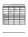
1
AUTOMATION
User manual
UM EN PROFINET SYS
PROFINET basics
AUTOMATION
User manual
PROFINET basics
01/2010
Designation:
UM EN PROFINET SYS
Revision:
00
This user manual is valid for:
PROFINET devices from Phoenix Contact
7981_en_00
PHOENIX CONTACT
UM EN PROFINET SYS
Please observe the following notes
In order to ensure the safe use of the product described, you have to read and understand
this manual. The following notes provide information on how to use this manual.
User group of this manual
The use of products described in this manual is oriented exclusively to qualified electricians
or persons instructed by them, who are familiar with applicable national standards and other
regulations regarding electrical engineering and, in particular, the relevant safety concepts.
Phoenix Contact accepts no liability for erroneous handling or damage to products from
Phoenix Contact or third-party products resulting from disregard of information contained in
this manual.
Explanation of symbols used and signal words
This is the safety alert symbol. It is used to alert you to potential personal injury
hazards. Obey all safety measures that follow this symbol to avoid possible
injury or death.
DANGER
This indicates a hazardous situation which, if not avoided, will result in death or serious
injury.
WARNING
This indicates a hazardous situation which, if not avoided, will result in death or serious
injury.
CAUTION
This indicates a hazardous situation which, if not avoided, could result in minor or
moderate injury.
The following types of messages provide information about possible property damage and
general information concerning proper operation and ease-of-use.
NOTE
This symbol and the accompanying text alerts the reader to a situation which may cause
damage or malfunction to the device, either hardware or software, or surrounding
property.
This symbol and the accompanying text provides additional information to the reader. It is
also used as a reference to other sources of information (manuals, data sheets, literature)
on the subject matter, product, etc.
PHOENIX CONTACT
7981_en_00
Please observe the following notes
General terms and conditions of use for technical documentation
Phoenix Contact reserves the right to alter, correct, and/or improve the technical
documentation and the products described in the technical documentation at its own
discretion and without giving prior notice, insofar as this is reasonable for the user. The
same applies to any technical changes that serve the purpose of technical progress.
The receipt of technical documentation (in particular data sheets, installation instructions,
manuals, etc.) does not constitute any further duty on the part of Phoenix Contact to furnish
information on alterations to products and/or technical documentation. Any other
agreement shall only apply if expressly confirmed in writing by Phoenix Contact. Please
note that the supplied documentation is product-specific documentation only and that you
are responsible for checking the suitability and intended use of the products in your specific
application, in particular with regard to observing the applicable standards and regulations.
Although Phoenix Contact makes every effort to ensure that the information content is
accurate, up-to-date, and state-of-the-art, technical inaccuracies and/or printing errors in
the information cannot be ruled out. Phoenix Contact does not offer any guarantees as to
the reliability, accuracy or completeness of the information. All information made available
in the technical data is supplied without any accompanying guarantee, whether expressly
mentioned, implied or tacitly assumed. This information does not include any guarantees
regarding quality, does not describe any fair marketable quality, and does not make any
claims as to quality guarantees or guarantees regarding the suitability for a special purpose.
Phoenix Contact accepts no liability or responsibility for errors or omissions in the content
of the technical documentation (in particular data sheets, installation instructions, manuals,
etc.).
The aforementioned limitations of liability and exemptions from liability do not apply, in so
far as liability must be assumed, e.g., according to product liability law, in cases of
premeditation, gross negligence, on account of loss of life, physical injury or damage to
health or on account of the violation of important contractual obligations. Claims for
damages for the violation of important contractual obligations are, however, limited to
contract-typical, predictable damages, provided there is no premeditation or gross
negligence, or that liability is assumed on account of loss of life, physical injury or damage
to health. This ruling does not imply a change in the burden of proof to the detriment of the
user.
7981_en_00
PHOENIX CONTACT
UM EN PROFINET SYS
Statement of legal authority
This manual, including all illustrations contained herein, is copyright protected. Use of this
manual by any third party is forbidden. Reproduction, translation, and public disclosure, as
well as electronic and photographic archiving or alteration requires the express written
consent of Phoenix Contact. Violators are liable for damages.
Phoenix Contact reserves all rights in the case of patent award or listing of a registered
design. Third-party products are always named without reference to patent rights. The
existence of such rights shall not be excluded.
How to contact us
Internet
Up-to-date information on Phoenix Contact products and our Terms and Conditions can be
found on the Internet at:
www.phoenixcontact.com
Make sure you always use the latest documentation.
It can be downloaded at:
www.phoenixcontact.net/download
Subsidiaries
If there are any problems that cannot be solved using the documentation, please contact
your Phoenix Contact subsidiary.
Subsidiary contact information is available at www.phoenixcontact.com.
Published by
PHOENIX CONTACT GmbH & Co. KG
Flachsmarktstraße 8
32825 Blomberg
Germany
Phone
+49 - (0) 52 35 - 3-00
Fax
+49 - (0) 52 35 - 3-4 12 00
PHOENIX CONTACT
P.O. Box 4100
Harrisburg, PA 17111-0100
USA
Phone
+1-717-944-1300
Should you have any suggestions or recommendations for improvement of the contents and
layout of our manuals, please send your comments to
[email protected]
PHOENIX CONTACT
7981_en_00
Table of contents
Table of contents
1
2
3
4
PROFINET (Process Field Net) ..............................................................................................1-1
1.1
PROFINET documentation ................................................................................. 1-1
1.2
Ethernet in factory automation ............................................................................ 1-2
1.3
PROFINET is an industrial Ethernet standard..................................................... 1-2
1.4
Ethernet/PROFINET development ..................................................................... 1-2
1.5
PROFINET areas of application.......................................................................... 1-4
1.6
PROFIBUS user organization promotes technology........................................... 1-5
1.7
PHOENIX CONTACT provides know-how ......................................................... 1-6
PROFINET versions ................................................................................................................2-1
2.1
PROFINET IO..................................................................................................... 2-1
2.2
PROFINET CBA ................................................................................................. 2-5
PROFINET properties .............................................................................................................3-1
3.1
Connection establishment and start-up parameterization................................... 3-1
3.1.1
Device type identification .................................................................... 3-1
3.1.2
GSD file .............................................................................................. 3-2
3.1.3
Device addressing in the field ............................................................. 3-3
3.1.4
Device parameterization during startup .............................................. 3-4
3.2
Realtime data exchange in the operating phase................................................. 3-4
3.2.1
Usual realtime communication
with RT mechanisms ........................................................................... 3-5
3.2.2
Realtime communication with RT mechanisms ................................... 3-6
3.2.3
Integrated device and network diagnostics ......................................... 3-7
3.2.4
PROFINET diagnostic mechanisms .................................................... 3-8
3.2.5
Topology detection ............................................................................. 3-9
Installing PROFINET IO devices and starting them with PC WorX ..........................................4-1
7981_en_00
4.1
Planning the PROFINET system......................................................................... 4-1
4.1.1
Planning the topology ......................................................................... 4-1
4.1.2
Determining the transmission media ................................................... 4-2
4.1.3
Using conformance classes for the planning ....................................... 4-2
4.1.4
Specifying IP addresses ..................................................................... 4-4
4.1.5
Assigning the PROFINET device name .............................................. 4-4
4.1.6
Defining update rates and estimating network loads ........................... 4-4
4.2
Configuring networks.......................................................................................... 4-7
4.2.1
Preparations with PC WorX ................................................................ 4-7
4.2.2
Configuring PROFINET devices ......................................................... 4-8
4.2.3
Integrating Ethernet devices into the project ....................................... 4-9
4.2.4
Checking the controller performance .................................................. 4-9
PHOENIX CONTACT
i
UM EN PROFINET SYS
5
A
ii
4.3
Starting up the network.....................................................................................4-10
4.3.1
Assigning device names with Netnames+ .........................................4-11
4.3.2
Observe startup behavior ..................................................................4-16
4.4
Network in operation......................................................................................... 4-17
4.4.1
Automatic start after device replacement ..........................................4-17
4.4.2
Diagnostic variables in the controller .................................................4-18
4.4.3
Diagnostics via alarm blocks ............................................................. 4-19
4.4.4
Diagnostics with Diag+ .....................................................................4-19
Wireless transmission of PROFINET data ..............................................................................5-1
5.1
PROFINET communication via WLAN................................................................ 5-2
5.2
PROFINET communication via Bluetooth........................................................... 5-3
5.3
Planning of PROFINET in wireless networks ...................................................... 5-4
5.4
Operating PROFINET in wireless networks ........................................................ 5-5
Frequently used PROFINET terms ......................................................................................... A-1
PHOENIX CONTACT
7981_en_00
PROFINET (Process Field Net)
1
PROFINET (Process Field Net)
1.1
PROFINET documentation
The PROFINET documentation is modular, providing you with optimum information.
Available
PROFINET documents
"PROFINET basics" user manual
UM EN PROFINET SYS
This manual describes PROFINET system basics.
This includes:
– PROFINET development
– PROFINET versions
– PROFINET properties
– PROFINET installation and startup
– PROFINET and wireless
Quick start guides
–
–
"Installing and starting up the starterkit 3.0" quick start guide
UM QS EN PROFINET STARTERKIT 3.0.
"Configuring INTERBUS devices in a PROFINET IO network using the example of
STEP 7"
UM QS EN PROFINET PROXY IB
Device-specific data sheets
The data sheets describe the specific properties of PROFINET devices.
This includes:
– Function description
– Ordering data and technical data
– Local diagnostic and status indicators
– Pin assignment and connection example
– Programming data/configuration data
Make sure you always use the latest documentation.
It can be downloaded at:
www.phoenixcontact.net/download
PROFINET documents
in preparation
–
–
–
7981_en_00
"Controller/device functions" application note
AH EN PROFINET CTRL DEV
"Acyclic communication" application note
AH EN PROFINET AZY KOM
"PROFINET diagnostics"
AH EN PROFINET DIAG
PHOENIX CONTACT
1-1
UM EN PROFINET SYS
1.2
Ethernet in factory automation
Increasing the productivity of machines and plants while at the same time cutting costs has
always been the driving force behind innovations in industrial automation. Machine
engineers and manufacturing companies can hold their ground in international markets all
the better if their solutions are more competitive.
Therefore production processes need to be optimized continuously. On the one hand,
productivity can be increased through a better flow of information for faster and wellfounded decisions. On the other hand, integration of machines and components into the
respective network must be simplified in order to reduce engineering and startup times.
At present company networks are characterized by complex interfaces and data exchange
mechanisms between the many island solutions in the production area and between the
factory and command level. Transparent access to machine data as would be necessary for
perfect job and production control is not possible without a great deal of effort. The aim must
therefore be to develop a uniform network structure that will guarantee that all machine and
plant parts are networked and connected to the production planning and company
command level. The key to putting this into practice is Ethernet. This transmission medium
has established itself in office communication and is already used in the industrial
environment to connect distributed machine and plant parts to each other and to higher level
systems.
1.3
PROFINET is an industrial Ethernet standard
PROFINET has established itself as an open industrial Ethernet standard for automation.
PROFINET is a network protocol on the basis of standard Ethernet so that it can be
integrated into proven Ethernet technology.
Since Ethernet is widely used in office communication, it is still possible to exchange data
worldwide between office and production levels using the world wide web (WWW). Remote
control and monitoring as well as remote maintenance are possible.
PROFINET is a consistent continuation of
– PROFIBUS DP and
– Industrial Ethernet
Experiences from both systems are integrated into PROFINET.
PROFINET
– Is automation in real time
– Uses TCP/IP and IT standards
– Allows seamless integration of fieldbuses
– Improves vertical integration
1-2
PHOENIX CONTACT
7981_en_00
PROFINET (Process Field Net)
1.4
Ethernet/PROFINET development
PROFINET will not replace PROFIBUS. 15 years of experience with PROFIBUS guarantee
a seamless transition into worldwide and established communication with Ethernet. Both
systems will coexist for many years.
The situation is as follows:
Standard Ethernet
Ethernet was widely used for office communications, various fieldbuses have been used in
the field. Using two different communications systems made it very difficult to access data
on different levels. A complex data transfer between the field and office level was required.
Ethernet could not establish itself in the field for a long time. The main reason being the
lacking realtime capability of Ethernet. Standard Ethernet is based on CSMA/CD (carrier
sense multiple access with collision detection). Depending on the system collisions may
occur on the Ethernet line. These delay the individual data packet and realtime cannot be
guaranteed.
Switched Ethernet
The situation changed fundamentally when Switched Ethernet was introduced. The fullduplex operating mode replaced CSMA/CD. And Ethernet communication became also an
option for automation technology. For years Ethernet has established in the production
plant in the operating and control area. But automation solutions used more and more PCs
and PC-based devices. More and more controllers were equipped with an Ethernet
connection. PROFINET combines these networks, some of which sometimes existed in
parallel to the automation network, in one system now. All information can be transported
over one network. The determinism for I/O signals is maintained and open TCP/IP-based
communication is not lost.
Modern systems feature direct PROFINET communication with distributed I/O.
Figure 1-1
7981_en_00
Seamless connection of the office and factory world
PHOENIX CONTACT
1-3
UM EN PROFINET SYS
1.5
Applications
There are various areas of application for PROFINET. In addition to the automotive industry
there are also reference application in water/waste water treatment, in shipbuilding, in
logistics, in process technology, in machine production, and in building automation.
Figure 1-2
Investment protection
1-4
PHOENIX CONTACT
PROFINET areas of application
PROFINET applications
The considerable investments made to date by manufacturers and users in automation
products and solutions are protected since a smooth transition from fieldbus to Ethernet
was provided. Older systems or part segments, for which Ethernet communication does not
offer any advantages, can be integrated into the PROFINET network without loosing any
information. This means investment protection for existing systems and step-by-step
access to PROFINET technology.
7981_en_00
PROFINET (Process Field Net)
1.6
PNO
PROFIBUS user organization promotes
technology
The PROFIBUS Nutzerorganisation e. V. (PNO) is a technical committee defining the
PROFIBUS and PROFINET standards and developing them further.
More than 260 manufacturers and users of the standardized communications technologies
PROFIBUS and PROFINET joined forces to advance the development and international
establishment of these technologies. The PROFIBUS user organization is a registered
association. All companies and research institutes at home and abroad may become
members. Every component manufacturer may get the protocol specification from the PNO.
IEC 61158
Since the standard has been published, the different working groups within the PNO
managed to present the most important demand in the IEC 61158 international standard.
The PROFINET technology is deeply integrated into the non-proprietary specification
processes of the PROFIBUS user organization (PNO).
Certification
PNO develops and maintains open specifications of actual communication, installation
guidelines and connector definitions as well as certification activities and user profiles.
Certification is mandatory for PROFINET and guarantees seamless interoperability of
PROFINET devices. Test and certification centers test the PROFINET devices according to
defined tests and divide them into various conformance classes. The PNO centrally
monitors test lab accreditations.
7981_en_00
PHOENIX CONTACT
1-5
UM EN PROFINET SYS
1.7
PHOENIX CONTACT provides know-how
To facilitate PROFINET users access to this technology, Phoenix Contact, Phoenix
Testlab as well as software manufacturer KW-Software to combine their know-how in the
PHOENIX CONTACT COMPETENCE CENTER (PCCC). The PHOENIX CONTACT
COMPETENCE CENTER has been accredited by the PROFIBUS user organization.
By cooperating, the three companies can offer services throughout the entire lifecycle of a
PROFINET solution.
Concept and technical
specifications
During development, the experts working at the accredited PROFINET test laboratory,
which is integrated into the Phoenix Testlab, give advise and certify products in the areas of
EMC, radio, environmental simulation and electrical device safety. All relevant standards
are considered and the product requirements deriving from these standards are
documented.
Development
The PROFINET business field at KW-Software supports device manufacturers and solution
providers during the development phase with a special portfolio of products and services.
Suitable technology components for integration into the customer’s target platform are
available for the different PROFINET device types (IO controllers, IO devices). This
integration/porting is carried out based on your requirements.
Conformance test
In October 2007, Phoenix Testlab GmbH was certified as a test lab for conducting
conformity tests for PROFINET devices. Phoenix Testlab carries out the certification test for
end products ready for series production, as well as the development-accompanying tests.
The advantage of the latter is that possible device problems that could endanger a positive
result of the entire test are detected at an early stage and can thus be corrected during
development. The device developer decides which functions are tested at what point.
Figure 1-3
1-6
PHOENIX CONTACT
PROFINET certification
7981_en_00
PROFINET (Process Field Net)
The test comprises five individual tests that have to be taken without any objection:
– State machine test to ensure repeatable testing with an expandable number of test
cases
– Hardware test, so that the IO controller of the device complies with all applicable
standards
– Interoperability test for the smooth interaction between IO devices and IO controllers
from various manufacturers
– GSD file test to check all entries in the device description file offline
– EMC validation for checking the EMC test results.
After successful testing, the customer receives an official test report which he can use to
apply for a certificate from PROFIBUS/PROFINET International (PI). For these devices, PI
issues certificates valid for three years.
User service
With the provided service, Phoenix Contact concentrates on the solution-oriented use of
PROFINET products. The focus is on configuration, start-up, service, system modernization
and training.
As one of the three PROFINET International Training Centers in Germany, the PCCC is an
authorized center for training certified PROFINET installers and engineers. In addition, the
PCCC can accredit users as a PROFINET Training Center to train engineering and service
personnel with their own certified trainers.
Figure 1-4
7981_en_00
Structure of the PHOENIX CONTACT COMPETENCE CENTER
PHOENIX CONTACT
1-7
UM EN PROFINET SYS
1-8
PHOENIX CONTACT
7981_en_00
PROFINET versions
2
PROFINET versions
The PROFINET concept is modular so that the user can select the required functions.
These functions mainly differ in the type of data exchange to meet the high demands on
speed. For PROFINET there are the versions PROFINET IO and PROFINET CBA. Both
communication paths can be used in parallel. They can be operated either separately or in
combination.
2.1
PROFINET IO
Connecting distributed
I/Os
PROFINET IO is the system to connect distributed I/Os. Thus distributed IO devices can be
directly connected to Ethernet. PROFINET IO describes the entire data exchange between
IO controllers (devices with master functions) and IO devices (devices with slave functions)
as well as parameterization and diagnostics.
PROFINET components
Since all Ethernet devices operate with equal rights in the network, the master/slave
process of fieldbus technology becomes a provider/consumer model with PROFINET IO.
The provider is the transmitter who sends data without request to the communication
partners, the consumers, who then process the data. In the framework of PROFINET IO, a
difference is made between the following roles:
– IO controller as a control system which controls the automation task. The IO controller
addresses all connected IO devices. It is generally a controller that exchanges input
and output signals with the assigned field devices. The IO controller receives all alarms
of the connected I/O devices. The IO controller also initiates the complete device
identification, the connection establishment, and the start-up parameterization of the
respective devices.
– IO device as field device that is controlled by an IO controller. An IO device consists of
several modules and submodules. An IO device is a distributed field device (e.g.,
remote I/O, drive, valve manifold, switch) that is assigned to one or more IO controllers
and that transmits not only process and configuration data, but also alarms.
– IO supervisor as an engineering tool for parameterizing and diagnosing individual IO
devices. The IO supervisor is typically based on a PC. The IO supervisor, which can be
a programming device for example, has access to all process and parameter data in
parallel to the IO controller.
7981_en_00
PHOENIX CONTACT
2-1
UM EN PROFINET SYS
Figure 2-1
PROFINET IO device
model
PROFINET components
For addressing, the IO controller uses a device model which represents the functions of one
particular field device from the viewpoint of PROFINET IO.
This view must be the same for all field devices in a network to enable communication
regardless of the manufacturer or device type. The IO device itself defines slots in which
modules can be integrated. These comprise at least one submodule that represents the
actual function.
This flexible device model is made available to the user with the device-specific GSD file.
The engineering automates signal addressing.
Figure 2-2
Fast cyclic data exchange
The device model provides the functions of the field device from the
PROFINET IO point of view.
PROFINET IO has been designed for a fast cyclic data exchange. The cyclic data telegram
to a device must not exceed the Ethernet limit of 1400 bytes user data, maximum.
Cyclic update rates that can be entered individually for each device range from 250 µs to
512 ms. It depends on each device which update rates an IO controller or an IO device
supports.
2-2
PHOENIX CONTACT
7981_en_00
PROFINET versions
Figure 2-3
PROFINET communication channels
Powerful acyclic
communication
Besides the cyclic data exchange, the communication model also allows powerful acyclic
communication that exceeds all previous fieldbus specifications. The available address
area and the parameter length are only limited by the memory areas on the IO devices and
the IO controllers.
TCP/IP communication
In addition to cyclic and acyclic PROFINET communication each device also supports
TCP/IP communication. Webserver or other IP-based technologies can be used on every
device. Other "non PROFINET devices" (such as cameras, printers, PCs) may also be
operated in the network.
Proxy concept
PROFINET IO features the integration of subsystems into a seamless communication and
diagnostic concept via a proxy. Field devices of a lower-level fieldbus system be integrated
into the PROFINET IO system via a proxy. In the PROFINET network the proxy is an IO
device, in the lower-level fieldbus system it is a master. This allows seamless integration of
existing fieldbus systems into the PROFINET network. The proxy represents the lower-level
fieldbus to the PROFINET IO system by mapping the data between both systems.
The user can access all field devices on the basis of the standardized PROFINET
specifications. Double configuration or addressing on the control system and proxy side is
not required. Data exchange, diagnostics and parameterization of the proxy are carried out
via the PROFINET protocol.
7981_en_00
PHOENIX CONTACT
2-3
UM EN PROFINET SYS
Figure 2-4
Vertical communication PROFINET IO with proxy
PROFIBUS proxy
The PROFIBUS proxy is available whenever a control systems has to be used in
combination with PROFIBUS networks. Via the proxy, integrated into the PC WorX
automation software, every Profibus device can be directly configured and diagnosed. The
signals of PROFIBUS devices are directly linked with the program variables from the
application.
INTERBUS proxy
The INTERBUS proxy acts as a link and connects an INTERBUS application to any
PROFIBUS-compatible control system. Thus, its parameterization is done using the
relevant programming tool. The integrated switch can take over the uplink to the control
system as a control cabinet switch. The integrated switch allows in distributed applications
that the proxies can be connected in a linear structure.
Robot applications used in the automotive industry are an example of the use of the proxy
technology. Communication within the robot cell is established via INTERBUS, whereas
control cabinets are networked with one another via PROFINET.
2-4
PHOENIX CONTACT
7981_en_00
PROFINET versions
2.2
PROFINET CBA
This section has been added for reasons of completion. Only PROFINET IO will be
described in following sections. This also applies to related documents, see "PROFINET
documentation" on page 1-1.
Distributed automation
solution
The component-based architecture model, PROFINET CBA (Component Based
Automation), supports the trend towards distributing automation functions to various
intelligent subsystems, since it defines both plant engineering and communication between
the subsystems and their devices.
PROFINET CBA means a function-oriented view of an automation system. The entire
system is split into individual modules which are autonomously operating subsystems.
Structure and function can be found identical or slightly modified in several systems.
PROFINET CBA is used to implement a distributed automation solution based on preassembled components and part solutions.
Communication relationships are required for interaction of the part solutions during
runtime. For this purpose, the data to be exchanged between the function units is described
while the units are programmed via the programming system and a PROFINET CBA file.
The parameter data of the individual subsystems is then imported to the link editor and the
function units linked at the click of a mouse. The modular, intelligent components from
PROFINET CBA are created in an engineering tool that may differ from one device
manufacturer to another.
PROFINET CBA is an automation concept that focuses on the following:
– Implementation of modular applications
– Controller/controller communication
Horizontal communication
PROFINET CBA supports cyclic and acyclic communication with transmission cycles of up
to 10 ms. These are very appropriate for communication between IO controllers. The
TCP/IP protocol for PROFINET CBA is suitable for operating a system with response times
in the range of 100 ms, see "PROFINET communication channels" on page 2-3.
Figure 2-5
7981_en_00
PROFINET CBA supports setting up modular, distributed machines and
system concepts
PHOENIX CONTACT
2-5
UM EN PROFINET SYS
2-6
PHOENIX CONTACT
7981_en_00
PROFINET properties
3
PROFINET properties
Communication model
PROFINET IO features a very flexible but also detailed communication model. All demands
of modern automation solutions can be met with PROFINET IO. At the same time, this
model is so flexible that devices can only use those parts of the standard that are needed
for this specific application.
In order to introduce you to the basic principles, the system will be described in the following
in terms of communication phases (connection establishment/device parameterization) and
realtime operation will be shown. Based on this basic knowledge, the contents of Section
"Installing PROFINET IO devices and starting them with PC WorX" on page 4-1 will be
easier to understand.
3.1
Connection establishment and start-up
parameterization
To understand the connection establishment, you have to deal with some marginal
conditions and the following questions:
– How is a device type identified?
– How is the device identified in the field?
– How does the device receive the communication and device-specified startup
parameters?
3.1.1
Device type identification
Each PROFINET IO field device is characterized by a device identification (device ID). The
IO controller transmits the device ID. During startup the IO device checks the device ID
transmitted by the controller against the stored ID.
The device ID is structured as follows:
Vendor ID
The Vendor ID is a 16-bit identification being a unique reference to the manufacturer. It is
assigned by the PNO to each manufacturer. A manufacturer needs this Vendor ID only
once.
Device ID
The device ID is to be used for detailed differentiation between IO devices. It is specified
manufacturer-specifically, for instance device class and device family.
Vendor ID
Device ID
Word (16 bits)
Word (16 bits)
Now every device has its own identification. It can be used, for instance, to read in a network
structure and to link it automatically with a device description that has been uniquely
assigned to this device ID. Normally, you do not have to observe this information. It is
compared between IO controller and IO device during system startup. An error message is
output and the connection establishment is aborted when the installed device does not
match the device configured offline.
7981_en_00
PHOENIX CONTACT
3-1
UM EN PROFINET SYS
3.1.2
GSD file
Simple
device description
To integrate the components needed in an automation solution, a range of information on
the device must be provided in the various engineering steps. This is done with a device
description. Each PROFINET device that has its own device ID is described by a General
Station Description (GSD) file. This file contains all data that is important for engineering as
well as for the data exchange with the IO device.
GSDML
In the engineering system, the GSD file operates as a basic for planning the configuration
of a PROFINET I/O system. The manufacturer describes the IO device properties in a GSD
file. The language used for this is GSDML (GSD Markup Language) - an XML-based
language.
XML – eXtensible Markup
Language
XML is nowadays the basis for many applications. This meta language is an abbreviated
version of the international SGML standard (Standard Generalized Markup Language), on
the basis of which one can develop such tagging languages as HTML oneself. Since SGML
is very complex and parts of the standard are seldom used, the World Wide Web
Consortium (W3C) created a simplified language in the form of XML. The basic idea of XML
is that the documents generated follow certain basic patterns in their structure in order to
make the data contained in them easier to reuse.
ISO 15745 standard
Each manufacturer of a PROFINET device must provide a GSD file. This file must also be
available and checked during the certification test. The GSD file is based on the ISO 15745
standard.
Within the framework of the PROFINET system, this description is imported into the
respective engineering system as a GSD file in XML format. Project planning and
programming is carried out in the engineering tool and then transferred to the IO controller.
Compared to a keyword-based GSD for PROFIBUS devices, the XML-based version for
PROFINET devices offers the following advantages:
– Due to the introduction of the term "submodule", it is possible to have a multidimensional description.
– Several device types may be described in a GSD file. This is due to the introduction of
the DAP (Device Access Point).
– It is possible to integrate several languages (even languages that do not use the ASCII
character set).
– All device-specific error texts are included in several languages in the GSD file.
3-2
PHOENIX CONTACT
7981_en_00
PROFINET properties
GSD file name
The names of GSD files are standardized.
GSD-[GSD Schema Version]-[Manufacturer Name]-[Product Range Name]-[Date].xml
Example:
GSD-V1.5-CompanyX-IOdevice-20090701.xml
The keywords described in brackets have the following meaning:
[GSD-Schema Version]
The GSD schema version includes the version ID of the schema used, for example, V1.5.
This version ID must correspond to the version ID in the file name of the gsdDeviceDescription-[GSD-schema version].xsd.
[Manufacturer Name]
The manufacturer name is the name of the device manufacturer. Hyphens and spaces are
permitted in the name.
[Product Range Name]
The name of the device range defines which device range is described in the GSD file.
Hyphens and spaces are permitted in the name.
[Date]
The release date is entered in the yyyymmdd format. The manufacturer guarantees that
there are no different GSD files with identical date for the same device range.
3.1.3
MAC address
Device addressing in the field
Like all other components in an Ethernet network, the PROFINET devices also have a MAC
address. This address is used to identify the devices unambiguously.
It can be found on all devices. The MAC address is a worldwide unique address. It consists
of twelve digits (hexadecimal). The first six digits of the MAC address represent the
manufacturer. For Phoenix Contact it is the ID 00 a0 45.
PROFINET name
PROFINET communication requires that every device has a PROFINET name and can be
assigned uniquely to a project. All devices in a PROFINET network can be identified with
this name. The PROFINET name must only occur once in a network. The name is stored in
a non-volatile way on the device and is available directly after power-up.
It is useful to assign a meaningful or user-friendly name to your device, since this name will
be output in the diagnostic tools in the event of diagnostics. You may also derive the device
name from the equipment identification of each device.
The IO controller searches only via the name for the IO device in the network. An error
message is output and the startup is aborted when the name cannot be found or if, by
mistake, there are two devices with an identical name in the network.
DNS syntax
Please note that the PROFINET device name is similar to the DNS syntax from the
INTERNET URL. Only lower case letters are accepted. Special characters are limited to dot
"." and hyphen "-". To facilitate readability some tools allow upper case letters. However,
they will only be displayed in the project and will not be sent to the device.
Device naming
The IO device receives its name by the so-called device naming. An engineering tool
identifies the terminal device using a flashing function or the MAC address. Afterwards, the
device name is written to the device.
7981_en_00
PHOENIX CONTACT
3-3
UM EN PROFINET SYS
IP address
It is not necessary to assign an additional IP address since it is distributed automatically
during startup using the project settings. Unlike the PROFINET name, the IP address is
stored in a volatile memory on the device and newly assigned during every device start in
comparison with the program.
3.1.4
Device parameterization during startup
After device identification the device is informed of its parameters over PROFINET. A
terminal device is passive in the network until it is addressed with its name by an IO
controller.
Communication parameters and device-specific startup parameters are transmitted to the
device. Cyclic data exchange can only start after the device received this information,
proved to be consistent and confirmed to agree with the actual hardware.
IP communication
parameters
IP parameters are part of the communication parameters. The IP parameters include IP
address, subnet mask and gateway address. Each IO device has a unique IP address. This
IP address can be used to address the device, for example, using IT services such as FTP,
HTTP provided that these functions are implemented in the device. A detailed description
of these parameters can be found in the Appendix "Frequently used PROFINET terms" on
page A-1.
Update rate
and watchdog time
The consumer/provider communication model permits a separate update rate for both
directions. You may also set a watchdog time for the device.
The update rate may have the following values. 1, 2, 4, 8, 16, 32, 64, 128, 256, 512 ms. The
GDS file determines which update rate an IO device supports. The file also has a default
update rate and a watchdog time integrated. These parameters will also be transmitted to
the device during system startup.
Startup parameters
Depending on the device structure each device may have further device-specific startup
parameters. If these parameters affect the IO device (e.g., activation of certain error
classes) they will be addressed to slot 0. Each subordinated slot or subslot may have its own
startup parameters.
This startup parameterization process takes place when an IO device is put into operation
for the first time and after every connection abort. The IO device always receives the
complete parameter record.
3.2
Realtime data exchange in the operating phase
Cyclic data exchange of PROFINET IO distinguishes between the two operating modes
PROFINET IO-RT and PROFINET IO-IRT. IRT means Isochronous Real Time and RT
means Real Time. IRT and RT can be operated in parallel in a network. Addressing and
error handling are identical. Through special methods, IRT permits a high synchronism over
the network. Therefore, PROFINET IO-IRT is used, for example, for high-deterministic
positioning tasks.
3-4
PHOENIX CONTACT
7981_en_00
PROFINET properties
3.2.1
Usual realtime communication
with RT mechanisms
Cyclic data exchange starts once the device has acknowledged the connection
establishment as positive. One Ethernet telegram is transmitted in each data direction for
every IO device.
Figure 3-1
Prioritization
Realtime communication with RT mechanisms
This data telegram uses the VLAN tag defined in IEEE 802.x with its prioritization
information. PROFINET sets the priority to the highest level 6. This flag is used in the
switches available in the network to preferentially transmit the PROFINET telegram. That
means when a PROFINET telegram and a non-PROFINET telegram with low priority arrive
at a switch at the same time, the PROFINET telegram will be transmitted first.
The received values are transmitted over the process data channel to the application or the
I/Os. This is done with the update rate set during the connection establishment. Each IO
device may have its own update rate, see also "Defining update rates and estimating
network loads" on page 4-4. There is no bus cycle time in the PROFINET system.
Status information
I/O data includes further status information. This status information shows whether the
device has an error message or reports that data is valid. The controller and the drivers
automatically evaluate this information. It will not be forwarded to the user. The validity of
data is used, for example, for a parameterizable substitute value behavior of the I/O signals.
RT communication completely covers the communication requirements of modern fieldbus
systems. Flexible startup parameterization, parallel IP communication and powerful acyclic
communication can be used in parallel on one network.
7981_en_00
PHOENIX CONTACT
3-5
UM EN PROFINET SYS
3.2.2
Realtime communication with RT mechanisms
IRT networks (Isochronous Real Time) permits a deterministic data cycle that is exact down
to a µs and additional synchronization information in particular for fast control processes.
The communication model is identical with RT communication. For example, device
addressing, startup parameterization and diagnostic mechanisms are also available.
Figure 3-2
Realtime communication with RT mechanisms (Isochronous Real Time)
The high synchronization in an IRT network is achieved with a synchronous time slot
method in the devices and switches. A clock pulse generator, the IRT-Sync-Master, defines
the clock in the network. The telegram runtime is calculated with runtime measurements
between the devices. In an IRT interval, realtime communication is carried out with each
device.
IRT network and RT network differ in two major points. First, priotization in an IRT network
is done using time slots. "Non-PROFINET data traffic" is only initiated or forwarded in the
TCP/IP phase. If a "non-PROFINET telegram" has not reached its destination when the IRT
phase starts, it is buffered in the device reached.
Second, every PROFINET telegram in the network is planned. For this, transmit lists are
sent to every IRT device in the startup phase, so that the forwarding of the message is
equally deterministic. Thus, PROFINET achieves a jitter accuracy of less than 1 µs.
Since Phoenix Contact controllers do not yet support IRT, IRT will not be described further
in this manual. Please check in the relevant data sheets whether I/O or infrastructurecomponents support IRT.
3-6
PHOENIX CONTACT
7981_en_00
PROFINET properties
3.2.3
Integrated device and network diagnostics
The PROFINET system features comprehensive and standard device and network
diagnostics. Apart from PROFINET diagnostic mechanisms, standards such as SNMP and
HTTP can also be integrated into the diagnostics concept.
Figure 3-3
Device diagnostics and network diagnostics with PROFINET
http
Web-based diagnostics can be integrated into the device since every device has an IP
address. The user can take a browser to go to the terminal device and perform local
diagnostics. Web-based diagnostics is almost always available on infrastructure
components. In the terminal devices it depends on the diagnostic depth the device can
report. Web-based diagnostics is optional in a PROFINET network.
SNMP
SNMP (Simple Network Management Protocol) is a worldwide established Ethernet
standard. Devices can send SNMP traps (alarms) to central stations, which in turn display
messages or request devices to provide additional information via SNMP. PROFINET
defines SNMP entries of MIB2 as mandatory, see also "Frequently used PROFINET terms"
on page A-1.
7981_en_00
PHOENIX CONTACT
3-7
UM EN PROFINET SYS
3.2.4
PROFINET diagnostic mechanisms
Within the framework of PROFINET diagnostics, IO devices report an error cyclically using
I/O transfer or acyclically using alarms. For example, in the event of undervoltage at the
actuator supply of an IO device, an incoming alarm is sent to the control system. If the error
has been eliminated, the control system is informed with a cleared alarm.
Diagnostic alarm
and maintenance alarm
Alarms are divided into two groups to satisfy the ever increasing importance of preventive
diagnostics:
– Usually, error states are transmitted as diagnostic alarms with corresponding
parameters.
– Wear indication or similar information can be coded as maintenance alarms.
Figure 3-4
PROFINET diagnostic mechanisms
A PROFINET diagnostic tool only needs the manufacturer and device ID to find the file and
display the error message in plain text. The more precise the error message given by the
device, the more exact diagnostic locations can be displayed in the control or engineering
system.
Diag+
3-8
In the automation solution from Phoenix Contact, the Diag+ software tool collects all
diagnostic information, presents it clearly in a topology view or a tree structure and displays
error causes in various languages in plain text. Diag+ is an integral part of the PC WorX
programming environment. However, it can also be directly integrated into the visualization
as an independent ActiveX solution.
PHOENIX CONTACT
7981_en_00
PROFINET properties
3.2.5
LLDP
Topology detection
PROFINET uses the LLDP (Link Layer Discovery Protocol) to display the precise location
of diagnostic messages in an open, flexibly cabled network. LLDP is a manufacturerindependent Layer 2 protocol, defined in accordance with the IEEE-802.1AB standard and
can be used to exchange information between neighboring devices. Devices exchange
their names and port numbers with the neighboring components via LLDP when the
connection is being established. If all devices used in the network support the protocol, an
accurate topology view can be presented in the diagnostic tool. This way, error messages
can be displayed directly on the device or port.
A software component called LLDP agent runs on every device supporting LLDP. The LLDP
agent transmits periodically information about itself and constantly receives information
from neighboring devices. This happens independently and therefore the LLDP is called a
"one-way-protocol" which does not establish communication to other protocols.
LLDP_EXT_MIB
Information received via LLDP is stored locally on every device in a data structure called
Management Information Base (MIB). SNMP can be used to access this information in the
LLDP_EXT_MIB.
Figure 3-5
7981_en_00
Topology detection
PHOENIX CONTACT
3-9
UM EN PROFINET SYS
3-10
PHOENIX CONTACT
7981_en_00
Installing PROFINET IO devices and starting them with PC WorX
4
Installing PROFINET IO devices
and starting them with PC WorX
This section describes the planning phase of your system and device replacement during
operation.
To optimize your system startup, please proceed as described in the following.
4.1
Planning the PROFINET system
The PROFINET network is an open network which may also include Ethernet devices.
Therefore, planning a PROFINET network is very important. This includes unambiguous IP
addresses, definition of name assignment and a first estimation of the network load.
4.1.1
Flexible
network structures
Planning the topology
PROFINET offers a flexible topology. The PROFINET installation follows the system which
means that the topology is not specified by the technology. There is a point-to-point
connection between the devices. The basic elements of the topology are always line
structures or branches. You may create any topology using these basic elements. A special
form of the line structure is the ring structure in which line from the last device is led back to
the beginning of the line where it closes the ring. Topologies can be mixed at any time.
I/O devices with two ports permit to set up line structures. A switch with the corresponding
number of ports is required when several devices are to be grouped together at one point.
Figure 4-1
7981_en_00
PROFINET topology example
PHOENIX CONTACT
4-1
UM EN PROFINET SYS
4.1.2
Determining the transmission media
After you have planned the topology you determine the transmission media. PROFINET
devices mostly use copper connections. This permits cable lengths up to 100 m. You may
use optical transmission media when longer distances have to be covered. Fiber optics are
resistant to electromagnetic interference and partly allow for larger network sizes than
copper cables. The maximum segment length between two PROFINET devices is up to
14 km for fiber-optic cables.
If mobile devices are to be addressed using wireless technology, you have to design the
wireless networks accordingly. For additional information, please refer to Section "Wireless
transmission of PROFINET data" on page 5-1.
Transmission media
Depending on the requirement a PROFINET network permits to
– Communicate over present networks on the basis of copper cables
– Use fiber-optic cables that are resistant to EMI and permit larger network dimensions
– Switch - in the event of an error - the communication path to an intact branch of the ring
structure using a standardized method
– Implement wireless data transmission over WLAN and Bluetooth
4.1.3
Using conformance classes for the planning
To aid your PROFINET network planning, the PROFINET user organization divided the
PROFINET scope of functions into conformance classes (CC). The aim was to simplify the
decision criteria for system operators when using PROFINET IO. By defining a
conformance class you can may select field devices and bus components that feature
clearly defined minimum properties. This is important to guarantee interoperability of all field
devices involved in communication. All conformance classes include by default basic
functions such as cyclic and acyclic data exchange or alarms.
The minimum requirements for three conformance classes (CC-A, CC-B, CC-C) have been
defined from the system operator's point of view. In addition to the three application classes
there are additional definitions for
– Device types
– Type of communication
– Transmission medium used
– Redundancy behavior
Conformance Class A
(CC-A)
Uses the infrastructure of a present Ethernet network and integrates PROFINET basic
functions. All IT services can be used without limitations. Typical applications can be found
in production engineering, building or process automation. Only this class permits wireless
communication.
Conformance Class B
(CC-B)
In addition to CC-A, the CC-B scope of functions allow for an easy and convenient device
replacement without engineering tool. A media redundancy protocol for TCP(UDP)/IP data
is integrated to increase data security. Field devices of CC-B have and integrated 2-port
switch. Typical applications are automation systems and higher-level machine control with
low demands on a deterministic data cycle.
Conformance Class C
(CC-C)
In addition to CC-B, the CC-C scope of functions allows for a high-precision, deterministic
data transmission including synchronous applications. The integrated media redundancy
allows for a bumpless switch-over of I/O data traffic when an error occurs. Typical
applications can be found, for instance, in the field of motion control.
4-2
PHOENIX CONTACT
7981_en_00
Installing PROFINET IO devices and starting them with PC WorX
The following table provides an overview of the properties of the conformance classes.
Feature
CC-A
CC-B
CC-C
Realtime protocols
RT
RT
RT/IRT
Certified device types
IO controller
IO device
IO supervisor
IO controller
IO device
IO supervisor
IO controller
IO device
IO supervisor
Use of standard Ethernet
infrastructure
Yes, no certification required
– Switches acc. to 802.3
– WLAN and Bluetooth
Access Point/Clients
Yes,
but switches are also IO
devices and therefore need
to be certified
No,
PROFINET IO-IRT-capable
hardware required in all
switch components
Transmission media
Copper (100 Mbps)
FO (100 Mbps)
Wireless (WLAN 2.4 GHz /
5 GHz, Bluetooth)
Copper (100 Mbps/s)
FO (100 Mbps)
Copper (100 Mbps/s)
FO (100 Mbps)
Bussynchronous
applications
No
No
Yes
PROFINET cabling
guideline valid
No
Yes
Yes
Functions
–
Topology detection
No
Yes
Yes
–
Representation in the
network management
via SNMP
No
Yes
Yes
Redundancy mechanisms
–
Media redundancy
meshed with
RSTP/switch-over 2 s
Optional
Optional
No
–
Media redundancy
MRP ring/
switch-over 200 ms
Optional
Optional
No
–
Media redundancy
No
MRP ring/
bumpless switch-over
No
Optional
7981_en_00
PHOENIX CONTACT
4-3
UM EN PROFINET SYS
4.1.4
Specifying IP addresses
Every device in a PROFINET network has an IP address. The device receives this address
from the control system when the system is started. That means that devices that should not
be accessed over TCP/IP (e.g., a simple I/O station) also require an IP address. Other
devices in the network (operating PCs, technology controllers, cameras,...) also have an IP
address. Every IP address in a network must only be assigned once.
The IP parameters include the actual IP address, the subnet mask and the gateway
address. These terms are explained in the Appendix "Frequently used PROFINET terms".
When you plan your PROFINET network you define the IP addresses of the devices on the
network. If there are recurring structures, you may define IP addresses in the subnet
according to your own rules. For example, I/Os in the network always have addresses 100
to 125 or the "Supply" system part has always addresses 50 to 59.
When networking higher-level networks, the planner receives the IP parameters (gateway
address, subnet mask and IP address range) directly from a responsible person for the
network. Normally, the responsible person for automation can use any address of the IP
address range.
4.1.5
Assigning the PROFINET device name
The PROFINET device name is an important information for the control system. The IO
controller can find the end device only through its name. The name of the device output
even in the event of diagnostics. It is therefore only useful to define a name space when you
plan the system. For this you may use equipment identifications or device functions
("Motor1_Rotating_tower").
4.1.6
Defining update rates and estimating network loads
PROFINET distinguishes itself in one important point from other popular fieldbus systems.
There is no bus cycle in which, for instance, the slowest device sets the transmission speed.
For each device you may determine an individual update rate for the input and output
direction.
Update rate and telegram length of a device determine the network load of this device. If you
are not sure about the network load of your system, just calculate the network load for the
busiest path on the network. In most cases this is the path to the controller. If additional
network traffic on the control level and, for instance, additional network traffic for camera
systems is to be expected, you have to estimate these paths separately.
4-4
PHOENIX CONTACT
7981_en_00
Installing PROFINET IO devices and starting them with PC WorX
The following table shows how much network load PROFINET devices with up to 40 bytes
user data generate.
Number
of
devices
Update rate in ms
1
2
4
8
16
32
64
128
256
512
1
0.80%
0.40%
0.20%
0.10%
0.05%
0.025%
0.013%
0.006%
0.003%
0.002%
2
1.60%
0.80%
0.40%
0.20%
0.10%
0.050%
0.025%
0.013%
0.006%
0.003%
3
2.40%
1.20%
0.60%
0.30%
0.15%
0.075%
0.038%
0.019%
0.009%
0.005%
4
3.20%
1.60%
0.80%
0.40%
0.20%
0.100%
0.050%
0.025%
0.013%
0.006%
5
4.00%
2.00%
1.00%
0.50%
0.25%
0.125%
0.063%
0.031%
0.016%
0.008%
8.00%
4.00%
2.00%
1.00%
0.50%
0.250%
0.125%
0.063%
0.031%
0.016%
16.00%
8.00%
4.00%
2.00%
1.00%
0.500%
0.250%
0.125%
0.063%
0.031%
24.00%
12.00%
6.00%
3.00%
1.50%
0.750%
0.375%
0.188%
0.094%
0.047%
32.00%
16.00%
8.00%
4.00%
2.00%
1.000%
0.500%
0.250%
0.125%
0.063%
40.00%
20.00%
10.00%
5.00%
2.50%
1.250%
0.625%
0.313%
0.156%
0.078%
80.00%
40.00%
20.00%
10.00%
5.00%
2.500%
1.25%
0.625%
0.313%
0.156%
...
10
...
20
...
30
...
40
...
50
...
100
7981_en_00
PHOENIX CONTACT
4-5
UM EN PROFINET SYS
The following table shows how much network load PROFINET devices with up to 100 bytes
user data generate.
Number
of
devices
Update rate in ms
1
2
4
8
16
32
64
128
256
512
1
1.60%
0.80%
0.40%
0.20%
0.10%
0.050%
0.025%
0.013%
0.006%
0.003%
2
3.20%
1.60%
0.80%
0.40%
0.20%
0.100%
0.050%
0.025%
0.013%
0.006%
3
4.80%
2.40%
1.20%
0.60%
0.30%
0.150%
0.075%
0.038%
0.019%
0.009%
4
6.40%
3.20%
1.60%
0.80%
0.40%
0.200%
0.100%
0.050%
0.025%
0.013%
5
8.00%
4.00%
2.00%
1.00%
0.50%
0.250%
0.125%
0.063%
0.031%
0.016%
16.00%
8.00%
4.00%
2.00%
1.00%
0.500%
0.250%
0.125%
0.063%
0.031%
32.00%
16.00%
8.00%
4.00%
2.00%
1.000%
0.500%
0.250%
0.125%
0.063%
48.00%
24.00%
12.00%
6.00%
3.00%
1.500%
0.750%
0.375%
0.188%
0.094%
64.00%
32.00%
16.00%
8.00%
4.00%
2.000%
1.000%
0.500%
0.250%
0.125%
80.00%
40.00%
20.00%
10.00%
5.00%
2.500%
1.250%
0.625%
0.313%
0.156%
-
80.00%
40.00%
20.00%
10.00%
5.000%
2.500%
1.250%
0.625%
0.313%
...
10
...
20
...
30
...
40
...
50
...
100
The resulting cumulated network load determines the performance of your controller. If the
controller cannot process these network loads, reduce the devices update rates or use a
more powerful controller. You can also distribute the controller program to several
controllers.
The following table shows you guide values when using different controllers. If you need an
exact result you can insert the number of devices in the PC WorX project. If the controller
performance is exceeded, an error message is output when the project is compiled.
4-6
PHOENIX CONTACT
Controller
Network loads
Maximum number of devices
ILC 3xx
< 5%
100
RFC 4xx
< 10%
100
SMAX 4xx
< 15%
100
7981_en_00
Installing PROFINET IO devices and starting them with PC WorX
4.2
Configuring networks
Now transfer your planning results to the prepared project.
4.2.1
Preparations with PC WorX
Communication
In the "Extras/Profinet Configuration..." menu in PC WorX select the network card for your
computer that is to be used for communication.
Creating a project
If a project does not yet exist, create it first under PC WorX. Select the "New Project..."
command from the "File" menu.
Then select the IO controller.
Project parameters
In the bus configuration workspace you can adapt the project information to the project.
After you have selected the node for the IO controllers in the "Bus Structure" window, you
can change, for instance, the IP settings in the "Device Details" window.
Also prepare the PC for communications by selecting its IP parameters in such a way that it
can communicate with the connected network.
Importing third-party
devices
Devices which are not yet included in the device catalog may be imported with the "Import
GSD File" function (right-click). The device will then be added to the catalog with the
company designation.
For detailed information, please refer to the "Installing and starting up the starterkit 3.0"
quick start guide UM QS EN PROFINET STARTERKIT 3.0. It can be downloaded at:
www.phoenixcontact.net/download
7981_en_00
PHOENIX CONTACT
4-7
UM EN PROFINET SYS
4.2.2
Configuring PROFINET devices
In this step you drag PROFINET IO devices from the device catalog to the PROFINET node
of the controller (double-click/return or drag & drop). The corresponding settings such as
device name, IP address and update rate/monitoring time are automatically set with default
values and should be changed to the planned name and address on the "PROFINET
Settings" tab in the "Device Details" view.
In addition to the update rate you may set a monitoring time for each connection, so that a
connection is aborted when this time is exceeded. A multiple of the transmission rate is set.
The smallest setting is "3".
The following additional device parameters affect the system behavior of the controller and
can be set separately for each IO device.
– Drive BF
– Log connection state
– Operate with differences in configuration
For detailed information, please refer to the "Installing and starting up the starterkit 3.0"
quick start guide UM QS EN PROFINET STARTERKIT 3.0. It can be downloaded at:
www.phoenixcontact.net/download
4-8
PHOENIX CONTACT
7981_en_00
Installing PROFINET IO devices and starting them with PC WorX
4.2.3
Integrating Ethernet devices into the project
To ensure that IP addresses are assigned only once in the network, Ethernet devices such
as PCs or Ethernet infrastructure components may be integrated into the project as
placeholders. To do so, you must drag these devices from the device catalog to the tree
level in parallel to the controller. Ethernet and wireless infrastructure components from
Phoenix Contact can be found directly under the FL (Factoryline) device range. You can use
the Windows PC from the "Generic" folder as a placeholder for other Ethernet devices.
Figure 4-2
4.2.4
Placeholder: Windows PC device
Checking the controller performance
You have to compile the project once to check the performance of the selected controller. If
no other error message than "Program missing" is output the basic specifications of the
controller have not been exceeded.
7981_en_00
PHOENIX CONTACT
4-9
UM EN PROFINET SYS
4.3
Starting up the network
First, all device names have to be written to the devices to allow the controller to start up the
network. This is called "device naming" and can be done from PC WorX or with other tools.
The device should be named when it is electrically installed. At this point there is a unique
assignment to the device and you can name it without mixing it up with other devices.
You can use the MAC address printed on the device to identify the device unambiguously.
Additional certainty is provided with the "Flashing". Single, addressed devices flash with
their display instruments such as LEDs, when they are being searched with a PROFINET
engineering tool in the system.
4-10
PHOENIX CONTACT
7981_en_00
Installing PROFINET IO devices and starting them with PC WorX
4.3.1
Assigning device names with Netnames+
The Netnames+ tool from the AUTOMATIONWORX Software Suite offers an easy option
for naming a device.
You find the tool in the program menu under PHOENIX CONTACT-> AUTOMATIONWORX
Software Suite ….-> Service programs. After you have selected the network card, this tool
provides a fast overview of all PROFINET IO devices present in the subnetwork, even
without a PCWorX project. You can set names and write several names simultaneously.
You can also set IP addresses to address, for example, web pages of the device in the
startup phase.
The import list offers a special function. With the help of an easy import list, Netnames+ can
import all names from a planning tool. These names can be allocated to the identified
devices using drag & drop. The device names no longer have to be entered manually.
Figure 4-3
Changing device names
A detailed description of Netnames+ functions can be found in the online help.
7981_en_00
PHOENIX CONTACT
4-11
UM EN PROFINET SYS
Reading the configuration
Start PC WorX and create a new project or open an existing project, see "Preparations with
PC WorX" on page 4-7. In the "Bus Structure" window of the bus configuration workspace
select the PROFINET node for the control system. Select "Read PROFINET..." in the
context menu. This function can be used to locate all PROFINET devices in the network.
Figure 4-4
Read PROFINET
All the connected PROFINET devices are displayed.
4-12
PHOENIX CONTACT
7981_en_00
Installing PROFINET IO devices and starting them with PC WorX
Figure 4-5
Inserting PROFINET devices
You can select devices from this list and insert them into the current project with the "Insert"
button.
In order to limit the search results, different options are available:
No constraints
All devices that are available in the network are listed.
Unnamed
All those devices that do not yet have a PROFINET device name are listed.
Not in project
All those devices that are not included in the project are listed.
The devices are uniquely assigned with their MAC address. You also have the option of
letting the LEDs flash for a selected device. To do so, select a device and click the "Flashing
On" button.
A device name is created automatically when the device is transferred to the project and the
device is named. You can also assign another, individual name.
7981_en_00
PHOENIX CONTACT
4-13
UM EN PROFINET SYS
Assigning a name
manually
If a project has already been created, it includes all communication settings and device
names. These must be assigned to the existing devices.
Select the node of the PROFINET device to which a device is to be assigned in the "Bus
Structure" window. The "Device Details" window shows under "PROFINET Stationnames"
all PROFINET devices available on the network.
Figure 4-6
4-14
PHOENIX CONTACT
Display of PROFINET devices
7981_en_00
Installing PROFINET IO devices and starting them with PC WorX
In order to limit the search results, different options are available here too:
No constraints
All devices that are available in the network are listed.
Unnamed
All those devices that do not yet have a PROFINET device name are listed.
Not in project
All those devices that are not included in the project are listed.
Same type
Only devices that correspond to this device type are listed.
The MAC address is used to identify the devices in the network unambiguously. Select the
desired device and click the "Assign Name" button. The device is named with the
PROFINET name.
An other option to identify devices in a system is the "Flashing" function. To do so, select a
device from the network and click the "Flashing On" button. You can now find the device in
the system with help of the flashing LEDs.
You have to repeat these steps for every device in the project.
7981_en_00
PHOENIX CONTACT
4-15
UM EN PROFINET SYS
4.3.2
Observe startup behavior
Starting up the controller is the easiest way to check
– The controller is correctly parameterized
– The I/O devices have the right name
– There are double names or double IP addresses in the system.
Compile the project with the bus configuration. There will be a warning message if there is
no application program. You can ignore this message.
Make sure that the controller has the IP address that was set in the project. Start the project
control dialog via the menu bar.
If the message "Timeout" appears after 10 seconds, the project and device addresses do
not match. It is also possible that the IP address of the computer has not been set correctly.
The controller can be reset from the project control dialog. Existing projects will be deleted.
Start the download and perform a cold reset. Afterwards the BF LEDs must go out on all
devices.
To access the network status from the program, the following system variables are mapped
in the global variables of the programming environment. Activate the "Debug On" operating
mode and the values of these variables will be displayed.
Global variable
Description
PNIO_CONFIG_STATUS_ACTIVE
Connection to these devices is being established or has been completed.
PNIO_CONFIG_STATUS_READY
The connection establishment to the devices has been completed.
If you need more detailed information, call the Diag+ diagnostic tool from PC WorX under
View-> Diag+. Here you connect explicitly to a controller and receive further information,
see Section 4.4.3 on page 4-19.
4-16
PHOENIX CONTACT
7981_en_00
Installing PROFINET IO devices and starting them with PC WorX
4.4
4.4.1
Network in operation
Automatic start after device replacement
PROFINET addresses each device with a name. If the device is exchanged, its name must
be transferred to the new component In the PROFINET system, the control system detects
the device replacement with the help of the topology information and automatically writes
the name of the replaced component to the replacement device within seconds. However,
using a memory card or starting a software for manual name assignment takes more time.
Figure 4-7
Automatic start after device replacement
However, some basic requirements must be met so that topology detection functions
properly:
– It is mandatory that the PROFINET devices support LLDP.
– To be able to use the automatic name assignment when a device is replaced, the
topology must not be changed by the replacement. That means that a defective device
can only be replaced by an identical version and at the same spot.
It is important that IO controller operation is not interrupted after the device failure. If it is
interrupted, information on neighborhood detection will be lost. Then you must name the
device manually with the PROFINET name.
NOTE:
If devices of a system are replaced with one another, this will cause problems. All names
are defined in the project, and so no device has been added and no device is missing. The
system recognizes this status as a changed topology. PROFINET communication is
started without having changed the device names.
7981_en_00
PHOENIX CONTACT
4-17
UM EN PROFINET SYS
4.4.2
Diagnostic variables in the controller
PROFINET IO offers very detailed diagnostic information about every device down to the
channel.
Diagnostic states are important for system operation. If error messages occur, the process
must be stopped in case of doubt. AUTOMATIONWORX controllers offer the following
status information for the PROFINET network.
Global variable
Type
Description
PNIO_SYSTEM_BF
BOOL
An error occurred in the PROFINET network, that means, there is no
connection to at least one configured device. This value is not set if the
"Drive BF" parameter was set to FALSE for a device. This device is
removed from connection monitoring.
PNIO_SYSTEM_SF
BOOL
At least one device reported a system error (diagnostic alarm or
maintenance alarm).
PNIO_DIAG_AVAILABLE
BOOL
At least one device reported a diagnostic alarm with an active
connection.
PNIO_MAINTENANCE_DEMANDED BOOL
At least one device reported the "maintenance request" alarm with an
active connection.
PNIO_MAINTENANCE_REQUIRED
At least one device reported the "maintenance demand" alarm with an
active connection.
BOOL
If one of these values is set, it can be decided from the program now whether to continue or
stop system operation. System errors of the type maintenance demand or maintenance
request can, for example, only lead to a message to the service personnel. This message
includes error location, error reason and priority.
If the application is to monitor every device for diagnostics, the automatically generated
signals of the PNIO_DATA_STATE structure can be also be used.
Global variable
Description
PNIO_DATA_VALID
The application program must receive information on whether a PROFINET IO device is supplying
valid data or not. For this reason, the "PNIO_DATA_VALID" process data item exists on every
PROFINET IO device.
Only if this bit is set does the PROFINET IO device supply valid data and all other process values
are valid.
PNIO_DATA_DIAG
4-18
If this bit is set, no device diagnostics is present.
PHOENIX CONTACT
7981_en_00
Installing PROFINET IO devices and starting them with PC WorX
4.4.3
Diagnostics via alarm blocks
To display the error messages from the previous section in a reasonable way on the
operating level, the error cause can be read from every device with the RALRM block.
This block needs the ADDRESS_TO_ID function to identify the terminal device. The
RALRM block can retrieve the diagnostic message with the communication ID. Unlike
Diag+ the block does not receive error texts. It outputs binary information only. This includes
slot number, subslot number, channel number or error cause.
Figure 4-8
Alarm block
For more information on the alarm blocks, please refer to the PC WorX online help.
4.4.4
Diagnostics with Diag+
If an error occurs, the Diag+ tool can be started from PC WorX or from another program at
any time. First, Diag+ must establish connection to the controller, then various diagnostic
views can be called.
PROFINET diagnostics
PROFINET diagnostics displays all PROFINET devices in a tree structure. Devices shown
in red have an error. If the device is accessed, all slots of the device will be displayed with
the exact error location an type. The error cause will be given as text information when the
GSDML file of the terminal device is available on this computer. This view displays the
current error status. An error history can be found in the diagnostic archive.
Ethernet topology
The Ethernet topology displays the specified network status. PROFINET and Ethernet
devices have equal rights. By switching to the "Show Accessibility" function you get an
overview of the device connections.
Diagnostics archive
The diagnostic archive collects all error messages arriving on the controller - not only
PROFINET. A time stamp and comprehensive filter criteria can be used to display certain
processes at a later date. The archive is a ring buffer in which the oldest information is
overwritten after the limits have been reached.
7981_en_00
PHOENIX CONTACT
4-19
UM EN PROFINET SYS
4-20
PHOENIX CONTACT
7981_en_00
Wireless transmission of PROFINET data
5
Wireless transmission of PROFINET data
Data transmission via cables is cost-effective, safe, and reliable if the cable installation is
static. Industrial production features more and more movable components in production.
Electromechanical installation solutions such as collector wires or drag chains are not only
expensive, but they wear caused by constant strain. Communication errors may occur that
reduce the availability of the system and require time-consuming maintenance work.
Cost-effective and reliable
alternative
For many users, new options and considerable cost benefits can be achieved thanks to the
transparent and reliable transmission of PROFINET via Bluetooth or WLAN. Wireless
communication is a cost-effective and reliable alternative to this. Since most of the wireless
standards have been developed for wireless Ethernet communication, PROFINET can also
be transmitted easily and transparently. The PNO has specified Bluetooth (IEEE 802.15.1)
and WLAN (IEEE 802.11) for PROFINET communication.
Wireless standard
properties
Bluetooth and WLAN have different technical features. This is why they address different
application fields.
WLAN
–
–
–
–
Set-up of extensive networks with many devices
High data throughput of up to 54 Mbps
High mobility of the devices owing to fast roaming from
access point to access point
Good integration into IT network structures
Bluetooth
–
–
–
–
–
7981_en_00
Wireless connection of a small number of devices to local control systems
Fast and efficient transmission of small data packets
Reliable communication in rough industrial environment
Excellent coexistence with WLAN networks
Parallel operation of many Bluetooth networks is possible
PHOENIX CONTACT
5-1
UM EN PROFINET SYS
5.1
PROFINET communication via WLAN
Since the signal is spread across about 22 MHz, WLAN proves to be very resistant against
interferences. Data rates of up to 54 mbps (gross) can be attained depending on the quality
of the transmission signal. A 2.4 GHz frequency band provides three WLAN channels,
whereas the still rarely used 5 GHz frequency band provides 18 WLAN channels which can
be used simultaneously. The WLAN Access Point from Phoenix Contact which has been
specially developed for industrial automation offers quick roaming functions essential in
mobile transport applications, among other things. Besides, data streams can be prioritized
to give priority to the transmission of time-critical data.
Figure 5-1
Communication via WLAN
WLAN (Wireless Local Area Network) standards operate on the Physical Layer of the
ISO/OSI reference model, which means that PROFINET RT frames can be transmitted
using a transparent protocol.
Although WLAN data rates are available in ranges up to 54 Mbps, the net data rate is only
around 50 percent due to the large overhead. If, instead of large data packets of 1500 bytes,
smaller, automation-typical packets are transmitted, the data throughput deteriorates
considerably. However, this disadvantage is compensated by the benefits of
standardization and low costs.
PROFINET is designed for a cable-based switch LAN with 100 Mbps full duplex
transmission. WLAN is a shared LAN with a current maximum net data rate of 6 Mbps
(WLAN 802.11b) and 25 Mbps (WLAN 802.11g) respectively for half duplex transmission.
PROFINET RT frames can be transmitted transparently, however the realtime speed of a
cable-based network cannot be achieved. If the WLAN network is available exclusively to
only one device, short cyclic transmission times of 4 ms to 8 ms can be implemented with a
low jitter. In the event of several devices, a maximum response time cannot be guaranteed
due to the CSMA/CA (Carrier Sense Multiple Access with Collision Avoidance) access
method used. With WLAN extension 802.11e, which is currently being specified,
mechanisms will soon be available that will support a defined Quality of Service (QoS) for
the wireless connection.
As a public medium is used to transmit data in wireless communication, a wide range of
interference can occur. Since WLAN transmits in the 2.4 GHz range, transmission is not
disturbed by interference fields, which occur in the kHz and MHz ranges, e.g., from arc
welding, frequency inverters or switching operations. In addition, the signal is spread over
5-2
PHOENIX CONTACT
7981_en_00
Wireless transmission of PROFINET data
a larger frequency range using the Direct Sequence Spread Spectrum (DSSS) method.
However, a WLAN 802.11b/g system permanently occupies 22 MHz of the frequency range
of just 83 MHz. Since there can be no overlapping frequencies for interference-free WLAN
communication, only three of the 13 European WLAN channels can be used
simultaneously. In the 5 GHz band, up to 12 channels are available.
5.2
PROFINET communication via Bluetooth
Bluetooth is a flexible wireless technology and is used, in particular, in small local networks
with up to seven devices. The frequency hopping method in which the transmission channel
switches up to 1600 times per second, makes the wireless standard extremely rugged.
Bluetooth was designed for efficient transmission of small data packets so that control
signals can be transmitted quickly and reliably. PROFINET update times of 8 ms or 16 ms
are thus possible. Since WLAN channels can be hidden via configuration, Bluetooth
components from Phoenix Contact can be operated simultaneously with WLAN networks
without problems.
Figure 5-2
Communication via Bluetooth
Possible areas of application:
– As an access point for seven devices (1)
– As an Ethernet client adapter (2)
– As a serial port adapter (3)
– As a protocol-transparent point-to-point bridge (4)
Bluetooth is a universal wireless technology, which features a rugged and reliable
transmission technology. This is mainly due to its use of broadband transmission over the
entire 2.4 GHz frequency band using the Frequency Hopping Spread Spectrum (FHSS)
method. Here, a total of 79 hopping channels are changed in a pseudo random sequence
up to 1600 times per second. If necessary, faulty data telegrams are resent using another
channel without a notable time delay. Thanks to the adaptive frequency hopping method of
Bluetooth Version 1.2, channels that are occupied by other wireless systems or those that
7981_en_00
PHOENIX CONTACT
5-3
UM EN PROFINET SYS
are frequently subject to interference are detected automatically and removed from the
hopping sequence. This increases reliability and ensures interference-free coexistence
with a WLAN 802.11b/g system.
Bluetooth offers various profiles and protocols for different applications. Thanks to the low
protocol overhead, the available bandwidth is used effectively. With a gross data rate of
1 Mbps - which corresponds to a net rate of around 750 kbps - Bluetooth has a lower data
throughput than WLAN. This is sufficient for the wireless connection of a small number of
control systems or automation components, which usually only transmit a few bytes of data.
If, for example, 100 bytes of data have to be exchanged cyclically in both directions after
16 ms, the required net data rate is only 100 kbps.
Bluetooth can use the frequency band efficiently thanks to the FHSS method. This is why
Bluetooth systems can be operated in large numbers locally and in parallel, and can coexist
with WLAN systems. However, in large industrial halls, a full coverage wireless signal can
only reach several devices with good data throughput over WLAN with some difficulty. This
is because the three WLAN channels limit the option of improving the wireless signal by
increasing the density of access points. If roaming is not required between the access
points, it is easier to create several small Bluetooth networks.
5.3
Planning of PROFINET in wireless networks
Wireless simulation tool
Every wireless network needs a wireless field simulation which takes into account not only
the number of access points and devices but also building automation conditions. The
Wireless Simulation Tool will help you in collecting the necessary information. The Wireless
Simulation tool can be used for both the WLAN system (2.4/5 GHz) and the Bluetooth
system. It allows to simulate walls, machines, control cabinets, as well as device positions
with the antennas used. This simulation software for support when planning wireless
systems in the industrial environment can be found at www.phoenixcontact.com.
IP address
for wireless infrastructure
When planning the communication of a PROFINET network with integrated wireless paths,
please note that access points and clients also have an IP address. This IP address must
be taken from the planning phase of the system to be able to diagnose the devices with
Web-Based Management.
Update rate
Due to the reduced net wireless data rate, devices after the wireless path cannot be
operated with a 1 ms update rate. Typical values start with 8 ms for one device.
Please refer to the data sheets of the access points and clients for further information, in
particular when using several devices.
5-4
PHOENIX CONTACT
7981_en_00
Wireless transmission of PROFINET data
5.4
Connection
monitoring
Operating PROFINET in wireless networks
The wireless networks are transparent for the PROFINET connection monitoring. IO
controller or IO device do not know that data is transferred over a wireless path.
If connection aborts occur, you should either change the update rate, increase the
watchdog time, or check the web page of the wireless components for diagnostic
information.
Figure 5-3
Topology information
Bluetooth device web page
If there is only one device after the access point, this wireless path is transparent and
assessed like a cable. The topology information remains unique and the replacement of the
PROFINET device after the wireless path still operates automatically.
If there are several devices after a wireless access point, the topology information is no
longer unique. The "Automatic topology-based device replacement" function is no longer
possible.
7981_en_00
PHOENIX CONTACT
5-5
UM EN PROFINET SYS
Device diagnostics
5-6
PHOENIX CONTACT
All error messages generated by the IO device regarding network status or device errors are
still available. The diagnostic views in the tools, the diagnostic variables and blocks in the
program must no be changed, since PROFINET diagnostic information is transmitted
transparently with acyclic communication over the wireless path.
7981_en_00
A Frequently used PROFINET terms
10BASE-T
Ethernet twisted pair cabling with a transmission speed of 10 Mbps. 10BASE-T uses four
wires (two twisted pairs) of a CAT-3 or CAT-5 cable. The maximum segment length is
100 m.
100BASE-T
Fast Ethernet twisted pair cabling with a transmission speed of 100 Mbps. Like 10BASE-T,
100BASE-T uses twisted wire pairs for each direction but requires at least an unshielded
Cat-5 cable. The maximum segment length is 100 m, just as with 10BASE-T.
ARP - Address Resolution
Protocol
The Address Resolution Protocol (ARP) assigns network addresses to hardware
addresses. Although not limited to Ethernet and IP protocols, it is used almost exclusively
together with IP addressing in Ethernet networks.
Auto crossing
Autocrossing is a method where transmit and receive cables of a twisted pair interface are
crossed automatically (if necessary). Autocrossing makes the differentiation between 1:1
and crossed cables superfluous. It prevents malfunctions if transmit and cables are mixed
up.
Auto negotiation
In auto negotiation mode, an Ethernet device automatically sets itself to the data
transmission rate of the device it is connected to (10 Mbps or 100 Mbps).
The transmission mode (full duplex/half duplex) is also agreed upon.
BOOTP Bootstrap protocol
The Bootstrap Protocol (BootP) is used to assign an IP address and a range of other
parameters in a TCP/IP network. BOOTP offers a whole range of parameters, so that the
subnet mask, gateway, and boot server can also be determined.
DDI Device Driver Interface
Interface between (Windows) operating system and device drivers. The Device Driver
Interface (DDI) allows for the connection of various MonA modules and the FIBO agent to
the internally used interface from the outside over TCP/IP (port 1962). The DDI supports two
types of channels, the DDI Mailbox Interface (DDI-MXI) for the exchange of messages and
the DDI Data Transfer Interface (DDI-DTI) for the cyclic exchange of process data.
Device model
A standard device model has been specified to structure PROFINET IO devices. It enables
modeling of modular and compact field devices. The device model consists of slots and
subslots. Slot 0 is always reserved for the bus interface.
DHCP - Dynamic Host
Configuration Protocol
The Dynamic Host Configuration Protocol (DHCP) extends the BOOTP parameters. It
makes dynamic IP address and other configuration parameter allocation possible on
computers in a network (e.g., Internet or LAN) using an appropriate server.
DTM Device Type Manager
FDT/DTM is a non-proprietary concept allowing parameterization of field devices from
various manufacturers with only one program.
ERTEC - Enhanced Real
Time Ethernet Controller
The Enhanced Real Time Ethernet Controller (ERTEC) is provided for implementing
PROFINET devices with RT and IRT functions. With its integrated processor, the Ethernet
switch with integrated PHYs and the option of connecting an external host processor
system to a local bus interface, it offers all the requirements for implementing PROFINET
devices with integrated switch functions.
FDT – Field Device Tool
FDT/DTM is a non-proprietary concept allowing parameterization of field devices from
various manufacturers with only one program.
7981_en_00
PHOENIX CONTACT
A-1
UM EN PROFINET SYS
FTP
File Transfer Protocol
The File Transfer Protocol (FTP) is a network protocol for file transmission over TCP/IP
networks that was specified in 1985. FTP is located in the Application Layer (Layer 7) of the
OSI layer model. It is used to transfer files from server to client (download), from client to
server (upload) or between two servers in a client-controlled way. With FTP you can also
create and read directories, as well as rename or delete directories and files.
Gateway address
Address of the default gateway. All telegrams that are not addressed to devices in the same
subnetwork are forwarded via the default gateway.
GSD
General Station
Description
Each manufacturer of a PROFINET IO device must supply an associated GSD file. Similar
to PROFIBUS DP this file describes the PROFINET IO device properties. However, unlike
with PROFIBUS the file is not available in a keyword based text file but as XML file. The term
Generic Station Description Markup Language (GSDML) is also used along with
PROFINET IO.
HTTP - Hyper Text
Transmission Protocol
The Hypertext Transfer Protocol (HTTP) is a protocol for data transmission over a network.
It is mainly used to load web pages and data from the Internet into a web browser.
HTTP belongs to the Application Layer of established network models. The Application
Layer is addressed by application programs. For HTTP it is usually a web browser. In the
ISO/OSI layer model the Application Layer corresponds to Layers 5-7. In the TCP/IP
reference model used on the Internet the Application Layer is in Layer 4.
Hub
A hub is a networking component that, being an Ethernet star coupler, regenerates Ethernet
signals on Layer 1. The signals are transferred to all ports.
IO controller
An IO controller is a device that is addressed via the particular IO devices connected.
IO device
An IO device is a distributed field device that is assigned to one or more IO controllers and
that transmits not only process and configuration data, but also alarms.
IO supervisor
An IO supervisor is a programming device or an industrial PC and has access to all process
and parameter data like the I/O controller.
IP - Internet Protocol
The Internet-Protocol (IP) is a network protocol commonly used in computer networks. It is
an implementation of the Internet Layer of the TCP/IP model, or the Network Layer of the
OSI model.
The Internet Protocol is the first layer of the Internet protocol range that is independent of
the transmission medium This means that the IP address and subnet mask can be used to
group computers within a network into logical units, known as subnets. On this basis it is
possible to address computers in larger networks and to establish connections to them,
since logical addressing is the basis for routing (path selection and forwarding of network
packets). The Internet Protocol is the basis for the Internet.
IP address - Internet
Protocol Address
An Internet Protocol Address (IP address) is used for unique addressing of computers and
other devices in an IP network. The number is technically a 32 or 128-position binary digit.
The Internet is the most well-known network that uses IP addresses. For example, web
servers are addressed with IP addresses (all computers on the Internet are addressed with
an IP address). The IP address has the same function as the telephone number in a
telephone network.
The IP address comprises four decimal numbers from the value range 0 to 255. They are
separated by a dot. The IP address comprises the following:
– Address of the (sub) network
– Device address (generally known as host or network node).
A-2
PHOENIX CONTACT
7981_en_00
Frequently used PROFINET terms
IRT Protocol Isochronous Real-Time
Protocol
The Isochronous Real-Time Protocol (IRT protocol) is used for PROFINET IO applications
with a cycle time of less than 10 ms.
LLDP - Link Layer
Discovery Protocol
The Link Layer Discovery Protocol (LLDP) is defined according to IEEE-802.1AB. The own
MAC address, the device name, and the port number are exchanged with the immediate
neighbor via LLDP for neighborhood detection.
On each device supporting LLDP, there is an LLDP agent that transmits periodically
information about itself and constantly receives information from neighboring devices. This
happens independently and, therefore, LLDP is called a "one-way-protocol" which does not
establish communication to other protocols.
Information received via LLDP-DUs (Data Units) is stored locally on every device in a data
structure called Management Information Base (MIB). SNMP can be used to access this
information.
LLDP messages are transmitted in a Layer-2 Frame (OSI) to the multicast address
"01:80:C2:00:00:0E".
MAC
Media Access Control
Media Access Control is an extension of the Open Systems Interconnection Reference
Model (OSI model) developed by the Institute of Electrical and Electronics Engineers
(IEEE). IEEE divided the second lowest of the seven layers of the OSI model into the Media
Access Control and Logical Link Control sublayers, MAC being the lower layer of the two.
The OSI model arranges hardware and software parts required in computer network into a
total of seven layers with increasing complexity. The higher a layer, the less it is interested
in the technical process of data transmission and the more it deals with the actual data
contents. MAC is the second lowest layer and comprises network protocol and components
that control how several computers share the physical transmission medium used together.
It is required because a common medium cannot be used by several computers at the same
time without having data collisions and therefore communication errors or data loss sooner
or later. There had been no such a competition about the communication medium in the
original OSI model. Therefore, MAC hat not yet been included.
MAC address - Media
Access Control
The MAC address (Media Access Control, Ethernet-ID or called Airport-ID with Apple) is the
hardware address of every single network adapter used for unique identification of the
device in the network.
Each PROFINET device is assigned a worldwide unique device identification when it is
manufactured. This 6-byte long device identification is called MAC address.
The MAC address is divided into:
– 3 bytes manufacturer ID
– 3 bytes device ID (consecutive number).
The MAC address is usually printed on the device.
The MAC address belongs to the Data Link Layer, i.e. Layer 2 of the OSI model. With
Ethernet, for example, the Address Resolution Protocol is used to connect the Data Link
Layer with the Network Layer.
Network devices need a MAC address if they are to be addressed explicitly at Layer 2 to
offer services on higher layers. If the device only forwards network packets like a repeater
or hub, it is not visible on the Data Link Layer and does not need a MAC address. Although
bridges and switches check packets from the Data Link Layer in order to divide the network
physically into several collision domains, they do not participate actively in the
communication and, therefore, do not need MAC addresses.
7981_en_00
PHOENIX CONTACT
A-3
UM EN PROFINET SYS
A switch only needs MAC address if it is managed or offers monitoring services (e.g., via
Telnet, SNMP o HTTP). Bridges us the MAC address for the Spanning Tree algorithm.
PDev
Physical Device Object
The Physical Device Object (PDev) represents the hardware of a device. There is exactly
one PDev for an IO controller during runtime. PDev is accessible over the IP address of the
device and is the first place for other applications for navigation through the device.
PHY
PHY is a special semi-conductor component or a functional groups of a circuit that is
responsible for coding and decoding of data between a purely digital and a modulated
system. PHY means physical interface. A PHY semiconductor is usually used in Ethernet
devices. It is used for digital access (processor) to the modular operated channel (Ethernet).
PTCP - Precision
Transparent Clock
Protocol
According to IEC 61158, the Precision Transparent Clock Protocol (PTCP) is a method for
exact time synchronization and is used with PROFINET IRT.
Synchronization takes place in increments which means that a clock master (usually the IO
controller) determines the common clock and sends "Sync-Frames" for synchronization.
The other IRT IO devices synchronize their local clock to this master clock. A clock master
sends a synchronization frame to all clock slaves involved.
It is necessary to determine the "line delay" between neighboring devices and the actual
synchronization to synchronized the devices to a common clock.
RARP - Reverse Address
Resolution Protocol
The Reverse Address Resolution Protocol (RARP) enables assignment of hardware
addresses to Internet addresses. It is part of the Network Layer of the TCP/IP protocol
range. RARP is used when the IP address of a computer is unknown.
RSTP - Rapid Spanning
Tree Protocol
The Rapid Spanning Tree Protocol (RSTP) is commonly used even outside of PROFINET
applications. It does not provide guaranteed switch-over times. But it supports complex
network structures far beyond simple ring structures.
Only a single corrupted Spanning Tree frame can cause a reorganization and disable the
entire network for 30 seconds or more. To avoid this scenario, the downward-compatible
RSTP, also called Fast Spanning Tree, was developed under IEEE 802.1w. In the event of
a connection failure, the existing network structure will be used further until an alternative
path has been calculated. Then a new logical tree is created and afterwards the switch-over
takes place within a second.
Since 2004 efforts are made to translate RSTP to IEEE 802.1d. There have been further
improvements, for instance the support of up to 160 switches and reconfiguration times of
< 500 ms.
RT - Real Time Protocol
The Real Time Protocol (RT) is used for PROFINET IO applications with a cycle time of
more than 10 ms.
Slot
A slot describes the structure of the components or functions, for example, hardware
modules or logical units within a PROFINET IO device. A slot may have several subslots.
A-4
PHOENIX CONTACT
7981_en_00
Frequently used PROFINET terms
SNMP - Simple Network
Management Protocol
The Simple Network Management Protocol (SNMP) is a network protocol that was
developed for monitoring and controlling network elements (e.g. routers, servers, switches,
printers, computers, etc.) from a central station. The protocol controls communication
between the monitored devices and the monitoring station. SNMP describes both the
structure of the data packets that can be sent and the communication sequence. SNMP was
designed in such a way that each network-capable device can be monitored. SNMP
enables the following network management tasks:
– Monitoring of network components
– Remote control and remote configuration of network components
– Error detection and error notification
STP - Spanning Tree
Protocol
The Spanning Tree Protocol (STP) is commonly used even outside of PROFINET
applications. It does not provide guaranteed switch-over times. But it supports complex
network structures far beyond simple ring structures.
The Spanning Tree Protocol is specified for the MAC layer in the IEEE 802.1d standard. It
should prevent double frames in a switched Ethernet network. Double frames occur when
there are two or more parallel connections between two switches. Frames that arrive more
than once at the receiver may cause errors. Spanning Tree spans the physical network to a
logical tree in which there is only one single path to every destination. In a network the
switches or bridges communicate with the help of BPDUs (Bridge Protocol Data Unit).
These configuration packets are sent as multi-cast frames to MAC address 01-80-C2-0000-10. Every two seconds, these frames are transferred to the next lower station (bridge or
switch). In this way, parallel paths will be detected and the optimum path be determined.
This is referred to as priority or path cost that take data rate and distance into account. Ports
with non-preferred paths will be deactivated. If the preferred path fails, no BPDU frame
arrives and this leads to a network reorganization. When there are complex nestings, the
Spanning Tree is recalculated which can cause a delay of up to 30 seconds or more. Only
then can transmission continue on the redundant path.
Subnet mask
The subnet mask specifies which part of the IP address is used as the subnet address.
Example: In a Class A network (subnet mask 255.0.0.0) the first field is the IP address of the
subnetwork. The IP address is 207.142.2.1, which means the subnet address is 207.0.0.0
and the device address is 142.2.1.
Subslot
A subslot describes the structure of the components or functions, for example, hardware
modules or logical units within a slot.
Switch
A switch is a network components that generally routes Ethernet data packets only to those
ports on which the destination device is registered. Addresses are evaluated on Layer 2.
Switches increase the data throughput and simplify the design of various topologies.
TCP - Transmission
Control Protocol
The Transmission Control Protocol (TCP) defines how data is to be exchanged between
computers. All operating systems of modern computers know TCP and use it to exchange
data with other computers. The protocol is a reliable, connection-oriented transport protocol
in computer networks. It is part of the Internet protocol range, the basis of the Internet.
Unlike the connectionless User Datagram Protocol (UDP), TCP creates a virtual channel
between two end points of a network connection (sockets). Data can be transmitted in both
directions on this channel. In most cases, TCP is based on the Internet protocol. Therefore,
it is often referred to as "TCP/IP protocol". It is located in Layer 4 of the OSI reference model.
7981_en_00
PHOENIX CONTACT
A-5
UM EN PROFINET SYS
TCP/IP - Transmission
Control Protocol/Internet
Protocol
The Transmission Control Protocol/Internet Protocol (TCP/IP) is a network protocol and
because it is so important for the Internet it is just called Internet protocol. Protocol structure
and integration into the OSI layer model are described in the TCP/IP reference model.
Computers are identified with IP addresses.
TCP/IP reference model
Networks are divided into functional levels, also called layers, to classify the communication
tasks. The TCP/IP reference model applies for the Internet protocol range. It describes
structure and interaction of the network protocols from the Internet protocol range and
divides them into four layers built on one other:
TCP/IP layer
OSI layer
Example
Application Layer
5-7
HTTP, FTP, SMTP
Transport Layer
4
TCP, UDP
Network Layer
3
IPv4,IPv6
Network Layer
1-2
Ethernet, token ring, FDDI
TFTP - Trivial File Transfer
Protocol
The Trivial File Transfer Protocol (TFTP) is suitable for transmission of complete files. It
uses a minimum number of commands and the connectionless UDP protocol as the
transmission medium.
UDP
User Datagram Protocol
The User Datagram Protocol (UDP) is a minimum, connectionless network protocol, which
belongs to the Transport Layer of the Internet protocol range. The task of UDP is to transmit
data that is transmitted over the Internet to the right application without securing the
transmission process.
Web server function
Device interface for configuration and diagnostics with a standard browser
(device homepage).
XML – eXtensible Markup
Language
The Extensible Markup Language (XML) is a tagging language for displaying hierarchically
structured data in text files. XML is preferably used for data exchange between different IT
systems. An XML document consists of letters, in the simplest case ASCII, and is humanreadable - it does not include binary data per definition.
A-6
PHOENIX CONTACT
7981_en_00