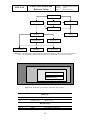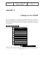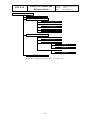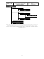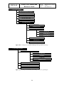
1
NWP SAF
Satellite Application Facility for Numerical Weather Prediction
Document NWPSAF-KN-UD-006
Version 1.0.01
December 2011
OWDP User Manual and Reference Guide
Anton Verhoef, Jur Vogelzang, Jeroen Verspeek and Ad Stoffelen
KNMI, De Bilt, the Netherlands
OWDP User Manual and
Reference Guide
NWP SAF
Doc ID : NWPSAF-KN-UD-006
Version : 1.0.01
Date
: December 2011
OWDP User Manual and Reference Guide
KNMI, De Bilt, the Netherlands
This documentation was developed within the context of the EUMETSAT Satellite Application
Facility on Numerical Weather Prediction (NWP SAF), under the Cooperation Agreement dated
16 December, 2003, between EUMETSAT and the Met Office, UK, by one or more partners
within the NWP SAF. The partners in the NWP SAF are the Met Office, ECMWF, KNMI and
Météo France.
Copyright 2011, EUMETSAT, All Rights Reserved.
Change record
Version
Date
Author / changed by
Remarks
1.0
Dec 2011
Anton Verhoef
First draft
NWP SAF
OWDP User Manual and
Reference Guide
Doc ID : NWPSAF-KN-UD-006
Version : 1.0.01
Date
: December 2011
Contents
CONTENTS .................................................................................................................................................... 1
PREFACE ....................................................................................................................................................... 4
CHAPTER 1
1.1
1.2
1.3
1.4
1.5
AIMS AND SCOPE ............................................................................................................................ 5
DEVELOPMENT OF OWDP.............................................................................................................. 5
TESTING OWDP............................................................................................................................. 5
USER MANUAL AND REFERENCE GUIDE ........................................................................................ 6
CONVENTIONS ................................................................................................................................ 6
CHAPTER 2
2.1
2.2
2.3
2.3.1
2.3.2
2.3.3
2.3.4
2.3.5
2.3.6
2.3.7
2.4
2.5
2.6
2.7
OWDP USER MANUAL................................................................................................... 7
WHY USING THE OWDP PROGRAM? .............................................................................................. 7
MODES OF USING OWDP ............................................................................................................... 9
INSTALLING OWDP ..................................................................................................................... 10
Directories and files................................................................................................................ 11
Environment variables ............................................................................................................ 12
Installing the BUFR library .................................................................................................... 13
Installing the GRIB API library .............................................................................................. 13
Installing the HDF5 library .................................................................................................... 13
Compilation and linking ......................................................................................................... 14
Some remarks for Cygwin users ............................................................................................. 15
COMMAND LINE OPTIONS ............................................................................................................. 16
SCRIPTS ........................................................................................................................................ 18
TEST DATA AND TEST PROGRAMS ................................................................................................. 18
DOCUMENTATION......................................................................................................................... 20
CHAPTER 3
3.1
3.2
3.3
3.4
3.5
3.5.1
3.5.2
3.5.3
3.5.4
3.5.5
3.5.6
3.5.7
3.6
INTRODUCTION.............................................................................................................. 5
OWDP PRODUCT SPECIFICATION .......................................................................... 21
PURPOSE OF PROGRAM OWDP..................................................................................................... 21
OUTPUT SPECIFICATION ................................................................................................................ 21
INPUT SPECIFICATION ................................................................................................................... 21
SYSTEM REQUIREMENTS ............................................................................................................... 22
DETAILS OF FUNCTIONALITY ........................................................................................................ 22
BUFR IO and coding .............................................................................................................. 22
Backscatter slice averaging .................................................................................................... 23
Atmospheric attenuation ......................................................................................................... 24
Quality control........................................................................................................................ 24
Inversion ................................................................................................................................. 24
Ambiguity Removal ................................................................................................................. 25
Monitoring .............................................................................................................................. 25
DETAILS OF PERFORMANCE .......................................................................................................... 25
CHAPTER 4
PROGRAM DESIGN ...................................................................................................... 27
4.1
TOP LEVEL DESIGN ...................................................................................................................... 27
4.1.1
Main program ......................................................................................................................... 27
4.1.2
Layered model structure ......................................................................................................... 28
4.1.3
Data Structure......................................................................................................................... 29
4.1.4
Quality flagging and error handling....................................................................................... 30
4.1.5
Verbosity ................................................................................................................................. 30
4.2
MODULE DESIGN FOR GENSCAT LAYER ........................................................................................ 31
NWP SAF
OWDP User Manual and
Reference Guide
Doc ID : NWPSAF-KN-UD-006
Version : 1.0.01
Date
: December 2011
4.2.1
Module inversion .................................................................................................................... 31
4.2.2
Module ambrem ...................................................................................................................... 31
4.2.3
Module icemodel..................................................................................................................... 31
4.2.4
Module Bufrmod ..................................................................................................................... 31
4.2.5
Module gribio_module............................................................................................................ 32
4.2.6
Module HDF5Mod.................................................................................................................. 32
4.2.7
Support modules ..................................................................................................................... 32
4.3
MODULE DESIGN FOR PROCESS LAYER ......................................................................................... 33
4.3.1
Module owdp_data ................................................................................................................. 33
4.3.2
Module owdp_bufr.................................................................................................................. 39
4.3.3
Module owdp_hdf5 ................................................................................................................. 40
4.3.4
Module owdp_prepost............................................................................................................. 40
4.3.5
Module owdp_grib.................................................................................................................. 41
4.3.6
Module owdp_inversion.......................................................................................................... 42
4.3.7
Module owdp_ambrem............................................................................................................ 42
4.3.8
Module owdp_icemodel .......................................................................................................... 43
4.3.9
Module owdp .......................................................................................................................... 43
CHAPTER 5
5.1
5.2
5.3
BACKGROUND .............................................................................................................................. 44
ROUTINES ..................................................................................................................................... 45
ANTENNA DIRECTION ................................................................................................................... 46
CHAPTER 6
6.1
6.2
6.3
6.4
6.4.1
6.4.2
6.4.3
6.4.4
6.4.5
6.4.6
6.4.7
6.4.8
MODULE BUFRMOD..................................................................................................... 61
BACKGROUND .............................................................................................................................. 61
ROUTINES ..................................................................................................................................... 61
DATA STRUCTURES ...................................................................................................................... 63
LIBRARIES .................................................................................................................................... 64
BUFR TABLE ROUTINES ............................................................................................................... 65
CENTRE SPECIFIC MODULES.......................................................................................................... 65
CHAPTER 9
9.1
9.2
9.3
9.4
MODULE ICEMODELMOD .......................................................................................... 57
BACKGROUND .............................................................................................................................. 57
ROUTINES ..................................................................................................................................... 58
DATA STRUCTURES ...................................................................................................................... 58
PARAMETERS................................................................................................................................ 59
CHAPTER 8
8.1
8.2
8.3
8.4
8.5
8.6
AMBIGUITY REMOVAL MODULE ........................................................................... 47
AMBIGUITY REMOVAL ................................................................................................................. 47
MODULE AMBREM ......................................................................................................................... 47
MODULE BATCHMOD ................................................................................................................... 48
THE KNMI 2DVAR SCHEME ....................................................................................................... 51
Introduction ............................................................................................................................ 51
Data structure, interface and initialisation............................................................................. 51
Reformulation and transformation.......................................................................................... 54
Module CostFunction ............................................................................................................. 54
Adjoint method........................................................................................................................ 54
Structure Functions................................................................................................................. 55
Minimization ........................................................................................................................... 55
SingletonFFT_Module ............................................................................................................ 56
CHAPTER 7
7.1
7.2
7.3
7.4
INVERSION MODULE .................................................................................................. 44
MODULE GRIBIO_MODULE ....................................................................................... 66
BACKGROUND .............................................................................................................................. 66
ROUTINES ..................................................................................................................................... 66
DATA STRUCTURES ...................................................................................................................... 68
LIBRARIES .................................................................................................................................... 69
REFERENCES ............................................................................................................................................. 70
APPENDIX A
CALLING TREE FOR OWDP................................................................................. 72
2
NWP SAF
OWDP User Manual and
Reference Guide
Doc ID : NWPSAF-KN-UD-006
Version : 1.0.01
Date
: December 2011
APPENDIX B1
CALLING TREE FOR INVERSION ROUTINES................................................. 82
APPENDIX B2
CALLING TREE FOR AR ROUTINES.................................................................. 85
APPENDIX B3
CALLING TREE FOR BUFR ROUTINES ............................................................ 89
APPENDIX B4
CALLING TREE FOR GRIB ROUTINES ............................................................. 91
APPENDIX B5
CALLING TREE FOR HDF5 ROUTINES ............................................................. 93
APPENDIX B6
CALLING TREE FOR ICE MODEL ROUTINES ................................................ 96
APPENDIX C
BUFR DATA DESCRIPTORS ................................................................................. 97
APPENDIX D
ACRONYMS ............................................................................................................ 102
APPENDIX E
HDF5 LIBRARY COPYRIGHT STATEMENT................................................... 103
3
NWP SAF
OWDP User Manual and
Reference Guide
Doc ID : NWPSAF-KN-UD-006
Version : 1.0.01
Date
: December 2011
Preface
Software code for processing satellite data may become very complex. On the one hand, it consists
of code related to the technical details of the satellite and instruments; on the other hand, the code
drives complex algorithms to create the physical end products. Therefore, the EUMETSAT
Satellite Application Facility (SAF) project for Numerical Weather Prediction (NWP) has included
some explicit activities aiming at enhancing the modularity, readability and portability of the
processing code.
The Indian Oceansat-2 satellite carries a Ku-band rotating pencil beam scatterometer and was
launched in September 2009. Its configuration very much resembles the SeaWinds instrument and
the new OSCAT Wind Data Processor (OWDP) is heavily based on SDP. This document is the
corresponding reference manual. We hope this manual will strongly contribute to the
comprehension of future developers and of users interested in the details of the processing.
For several years, the KNMI observation research group has been developing processing code to
supply Near Real Time (NRT) level 2 surface wind products based on the ERS, SeaWinds and
ASCAT Scatterometer level 1b Normalized Radar Cross Section data (σ 0). This work is
coordinated and supervised by Ad Stoffelen. In the beginning only an adaptation of his ERS code
existed. Later Marcos Portabella and Julia Figa added modifications and extensions to improve,
e.g., the wind retrieval and quality control algorithms. In 2003, John de Vries finished the first
official release of a processor within the NWP SAF. This processor was called the QuikSCAT
Data Processor (QDP).
Meanwhile, Jos de Kloe has been updating the code for ERS scatterometer wind processing. For
many parts of the process steps (e.g., the BUFR handling and part of the wind retrieval) a large
overlap with SeaWinds Data processing coding exists. The KNMI Scatterometer Team is working
towards generic NRT scatterometer processing. As a result, a new modular processing code for
SeaWinds data was developed within the NWP SAF: the SeaWinds Data Processor (SDP) as
successor of QDP. Based on the generic code already available for SeaWinds and ERS processing,
a new ASCAT Wind Data Processor (AWDP) was developed.
Many persons contributed (directly or indirectly) to the development of the scatterometer software
at KNMI: Hans Bonekamp, Jos de Kloe, Marcos Portabella, Ad Stoffelen, Anton Verhoef, Jeroen
Verspeek, Jur Vogelzang and John de Vries are (in alphabetical order) the most important
contributors.
Anton Verhoef, November 2011
4
NWP SAF
OWDP User Manual and
Reference Guide
Doc ID : NWPSAF-KN-UD-006
Version : 1.0.01
Date
: December 2011
Chapter 1
Introduction
1.1
Aims and scope
The OSCAT Wind Data Processor (OWDP) is a software package written in Fortran 90 for
handling data from the Oceansat-2 scatterometer instrument (OSCAT). Details of this instrument
can be found in [Padia, 2010] and on several web sites, see, e.g., information on the ISRO web
site.
OWDP generates surface winds based on OSCAT radar backscatter data. It allows performing the
ambiguity removal with the Two-dimensional Variational Ambiguity Removal (2DVAR) method
and it supports the Multiple Solution Scheme (MSS). The output of OWDP consists of wind
vectors which represent surface winds within the ground swath of the scatterometer. Input of
OWDP is Normalized Radar Cross Section (NRCS, σ 0) data. These data may be near real-time.
The input files of OWDP are in BUFR or Hierarchical Data Format (HDF5). Output is written
using the SeaWinds BUFR template or the KNMI BUFR template with generic wind section.
Currently, the level 2a data from the Indian Space Research Organisation (ISRO) are only
available on 50 km grid spacing, but in principle it is possible to convert OSCAT level 1b data into
a 25 km level 2a product and process this on 25 km using OWDP.
Apart from the OSCAT input data, OWDP needs Numerical Weather Prediction (NWP) model
winds as a first guess for the Ambiguity Removal step. These data need to be provided in GRIB
edition 1 or 2.
1.2
Development of OWDP
OWDP is developed within the Numerical Weather Prediction Satellite Application Facility (NWP
SAF) and Ocean and Sea Ice Satellite Application Facility (OSI SAF) programs as code which can
be run in an operational setting. The coding is in Fortran 90 and has followed the procedures
specified for the NWP SAF. Special attention has been paid to robustness and readability. OWDP
may be run on every modern Unix or Linux machine. In principle, OWDP can also be run on a
Windows machine if a Unix emulator like Cygwin is installed.
1.3
Testing OWDP
Modules are tested by test programs and test routines. Many test routines or test support routines
5
NWP SAF
OWDP User Manual and
Reference Guide
Doc ID : NWPSAF-KN-UD-006
Version : 1.0.01
Date
: December 2011
are part of the modules themselves. Test programs can be compiled separately. For the OWDP
program, the description of the test programs and the results of the testing are reported in [Verhoef
et. al., 2011].
1.4
User Manual and Reference Guide
This document is intended as the complete reference book for OWDP.
Chapter 2 is the user manual (UM) for the OWDP program. This chapter provides the basic
information for installing, compiling, and running OWDP. Chapter 3 contains the Product
Specification (PS) of the OWDP program. Reading the UM and the PS should provide sufficient
information to the user who wants to apply the OWDP program as a black box.
The subsequent chapters are of interest to developers and users who need more specific
information on how the processing is done. The Top Level Design (TLD) of the code and the
Module Design (MD) of the OWDP code can be found in Chapter 4. Several modules are very
generic for NRT scatterometer data processing. Examples are the modules for the BUFR and
GRIB handling, ambiguity removal, and parts of the wind retrieval. These generic modules are
part of the generic scatterometer (genscat) layer and are described in Chapter 5 to Chapter 9.
The appendices of this document contain a complete calling tree of the OWDP program up to and
including the genscat layer. The appendices also contain a list of BUFR data descriptors and a list
of acronyms.
1.5
Conventions
Names of physical quantities (e.g., wind speed components u and v), modules (e.g. BufrMod),
subroutines and identifiers are printed italic.
Names of directories and subdirectories (e.g. owdp/src), files (e.g. owdp.F90), and
commands (e.g. owdp -f input) are printed in Courier. Software systems in general are
addressed using the normal font (e.g. OWDP, genscat).
Hyperlinks are printed in blue and underlined (e.g. http://www.knmi.nl/scatterometer/).
References are in square brackets with the name of the author italic (e.g. [Stoffelen, 1998]).
6
NWP SAF
OWDP User Manual and
Reference Guide
Doc ID : NWPSAF-KN-UD-006
Version : 1.0.01
Date
: December 2011
Chapter 2
OWDP User Manual
This chapter is the user manual of the OWDP program. Sections 2.1 and 2.2 give general
information about OWDP. Section 2.3 provides information on how to install, compile, and link
the OWDP software. The command line arguments of OWDP are discussed in section 2.4. Section
2.5 gives information on a script for running OWDP.
Please note that any questions or problems regarding the installation or use of OWDP can be
addressed at the NWP SAF helpdesk at http://www.nwpsaf.org/.
2.1
Why using the OWDP program?
Scatterometers provide valuable observational data over the world's oceans. Therefore, successful
assimilation of scatterometer data in numerical weather prediction systems generally improves
weather forecasts. The OWDP program has been developed to fully exploit scatterometer data. It
is meant to form the key component of the observation operator for surface winds in data
assimilation systems.
The general scheme of OWDP (and any other wind scatterometer data processor) is given in figure
2.1. The input of the OWDP program is the ISRO level 2a slice HDF5 backscatter product or the
OWDP BUFR wind product. The ISRO level 2b HDF5 wind data can also be read and written to
BUFR format. Besides OSCAT data, GRIB input containing land-sea mask, sea surface
temperature and first guess winds over the globe is necessary.
The OWDP processing chain contains several steps (see figure 2.1):
1. Pre-processing. The input file is decoded and the radar backscatter (σ 0) values are written in
the data structures of OWDP. The slice level backscatter data are averaged to a backscatter
value on Wind Vector Cell level. Some quality control on the input data is done.
2. Collocation with NWP data. The GRIB edition 1 or 2 files containing NWP data are read and
the values for land fraction, sea surface temperature and first guess winds are interpolated and
stored with the information of each WVC.
3. Inversion. The σ 0 values are compared to the Geophysical Model Function (GMF) by means
of a Maximum Likelihood Estimator (MLE). The wind vectors that give the best description of
the σ 0 values (the solutions) are retained. The MLE is also used to assign a probability to each
wind vector. The normal scheme allows 4 solutions at most, but in the Multiple Solution
7
NWP SAF
OWDP User Manual and
Reference Guide
Doc ID : NWPSAF-KN-UD-006
Version : 1.0.01
Date
: December 2011
Scheme (MSS) the maximum number of solutions is 144.
4. Quality Control. Solutions that lie far away from the GMF are likely to be contaminated by,
e.g., sea ice or confused sea state. During Quality Control these solutions are identified and
flagged.
5. Ambiguity Removal. This procedure identifies the most probable solution using some form of
external information. OWDP uses a two-dimensional variational scheme (2DVAR) as default.
A cost function is minimized that consists of a background wind field and all solutions with
their probability, using meteorological balance, mass conservation and continuity as
constraints.
6. Quality Monitoring. The last step is to output quality indicators to an ASCII monitoring file
and to write the results in a BUFR format output file.
Input
(σ 0 values)
Pre-processing
Input
(NWP data)
NWP collocation
Inversion
Quality Control
NWP
model
Ambiguity Removal
Quality Monitoring
Output wind
field
Figure 2.1 OWDP processing scheme. The wind vectors and their probabilities after Quality Control may
be fed directly in the Data Assimilation step of a Numerical Weather Prediction model.
Steps 2 and 6 of the processing chain are rather trivial; the real work is done in steps 1, 3, 4, and 5.
As further detailed in Chapter 3, OWDP profits from developments in
• Inversion and output of the full probability density function of the vector wind (Multiple
Solution Scheme, MSS) [Stoffelen and Portabella, 2006; Portabella and Stoffelen, 2004].
•
Quality Control (QC) [Portabella and Stoffelen, 2001, Portabella, 2002].
•
Meteorologically balanced Ambiguity Removal (2DVAR) [Vogelzang et al., 2009].
•
Quality monitoring.
•
Capability to process OSCAT data on both 50 km and 25 km cell spacing.
A complete specification of the OWDP program can be found in the Product Specification in
8
NWP SAF
OWDP User Manual and
Reference Guide
Doc ID : NWPSAF-KN-UD-006
Version : 1.0.01
Date
: December 2011
Chapter 3. The program is based on generic genscat routines for inversion, ambiguity removal, and
BUFR and GRIB file handling. These routines are discussed in more detail in Chapter 5 to Chapter
9.
Figure 2.2 OWDP wind field of hurricane Katia retrieved in the western Atlantic at 50 km WVC spacing
on 7 September 2011, approximately 4:15 UTC, overlaid on a GOES IR satellite image. The orange dots are
rejected WVCs, the purple dots indicate WVCs for which the land flag is set. The two orange arrows near
the hurricane centre failed the 2DVAR spatial consistency check.
2.2
Modes of using OWDP
There are several modes to assimilate the OSCAT data in NWP models using OWDP. Anyway,
the first thing to assure oneself of is the absence of biases by making scatter plots between OSCAT
and NWP model first guess for at least wind speed, but wind direction and wind components
would also be of interest to guarantee consistency; for more detailed guidance on bias correction
see [Vogelzang and Stoffelen, 2011].
9
NWP SAF
OWDP User Manual and
Reference Guide
Doc ID : NWPSAF-KN-UD-006
Version : 1.0.01
Date
: December 2011
The OSCAT wind product, available as a deliverable from the EUMETSAT OSI SAF project,
could be the starting point for NWP data assimilation:
1. The unique solution at every WVC may be assimilated as if it were buoy data. This is the
fastest way and one exploits the data to a large extent. For a small advantage, OWDP could be
installed to provide 2DVAR solutions based on the local first guess.
2. The OWDP software may be used to modify the 3DVAR or 4DVAR data assimilation system
to work with the ambiguous wind solutions and their probabilities at every WVC in order to
provide the full information content to the data assimilation system. This represents some
investment, but the approach is generic and applicable to all scatterometer data. With respect
to option 1, this option only occasionally leads to an improved ambiguity removal, but often in
dynamical atmospheric cases (storms or cyclones) that are really relevant.
Both options can be based on OWDP in standard or MSS mode [Stoffelen and Portabella, 2004].
MSS is somewhat more dependent on the balance constraints in 2DVAR or your own data
assimilation system than the standard OWDP, but much less noisy. A substantial advantage is thus
obtained by using option 2 and MSS, where potentially the full benefit of the OSCAT data is
achieved. The mode of using OWDP thus depends on the opportunities, experience, and time the
user has to experiment with OSCAT data in the NWP system under consideration; for more
detailed guidance on scatterometer data assimilation see [Vogelzang and Stoffelen, 2011].
The OWDP program can, of course, also be used to create a stand-alone wind product, e.g., for
nowcasting purposes. Such a stand-alone OSCAT wind product is a deliverable of the OSI SAF
project. More information on this project can be found on http://www.osi-saf.org/.
2.3
Installing OWDP
OWDP is written in Fortran 90 (with a few low level modules in C) and is designed to run on a
modern computer system under Linux or Unix. OWDP needs a Fortran 90 compiler and a C
compiler for installation. OWDP comes along with a complete make system for compilation. In
some cases, the Makefiles call installation scripts which are written in Bourne shell to enhance
portability. When compiled, OWDP requires about 150-200 Mb disk space.
In principle, OWDP may also run under Windows. However, it needs the BUFR and GRIB API
libraries from ECMWF, and this poses some restrictions on the systems supported. Under
Windows one must use a (free) Unix emulator like Cygwin (see http://www.cygwin.com/ for more
information and download, and section 2.3.7 for some directions).
To install OWDP, the following steps must be taken:
1. Copy the OWDP package (file OWDP<version>.tar.gz) to the directory from which
OWDP will be applied, and unzip and untar it. This will create subdirectories owdp and
genscat that contain all code needed (see section 2.3.1), and a script called InstallOWDP
for easy compilation.
2. Download the ECMWF BUFR library file bufr_000387.tar.gz (or another version not
earlier than 000240) and copy it to directory genscat/support/bufr. See also section
2.3.3.
10
NWP SAF
OWDP User Manual and
Reference Guide
Doc ID : NWPSAF-KN-UD-006
Version : 1.0.01
Date
: December 2011
3. Download the ECMWF GRIB API library file grib_api-1.9.9.tar.gz (or another
version not earlier than 1.9.0) and copy it to directory genscat/support/grib. See also
section 2.3.4.
4. Go to the top directory and run the ./InstallOWDP script. The script will ask for the
compiler used and it will invoke the make system for compilation and linking of the software
(see also section 2.3.6).
OWDP is now ready for use, provided that the environment variables discussed in section 2.3.2
have the proper settings. See also sections 2.4 and 2.5 for directions on how to run OWDP.
2.3.1
Directories and files
All code for OWDP is stored in a file named OWDP<version>.tar.gz that is made available
in the framework of the NWP SAF project. This file should be placed in the directory from which
OWDP is to be run. After unzipping (with gunzip OWDP<version>.tar.gz) and untarring
(with tar -xf OWDP<version>.tar), the OWDP package is extracted in subdirectories
owdp and genscat, which are located in the directory where the tar file was located.
Subdirectories owdp and genscat each contain a number of files and subdirectories. A copy of
the release notes can also be found in the directory owdp/docs.
Tables 2.1 and 2.2 list the contents of directories owdp and genscat, respectively, together with
the main contents of the various parts. Depending on the distribution, more directories may be
present, but these are of less importance to the user.
Name
doc
execs
src
test
Contents
Documentation, including this document
Link to owdp executable, shell script for running OWDP
Source code for OWDP program and supporting routines
Example BUFR and GRIB input files for testing purposes.
Table 2.1 Contents of directory owdp.
Name
ambrem
ambrem/twodvar
icemodel
inversion
main
support
support/BFGS
support/bufr
support/Compiler_Features
support/convert
support/datetime
support/ErrorHandler
support/file
support/grib
support/hdf5
support/num
Contents
Ambiguity removal routines
KNMI 2DVAR ambiguity removal routines
Ice screening routines
Inversion and quality control routines
Dummy subdirectory to facilitate the make system
General purpose routines sorted in subdirectories
Minimization routines needed in 2DVAR
BUFR tables (in subdirectory) and file handling routines
Compiler specific routines, mainly command line handling
Conversion between wind speed/direction and u and v
Date and time conversion routines
Error handling routines
File handling routines
GRIB file handling routines
HDF5 handling routines
Numerical definitions and number handling routines
11
NWP SAF
OWDP User Manual and
Reference Guide
Name
support/singletonfft
support/sort
Doc ID : NWPSAF-KN-UD-006
Version : 1.0.01
Date
: December 2011
Contents
FFT routines needed in minimization
Sorting routines
Table 2.2 Contents of directory genscat.
Directories owdp and genscat and their subdirectories contain various file types:
•
Fortran 90 source code, recognizable by the .F90 extension;
•
C source code, recognizable by the .c extension;
•
Files and scripts that are part of the make system for compilation like Makefile_thisdir,
Makefile, use_, and Set_Makeoptions (see 2.3.4 for more details);
•
Scripts for the execution of OWDP in directory owdp/execs;
•
Look-up tables and BUFR tables needed by OWDP;
•
Files with information like Readme.txt.
After compilation, the subdirectories with the source code will also contain the object codes of the
various modules and routines.
2.3.2
Environment variables
OWDP needs a number of environment variables to be set. These are listed in table 2.3 together
with their possible values.
Name
$BUFR_TABLES
$GRIB_DEFINITION_PATH
$LUT_FILENAME_KU_HH
$LUT_FILENAME_KU_VV
$LUTSDIR
Value
genscat/support/bufr/bufr_tables/
genscat/support/grib/definitions
owdp/data/<platform>/nscat2_250_73_51_hh.dat
owdp/data/<platform>/nscat2_250_73_51_vv.dat
owdp/data
Table 2.3 Environment variables for OWDP.
The $BUFR_TABLES variable guides OWDP to the BUFR tables needed to read the input and
write the output. The $GRIB_DEFINITION_PATH variable is necessary for a proper functioning
of the GRIB decoding software.
The variables $LUT_FILENAME_KU_HH and $LUT_FILENAME_KU_VV point OWDP to the
correct binary Ku band GMF lookup tables at HH and VV polarisation, respectively. They should
contain a file name including a valid path. NSCAT lookup tables are delivered with OWDP in big
endian and little endian binary formats, the <platform> part in the paths should be set to
big_endian or little_endian depending on your computer platform type.
The variable $LUTSDIR points OWDP to a directory containing some look up tables that are used
to normalise the inversion residuals and to compute atmospheric attenuations for the Ku band
radar data. The necessary tables are delivered with OWDP.
12
NWP SAF
2.3.3
OWDP User Manual and
Reference Guide
Doc ID : NWPSAF-KN-UD-006
Version : 1.0.01
Date
: December 2011
Installing the BUFR library
OWDP needs the ECMWF BUFR library for its input and output operations. Only ECMWF is
allowed to distribute this software. It can be obtained free of charge from ECMWF at the web page
http://www.ecmwf.int/products/data/software/bufr.html. The package contains scripts for
compilation and installation. The reader is referred to this site for assistance in downloading and
installing the BUFR Library.
Directory genscat/support/bufr contains the shell script make.bufr.lib. It unzips,
untars, and compiles the BUFR library file which is downloaded from ECMWF and placed into
this directory. This script is part of the genscat make system and it is automatically invoked when
compiling genscat. The current version is tested with BUFR version 000387, but later versions (or
earlier, but not earlier than 000240) can be used. However, OWDP is not tested with later versions.
BUFR file handling at the lowest level is difficult to achieve. Therefore some routines were coded
in C. These routines are collected in library bufrio (see also section 8.4). Its source code is located
in file bufrio.c in subdirectory genscat/support/bufr. Compilation is done within the
genscat make system and requires no further action from the user (see 2.3.6).
2.3.4
Installing the GRIB API library
OWDP needs the ECMWF GRIB API library for its input operations. Only ECMWF is allowed to
distribute this software. It can be obtained free of charge from ECMWF at the web page
http://www.ecmwf.int/products/data/software/grib_api.html. The package contains scripts for
compilation and installation. The reader is referred to this site for assistance in downloading and
installing the GRIB API Library.
Directory genscat/support/grib contains the shell script make.grib.lib. It unzips,
untars, and compiles the GRIB API library file which is downloaded from ECMWF and placed
into this directory. This script is part of the genscat make system and it is automatically invoked
when compiling genscat. The current version is tested with GRIB API version 1.9.9, but later
versions (or earlier, but not earlier than 1.9.0) can be used. However, OWDP is not tested with
later versions.
2.3.5
Installing the HDF5 library
The HDF5 software library from the HDF Group (http://www.hdfgroup.org/) is used by OWDP
for reading and decoding HDF5 input files. See Appendix E for the copyright statement and the
terms of use of this software. Binary libraries, compiled for different Linux and Unix platforms are
delivered with OWDP in directory genscat/support/hdf5/hdfgroup. The Makefile in
this directory tries to determine the operating system and creates a symbolic link from one of the
binary
libraries
to
a
file
called
libhdf5.a.
For
example,
directory
genscat/support/hdf5/hdfgroup contains a library called libhdf5_lin_i386.a
which is compiled for the 32 bits Linux platform. The Makefile will link this file to
libhdf5.a, which in its turn will be linked when compiling OWDP. The same mechanism is
used for some of the include files (.h) in this directory, which are also platform specific. This
directory also contains the binary SZIP and ZLIB libraries that are used in conjunction with the
HDF5 library.
13
OWDP User Manual and
Reference Guide
NWP SAF
Doc ID : NWPSAF-KN-UD-006
Version : 1.0.01
Date
: December 2011
Note that the collection of delivered libraries is by no means complete and it may be necessary for
some platforms to download specific versions of the HDF5 software libraries from
http://www.hdfgroup.org/
and
to
place
them
under
the
correct
name
in
genscat/support/hdf5/hdfgroup. See the file Readme.txt in this directory for more
information.
2.3.6
Compilation and linking
Compilation and linking of OWDP under Linux or Unix is done in three steps:
1. Set the compiler environment variables according to the choice entered on request. This can be
done by running the appropriate use_* scripts in directory genscat.
2. Go to directory genscat and type make.
3. Go to directory owdp and type make to produce the executable owdp in directory
owdp/src.
Before activating the make system, some environment variables identifying the compiler should be
set. These variables are listed in table 2.4. The environment variables in table 2.4 can be set by
using one of the use_* scripts located in directory genscat. Table 2.5 shows the properties of
these scripts. The scripts are available in Bourne shell (extension .bsh) and in C shell (extension
.csh). Note that if one of the environment variables is not set, the default f90 and cc commands
on the Unix platform will be invoked. Note that in the top directory a script called InstallOWDP
is provided that asks the user which compiler he wants to use and invokes the appropriate use_*
script (step 1 above), after which the compilation in the genscat and owdp directories is
performed (steps 2 and 3 above).
Variable
$GENSCAT_F77
$GENSCAT_F90
$GENSCAT_CC
$GENSCAT_LINK
$GENSCAT_CLINK
$GENSCAT_SHLINK
Function
Reference to Fortran 77 compiler
Reference to Fortran 90 compiler
Reference to C compiler
Reference to linker for Fortran objects
Reference to linker for C objects
Reference to linker for shared objects
Table 2.4 Environment variables for compilation and linking.
Script
use_g95
use_gfortran
use_ifort
use_pgf90
Fortran
compiler
g95
gfortran
ifort
pgf90
C
compiler
gcc
gcc
icc
gcc
Remarks
GNU compilers by Andy Vaught
GNU-GCC compiler collection
Intel Fortran and C compilers
Portland Fortran compiler
Table 2.5 Properties of the use_* scripts.
Example: To select the GNU g95 compiler under Bourne, Bash or Korn shell type
“. use_g95.bsh”, the dot being absolutely necessary in order to apply the compiler selection
14
NWP SAF
OWDP User Manual and
Reference Guide
Doc ID : NWPSAF-KN-UD-006
Version : 1.0.01
Date
: December 2011
to the current shell. Under C shell the equivalent command reads “source use_g95.csh”.
If the user wants to use a Fortran or C compiler not included in table 2.6, he can make his own
version of the use_* script, or set the environment variables for compilation and linking
manually.
OWDP is delivered with a complete make system for compilation and linking under Unix or
Linux. The make system is designed as portable as possible, and system dependent features are
avoided. As a consequence, some tasks must be transferred to shell scripts. The make system
consists of two parts: one for OWDP and one for genscat. The genscat part should be run first. For
compilation and linking of the genscat part, the user should move to the genscat directory and
simply enter make.
The Makefile refers to each subdirectory of genscat, invoking execution of the local
Makefile and, in cases where a subdirectory contains code as well as a subdirectory containing
code, Makefile_thisdir. The settings for the compilers are located in file Makeoptions in
directory genscat. This file is generated by the Bourne shell script Set_Makeoptions
which is called automatically by the genscat make system. The local Makefile in subdirectory
genscat/support/bufr calls the script make.bufr.lib for compilation of the BUFR
library (see 2.3.3). It also contains the Fortran program test_modules that generates the binary
BUFR tables B and D from the ASCII tables already present, and is executed automatically by the
make system. Program test_modules can also be used to test the genscat BUFR module. The
Makefile in subdirectory genscat/support/bufr/bufr_tables calls some shell
scripts, which make symbolic links (using the ln -s command) of the generic BUFR tables B
and D under different names. There are four different naming conventions in BUFR version
000240 to 000280, and binary files are generated for each of them. Symbolic links are not
guaranteed to work on each platform (e.g. by some versions of Cygwin under Windows XP), so in
some cases it may be necessary to replace the ln -s by cp (copy). Further information on the
make system is given in the inline comments in the scripts and Makefiles.
Compilation and linking of the OWDP part is done in a similar manner: go to the owdp directory
and enter make. As with genscat, the make system will execute Makefiles in every subdirectory of
owdp. The result is the executable owdp in directory owdp/src and a symbolic link to this
executable in owdp/execs. OWDP is now ready for use. The make system of OWDP doesn’t
need any further files except the genscat file Makeoptions. This is the reason why genscat
should be compiled first.
When recompiling (part of) OWDP or genscat with the make system, for instance when installing
a new version of the BUFR library, one should be sure to enter make clean first. To recompile
part of the software invoke the make system where needed. The compiler settings from file
Makeoptions in directory genscat will be used again. If a change in these settings is
necessary, type make clean in the genscat directory and Makeoptions will be removed.
Don’t forget to rerun the use_* commands to select the right compiler.
2.3.7
Some remarks for Cygwin users
OWDP can be used under Cygwin, a Unix emulator running under Windows. Installing and
running OWDP under Cygwin is almost the same as under Unix or Linux, but the following points
15
NWP SAF
OWDP User Manual and
Reference Guide
Doc ID : NWPSAF-KN-UD-006
Version : 1.0.01
Date
: December 2011
may be helpful for Cygwin users.
•
The GNU g95 compiler comes standard with Cygwin (version 1.5.25-11 and later) so it is
always possible to install OWDP using g95.
•
Cygwin has its own path naming convention, for example: C:\owdp under Windows
becomes /cygdrive/c/owdp under Cygwin.
•
Don’t forget to run the dos2unix command on scripts edited under Windows, otherwise
Cygwin won’t recognize the file as a script!
2.4
Command line options
The OWDP program is started from directory owdp/execs with the command
owdp [options/modes] -f <HDF5/BUFR file> [-nwpfl <file>]
with <> indicating obligatory input, and [] indicating non-obligatory input. The following
command line options are available.
-f <input file> Process an HDF5 or BUFR input file with name input file.
OWDP detects if the input file is in BUFR format. If not, it attempts to
read the input as HDF5 file. The input file should contain 50 or 25 km
level 2a or level 2b data.
Example: owdp -f S1L2A2011311_11243_11244_2.h5 will
process this file. The results will be written to a new BUFR file, see below
in this section for the output file naming convention. It is possible to
concatenate multiple BUFR input files into one using the Unix cat
command, but HDF5 files must be processed one by one.
-nwpfl <file>
Read a list of GRIB file names in the file named file.
The files in the list are read and the GRIB edition 1 or 2 data are used in
the wind processing. The most convenient way to construct a file list is to
use the Unix command ls -1 GRIB file pattern > file. If no
GRIB data are used, only the land masking which is present in the
level 2a/b files will be used. No ice screening will be performed (unless
the -icemodel option is used). Ambiguity removal will be performed
only if model winds are already present in the input BUFR file (i.e., in
case of reprocessing of a level 2 file) or if the -armeth 1strank
option is used (i.e., selection of the 1st rank wind solution). If level 2 data
are reprocessed and no NWP data are read, the qual_sigma0 flag
which was set in the initial processing is evaluated and it will be used to
determine if a WVC contains suitable backscatter data for wind inversion.
Several options for the processing can be invoked.
-noinv
Switch off inversion (default is switched on).
-icemodel
Switch on ice screening.
When switched off, no ice screening is done, except when a GRIB file
containing sea surface temperature is read. The command line option
16
NWP SAF
OWDP User Manual and
Reference Guide
Doc ID : NWPSAF-KN-UD-006
Version : 1.0.01
Date
: December 2011
invokes the Bayesian ice model which keeps the history of each location
and uses this history to determine the sea or ice state of a WVC.
-noamb
Switch off ambiguity removal (default is switched on).
This option is useful if the selection of the scatterometer wind solution is
left to the data assimilation procedure of a Numerical Weather Prediction
model. In other words: the NWP model is fed with a number of solutions
and their probability, and finds the best value when comparing with other
data sources.
-nowrite
Do not produce BUFR output (default is switched on).
-calval
Perform σ 0 calibration.
A calibration of the σ 0. values is performed, i.e., the backscatter values are
changed by a WVC dependent value in order to obtain better calibrated
winds. See [TBD] for more details.
-mss
Use the Multiple Solution Scheme for Ambiguity Removal.
If the Multiple Solution Scheme (MSS) is switched on, OWDP internally
works with 144 different solutions for the wind vector. If MSS is switched
off, OWDP calculates two solutions at most. MSS is switched off as
default.
-armeth <meth>
Choose ambiguity removal method.
Valid methods are: 1strank - the wind solution with the lowest distance
to the GMF (residual) is selected, bgclosest - the wind solution closest
to the background model wind is selected, 2dvar - 2DVAR, see section
6.4. The default is 2dvar.
-genericws <N>
This option generates a second BUFR output file in the KNMI generic
wind section format not yet approved by the WMO.
The number of wind solutions to be written into the KNMI BUFR format
is flexible due to the use of the so-called delayed replication and can be
chosen between 1 (providing only the selected wind solution) and 144
(providing all wind solutions in MSS processing).
-binof <file>
Write selected data of each WVC to a binary output file.
Data are written to a binary file <file>. This option is intended for
research activities. More information on the file format can be found in the
Fortran code of OWDP.
-mon
Switch on the monitoring function.
The monitoring results are written in an ASCII file with the name <name
of BUFR output file>.txt. By default, no monitoring file is
produced.
-verbosity <L>
Set the verbosity level to L (default is 0).
If the verbosity level is -1 or smaller, no output is written to the standard
output except error messages. If the verbosity level equals 0 only some top
level processing information is written to output. If the verbosity level is 1
17
NWP SAF
OWDP User Manual and
Reference Guide
Doc ID : NWPSAF-KN-UD-006
Version : 1.0.01
Date
: December 2011
or greater, also additional information is given.
The normal mode of operation of OWDP is wind processing, i.e., a HDF5 or BUFR file is read
and the various processing steps are performed.
Besides the wind processing, some other modes of operation are available. If one of the modes is
invoked, OWDP internally sets some of the options in order to obtain the desired result. Note that
these modes are always used in combination with the -f <input file> option.
-mononly
Write the monitoring file without any processing.
-properties
Write some properties of the last row of the input file.
The acquisition date and time are written to a small ASCII output file
properties.txt.
-writeonly
Write all data to BUFR output without processing.
This mode is useful to copy an input file to BUFR output without
processing.
Running the command owdp without any command line options will display a list of all available
command line options with a short explanation on the console. Running the command owdp with
an illegal option will produce the same output, but preceded by an error message.
The output will be written into a BUFR file with a name which is derived from the input file name.
•
If the input file name contains the substring L2A, this part will be replaced by L2B.
•
If the input file name contains the substring .h5, this part will be replaced by .bufr.
•
The extension .bufr is added to the output file name when it is not yet present.
•
If the above substitutions result in identical input and output file names, the extension ‘~’ is
added to the output file name.
Example: the input file name S1L2A2011311_11243_11244_2.h5 results in an output file
name S1L2B2011311_11243_11244_2.bufr.
2.5
Scripts
Directory owdp/execs contains a Bourne shell script owdp_run for running owdp with the
correct environment variables. The script can be invoked with all valid command line options for
owdp.
2.6
Test data and test programs
Directory owdp/tests contains one HDF5 file for testing the OWDP executable. File
S1L2A2011311_11243_11244_2.h5.gz contains (gzipped) OSCAT level 2a data from 7
November 2011, 13:51 to 14:03 UTC with 50 km cell spacing, as obtained from ISRO. The files
ECMWF*.grib contain the necessary NWP data (SST, land-sea mask and wind forecasts) to
perform the NWP collocation step.
The user can test the proper functioning of OWDP using the files in the owdp/tests directory.
To do this, first create a small file containing a list of NWP files:
18
NWP SAF
OWDP User Manual and
Reference Guide
Doc ID : NWPSAF-KN-UD-006
Version : 1.0.01
Date
: December 2011
ls -1 ECMWF_* > nwpflist
Then, gunzip the HDF5 file:
gunzip -c S1L2A2011311_11243_11244_2.h5.gz >
S1L2A2011311_11243_11244_2.h5
Then run OWDP:
../execs/owdp_run -f S1L2A2011311_11243_11244_2.h5 -nwpfl nwpflist
-mss -mon -calval
The result should be an OSCAT level 2 file in BUFR format, called
S1L2B2011311_11243_11244_2.bufr.
Figure 2.3 shows the global coverage of the test run. The colours indicate the magnitude of the
wind speed as indicated by the legend.
Figure 2.3 Global coverage of the test run. Wind speed results for the 50 km product are shown.
Directory genscat/support/bufr contains a test program named test_modules. It is
invoked by the genscat make system to construct the BUFR tables required by OWDP, but it can
also be used to test the genscat BUFR module. The program is used as follows:
test_modules [BUFRinput]
where BUFRinput is the BUFR input file.
If omitted, the program uses as default input the file testreading.bufr in directory
genscat/support/bufr. The output is written to a BUFR file named
testwriting.bufr. The directory also contains a shell script named run_test_modules
that sets the environment variables required and executes the program. Further information can be
found in the comment lines of the source code of test_modules.
Directory genscat/support/grib contains test programs named test_read_GRIB1,
test_read_GRIB2 and test_read_GRIB3. The programs can be run from the command
line and read in the GRIB file testfile.grib in directory genscat/support/grib.
19
NWP SAF
OWDP User Manual and
Reference Guide
Doc ID : NWPSAF-KN-UD-006
Version : 1.0.01
Date
: December 2011
Some properties of this file are written to ASCII output files. Note that the environment variable
$GRIB_DEFINITION_PATH
needs
to
be
set
to
directory
(…)/genscat/support/grib/definitions.
Subdirectories Compiler_Features, convert, ErrorHandler, singletonfft, file,
BFGS, num, hdf5, sort and datetime of genscat/support contain test programs for the
module in that subdirectory. The test programs write their result to the standard output. In some
cases, a copy of the output is contained in the .output files for comparison. Table 2.6 gives an
overview of the genscat test programs.
Subdirectory
bufr
grib
Compiler_Features
convert
ErrorHandler
singletonfft
file
BFGS
num
hdf5
sort
datetime
Program name
test_modules
test_read_GRIB*
TestCompiler_Features
test_convert
TestErrorHandler
TestSingleton
TestLunManager
Test_BFGS
test_numerics
TestHDF5
SortModTest
TestDateTimeMod
Output file
testwriting.bufr
several
test_convert.output
TestLunManager.output
test_numerics.output
SortModTest.output
TestDateTimeMod.output
Remarks
Part of make system
GRIB handling
Command line handling
Wind speed conversion
Error handling
Fast Fourier Transform
File management
Minimization
Numerical issues
Read HDF5 file
Array sorting
Date and time conversion
Table 2.6 Test programs in genscat/support.
2.7
Documentation
Directory owdp/doc contains documentation on OWDP, including this document. Further
information can be found in the readme text files, and in the comments in scripts, Makefiles and
source code.
20
NWP SAF
OWDP User Manual and
Reference Guide
Doc ID : NWPSAF-KN-UD-006
Version : 1.0.01
Date
: December 2011
Chapter 3
OWDP product specification
3.1
Purpose of program OWDP
The OSCAT Wind Data Processor (OWDP) program has been developed to fully exploit σ 0 data
from the scatterometer instrument on the Oceansat-2 satellite, to generate surface winds. OWDP
may be used for real-time data processing. The main application of OWDP is to form the core of
an Observation Operator for OSCAT scatterometer data within an operational Numerical Weather
Prediction System.
Program OWDP is also a level 2 data processor. It reads data from the ISRO level 2a OSCAT
HDF5 product or from the OSCAT scatterometer BUFR product generated by OWDP itself.
OWDP applies algorithms for inversion, quality control, and Ambiguity Removal. These methods
are mainly developed and published by KNMI. The output of OWDP is a BUFR file in the NOAA
BUFR format that was used for QuikSCAT data [Leidner et. al., 2000]. Additionally, a BUFR file
containing a generic wind section (identical to the wind part of the ASCAT BUFR files) can be
written. This BUFR format (also referred to as KNMI BUFR format) is not yet approved by
WMO.
3.2
Output specification
The wind vectors generated by OWDP represent the instantaneous mean surface wind at 10 m
anemometer height in a 2D array of Wind Vector Cells (WVCs) with specified size (50 × 50 km2
or 25 × 25 km2, depending on the cell spacing of the input product). These WVCs are part of the
ground swath of the instrument.
In conventional mode, the wind output for every WVC consists of up to 4 ambiguities (wind
vector alternatives, with varying probabilities). The selected wind vector is indicated by a selection
index. For every WVC additional parameters are stored. These are e.g.: latitude, longitude, time
information, orbit and node numbers, NWP background wind vector, WVC quality flag, and
information on the scatterometer beams including σ 0 and Kp data.
The BUFR data descriptors of both available data formats are listed in Appendix C.
3.3
Input specification
Input of OWDP is the OSCAT level 2a (L2A) HDF5 Data Product. These products are created by
21
NWP SAF
OWDP User Manual and
Reference Guide
Doc ID : NWPSAF-KN-UD-006
Version : 1.0.01
Date
: December 2011
ISRO; see [Padia, 2010]. The first operational ISRO L2A product is denoted version 1.3. OWDP
has the ability to process earlier experimental and pre-operational versions as well. Alternatively,
the OSCAT level 2b HDF5 Wind Data Product can be read, but in this case wind processing is not
possible since the level 2b product does not contain σ 0 data.
It is also possible to reprocess level 2 OSCAT in NOAA BUFR format or KNMI BUFR format
containing generic wind section, and treat them as if they are input data.
Apart from the scatterometer data, GRIB files containing NWP output with global coverage are
necessary for the wind processing. At least three wind forecasts with forecast time intervals of 3
hours are necessary to perform interpolation with respect to time and location. Apart from this,
GRIB fields of Sea Surface Temperature and Land Sea Mask are necessary for land and ice
masking.
3.4
System requirements
Table 3.1 shows the platform and compiler combinations for which OWDP has been tested.
However, the program is designed to run on any Unix (Linux) based computer platform with a
Fortran compiler and a C compiler. The equivalent of a modern personal computer will suffice to
provide a timely NRT wind product. OWDP requires about 150-200 MB disk space when installed
and compiled.
Platform
Suse workstation or
Fedora workstation
SunOS Unix
SGI Altix
Fortran compiler
Portland pgf90
GNU g95
GNU gfortran
Sun Fortran
Intel Fortran compiler
C compiler
GNU gcc
Sun C
Intel C compiler
Table 3.1 Platform and compiler combinations for which OWDP has been tested.
OWDP may also run in other environments, provided that the environment variables discussed in
section 2.2 are set to the proper values, and that the BUFR and GRIB libraries are properly
installed. For Windows a Unix emulator like Cygwin is needed.
3.5
Details of functionality
3.5.1
BUFR IO and coding
Data sets of near-real time meteorological observations are generally coded in the Binary
Universal Form for Representation (BUFR). BUFR is a machine independent data representation
system (but it contains binary data, so care must be taken in reading and writing these data under
different operating systems). A BUFR message (record) contains observational data of any sort in
a self-descriptive manner. The description includes the parameter identification and its unit,
decimal, and scaling specifications. The actual data are in binary code. The meta data are stored in
BUFR tables. These tables are therefore essential to decode and encode the data.
BUFR tables are issued by the various meteorological centres. The largest part of the data
22
OWDP User Manual and
Reference Guide
NWP SAF
Doc ID : NWPSAF-KN-UD-006
Version : 1.0.01
Date
: December 2011
descriptors specified in the BUFR tables follows the official BUFR descriptor standards
maintained by the World Meteorological Organization (WMO, http://www.wmo.int/). However,
for their different observational products meteorological centres do locally introduce additional
descriptors in their BUFR tables.
Appendix C contains a listing of the data descriptors of the BUFR data output of the OWDP
program in the NOAA QuikSCAT BUFR product format and the KNMI BUFR format with
generic wind section. For more details on BUFR, the reader is referred to [Dragosavac, 1994].
ECMWF maintains a library of routines for reading (writing) and decoding (encoding) the binary
BUFR messages. This library forms the basis of the genscat BUFR module and hence the OWDP
program BUFR interface, see Chapter 8.
3.5.2
Backscatter slice averaging
The HDF5 level 2a backscatter data from ISRO are organised in slices, see [Padia, 2010]. The
slices need to be beamwise accumulated to a Wind Vector Cell (WVC) level before wind inversion
can be done. The individual slice contributions are averaged using:
σ =
0
∑α
−1
S
σ S0
S
∑α
(3.1)
−1
S
S
where σ 0 is the WVC backscatter, σ 0S is the slice backscatter and αS is the slice Kp-alpha. The
weights αS-1 were found to be proportional to the estimated transmitted power contained in a slice
and thus the above weighting relates to a summation over backscattered power. The Sigma0
Quality Flag present in the HDF5 data is evaluated and slice data with one of the following flags
set are skipped:
•
σ 0 is poor
•
Kp is poor
•
Invalid footprint
•
Footprint contains saturated slice
The WVC Kp values α, β and γ are computed from the slice Kp’s as
−1
⎛
−1 ⎞
α = ⎜ ∑ αS ⎟ ,
⎝ S
⎠
−1
−1
⎛
⎛
−1 ⎞
−1 ⎞
β = ⎜ ∑ βS ⎟ , γ = ⎜ ∑ γS ⎟ ,
⎝ S
⎠
⎝ S
⎠
(3.2)
the WVC received power P is computed from the slice received power as
P = ∑ PS , PS = 2 ⋅ SNR S / β S
(3.3)
S
and the WVC SNR is calculated as
23
NWP SAF
OWDP User Manual and
Reference Guide
SNR = β ⋅ P 2 .
Doc ID : NWPSAF-KN-UD-006
Version : 1.0.01
Date
: December 2011
(3.4)
Now Kp2 = α + β/SNR + γ/SNR2 is obtained for each WVC view.
3.5.3
Atmospheric attenuation
The Ku band radiation from OSCAT is attenuated by the atmosphere. Climatological values of this
attenuation were determined as a function of location and time of the year [Wentz, 1996]. The
attenuation is based on a climatology of water vapour. The attenuation includes atmospheric
oxygen, water vapour, and nominal cloud. A mean global cloud cover of 0.1 mm is assumed.
A table containing the monthly climatological attenuations was kindly provided by NOAA and it
is delivered with OWDP in data/atm_attn_360_180_12.dat. The attenuations are the
same that were used for QuikSCAT. The one-way nadir looking values Amap (dB) in the table are
transformed into an attenuation correction A using the following formula:
A = 2 Amap / cos(θ ) ,
(3.5)
where θ is the beam incidence angle, and the attenuation correction is added to the beam σ 0 value
(in dB). The two-way nadir looking values (i.e., without the incidence angle correction) are stored
in the BUFR output data.
3.5.4
Quality control
The quality of every WVC is controlled. Before processing the beam data, checks are done on the
completeness and usability of the σ 0 data. After the wind inversion step, the distance of the wind
solutions to the GMF (also known as Maximum Likelihood Estimator, MLE) is considered. If this
value is too large, the wind solutions are flagged. The MLE threshold depends on WVC number
and wind speed. The optimum threshold values are determined using the same method as was used
for QuikSCAT in the past [Portabella, 2002].
3.5.5
Inversion
In the inversion step of wind retrieval, the radar backscatter observations in terms of the
Normalized Radar Cross Sections (σ 0’s) are converted into a set of ambiguous wind vector
solutions. In fact, a Geophysical Model Function (GMF) is used to map a wind vector (specified in
term of wind speed and wind direction) to a σ 0 value. The GMF depends not only on wind speed
and wind direction but also on the measurement geometry (relative azimuth and incidence angle)
and beam parameters (frequency and polarization). The NSCAT2 GMF is delivered with OWDP;
it is the same GMF that also proved to be successful in the SDP processing software for
QuikSCAT.
The OWDP program also includes the Multiple Solution Scheme (MSS). In MSS mode, a large
number of wind vector solutions is produced, typically 144. The wind vector solutions are ranked
according to their probability based on the MLE and constitute the full wind vector probability
density function. Subsequently, the 2DVAR Ambiguity Removal method, see, e.g., section 3.5.6,
is applied with a much larger set of wind vector solutions. The output BUFR format can
24
OWDP User Manual and
Reference Guide
NWP SAF
Doc ID : NWPSAF-KN-UD-006
Version : 1.0.01
Date
: December 2011
accommodate any number of wind solutions due to the use of the so-called delayed descriptor
replication. Details on the KNMI inversion approach can be found in [Stoffelen and Portabella,
2006]. For SeaWinds, MSS compares better to an independent NWP model reference and buoys
than conventional two or four-solution schemes [Portabella and Stoffelen, 2004; Vogelzang et al.,
2009], and for OSCAT the same can be expected.
Technical information on the KNMI inversion approach can be found in Chapter 5.
3.5.6
Ambiguity Removal
The Ambiguity Removal (AR) step of the wind retrieval is the selection of the most probable
surface wind vector among the available wind vector solutions, the so-called ambiguities. Various
methods have been developed for AR. More information on Ambiguity Removal is given in
Chapter 6. The default method implemented in OWDP is the KNMI 2DVAR AR scheme. A
description of its implementation can be found in section 6.4. The Multiple Solution Scheme
(MSS) offers the possibility to postpone AR to the NWP data assimilation step in order to use the
full information content of the scatterometer measurements. Further details on the algorithms and
their validation can be found in the reports [de Vries and Stoffelen, 2000; de Vries, Stoffelen and
Beysens, 2005].
The performance of 2DVAR with meteorological balance constraints was tested and optimized for
ERS data. It was found to be superior to other schemes. Further testing for SeaWinds is described
in [Vogelzang et. al., 2009].
3.5.7
Monitoring
For the automatic ingestion of observations into their NWP systems, meteorological centres
require quality checks on the NRT products. For the OSCAT wind product a monitoring flag is
under development, analogous to the one developed for the SeaWinds Wind Product. This flag
indicates that several measures on the level of corruption of the output BUFR files are above a
specified threshold. Onset of the flag indicates that the input should be rejected for ingestion in the
NWP data assimilation system. Details on the monitoring flag can be found in the NWP SAF
document [de Vries, Stoffelen and Beysens, 2005].
3.6
Details of performance
Table 3.2 gives the approximate times needed for processing one level 2a 50 km orbit file under
various options on a workstation with a 3.00 GHz Intel Core(TM)2 Duo CPU processor under
Linux using the Portland Fortran compiler.
Cell spacing (m)
MSS?
50000
50000
No
Yes
Inversion
(seconds)
11.5
13
AR
(seconds)
1
4
BUFR IO
(seconds)
0.4
0.4
GRIB IO
(seconds)
0.5
0.5
Total
(seconds)
15
19
Table 3.2 Approximate times needed by OWDP to process example HDF5 files using various options.
As can be seen from table 3.2, the use of MSS results in slightly larger processing times needed for
25
NWP SAF
OWDP User Manual and
Reference Guide
Doc ID : NWPSAF-KN-UD-006
Version : 1.0.01
Date
: December 2011
inversion, in much larger processing times needed for AR and a modest overall increase in
processing time (~25%).
The choice of platform, compiler and compiler settings will generate a large variation in the
processing times.
26
NWP SAF
OWDP User Manual and
Reference Guide
Doc ID : NWPSAF-KN-UD-006
Version : 1.0.01
Date
: December 2011
Chapter 4
Program Design
In this chapter, the design of the OWDP program is described in detail. Readers to whom only a
summary will suffice are referred to the Top Level Design (TLD) in section 4.1. Readers who
really want to know the very detail should not only read the complete chapter, but also the
documentation within the code.
4.1
Top Level Design
4.1.1
Main program
The main program, OWDP, (file owdp in the owdp/src directory) is a Unix (Linux) executable
which processes OSCAT HDF5 or BUFR input files. The main output consists of BUFR files. The
output BUFR messages are in the NOAA BUFR format or in the KNMI BUFR format with
generic wind section, for a list of descriptors see appendix C. The user may provide arguments and
parameters according to Unix command line standards. The purpose of the different options is
described in the User Manual (Chapter 2).
When executed, the OWDP program logs information on the standard output. The detail of this
information may be set with the verbosity flag. The baseline of processing is described in Figure
4.1, but note that not all of these steps are always invoked. Some of them will be skipped,
depending on the command line options. A more detailed representation of the OWDP structure is
given in Appendices A and B.
The first step is to process the arguments given at the command line using the genscat
Compiler_Features module. Next, the OWDP program reads the input file specified in the
arguments. The BUFR messages or HDF5 data are read and mapped onto the OWDP data
structure, see subsection 4.1.3. As part of the pre-processing some checks on the input data are
done, the atmospheric attenuations are computed and σ 0 calibration is performed when applicable.
Then, the NWP GRIB data (wind forecasts, land-sea mask and sea surface temperature) are read
and the data are collocated with the Wind Vector Cells. The next steps are the inversion and the
ambiguity removal. The program ends with the post-processing step (which includes some
conversions and the monitoring) and the mapping of the output data structure onto BUFR
messages of the BUFR output file. The different stages in the processing correspond directly to
specific modules of the code. These modules form the process layer, see section 4.3.
27
NWP SAF
OWDP User Manual and
Reference Guide
Doc ID : NWPSAF-KN-UD-006
Version : 1.0.01
Date
: December 2011
Process arguments
Read input data
Pre-processing
Read/collocate GRIB data
Inversion
Ice screening
Ambiguity Removal
Post-processing
Write output BUFR message
Figure 4.1 Baseline of the OSCAT Wind Data Processor
4.1.2
Layered model structure
OWDP is a Fortran 90 program consisting of several Fortran 90 modules which are linked after
their individual compilation. The OWPD program is set up from two layers of software modules.
The purpose of the layer structure is to divide the code into generic scatterometer processing
software and OSCAT specific software. Details on the individual modules can be found in sections
4.2 and 4.3.
The first layer (the process layer) consists of modules which serve the main steps of the process.
Module name
owdp_data
owdp_bufr
owdp_hdf5
owdp_prepost
owdp_grib
owdp_inversion
Τasks
Definition of data structures
BUFR file handling
HDF5 file handling
Quality control
Atmospheric attenuation
Backscatter calibration
Post processing
Monitoring
Clean up
GRIB file handling
Collocation of GRIB data
Inversion
Comments
Interface to genscat/support/bufr
Interface to genscat/support/hdf5
Usability of input data is determined
Setting of flags
Deallocation of used memory
Interface to genscat/support/grib
NWP data are interpolated w.r.t. time and location
Interface to genscat/inversion
28
OWDP User Manual and
Reference Guide
NWP SAF
Module name
owdp_ambrem
owdp_icemodel
Τasks
Ambiguity Removal
Ice screening
Doc ID : NWPSAF-KN-UD-006
Version : 1.0.01
Date
: December 2011
Comments
Interface to genscat/ambrem
Interface to genscat/icemodel
Table 4.1 OWDP process modules.
Each module contains code for performing one or more of the specific tasks. These tasks are
briefly described in table 4.1. A more elaborate description is given in section 4.3. The first
module listed, owdp_data is a general support module. This module is used by the other modules
of the process layer for the inclusion of definitions of the data structures and the support routines.
The second module layer is the genscat layer. The genscat module classes (i.e., groups of modules)
used in the OWDP program are listed in table 4.2. The genscat package is a set of generic modules
which can be used to assemble processors as well as pre, and post-processing tools for different
scatterometer instruments available to the user community. A short description of the main
(interface) modules is given in section 4.2. The most important classes of modules are related to
the inversion processing step (Chapter 5), the Ambiguity Removal step (Chapter 6), the BUFR file
handling (Chapter 8), and the GRIB file handling (Chapter 9). The genscat modules are located in
subdirectory genscat.
In addition, genscat contains a large support class to convert and transform meteorological,
geographical, and time data, to handle file access and error messages, sorting, and to perform more
complex numerical calculations on minimization and Fourier transformation. Many routines are
co-developed for ERS, ASCAT and SeaWinds data processing.
Module class
Ambrem
Inversion
IceModel
Support
Tasks
Ambiguity Removal
Wind retrieval
Ice screening
BUFR support
HDF5 support
GRIB support
FFT, minimization
Error handling
File handling
Conversion
Sorting
Date and time
Description
2DVAR and other schemes, see Chapter 6
Inversion in one cell, see Chapter 5
Uses ice line and wind cone for ice discremination
BufrMod, based on ECMWF library
Reading of HDF5 files
gribio_module, based on ECMWF library
Support for 2DVAR
Print error messages
Finding, opening and closing free file units
Conversion of meteorological quantities
Sorting of ambiguities to their probability
General purpose
Table 4.2 genscat module classes.
4.1.3
Data Structure
Along track, the OSCAT swath is divided into rows. Within a row (across track), the OSCAT orbit
is divided into cells, also called Wind Vector Cells (WVCs) or nodes. This division in rows and
cells forms the basis of the main data structures within the OWDP package. In fact, both the input
and the output structure are one dimensional arrays of the row data structure, row_type. These
arrays represent just a part of the swath. Reading and writing (decoding and encoding) OSCAT
data files corresponds to the mapping of a BUFR message or HDF5 datasets to one or more
29
NWP SAF
OWDP User Manual and
Reference Guide
Doc ID : NWPSAF-KN-UD-006
Version : 1.0.01
Date
: December 2011
instances of the row_type and vice versa.
The main constituent of the row_type is the cell data structure, cell_type, see figure 4.2. Since most
of the processing is done on a cell-by-cell basis the cell_type is the pivot data structure of the
processor.
row_type
cell_type
beam_type
ambiguity_type
Figure 4.2 Schematic representation of the nested data definitions in the row_type data structure.
The σ 0 related level 1b data of a cell are stored in a data structure called beam_type. Every cell
contains four instances of the beam_type, corresponding to the inner fore, outer fore, inner aft, and
outer aft beams.
A cell may also contain an array of instances of the ambiguity_type data structure. This array
stores the results of a successful wind retrieval step, the wind ambiguities (level 2 data). Details of
all the data structures and methods working on them are described in the next sections.
4.1.4
Quality flagging and error handling
Important aspects of the data processing are to check the validity of the data and to check the data
quality. In the OWDP program two flags are set for every WVC, see table 4.3. The flags
themselves do not address a single aspect of the data, but the flags are composed of several bits
each addressing a specific aspect of the data. A bit is set to 0 (1) in case the data is valid (not valid)
with respect to the corresponding aspect. In order to enhance the readability of the code, each flag
is translated to a data type consisting of only booleans (false = valid, true = invalid). On input and
output these data types are converted to integer values by set and get routines.
Flag
wvc_quality
process_flag
Tasks
Quality checking
Range checking
Description
In BUFR output
Not in BUFR output
Table 4.3 Flags for every WVC (attributes of cell_type).
Apart from the flags on WVC level, also the beams contain quality indicators. See section 4.3.1 for
more information on this.
4.1.5
Verbosity
Every routine in a module may produce some data and statements for the log of the processor. To
30
NWP SAF
OWDP User Manual and
Reference Guide
Doc ID : NWPSAF-KN-UD-006
Version : 1.0.01
Date
: December 2011
control the size the log, several modules contain parameters for the level of verbosity. The
verbosity of the OWDP program may be controlled by the verbosity command line option
-verbosity. In general, there are three levels of verbosity specified:
≤ -1:
be as quiet as possible;
0:
only report top level processing information;
≥ 1:
report additional information.
Of course, errors are logged in any case. Table 4.4 gives a (incomplete) list of verbosity
parameters. They are not all set by the command line option as some of them serve testing and
debugging purposes.
Module
Ambrem2Dvar
AmbremBGclosest
BatchMod
Ambrem
owdp_bufr
owdp_hdf5
owdp_grib
Verbosity parameter
TDVverbosity
BGverbosity
BatchVerbosity
AmbremVerbosity
BufrVerbosity
hdf5_verbosity
GribVerbosity
Table 4.4 Verbosity parameters.
4.2
Module design for genscat layer
4.2.1
Module inversion
The module inversion contains the genscat inversion code. Module post_inversion contains some
routines for probability computations. The modules are located in subdirectory
genscat/inversion. Details of this module are described in Chapter 5. In the OWDP
program, the inversion module is only used in the owdp_inversion module, see section 4.3.6.
4.2.2
Module ambrem
The module ambrem is the main module of the genscat Ambiguity Removal code. It is located in
subdirectory genscat/ambrem. Details of this module are described in Chapter 6. In the
OWDP program, the ambrem module is only used in the owdp_ambrem module, see section 4.3.7.
4.2.3
Module icemodel
The module icemodel contains the genscat ice screening code. It is located in subdirectory
genscat/icemodel. In the OWDP program, the icemodel module is only used in the
owdp_icemodel module, see section 4.3.8.
4.2.4
Module Bufrmod
Genscat contains several support modules. In particular, the BufrMod module is the Fortran 90
wrapper around the BUFR library used for BUFR input and output. It is located in subdirectory
31
NWP SAF
OWDP User Manual and
Reference Guide
Doc ID : NWPSAF-KN-UD-006
Version : 1.0.01
Date
: December 2011
genscat/support/bufr. Details of this module are described in Chapter 8. In the OWDP
program, the BufrMod module is only used in the owdp_bufr module, see subsection 4.3.2.
4.2.5
Module gribio_module
The gribio_module module is the Fortran 90 wrapper around the GRIB API library used for GRIB
input and collocation of the NWP data with the scatterometer data. It is located in subdirectory
genscat/support/grib. Details of this module are described in Chapter 9. In the OWDP
program, the gribio_module module is used in the owdp_grib module, see subsection 4.3.5.
4.2.6
Module HDF5Mod
The HDF5Mod module is the Fortran 90 wrapper around the HDF5 library from the HDF Group,
used for HDF5 input. It is located in subdirectory genscat/support/hdf5. In the OWDP
program, the HDF5Mod module is only used in the owdp_hdf5 module, see subsection 4.3.3.
4.2.7
Support modules
Subdirectory genscat/support contains more support modules besides Bufrmod,
gribio_module and HDF5Mod. The KNMI 2DVAR Ambiguity Removal method requires
minimization of a cost function and numerical Fourier transformation. These routines are located
in subdirectories BFGS and singletonfft, respectively, and are discussed in more detail in
section 6.4.
Subdirectory Compiler_Features contains module Compiler_Features for handling some
compiler specific issues, mainly with respect to command line argument handling. The
Makefile in this directory compiles on of the available source files, depending on the Fortran
compiler used.
Subdirectory convert contains module convert for the conversion of meteorological and
geographical quantities, e.g. the conversion of wind speed and direction into u and v components
and vice versa.
Subdirectory datetime contains module DateTimeMod for date and time conversions. OWDP
only uses routines GetElapsedSystemTime (for calculating the running time of the various
processing steps), and DayJulian and ymd2julian (for conversion between Julian day number and
day, month and year). Module DateTimeMod needs modules ErrorHandler and numerics.
Subdirectory ErrorHandler contains module ErrorHandler for error management. This
module is needed by module DateTimeMod.
Subdirectory file contains module LunManager for finding, opening and closing free logical
units in Fortran. OWDP uses only routines get_lun and free_lun for opening and closing of a
logical unit, respectively.
Subdirectory num contains module numerics for handling missing values, for instance in the
BUFR library. This module is needed by module DateTimeMod and is used in the test program
test_modules.
Subdirectory sort, finally, contains module SortMod for sorting the wind vector solutions
according to their probability. This module is needed by modules inversion and post_inversion.
32
OWDP User Manual and
Reference Guide
NWP SAF
4.3
Doc ID : NWPSAF-KN-UD-006
Version : 1.0.01
Date
: December 2011
Module design for process layer
The process layer consists of the modules owdp_data, owdp_bufr, owdp_hdf5, owdp_prepost,
owdp_grib, owdp_inversion, owdp_icemodel and owdp_ambrem. The routines present in these
modules are described in the next sections.
4.3.1
Module owdp_data
The module owdp_data contains all the important data types relevant for the processing.
Elementary data types are introduced for the most basic data structures of the processing. These
are e.g. wind_type and time_type. Using these data types (and of course the standard types as
integer, real etc.), more complex (composed) data types are derived. Examples are beam_type,
ambiguity_type, cell_type, and row_type. A complete description of all types is given below. The
attributes of all these types have intentionally self-documenting names.
Ambiguity data: The ambiguity_type data type contains information on an individual ambiguity
(wind vector solution). The attributes are listed in table 4.5. The routine init_ambiguity() sets all
ambiguity data to missing. The routine print_ambiguity() may be used to print all ambiguity data.
Attribute
wind
error_speed
error_dir
prob
conedistance
Type
wind_type
real
real
real
real
Description
Wind vector solution
Uncertainty in wind speed, not used in OWDP
Uncertainty in wind direction, not used in OWDP
Probability of wind vector solution
Distance of solution to the GMF
Table 4.5 Ambiguity data structure.
Beam data: Every WVC contains four beams. The information of every beam is stored in the data
type beam_type. The attributes are listed in table 4.6. The routine init_beam() sets all beam data to
missing and the routine test_beam checks if the data in the beam are within valid ranges. The
routine print_beam() may be used to print all beam data.
Attribute
sum_weights
num
identifier
k_polar
lat
lon
atten_val
azimuth
incidence
sigma0
snr
kp_a
kp_b
kp_c
s0_variance_qc
s0_quality
Type
real
integer
integer
integer
real
real
real
real
real
real
real
real
real
real
real
s0_quality_type
Description
Sum of weights, used in averaging of level 2a slices
Presence of backscatter data, 0 or 1
1 = inner fore, 2 = outer fore, 3 = inner aft, 4 = outer aft
Beam polarisation, 0 = HH pol, 1 = VV pol
Beam latitude
Beam longitude
Two-way nadir atmospheric attenuation
Radar look angle (degrees, counted clockwise from the North)
Incidence angle (degrees, 0 is vertical, 90 is horizontal)
Radar backscatter (σ 0) in dB
Signal to noise ratio
Noise value Kp α as fraction of 1
Noise value Kp β as fraction of 1
Noise value Kp γ in dB
σ 0 variance quality control, not used in OWDP
Flag related to the quality of the backscatter information
33
NWP SAF
Attribute
s0_mode
s0_surface
OWDP User Manual and
Reference Guide
Type
s0_mode_type
s0_surface_type
Doc ID : NWPSAF-KN-UD-006
Version : 1.0.01
Date
: December 2011
Description
Information about beam type
Information about land or ice presence
Table 4.6 Beam data structure.
Brightness temperature data: The btemp_type data type contains information on brightness
temperatures. Every WVC contains two brightness temperatures, for the vertically and horizontally
polarized beams. The attributes are listed in table 4.7. The routine init_btemp() sets all brightness
temperature data to missing.
Attribute
k_polar
tot_num
bright_temp
bright_temp_sd
Type
integer
integer
real
real
Description
Beam polarisation, 0 = HH pol, 1 = VV pol
Number of slices used in averaging
Brightness temperature in K
Standard deviation of brightness temperature
Table 4.7 Brightness temperature data structure..
Cell Data: The cell_type data type is a key data type in the OWDP program, because many
processing steps are done on a cell by cell basis. The attributes are listed in table 4.8. The routine
init_cell() sets the cell data to missing values. Also the flags are set to missing. The routine
test_cell() tests the validity of data. This routine sets the cell process flag. The routine print_cell()
may be used to print the cell data.
Attribute
centre_id
sub_centre_id
software_id_l1b
satellite_id
sat_instruments
sat_instr_short
gmf_id
sat_motion
time
lat
lon
time_to_edge
time_diff_qual
pixel_size_hor
orbit_nr
row_nr
node_nr
s0_in_cell
rain_prob
rain_nof
rain_rate
rain_attenuation
btemp (2)
beam (4)
software_id_wind
Type
integer
integer
integer
integer
integer
integer
integer
real
time_type
real
real
integer
integer
real
integer
integer
integer
integer
real
real
real
real
btemp_type
beam_type
integer
Description
Identification of originating/generating centre
Identification of originating/generating sub-centre
Software identification of level 1 processor
Satellite identifier
Satellite instrument identifier
Instrument short name, code table 02048
Identifier of GMF used, code table 21119
Direction of motion of satellite
Date and time of data acquisition
Latitude of WVC
Longitude of WVC
Time to beginning or end of data file (s)
Time difference qualifier, code table 08025
Distance between WVCs (meters)
Orbit number
Along track row number
Across track cell number
Number of beams containing data in cell
Probability of rain, not used in OWDP
Rain normalised objective function, not used in OWDP
Rain rate, not used in OWDP
Attenuation due to rain, not used in OWDP
Brightness temperature data
Beam data
Software identification of level 2 wind processor
34
NWP SAF
Attribute
generating_app
model_wind
ice_prob
ice_age
wvc_quality
num_ambigs
num_ambigs_n
selection
ambig (0..144)
ice
stress_param
process_flag
OWDP User Manual and
Reference Guide
Type
integer
wind_type
real
real
wvc_quality_type
integer
integer
integer
ambiguity_type
icemodel_type
nwp_stress_param_type
process_flag_type
Doc ID : NWPSAF-KN-UD-006
Version : 1.0.01
Date
: December 2011
Description
Generating application of model information
Model wind used for Ambiguity Removal
Probability of ice
Ice age A-parameter
WVC quality flag
Number of ambiguities present in WVC
Number of non-MSS ambiguities
Index of selected wind vector
Array of wind ambiguities
Ice information
Wind stress information
Processing flag
Table 4.8 Cell data structure.
Ice model data: The icemodel_type contains information related to the ice screening. The
attributes are listed in table 4.9. The routine init_icemodel() sets the ice model data to missing
values. The routine print_icemodel() may be used to print the ice data.
Attribute
class
ii
jj
b
c
dIce
Type
integer
integer
integer
real
real
real
Description
Code for WVC being ice or wind
Coordinate on the ice map
Coordinate on the ice map
Ice coordinate
Ice coordinate
Distance to the ice line
Table 4.9 Ice model data structure.
NWP stress parameter data: The nwp_stress_param_type data type contains information
relevant for the ice screening and wind stress calculations (stress calculation is not yet
implemented in OWDP). The attributes are listed in table 4.10. The routine
init_nwp_stress_param() sets the NWP stress parameter data to missing values. The routine
print_nwp_stress_param () may be used to print the stress data.
Attribute
u
v
t
q
sst
chnk
sp
Type
real
real
real
real
real
real
real
Description
Eastward (zonal) wind component
Northward (meridional) wind component
Air temperature
Specific humidity
Sea surface temperature
Charnok parameter
Surface pressure
Table 4.10 NWP stress parameter data structure.
Row data: The data of a complete row of the swath is stored in the data type row_type, see table
4.11. A complete row corresponds to a single BUFR message in the OWDP output.
35
OWDP User Manual and
Reference Guide
NWP SAF
Attribute
num_cells
Cell(76)
Type
integer
cell_type
Doc ID : NWPSAF-KN-UD-006
Version : 1.0.01
Date
: December 2011
Description
Actual number of WVC’s in this row
Array of Wind Vector Cells
Table 4.11 Row data structure.
Time data: The time_type data type contains a set of 6 integers representing both the date and the
time, see table 4.12. The routine init_time() sets the time entries to missing values. The routine
test_time() tests the validity of the date and time specification (see also the cell process flag). The
routine print_time() can be used to print the time information.
Attribute
year
month
day
hour
minute
second
Type
integer
integer
integer
integer
integer
integer
Description
19XX or 20XX
1 – 12
1 – 31
0 – 23
0 – 59
0 – 59
Table 4.12 Time data structure.
Wind Data: The wind_type data type contains the wind speed and wind direction, see table 4.13.
The routine init_wind() sets the wind vector to missing. The routine print_wind() may be used to
print the wind vector. The routine test_wind() tests the validity of the wind specification, see also
the cell process flag.
Attribute
speed
dir
Type
real
real
Description
Wind speed
Wind direction
Table 4.13 Wind data structure.
Some special data types are introduced for the data (quality) flags. These are discussed below.
Sigma0 quality flag: The s0_quality_type data type contains the flag indicating the quality of the
σ 0. Each of the four beams in a WVC contains an instance of this flag. The attributes are listed in
table 4.14. The function get_s0_quality() converts an integer value to the logical flag structure.
The function set_s0_quality() converts a logical flag structure to an integer value. Note that only a
few bits of this flag are used in OWDP.
Attribute
missing
usability
noise_ratio
negative
range
pulse
Bit
2Bit
15
14
13
12
11
32768
16384
8192
4096
2048
Description
Flag not set (all bits on)
σ 0 measurement not usable
Low signal to noise ratio
σ 0 is negative
σ 0 is outside acceptable range
Pulse quality not acceptable
36
OWDP User Manual and
Reference Guide
NWP SAF
Attribute
convergence
freq_shift
temperature
attitude
ephemeris
Bit
10
9
8
7
6
2Bit
1024
512
256
128
64
Doc ID : NWPSAF-KN-UD-006
Version : 1.0.01
Date
: December 2011
Description
Location algorithm does not converge
Frequency shift beyond range
Spacecraft temperature beyond range
No applicable attitude records
Interpolated ephemeris data
Table 4.14 Sigma0 quality flag bits (Fortran).
Sigma0 mode flag: The s0_mode_type data type contains the flag indicating the properties of the
σ 0 measurement. Each of the four beams in a WVC contains an instance of this flag. The attributes
are listed in table 4.15. The function get_s0_mode() converts an integer value (BUFR input) to the
logical flag structure. The function set_s0_mode() converts a logical flag to an integer value.
Attribute
missing
outer
aft
Bit
2Bit
13
12
8192
4096
Description
Flag not set (all bits on)
σ 0 is of outer beam
σ 0 is aft of satellite
Table 4.15 Sigma0 mode flag bits (Fortran).
Sigma0 surface flag: The s0_surface_type data type contains the flag indicating land or ice
presence in the σ 0 measurement. Each of the four beams in a WVC contains an instance of this
flag. The attributes are listed in table 4.16. The function get_s0_surface() converts an integer value
(BUFR input) to the logical flag structure. The function set_s0_surface() converts a logical flag to
an integer value.
Attribute
missing
land
ice
ice_map
atten_map
Bit
2Bit
15
14
5
4
32768
16384
32
16
Description
Flag not set (all bits on)
Land is present
Ice is present
Ice map data not available
Attenuation map data not available
Table 4.16 Sigma0 surface flag bits (Fortran)..
Wind Vector Cell quality flag: Every WVC contains a flag for its quality. Therefore the cell_type
contains an instance of the wvc_quality_type. Table 4.17 gives an overview of its attributes. The
implementation of this flag is different in the NOAA BUFR format and the KNMI BUFR format
with generic wind section. The functions get_wvc_quality_noaa() and get_wvc_quality_gen()
interpret an integer flag (BUFR input) to an instance of wvc_quality_type. The functions
get_wvc_quality_noaa() and get_wvc_quality_gen() transform an instance of wvc_quality_type to
an integer flag. The routine print_wvc_quality() may be used to print the bit values of the flag.
Attribute
missing
qual_sigma0
Bit
NOAA
2Bit
NOAA
Bit
KNMI
2Bit
KNMI
15
32768
22
4194304
37
Description
Flag not set (all bits on)
Not enough good σ 0 available for wind
OWDP User Manual and
Reference Guide
NWP SAF
Attribute
Bit
NOAA
2Bit
NOAA
Bit
KNMI
2Bit
KNMI
azimuth
kp
monflag
monvalue
knmi_qc
var_qc
land
ice
inversion
large
small
14
16384
12
11
10
9
8
7
6
5
4
4096
2048
1024
512
256
128
64
32
16
21
20
19
18
17
16
15
14
13
12
11
2097152
1048576
524288
262144
131072
65536
32768
16384
8192
4096
2048
3
2
8
4
1
13
2
8192
10
9
8
7
6
5
4
1024
512
256
128
64
32
16
rain_fail
rain_detect
no_background
redundant
gmf_distance
four beam
reserved
Doc ID : NWPSAF-KN-UD-006
Version : 1.0.01
Date
: December 2011
Description
retrieval
Poor azimuth diversity among σ 0
Any beam noise content above threshold
Product monitoring not used
Product monitoring flag
KNMI quality control fails
Variational quality control fails
Some portion of wind vector cell is over land
Some portion of wind vector cell is over ice
Wind inversion not successful
Reported wind speed is greater than 30 m/s
Reported wind speed is less than or equal to 3
m/s
Rain flag not calculated
Rain detected
No meteorological background used
Data are redundant
Distance to GMF too large
One of the four beams is missing
Reserved
Table 4.17 Wind Vector Cell quality flag bits (Fortran).
Cell process flag: Besides a cell quality flag, every WVC contains a process flag. The process flag
checks on aspects that are important for a proper processing, but are not available as a check in the
cell quality flag. The cell process flag is set by the routine test_cell, which calls routines test_time,
test_beam and test_wind.
Table 4.18 lists the attributes of the process_flag_type. The process flag is only available internally
in OWDP. The routine print_process_flag() may be used to print the bit values of the flag.
Attribute
satellite_id
sat_instruments
sat_motion
time
latlon
pixel_size_hor
node_nr
beam (4)
model_wind
ambiguity
selection
Description
Invalid satellite id
Invalid satellite instrument id
Invalid satellite direction of motion
Invalid date or time specification
Invalid latitude or longitude
Invalid cell spacing
Invalid across track cell number
Invalid data in one of the beams
Invalid background wind
Invalid ambiguities
Invalid wind selection
Table 4.18 Cell process flag bits (Fortran).
Table 4.19 provides an overview of all routines and their calls in module owdp_data.
Routine
copy_cell
Call
Description
Copy all information from one cell into another
38
NWP SAF
Routine
get_s0_mode
get_s0_quality
get_s0_surface
get_wvc_quality_gen
get_wvc_quality_noaa
init_ambiguity
init_beam
init_cell
init_icemodel
init_nwp_stress_param
init_process_flag
init_time
init_wind
print_ambiguity
print_beam
print_cell
print_icemodel
print_nwp_stress_param
print_process_flag
print_s0_mode
print_s0_quality
print_s0_surface
print_time
print_wind
print_wvc_quality
set_s0_mode
set_s0_quality
set_s0_surface
set_wvc_quality_gen
set_wvc_quality_noaa
test_beam
test_cell
test_time
test_wind
OWDP User Manual and
Reference Guide
Call
init_beam
init_beam
init_beam
init_cell
init_cell
init_cell
init_cell
init_cell
init_cell
init_cell
test_cell
test_cell
test_cell
Doc ID : NWPSAF-KN-UD-006
Version : 1.0.01
Date
: December 2011
Description
Convert integer σ 0 mode flag to logical structure
Convert integer σ 0 quality flag to logical structure
Convert integer σ 0 surface flag to logical structure
Convert integer WVC quality (generic) to logical structure
Convert integer WVC quality (KNMI) to logical structure
Initialise ambiguity structure
Initialise beam structure
Initialise cell structure
Initialise ice model structure
Initialise NWP stress parameters structure
Initialise process flag structure
Initialise time structure
Initialise wind structure
Print ambiguity structure
Print beam structure
Print cell structure
Print ice model structure
Print NWP stress parameters structure
Print process flag structure
Print σ 0 mode flag structure
Print σ 0 quality flag structure
Print σ 0 surface flag structure
Print time structure
Print wind structure
Print quality flag structure
Convert logical σ 0 mode flag to integer
Convert logical σ 0 quality flag to integer
Convert logical σ 0 surface flag to integer
Convert logical WVC quality to integer (generic)
Convert logical WVC quality to integer (NOAA)
Test validity of beam data
Test validity of cell data
Test validity of time data
Test validity of wind data
Table 4.19 Routines in module owdp_data
4.3.2
Module owdp_bufr
The module owdp_bufr maps the OWDP data structure on BUFR messages and vice versa. A list
of the BUFR data descriptors can be found in appendix C. The owdp_bufr module uses the genscat
module BufrMod, see subsection 4.2.4 for the interface with the BUFR routine library.
Table 4.20 provides an overview of the different routines and their calls in this module.
Routine
bufr_to_row_data_gen
bufr_to_row_data_noaa
init_bufr_processing
read_bufr_file
row_to_bufr_data_gen
row_to_bufr_data_noaa
Call
read_bufr_file
read_bufr_file
read_bufr_file,
write_bufr_file
OWDP
write_bufr_file
write_bufr_file
Description
KNMI format BUFR message into one row_type
NOAA format BUFR message into one row_type
Initialise module
Read a complete BUFR file into row_types
OWDP row_type into KNMI format BUFR message
OWDP row_type into NOAA format BUFR message
39
OWDP User Manual and
Reference Guide
NWP SAF
Routine
write_bufr_file
Call
OWDP
Doc ID : NWPSAF-KN-UD-006
Version : 1.0.01
Date
: December 2011
Description
Write all row_types into a complete BUFR file
Table 4.20 Routines in module owdp_bufr
Note that the OSCAT BUFR messages always contain exactly one data row.
4.3.3
Module owdp_hdf5
The module owdp_hdf5 maps the datasets in a HDF5 file on the OWDP data structure. It is
capable to read both level 2a and level 2b files from ISRO. For level 2a, only the backscatter
information in the OWDP data structure will be filled, for level 2b, only the wind information in
the OWDP data structure will be filled.
Table 4.21 provides an overview of the different routines and their calls in this module. Several
routines from the HDF5Mod module in genscat are called from this module to handle the HDF5
data. Appendix B5 shows the calling trees of the routines in module HDF5Mod that are used in
OWDP.
Routine
get_l2a_data
get_l2b_data
read_hdf5_file
Call
read_hdf5_file
read_hdf5_file
OWDP
Description
Get level 2a specific information from HDF5 file
Get level 2b specific information from HDF5 file
Read a complete HDF5 level 2a or level 2b file into row_types
Table 4.21 Routines in module owdp_hdf5
4.3.4
Module owdp_prepost
Module owdp_prepost contains the routines to do all the pre and post processing. Pre processing
consists of the procedures between the reading of the BUFR input and the wind retrieval for the
output product. This includes completion of missing information, and assessments of the quality of
the input data. Post processing consists of the procedure between the ambiguity removal step and
the BUFR encoding of the output. The post processing includes the monitoring of the wind data
and the setting of some of the flags in the output product.
Routine
atm_attenuation
calibrate_s0
monitoring
postprocess
preprocess
process_cleanup
write_binary_output
write_properties
Call
preprocess
OWDP
postprocess
OWDP
OWDP
OWDP
postprocess
postprocess
Description
Compute climatological atmospheric attenuations
Apply σ 0 calibration
Monitoring
Main routine of the post processing
Main routine of the pre processing
Memory management
Write WVC data to a binary output file
Write some properties of the data into a text file
Table 4.22 Routines of module owdp_prepost.
Table 4.22 lists the tasks of the individual routines. OWDP calls preprocess() to compute
information not present in the level 2a data, like satellite motion direction, time to edge, and
40
OWDP User Manual and
Reference Guide
NWP SAF
Doc ID : NWPSAF-KN-UD-006
Version : 1.0.01
Date
: December 2011
atmospheric attenuation. The wvc_quality flag is initialised and the land and ice flags in
wvc_quality are set according to the settings of the corresponding flags in the beam s0_surface
flags.
The next step is the calibration of the σ 0’s in calibrate_s0. Based on the results of instrument
Ocean Calibration, a bias is added to the backscatter values. Note that the calibration is done again
in the reverse order after the post processing in order to write the σ 0’s to output as plain copies of
the input σ 0’s. More information about the calibration can be found in [TBD].
The monitoring, which is performed as part of the post processing, calculates some statistics from
the wind product and writes them to an ASCII file with the same name as the BUFR output file
and extension .mon. The monitoring parameters are listed in table 4.23. They are calculated
separately for five different regions (WVC ranges) of the swath. Note that the monitoring is
invoked only if the –mon command line option is set.
Parameter
observation
land
ice
background
backscatter_info
knmi_flag
wind_retrieval
wind_selection
big_mle
avg_mle
var_qc
rank_1_skill
avg_wspd_diff
rms_diff_wspd
wspd_ge_4
rms_diff_dir
rms_diff_u
rms_diff_v
rms_diff_vec_len
ambiguity
Description
Number of Wind Vector Cells in output = N1
Fraction of WVCs with land flag set
Fraction of WVCs with ice flag set
Fraction of WVCs containing model winds
Fraction of WVCs containing sufficient valid σ 0’s for inversion =N2
Ratio number of WVCs with KNMI QC flag set / N2
Fraction of N2 that actually contains wind solutions = N3
Fraction of N3 that actually contains a wind selection = N4
Number of WVCs containing a wind solution but no MLE value
Averaged (over N4) MLE value of 1st wind selection
Fraction of N4 that has the Variational QC flag set
Fraction of N4 where the first wind solution is the chosen one
Averaged (over N4) difference between observed and model wind speeds
RMS (over N4) difference between observed and model wind speeds
Fraction of N4 where the selected wind speed is ≥ 4 m/s = N5
RMS (over N5) difference between observed and model wind directions
RMS (over N5) difference between observed and model wind u components
RMS (over N5) difference between observed and model wind v components
RMS (over N5) vector length between observed and model winds
Fraction of N5 where the chosen solution is not the one closest to the model wind
Table 4.23 Parameters in monitoring output.
4.3.5
Module owdp_grib
The module owdp_grib reads in ECMWF GRIB files and collocates the model data with the
scatterometer measurements. The owdp_grib module uses the genscat module gribio_module, see
subsection 4.2.5 for the interface with the GRIB routine library.
Table 4.24 provides an overview of the routines and their calls in this module. The genscat support
routines uv_to_speed() and uv_to_dir() are used to convert NWP wind components into wind
speed and direction.
Routine
Call
Description
41
OWDP User Manual and
Reference Guide
NWP SAF
Routine
get_grib_data
init_grib_processing
Call
OWDP
get_grib_data
Doc ID : NWPSAF-KN-UD-006
Version : 1.0.01
Date
: December 2011
Description
Get land mask, ice mask and background winds using GRIB data
Initialise module
Table 4.24 Routines in module owdp_grib
NWP model sea surface temperature and land-sea mask data are used to provide information about
possible ice or land presence in the WVCs. WVCs with a sea surface temperature below 272.16 K
(-1.0 °C) are assumed to be covered with ice and the ice and qual_sigma0 flags in wvc_quality are
set, as well as the ice flags in the s0_surface for each beam. Note that the sea surface temperature
screening step is omitted if the ice screening is used; see section 4.3.7.
Land presence within each WVC is determined using the land-sea mask available from the model
data. The weighted mean value of the land fractions of all model grid points within 80 km of the
WVC centre is calculated and if this mean value exceeds a threshold of 0.02, the qual_sigma0 flag
in wvc_quality is set, as well as the land flags in the s0_surface for each beam. The land flag in
wvc_quality is set if the calculated land fraction is above zero.
NWP forecast wind data are necessary in the ambiguity removal step of the processing. Wind
forecasts with forecast time steps of +3h, +6h, …, +36h can be read in. The model wind data are
linearly interpolated with respect to time and location and put into the model_wind part of each
WVC.
4.3.6
Module owdp_inversion
Module owdp_inversion serves the inversion step in the wind retrieval. The inversion step is done
cell by cell. The actual inversion algorithm is implemented in the genscat modules inversion and
post_inversion, see subsection 4.2.1. Table 4.25 provides an overview of the routines and their
calls in this module.
Routine
init_inversion
invert_node
invert_wvcs
Call
invert_wvcs
invert_wvcs
OWDP
Description
Initialisation
Call to the genscat inversion routines
Loop over all WVCs and perform inversion
Table 4.25 Routines of module awpd_inversion.
4.3.7
Module owdp_ambrem
Module owdp_ambrem controls the ambiguity removal step of the OWDP program. The actual
ambiguity removal schemes are implemented in the genscat module ambrem, see section 4.2.2.
The default method is the KNMI 2DVAR scheme. Table 4.26 lists the tasks of the individual
routines.
Routine
fill_batch
remove_ambiguities
select_wind
Call
remove_ambiguities
OWDP
remove_ambiguities
42
Description
Fill a batch with observations
Main routine of ambiguity removal
Final wind selection
NWP SAF
OWDP User Manual and
Reference Guide
Doc ID : NWPSAF-KN-UD-006
Version : 1.0.01
Date
: December 2011
Table 4.26 Routines of module awpd_ambrem.
The ambiguity removal scheme works on a so-called batch. The batch is defined in the fill_batch()
routine. For the OWDP program a batch is just a set of rows. The size of the batch is determined
by the resolution of the structure functions and the optimal dimensions for FFT. The routine
remove_ambiguities() performs the actual ambiguity removal. Finally select_wind() passes the
selection to the output WVCs.
4.3.8
Module owdp_icemodel
Module owdp_icemodel performs the ice screening of the wind product. The ice screening works
on the principle that WVCs over water yield wind solutions which are close to the GMF (‘cone’).
If a WVC is over ice, the σ 0 triplets from fore, mid and aft beam will be close to the so-called ice
line. Hence, there is a possibility to discriminate between water (wind) and ice WVCs. The
implementation of this principle is described in more detail in [Belmonte et. al., 2011]. The ice
screening is done before the ambiguity removal step. Table 4.27 provides an overview of the
routines and their calls in this module.
Routine
bayesianIcemodel
calc_aAve
calc_aSd
calcIceCoord
calcIcelineParms
calc_icemapping
calc_pIceGivenX
calcSubClass
getClass
getPx
iceMap2scat
ice_model
scat2iceMap
smooth
updateIcePixel
Call
ice_model
bayesianIcemodel
bayesianIcemodel
calc_icemapping
calcIceCoord
bayesianIcemodel
bayesianIcemodel
bayesianIcemodel
updateIcePixel
updateIcePixel
bayesianIcemodel
OWDP
bayesianIcemodel
bayesianIcemodel
scat2iceMap
Description
Implementation of the Bayesian ice model
Calculate space-time averaged values of ice parameter a
Calculate the standard deviation of ice parameter a
Calculate ice coordinates and distance to ice line
Calculate distance to ice line from given σ 0’s
Calculate the mapping from ice map to swath data
Calculate the ice a posteriori probability
Calculate the subclass of a pixel on the ice map
Calculate the ice type of a pixel on the ice map
Get the probability of ice
Update cell data structure with information in ice map
Main routine of ice screening
Update the ice map with the information in cell data
Smooth the ice map
Update a pixel on the ice map
Table 4.27 Routines of module owdp_icemodel.
4.3.9
Module owdp
Module owdp is the main program of OWDP. It processes the command line options and controls
the flow of the wind processing by calling the subroutines performing the subsequent processing
steps. If any process step returns with an error code, the processing will be terminated.
43
OWDP User Manual and
Reference Guide
NWP SAF
Doc ID : NWPSAF-KN-UD-006
Version : 1.0.01
Date
: December 2011
Chapter 5
Inversion module
5.1
Background
In the inversion step of the wind retrieval, the radar backscatter observations in terms of the
normalized radar cross-sections (σ 0's) are converted into a set of ambiguous wind vector solutions.
In fact, a Geophysical Model Function (GMF) is used to map a wind vector (specified in term of
wind speed and wind direction) to the σ 0 values. The GMF further depends not only on wind speed
and wind direction, but also on the measurement geometry (relative azimuth and incidence angle),
and beam parameters (frequency, polarisation). A maximum likelihood estimator (MLE) is used to
select a set of wind vector solutions that optimally match the observed σ 0's. The wind vector
solutions correspond to local minima of the MLE function
1
MLE =
N
N
∑
i =1
(σ
0
obs
0
(i ) σ GMF
(i )
Kp
)
2
(5.1)
With N the number of independent σ 0 measurements available within the wind vector cell, and Kp
the covariance of the measurement error. This selection depends on the number of independent σ 0
values available within the wind vector cell. The MLE can be regarded upon as the distance
between an actual scatterometer measurement and the GMF in N-dimensional measurement space.
The MLE is related to the probability P that the GMF at a certain wind speed and direction
represents the measurement by
P ∝ e − MLE
.
(5.2)
Therefore, wind vectors with low MLE have a high probability of being the correct solution. On
the other hand, wind vectors with high MLE are not likely represented by any point on the GMF.
Details on the inversion problem can be found in [Stoffelen and Portabella, 2006; Portabella,
2002]. The OWDP program includes the Multiple Solution Scheme (MSS), see [Portabella and
Stoffelen, 2001].
44
NWP SAF
5.2
OWDP User Manual and
Reference Guide
Doc ID : NWPSAF-KN-UD-006
Version : 1.0.01
Date
: December 2011
Routines
The inversion module class contains two modules named inversion and post_inversion. They are
located in subdirectory genscat/inversion. Tables 5.1 and 5.2 list all routines in the
modules. Appendix B.1 shows the calling tree for the inversion routines.
Routine
invert_one_wvc
fill_wind_quality_code
save_inv_input
read_inv_input
save_inv_output
do_parabolic_winddir_search
calc_normalisation
calc_sign_MLE
print_message
init_inv_input
init_inv_output
init_inv_settings_to_default
write_inv_settings_to_file
get_inv_settings
set_inv_settings
check_input_data
find_minimum_cone_dist
get_parabolic_minimum
calc_cone_distance
calc_dist_to_cone_center
convert_sigma_to_zspace
get_ers_noise_estimate
calc_var_s0
get_dynamic_range
get_GMF_version_used
calc_sigma0
Call
OWDP
invert_one_wvc
not used
not used
not used
invert_one_wvc
invert_one_wvc
invert_one_wvc
see B.1
OWDP
invert_one_wvc
OWDP
not used
OWDP
OWDP
invert_one_wvc
invert_one_wvc
do_parabolic_winddir_search
find_minimum_cone_dist
not used
invert_one_wvc
calc_var_s0
calc_normalisation
not used
not used
see B.1
Routine
INTERPOLATE
interpolate1d
interpolated2d
interpolate2dv
interpolate3d
read_LUT
create_LUT_C_VV
test_for_identical_LUTs
my_mod
my_min
my_max
my_average
get_indices_lowest_local_minimum
my_index_max
my_exit
print_wind_quality_code
print_input_data_of_inversion
print_output_data_of_inversion
print_in_out_data_of_inversion
calc_sigma0_cmod4
f1
Get_Br_from_Look_Up_Table
calc_sigma0_cmod5
calc_sigma0_cmod5_5
calc_sigma0_cmod5_n
calc_sigma0_cmod6
Call
generic
calc_sigma0
calc_sigma0
calc_sigma0
calc_sigma0
calc_sigma0
calc_sigma0
calc_sigma0
not used
see B.1
see B.1
see B.1
invert_one_wvc
see B.1
see B.1
see B.1
check_input_data
see B.1
not used
create_LUT_C_VV
calc_sigma0_cmod4
calc_sigma0_cmod4
create_LUT_C_VV
create_LUT_C_VV
create_LUT_C_VV
create_LUT_C_VV
Table 5.1 Routines in module inversion.
Routine
normalise_conedist_ers_ascat
calc_kp_ers_ascat
calc_geoph_noise_ers_ascat
normalise_conedist_prescat_mode
get_ers_noise_estimate
check_ers_ascat_inversion_data
check_wind_solutions_ers_ascat
remove_one_solution
calc_probabilities
Call
not used
normalise_conedist_ers_ascat
calc_kp_ers_ascat
not used
normalise_conedist_prescat_mode
not used
not used
check_wind_solutions_ers_ascat
OWDP
Table 5.2 Routines of module post_inversion.
To establish the MLE function (1), the radar cross section according to the GMF, σ 0GMF, must be
calculated. This is done in routine calc_sigma0. The GMF used is read as a Look Up Table (LUT)
from a binary file. The GMF at Ku band for HH and VV polarization needed for OSCAT, is not
45
NWP SAF
Doc ID : NWPSAF-KN-UD-006
Version : 1.0.01
Date
: December 2011
OWDP User Manual and
Reference Guide
known in analytical form. It is only available in the form of lookup tables (in directory
OWDP/data). The value for σ 0GMF is obtained from interpolation of this table. The interpolation is
done via symbolic routine INTERPOLATE which is set to interpolate1d, interpolate2d,
interpolate2dv, or interpolate3d, depending on the type of interpolation needed.
5.3
Antenna direction
The output wind direction of inversion routines are generally given in the meteorological
convention, see table 5.3. The inversion routine uses a wind direction that is relative to the antenna
direction. The convention is that if the wind blows towards the antenna then this relative wind
direction equals to 0. Therefore, it is important to be certain about the convention of your antenna
(azimuth) angle.
For OSCAT, the radar look angle (antenna angle or simply azimuth) equals 0 if the antenna is
orientated towards the North (oceanographic convention). The radar look angle increases
clockwise. Therefore, the antenna angle needs does not need a correction.
Meteorological
0
90
180
270
Oceanographic
180
270
0
90
Mathematical
270
180
90
0
u
0
-1
0
1
v
-1
0
1
0
Description
Wind blowing from the north
Wind blowing from the east
Wind blowing from the south
Wind blowing from the west
Table 5.3 Conventions for the wind direction.
46
NWP SAF
OWDP User Manual and
Reference Guide
Doc ID : NWPSAF-KN-UD-006
Version : 1.0.01
Date
: December 2011
Chapter 6
Ambiguity Removal module
6.1
Ambiguity Removal
Ambiguity Removal (AR) schemes select a surface wind vector among the different surface wind
vector solutions per WVC for the set of wind vector cells in consideration. The goal is to set a
unique, meteorological consistent surface wind field. The surface wind vector solutions per WVC,
simply called ambiguities, result from the wind retrieval processing step.
Whenever the ambiguities are ranked, a naive scheme would be to select the ambiguity with the
first rank (e.g., the highest probability, the lowest distance to the wind cone). In general, such a
persistent first rank selection will not suffice to create a realistic surface wind vector field:
scatterometer measurements tend to generate ambiguous wind solutions with approximately equal
likelihood (mainly due to the ~180° invariance of stand-alone scatterometer measurements).
Therefore, additional spatial constraints and/or additional (external) information are needed to
make sensible selections.
A common way to add external information to a WVC is to provide a background surface wind
vector. The background wind acts as a first approximation for the expected mean wind over the
cell. In general, a NWP model wind is interpolated for this purpose. Whenever a background wind
is set for the WVC, a second naive Ambiguity Removal scheme is at hand: the Background
Closest (BC) scheme. The selected wind vector is just the minimiser of the distance (e.g., in the
least squares sense) to the background wind vector. This scheme may produce far more realistic
wind vector fields than the first rank selection, since the background surface wind field is
meteorologically consistent.
However, background surface winds have their own uncertainty. Therefore, sophisticated schemes
for Ambiguity Removal take both the likelihood of the ambiguities and the uncertainty of the
background surface wind into account. Examples are the KNMI Two-Dimensional Variational
(2DVAR) scheme.
The implementation of the 2DVAR scheme in OWDP is described in sections 6.4.
6.2
Module ambrem
Module Ambrem is the interface module between the various ambiguity removal methods and the
different scatterometer data processors. Table 6.1 provides an overview of the different routines
47
NWP SAF
OWDP User Manual and
Reference Guide
Doc ID : NWPSAF-KN-UD-006
Version : 1.0.01
Date
: December 2011
and their calls. A dummy method and the first rank selection method are implemented as part of
ambrem. More elaborate Ambiguity Removal methods have an interface module, see table 6.2.
Figure 6.1 shows schematically the interdependence of the various modules for Ambiguity
Removal.
Routine
InitAmbremModule
InitAmbremMethod
DoAmbrem
Ambrem1stRank
DoDummyMeth
SetDummyMeth
InitDummyMeth
InitDummyBatch
ExitAmbremMethod
Call
OWDP
OWDP
OWDP
DoAmbrem
DoAmbrem
DoAmbrem
DoAmbrem
not used
OWDP
Description
Initialization of module Ambrem
Initialization of specified AR scheme
Execution of specified AR scheme
First rank selection method
Dummy AR scheme for testing
Batch definition of dummy method
Initialization of dummy method
Deallocation of memory
Table 6.1 Routines of module Ambrem.
Routine
Ambrem2DVAR
AmbremBGClosest
Description
Interface to KNMI 2DVAR method
Interface to Background Closest method
Documentation
Section 6.4
Section 6.1
Table 6.2 Interface modules for different Ambiguity Removal schemes.
6.3
Module BatchMod
After the wind retrieval step, the Ambiguity Removal step is performed on selections of the
available data. In general, these selections are just a compact part of the swath or a compact part of
the world ocean. The batch module BatchMod facilitates these selections of data. In fact, a batch
data structure is introduced to create an interface between the swath related data and the data
structures of the different AR methods. Consequently, the attributes of the batch data structures are
a mixture of swath items and AR scheme items. Figure 6.2 gives a schematic overview of the
batch data structure. Descriptions of the attributes of the individual batch data components are
given in table 6.3.
48
OWDP User Manual and
Reference Guide
NWP SAF
Doc ID : NWPSAF-KN-UD-006
Version : 1.0.01
Date
: December 2011
ambrem
Ambrem2DVAR
AmbremPreScat
AmbremBGclosest
BatchMod
TwoDvar
TwoDvarData
convert
CostFunction
StrucFunc
BFGSMod
SingletonFFT
Figure 6.1 Interdependence of the modules for Ambiguity Removal. The connections from module
ambrem to module BatchMod and from module Ambrem2DVAR to convert are not drawn.
BatchType
BatchRowType
BatchCellType
BatchQualFlagType
BatchAmbiType
Figure 6.2 Schematic representation of the batch data structure.
BatchType
Attribute
NrRows
Row
Type
Integer
BatchRowType
Description
Number of rows in batch
Array of rows
BatchRowType
Attribute
RowNr
Type
Integer
Description
Row number within orbit
49
OWDP User Manual and
Reference Guide
NWP SAF
NrCells
Cell
Integer
BatchCellType
Doc ID : NWPSAF-KN-UD-006
Version : 1.0.01
Date
: December 2011
Number of cells in batch (max 76)
Array of cells within row
BatchCellType
Attribute
NodeNr
lat
lon
ubg
vbg
NrAmbiguities
Ambi
Type
Integer
Real
Real
Real
Real
Integer
BatchAmbiType
Description
Node number within orbit row
Latitude
Longitude
u-component of background wind
v-component of background wind
Number of ambiguities
Array of ambiguities
BatchAmbiType
Attribute
selection
uana
vana
f
gu
gv
qualflag
Type
Integer
Real
Real
Real
Real
Real
BatchQualFlagType
Description
Index of selected ambiguity
u-component of analysis wind
v-component of analysis wind
Contribution of this cell to cost function
Derivative of f to u
Derivative of f to v
Quality control flag
Table 6.3 Batch data structures.
To check the quality of the batch a quality flag is introduced for instances of the BatchCellType.
The flag is set by routine TestBatchCell(). The attributes of this flag of type BatchQualFlagType
are listed in table 6.4.
Module BatchMod contains a number of routines to control the batch structure. The calls and tasks
of the various routines are listed in table 6.5. The batch structure is allocatable because it is only
active between the wind retrieval and the ambiguity removal step.
Attribute
Missing
Node
Lat
Lon
Ambiguities
Selection
Background
Analysis
Threshold
Cost
Gradient
Description
Quality flag not set
Incorrect node number specification
Incorrect latitude specification
Incorrect longitude specification
Invalid ambiguities
Invalid selection indicator
Incorrect background wind specification
Incorrect analysis
Threshold overflow
Invalid cost function value
Invalid gradient value
Table 6.4 Batch quality flag attributes.
Routine
AllocRowsAndCellsAndInitBatch
AllocAndInitBatchRow
AllocAndInitBatchCell
Call
Processor
AllocRowsAndCellsAndInitBatch
AllocAndInitBatchRow
50
Description
Allocation of batch
Allocation of batch rows
Allocation of batch cells
NWP SAF
OWDP User Manual and
Reference Guide
Routine
AllocRowsOnlyAndInitBatch
InitBatchModule
InitBatch
InitBatchRow
InitBatchCell
InitbatchAmbi
DeallocBatch
DeallocBatchRows
DeallocBatchCells
DeallocBatchAmbis
TestBatch
TestBatchRow
TestBatchCell
TestBatchQualFlag
getBatchQualFlag
setBatchQualFlag
PrnBatchQualFlag
Call
not used
Ambrem
AllocRowsAndCellsAndInitBatch
InitBatch
InitBatchRow
InitBatchCell
Processor
DeallocBatch
DeallocBatchRows
DeallocBatchCells
Processor
TestBatch
TestBatchRow
Processor
not used
not used
not used
Doc ID : NWPSAF-KN-UD-006
Version : 1.0.01
Date
: December 2011
Description
Initialization module
Initialization of batch
Initialization of batch rows
Initialization of batch cells
Initialization of batch ambiguities
Deallocation of batch
Deallocation of batch rows
Deallocation of batch cells
Deallocation of batch ambiguities
Test complete batch
Test complete batch row
Test batch cell
Print the quality flag
Table 6.5 Routines of module BatchMod.
6.4
The KNMI 2DVAR scheme
6.4.1
Introduction
The purpose of the KNMI 2DVAR scheme is to make an optimal selection provided the
(modelled) likelihood of the ambiguities and the (modelled) uncertainty of the background surface
wind field. First, an optimal estimated surface wind vector field (analysis) is determined based on
variational principles. This is a very common method originating from the broad discipline of Data
Assimilation. The optimal surface wind vector field is called the analysis. Second, the selected
wind vector field (the result of the 2DVAR scheme) consists of the wind vector solutions that are
closest to the analysis wind vector. For details on the KNMI 2DVAR scheme formulation the
reader is referred to [Vogelzang, 2007]. Information on 2DVAR can also be found in [Stoffelen, de
Haan, Quilfen and Schyberg, 2000; de Vries, Stoffelen and Beysens, 2005; de Vries and Stoffelen,
2000].
The calculation of the cost function and its gradient is a rather complex matter. The reader who is
only interested in how the 2DVAR scheme is assembled into the genscat module class ambrem is
referred to subsection 6.4.2. Readers interested in the details of the cost function calculations and
the minimization should also read the subsequent subsections. Subsection 6.4.3 forms an
introduction to the cost function. It is recommended to first read this section, because it provides
necessary background information to understand the code. Subsection 6.4.7 on the actual
minimization and subsection 6.4.8 on Fast Fourier Transforms are in fact independent of the cost
function itself. The reader might skip these subsections.
6.4.2
Data structure, interface and initialisation
The main module of the 2DVAR scheme is TwoDvar. Within the genscat ambiguity removal
module class, the interface with the 2DVAR scheme is set by module Ambrem2DVAR. Table 6.6
lists its routines that serve the interface with TwoDvar.
51
NWP SAF
OWDP User Manual and
Reference Guide
Routine
Do2DVARonBatch
BatchInput2DVAR
BatchOutput2DVAR
Set_WVC_Orientations
GetBatchSize2DVAR
Call
DoAmbrem
Do2DVARonBatch
Do2DVARonBatch
BatchInput2DVAR
Doc ID : NWPSAF-KN-UD-006
Version : 1.0.01
Date
: December 2011
Description
Apply 2DVAR scheme on batch
Fills the 2DVAR data structure with input
Fills the batch data structure with output
Sets the observation orientation
Determine maximum size of batch
Table 6.6 Routines of module Ambrem2DVAR.
These routines are sufficient to couple the 2DVAR scheme to the processor. The actual 2DVAR
processing is done by the routines of module TwoDvar itself. These routines are listed in table 6.7.
Figures B2.1-B2.6 show the complete calling tree of the AR routines.
Routine
InitTwodvarModule
Do2DVAR
PrintObs2DVAR
ExitTwodvarModule
Call
Do2DVARonBatch
BatchInput2DVAR
ExitAmbremMethod
Description
Initialization of module TwoDvar
Cost function minimization
Print a single 2DVAR observation
Deallocation of module TwoDvar
Table 6.7 Routines of module TwoDvar.
The Obs2dvarType data type is the main data structure for the observed winds. Its attributes are
listed in table 6.8. The TDV_Type data type contains all parameters that have to do with the
2DVAR batch grid: dimensions, sizes, and derived parameters. These data structures are defined in
module TwoDvarData and the routines in this module are listed in table 6.10.
Attribute
alpha
cell
row
igrid
jgrid
lat
Wll
Wlr
Wul
Wur
ubg
vbg
NrAmbiguities
incr()
uAnaIncr
vAnaIncr
selection
QualFlag
f
gu
gv
Type
Real
Integer
Integer
Integer
Integer
Real
Real
Real
Real
Real
Real
Real
Integer
AmbiIncrType
Real
Real
Integer
TwoDvarQualFlagType
Real
Real
Real
Description
Rotation angle
Store batch cell number
Store batch row number
Row index
Node index
Latitude to determine structure function
Weight lower left
Weight lower right
Weight upper left
Weight upper right
Background EW wind component
Background NS wind component
Number of ambiguities
Ambiguity increments
Analysis increment
Analysis increment
Selection flag
Quality control flag
Cost function at observation
df/du
df/dv
Table 6.8 The Obs2dvarType data structure.
52
NWP SAF
Attribute
delta
delta_p
delta_q
N1
H1
K1
N2
H2
K2
Ncontrol
OWDP User Manual and
Reference Guide
Type
Real
Real
Real
Integer
Integer
Integer
Integer
Integer
Integer
Integer
Doc ID : NWPSAF-KN-UD-006
Version : 1.0.01
Date
: December 2011
Description
2DVAR grid size in position domain
2DVAR grid size in frequency domain
2DVAR grid size in frequency domain
Dimension 1 of 2DVAR grid
N1/2
H1+1;number of nonnegative frequencies
Dimension 2 of 2DVAR grid
N2/2
H2+1;number of nonnegative frequencies
Size of control vector
Table 6.9 The TDV_Type data structure.
Routine
TDV_Init
Set_HelmholzCoefficients
Set_CFW
TDV_Exit
InitObs2dvar
DeallocObs2dvar
InitOneObs2dvar
TestObs2dvar
Prn2DVARQualFlag
set2DVARQualFlag
get2DVARQualFlag
Call
InitTwodvarModule
TDV_Init
TDV_Init
ExitTwodvarmodule
BatchInput2DVAR,
BatchOutput2DVAR
BatchOutput2DVAR
InitObs2dvar
Do2DVAR
Do2DVAR
TestObs2DVAR
not used
Description
Initialization of 2DVAR grid and preparations
Set Helmholz transformation coefficients
Set cost function weights
Deallocate memory
Allocation of observations array
Deallocation of observations array
Initialization of single observation
Test single observation
Print observation quality flag
Convert observation quality flag to integer
Convert integer to observation quality flag
Table 6.10 Routines in module TwoDvarData.
The quality status of an instance of Obs2dvarType is indicated by the attribute QualFlag which is
an instance of TwoDvarQualFlagType. The attributes of this flag are listed in table 6.11.
Attribute
missing
wrong
Lat
Background
Ambiguities
Selection
Analyse
Cost
gradient
weights
grid
Description
Flag values not set
Invalid 2DVAR process
Invalid latitude
Invalid background wind increment
Invalid ambiguity increments
Invalid selection
Invalid analysis wind increment
Invalid cost function specification
Invalid gradient specification
Invalid interpolation weights
Invalid grid indices
Table 6.11 Attributes of 2DVAR observation quality flag.
53
OWDP User Manual and
Reference Guide
NWP SAF
6.4.3
Doc ID : NWPSAF-KN-UD-006
Version : 1.0.01
Date
: December 2011
Reformulation and transformation
The minimization problem to find the analysis surface wind field (the 2D Variational Data
Assimilation problem) may be formulated as
J (v) = J obs (v) + J bg (v) ,
min J (v) ,
v
(6.1)
where v is the surface wind field in consideration and J the total cost function consisting of the
observational term Jobs and the background term Jbg. The solution, the analysis surface wind field,
may be denoted as va. Being just a weighted least squares term, the background term may be
further specified as
J bg (v) = [v
v bg ]T B 1 [v
v bg ] ,
(6.2)
where B is the background error covariance matrix. The Jobs term of the 2DVAR scheme is not
simply a weighted least squares term.
Such a formulation does not closely match the code of the 2DVAR scheme. In fact, for scientific
and technical reasons several transformations are applied to reformulate the minimization problem.
Description of these transformations is essential to understand the different procedures within the
code. The interested reader is referred to [Vogelzang 2007].
6.4.4
Module CostFunction
Module CostFunction contains the main procedure for the calculation of the cost function and its
gradient. It also contains the minimization procedure. Table 6.12 provides an overview of the
routines.
Routine
Jt
Jb
Jo
JoScat
Unpack_ControlVector
Pack_ControlVector
Uncondition
Uncondition_adj
Minimise
DumpAnalysisField
Call
Minimise
Jt
Jt
Jo
Jo
Jo
Jo
Jo
Do2DVAR (TwoDvar)
Do2DVAR
Description
Total cost function and gradient
Background term of cost function
Observational term of cost function
Single observation contribution to the cost function
Unpack of control vector
Pack of control vector (or its gradient)
Several transformations of control vector
Adjoint of Uncondition.
Minimization
Write analysis field to file
Table 6.12 Routines of module CostFunction.
6.4.5
Adjoint method
The minimization of cost function is done with a quasi-Newton method. Such a method requires
an accurate approximation of the gradient of the cost function. The adjoint method is just a very
economical manner to calculate this gradient. For introductory texts on the adjoint method and
adjoint coding, see, e.g., [Talagrand, 1991; Giering, 1997]. For detailed information on the adjoint
54
NWP SAF
OWDP User Manual and
Reference Guide
Doc ID : NWPSAF-KN-UD-006
Version : 1.0.01
Date
: December 2011
model in 2DVAR see [Vogelzang 2007].
6.4.6
Structure Functions
Module StrucFunc contains the routines to calculate the covariance matrices for the stream
function, ψ , and the velocity potential, χ. Its routines are listed in table 6.13.
Routine
SetCovMat
InitStrucFunc
StrucFuncPsi
StrucFuncChi
Call
Do2DVAR
SetCovMat
SetCovMat
SetCovMat
Description
Calculate the covariance matrices
Initialize the structure functions
Calculate ψ
Calculate χ
Table 6.13 Routines of module StrucFunc.
Routine InitStrucFunc sets the structure function parameters to a default value.
6.4.7
Minimization
The minimization routine used is LBFGS. This is a quasi Newton method with a variable rank for
the approximation of the Hessian written by J. Nocedal. A detailed description of this method is
given by [Liu and Nocedal 1989]. Routine LBFGS is freeware and can be obtained from web page
http://www.netlib.org/opt/index.html, file lbfgs_um.shar. The original Fortran 77 code has
been adjusted to compile under Fortran 90 compilers. Routine LBFGS and its dependencies are
located in module BFGSMod.F90 in directory genscat/support/BFGS. Table 6.14 provides
an overview of the routines in this module.
Routine LBFGS uses reverse communication. This means that the routine returns to the calling
routine not only if the minimization process has converged or when an error has occurred, but also
when a new evaluation of the function and the gradient is needed. This has the advantage that no
restrictions are imposed on the form of routine Jt calculating the cost function and its gradient.
The formal parameters of LBFGS have been extended to include all work space arrays needed by
the routine. The work space is allocated in the calling routine minimise. The rank of LBFGS affects
the size of the work space. It has been fixed to 3 in routine minimise, because this value gave the
best results (lowest values for the cost function at the final solution).
Routine
LBFGS
LB1
daxpy
ddot
MCSRCH
MCSTEP
Call
minimise
LBFGS
LBFGS
LBFGS
LBFGS
MCSRCH
Description
Main routine
Printing of output (switched off)
Sum of a vector times a constant plus another vector with loop unrolling.
Dot product of two vectors using loop unrolling.
Line search routine.
Calculation of step size in line search.
Table 6.14 Routines in module BFGSMod.
Some of the error returns of the line search routine MCSRCH have been relaxed and are treated as
a normal return. Further details can be found in the comment in the code itself.
55
NWP SAF
OWDP User Manual and
Reference Guide
Doc ID : NWPSAF-KN-UD-006
Version : 1.0.01
Date
: December 2011
Routines daxpy and ddot were rewritten in Fortran 90. These routines, originally written by J.
Dongarra for the Linpack library, perform simple operations but are highly optimized using loop
unrolling. Routine ddot, for instance, is faster than the equivalent Fortran 90 intrinsic function
dot_product.
6.4.8
SingletonFFT_Module
Module SingletonFFT_Module in directory genscat/support/singletonfft contains the
multi-variate complex Fourier routines needed in the 2DVAR scheme. A mixed-radix Fast Fourier
Transform algorithm based on the work of R.C. Singleton is implemented.
Routine
SingletonFFT2d
fft
SFT_Permute
SFT_PermuteSinglevariate
SFT_PermuteMultivariate
SFT_PrimeFactors
SFT_Base2
SFT_Base3
SFT_Base4
SFT_Base5
SFT_BaseOdd
SFT_Rotate
Call
SetCovMat, Uncondition,
Uncondition_adj
SingletonFFT2d
fft
SFT_Permute
SFT_Permute
fft
fft
fft
fft
fft
fft
fft
Description
2D Fourier transform
Main FFT routine
Permute the results
Support routine
Support routine
Get the factors making up N
Base 2 FFT
Base 3 FFT
Base 4 FFT
Base 5 FFT
General odd-base FFT
Apply rotation factor
Table 6.15 Fourier transform routines.
Table 6.15 gives an overview of the available routines. The figures in Appendix B2 shows the
calling tree of the FT routines relevant for 2DVAR.
Remark: the 2DVAR implementation can be made more efficient by using a real-to-real FFT
routine rather than a complex-to-complex one as implemented now. Since OWDP satisfies the
requirements in terms of computational speed, this has low priority.
56
NWP SAF
OWDP User Manual and
Reference Guide
Doc ID : NWPSAF-KN-UD-006
Version : 1.0.01
Date
: December 2011
Chapter 7
Module iceModelMod
Module iceModelMod is part of the genscat support modules. It contains all the Bayesian statistics
routines, including the routines for spatial and temporal averaging. It also contains all the routines
for initialising and printing of the SSM/I grids for the North Pole and South Pole region.
7.1
Background
The distribution of backscatter points (combination of σ 0HH-fore, σ 0VV-fore, σ 0HH-aft, and σ 0VV-aft) from
ocean and sea ice surfaces is notably different. The ice screening method used in OWDP is based
on probabilistic distances to ocean wind and sea ice Geophysical Model Functions. Backscatter
points closer to the wind GMF have a higher probability of being open water, whereas backscatter
points closer to the ice GMF have a higher probability of being ice. A more detailed description of
this Bayesian statistics method and ice model is given in [Belmonte et. al., 2011].
The -icemodel option in OWDP basically fills the fields Ice Probability and Ice Age (both
present in the KNMI BUFR format with generic wind section). Also it can output graphical maps
of ice model related parameters on an SSM/I grid for the North Pole and for the South Pole region.
Each time the Oceansat-2 satellite passes over the pole region the corresponding ice map is
updated with the new OSCAT data. A spatial and temporal averaging is performed in order to
digest the new information. After the overpass, at the end of processing an entire BUFR file, the
updated information on the ice map is put back into the BUFR structure. Optionally graphical
maps are plotted, which can be controlled by optional input parameters for routine printIceMap.
The graphical filenames have encoded the North Pole/South Pole, the date/time as well as the
parameter name. The most important ones are:
print_a: file [N|S][yyyymmddhhmmss].ppm contains the ice subclass and the a-ice parameter
on a grey-scale for points classified as ice.
print_t: file [N|S][yyyymmddhhmmss]t.ppm contains the ice class.
print_sst: file [N|S][yyyymmddhhmmss]sst.ppm contains the sea surface temparature
print_postprob: file [N|S][yyyymmddhhmmss]postprob.ppm contains the a-posteriori ice
probability.
Typically at least two days of OSCAT data are needed to entirely fill the ice map with data and
give meaningful ice model output. Because OWDP handles only one BUFR file at a time, a script
57
NWP SAF
OWDP User Manual and
Reference Guide
Doc ID : NWPSAF-KN-UD-006
Version : 1.0.01
Date
: December 2011
is needed that calls OWDP several times. After each OWDP-run a binary restart file is written to
disk containing the information of an icemap (latestIceMapN.rst for the North Pole and
latestIceMapS.rst for the South Pole). With the next call of owdp, these restart files are
read in again. Environment variable $RESTARTDIR contains the directory for the ice model
restart files.
Optionally sea surface temperature (SST) data from GRIB files can be used to further improve the
quality of the ice algorithm (the use_sst logical must be turned on).
Processing l1b input with the use of NWP data and SST data can be done with the following
command line options:
owdp –f <bufr file> -nwpfl <gribfilelist> -icemodel
Reprocessing of level 2 input with only running the ice model on top of it can be done with the
following command line options:
owdp –f <bufr file> -icemodel –noinv –noamb -handleall
The SSM/I grids are widely used for representation of ice related parameters. A good description
as well as some software routines can be found on the website of the National Snow and Ice Data
Centre (NSIDC): http://www.nsidc.org/data/docs/daac/ae_si25_25km_tb_and_sea_ice.gd.html.
7.2
Routines
Table 7.1 provides an overview of the routines in module iceModelMod.
Routine
calcPoly3
ExpandDateTime
ij2latlon
initIceMap
inv_logit
latlon2ij
logit
printClass
printIceAscat
printIceMap
printIcePixel
printIceQscat
printppmcolor
printppmvar
RW_IceMap
wT
Call
not used
OWDP
OWDP
OWDP
not used
OWDP
not used
not used
printIceMap
OWDP
not used
printIceMap
printIceMap
printIceMap
OWDP
OWDP
Description
Calculate a 3rd order polynomial
Convert a date/time to a real
Calculate lat lon values from SSM/I grid coordinates
Initialise ice map
Calculate the inverse of the logit of p: 1/(1+exp(-p))
Calculate SSM/I grid coordinates from lat lon values
Calculate the logit of p: ln(p/(1-p))
Print the class of an ice pixel
Print ice map for ASCAT to graphical .ppm file
Print one or more ice map variables to graphical .ppm files
Print ice pixel information
Print ice map for QuikSCAT/OSCAT to graphical .ppm file
Print variable on ice map to .ppm file, using colour index
Print variable on ice map to .ppm file, mapped on gray scale
Read or write an ice map from/to a binary restart file
Compute moving time average function
Table 7.1 Routines of module iceModelMod.
7.3
Data structures
There are two important data structures defined in this module. The first contains all relevant data
of one pixel on the ice map (IcePixel). The second one contains basically a two-dimensional array
of ice pixels and represents an entire ice map (IceMapType). This could be either an ice map of the
58
OWDP User Manual and
Reference Guide
NWP SAF
Doc ID : NWPSAF-KN-UD-006
Version : 1.0.01
Date
: December 2011
North Pole region or the South Pole region.
Attribute
aIce
aIceAves
aSd
class
subClass
sst
pXgivenIce
pXgivenOce
pYgivenIce
pYgivenOce
Pice
pIceGivenX
pIceGivenXave
sumWeightST
timePixelNow
timePixelPrev
Type
real
real
real
integer
integer
real
real
real
real
real
real
real
real
real
DateTime
DateTime
Description
a-ice parameter
Average of the a-ice parameter
a-ice parameter standard deviation
Ice class
Ice subclass
Sea surface temperature (K)
a-priori ice probability
a-posteriori ice probability
Average a-posteriori ice probability
Sum of weight factors
Date/time of latest ice pixel update
Date/time of previous ice pixel update
Table 7.2 Attributes for the IcePixel data type.
Attribute
nPixels
nLines
pole
use_sst
timeMapNow
timeMapPrev
xy
Type
integer
integer
integer
logical
DateTime
DateTime
IcePixel(nPixels, nLines)
Description
Number of pixels for the ice map
Number of lines for the ice map
Indicator for North Pole or South Pole
Control whether sea surface temp is to be used
Date/time of latest ice map update
Date/time of previous ice map update
Pointer to the ice map contents
Table 7.3 Attributes for the IceMapType data type.
7.4
Parameters
There are several parameters involved that control the Bayesian statistics. They have sensible
default values but most of them are made public so that their value can be overridden in the main
program.
Parameter
Class_no_data
Class_sea
Class_ice
Class_sea_or_ice
Class_no_sea_no_ice
SubClass_a2
SubClass_b1
SubClass_b2
SubClass_b3
SubClass_d
Description
Class: no data
Class: sea (wind)
Class: ice
Class: sea or ice (indecisive)
Class: unknown (outlier)
SubClass: sea
SubClass: sea or ice (weight < weightSTLimit)
SubClass: probably ice (SD(a) >= aSdLimit)
SubClass: ice
SubClass: unknown (outlier)
59
NWP SAF
Parameter
SubClass_no_data
pIceGivenXlimit
sstLowLimit
sstHighLimit
OWDP User Manual and
Reference Guide
Doc ID : NWPSAF-KN-UD-006
Version : 1.0.01
Date
: December 2011
Description
SubClass: no data
Lower limit of p(ice|X) for classifying a pixel as ice
Lower limit for sea surface temp. Below this limit pixels are classified as ice
Upper limit for sea surface temp. Above this limit pixels are classified as sea
Table 7.6 Parameters in the Bayesian statistics.
60
NWP SAF
OWDP User Manual and
Reference Guide
Doc ID : NWPSAF-KN-UD-006
Version : 1.0.01
Date
: December 2011
Chapter 8
Module BufrMod
Module BufrMod is part of the genscat support modules. The current version is a Fortran 90
wrapper around the ECMWF BUFR library (see http://www.ecmwf.int/). The goal of this support
module is to provide a comprehensive interface to BUFR data for every Fortran 90 program using
it. In particular, BufrMod provides all the BUFR functionality required for the scatterometer
processor based on genscat. Special attention has been paid to testing and error handling.
8.1
Background
The acronym BUFR stands for Binary Universal Form for the Representation of data. BUFR is
maintained by the World Meteorological Organization WMO and other meteorological centres. In
brief, the WMO FM-94 BUFR definition is a binary code designed to represent, employing a
continuous binary stream, any meteorological data. It is a self defining, table driven and very
flexible data representation system. It is beyond the scope of this document to describe BUFR in
detail. Complete descriptions are distributed via the websites of WMO (http://www.wmo.int/) and
of the European Centre for Medium-range Weather Forecasts ECMWF (http://www.ecmwf.int/).
Module BufrMod is in fact an interface. On the one hand it contains (temporary) definitions to set
the arguments of the ECMWF library functions. On the other hand, it provides self explaining
routines to be incorporated in the wider Fortran 90 program. Section 8.2 describes the routines in
module BufrMod. The public available data structures are described in section 8.3. BufrMod uses
two libraries: the BUFR software library of ECMWF and bufrio, a small library in C for file
handling at the lowest level. These libraries are discussed in some more detail in section 8.4.
8.2
Routines
Table 8.1 provides an overview of the routines in module BufrMod. The most important ones are
described below.
Routine
InitAndSetNrOfSubsets
set_BUFR_fileattributes
open_BUFR_file
get_BUFR_nr_of_messages
get_BUFR_message
get_expected_BUFR_msg_size
ExpandBufrMessage
Call
OWDP
OWDP
OWDP
OWDP
OWDP
get_BUFR_message
get_BUFR_message
Description
Initialization routine
Initialization routine
Opens a BUFR file
Inquiry of BUFR file
Reads instance of BufrDataType from file
Inquiry of BUFR file
Convert from BufrMessageType to BufrSectionsType
61
NWP SAF
Routine
PrintBufrErrorCode
CheckBufrTables
get_file_size
get_bufrfile_size_c
encode_table_b
encode_table_d
FillBufrSecData
close_BUFR_file
BufrReal2Int
BufrInt2Real
save_BUFR_message
EncodeBufrData
CheckBufrData
FillBufrData
bufr_msg_is_valid
set_bufr_msg_to_invalid
PrintBufrData
GetPosBufrData
GetRealBufrData
GetIntBufrData
GetRealBufrDataArr
GetIntBufrDataArr
GetRealAllBufrDataArr
CloseBufrHelpers
missing_real
missing_int
int2real
do_range_check_int
do_range_check_real
AddRealDataToBufrMsg
AddIntDataToBufrMsg
PrintBufrModErrorCode
GetFreeUnit
OWDP User Manual and
Reference Guide
Call
ExpandBufrMessage,
EncodeBufrData
ExpandBufrMessage
CheckBufrTables
get_file_size
CheckBufrTables
CheckBufrTables
ExpandBufrMessage
OWDP
OWDP
OWDP
OWDP
save_BUFR_message
EncodeBufrData
EncodeBufrData
not used
not used
not used
not used
not used
not used
not used
not used
not used
not used
not used
not used
not used
not used
not used
not used
not used
not used
encode_table_b,
encode_table_d
Doc ID : NWPSAF-KN-UD-006
Version : 1.0.01
Date
: December 2011
Description
Data check
Determine size of BUFR file
Support routine in C
Convert from BufrSectionsType to BufrDataType
Closes a BUFR file
Type conversion
Type conversion
Saves instance of BufrDataType to file
Convert from BufrSectionsType to BufrMessageType
Data check
Convert from BufrDataType to BufrSectionsType
Get free file unit
Table 8.1 Routines of module BufrMod.
Reading (decoding): Routine get_BUFR_message() reads a single BUFR message from the
BUFR file and creates an instance of BufrDataType.
Writing (encoding): Routine save_BUFR_message() saves a single BUFR message to the BUFR
file. The data should be provided as an instance of BufrDataType.
Checking and Printing: The integer parameter BufrVerbosity controls the extent of the log
statements while processing the BUFR file. The routines PrintBufrData() and CheckBufrData()
can be used to respectively print and check instances of BufrDataType.
Open and Close BUFR files: The routine open_BUFR_file() opens the BUFR file for either
reading (writemode=.false.) or writing (writemode=.true.). Routine set_BUFR_fileattributes()
determines several aspects of the BUFR file and saves these data in an instance of
bufr_file_attr_data, see table 8.5. Routine get_BUFR_nr_of_messages() is used to determine the
number of BUFR messages in the file. Finally, routine close_BUFR_file() closes the BUFR file.
62
OWDP User Manual and
Reference Guide
NWP SAF
Doc ID : NWPSAF-KN-UD-006
Version : 1.0.01
Date
: December 2011
As said before, the underlying encoding and decoding routines originate from the ECMWF BUFR
library. Appendix B3 shows the calling trees of the routines in module BufrMod that are used in
OWDP.
8.3
Data structures
The data type closest to the actual BUFR messages in the BUFR files is the BufrMessageType, see
table 8.2. These are still encoded data. Every BUFR message consists of 5 sections and one
supplementary section. After decoding (expanding) the BUFR messages, the data are transferred
into an instance of BufrSectionsType, see table 8.3, which contains the data and meta data in
integer values subdivided in these sections.
Attribute
buff
size
nr_of_words
Type
integer array
integer
integer
Description
BUFR message, all sections
Size in bytes of BUFR message
Idem, now size in words
Table 8.2 Attributes for the BufrMessageType data type.
Attribute
ksup(9)
ksec(3)
ksec1(40)
ksec2(4096)
ksec3(4)
ksec4(2)
Type
integer
integer
integer
integer
integer
integer
Description
Supplementary info and items selected from the other sections
Expanded section 0 (indicator)
Expanded section 1 (identification)
Expanded section 2 (optional)
Expanded section 3 (data description)
Expanded section 4 (data)
Table 8.3 Attributes for the BufrSectionsType data type.
Attribute
Nsec0
nsec0size
nBufrLength
nBufrEditionNumber
Nsec1
nsec1size
kEditionNumber
Kcenter
kUpdateNumber
kOptional
ktype
ksubtype
kLocalVersion
kyear
kmonth
kday
khour
kminute
kMasterTableNumber
Type
integer
integer
integer
integer
integer
integer
integer
integer
integer
integer
integer
integer
integer
integer
integer
integer
integer
integer
integer
Description
ksup ( 9) dimension section 0
ksec0( 1) size section 0
ksec0( 2) length BUFR
ksec0( 3)
ksup ( 1) dimension section 1
ksec1( 1) size section 1
ksec1( 2)
ksec1( 3)
ksec1( 4)
ksec1( 5)
ksec1( 6)
ksec1( 7) local use
ksec1( 8)
ksec1( 9) century year
ksec1(10)
ksec1(11)
ksec1(12)
ksec1(13)
ksec1(14)
63
NWP SAF
OWDP User Manual and
Reference Guide
Attribute
kMasterTableVersion
ksubcenter
klocalinfo()
Nsec2
nsec2size
key(46)
Nsec3
nsec3size
Kreserved3
ksubsets
kDataFlag
Nsec4
nsec4size
kReserved4
nelements
nsubsets
nvals
nbufrsize
ktdlen
ktdexl
ktdlst()
ktdexp()
values()
cvals()
cnames()
cunits()
Type
integer
integer
integer
integer
integer
integer
integer
integer
integer
integer
integer
integer
integer
integer
integer
integer
integer
integer
integer
integer
integer array
integer array
real array
character array
character array
character array
Doc ID : NWPSAF-KN-UD-006
Version : 1.0.01
Date
: December 2011
Description
ksec1(15)
ksec1(16)
ksec1(17:40)
ksup ( 2) dimension section 2
ksec2( 1) size section 2
ksec2( 2: ) key
ksup ( 3) dimension section 3
ksec3( 1) size section 3
ksec3( 2) reserved
ksec3( 3) number of reserved subsets
ksec3( 4) compressed (0,1) observed (0,1)
ksup ( 4) dimension section 4
ksec4( 1) size section 4
ksec4( 2) reserved
ksup ( 5) actual number of elements
ksup ( 6) actual number of subsets
ksup ( 7) actual number of values
ksup ( 8) actual size of BUFR message
Actual number of data descriptors
Actual number of expanded data descriptors
List of data descriptors
List of expanded data descriptors
List of values
List of CCITT IA no. 5 elements
List of expanded element names
List of expanded element units
Table 8.4 Attributes of the BUFR message data type BufrDataType.
The next step is to bring the section data to actual dimensions, descriptions and values of data
which can be interpreted as physical parameters. Therefore, instances of BufrSectionsType are
transferred to instances of BufrDataType, see table 8.4. The actual data for input or output in a
BUFR message should be an instance of the BufrDataType data type. Some meta information on
the BUFR file is contained in the self explaining bufr_file_attr_data data type, see table 8.5.
Attribute
nr_of_BUFR_mesasges
bufr_filename
bufr_fileunit
file_size
file_open
writemode
is_cray_blocked
list_of_BUFR_startpointers()
message_is_valid()
Type
integer
character
integer
integer
logical
logical
integer
integer
logical
Description
Number of BUFR messages
BUFR file
Fortran unit of BUFR file
Size of BUFR file
Open status of BUFR file
Reading or writing mode of BUFR file
Cray system blocked?
Pointers to BUFR messages
Validity of BUFR messages
Table 8.5 Attributes of the bufr_file_attr_data data type for BUFR files.
8.4
Libraries
Module BufrMod uses two libraries: the BUFR software library of ECMWF and bufrio, a small
64
NWP SAF
OWDP User Manual and
Reference Guide
Doc ID : NWPSAF-KN-UD-006
Version : 1.0.01
Date
: December 2011
library in C for file handling at the lowest level.
The BUFR software library of ECMWF is used as a basis to encode and decode BUFR data. This
software library is explained in [Dragosavac, 1994].
Library bufrio contains routines for BUFR file handling at the lowest level. Since this is quite hard
to achieve in Fortran, these routines are coded in C. The routines of bufrio are listed in table 8.6.
The source file (bufrio.c) is located in subdirectory genscat/support/bufr.
Routine
bufr_open
bufr_split
bufr_read_allsections
bufr_get_section_sizes
bufr_swap_allsections
bufr_write_allsections
bufr_close
bufr_error
Call
open_BUFR_file
open_BUFR_file
get_BUFR_message
get_BUFR_message
get_BUFR_message, save_BUFR_message
save_BUFR_message
close_BUFR_file
see appendix B.3
Description
Open file
Find position of start of messages in file
Read BufrMessageType from BUFR file
Optional byte swapping
Write BufrMessageType to BUFR file
Error handling
Table 8.6 Routines in library bufrio.
8.5
BUFR table routines
BUFR tables are used to define the data descriptors. The presence of the proper BUFR tables is
checked before calling the reading and writing routines. If absent, it is tried to create the needed
BUFR tables from the text version, available in genscat.
8.6
Centre specific modules
BUFR data descriptors are integers. These integers consist of class numbers and numbers for the
described parameter itself. These numbers are arbitrary. To establish self documenting names for
the BUFR data descriptors for a Fortran 90 code several centre specific modules are created. These
modules are listed in table 8.7. Note that these modules are just cosmetic and not essential for the
encoding or decoding of the BUFR data. They are not used in OWDP.
Module
WmoBufrMod
KnmiBufrMod
EcmwfBufrMod
Description
WMO standard BUFR data description
KNMI BUFR data description
ECMWF BUFR data description
Table 8.7 Fortran 90 BUFR modules.
65
NWP SAF
OWDP User Manual and
Reference Guide
Doc ID : NWPSAF-KN-UD-006
Version : 1.0.01
Date
: December 2011
Chapter 9
Module gribio_module
Module gribio_module is part of the genscat support modules. The current version is a Fortran 90
wrapper around the ECMWF GRIB API library (see http://www.ecmwf.int/). The goal of this
support module is to provide a comprehensive interface to GRIB data for every Fortran 90
program using it. In particular, gribio_module provides all the GRIB functionality required for the
scatterometer processor based on genscat. Special attention has been paid to testing and error
handling.
9.1
Background
The acronym GRIB stands for GRIdded Binary. GRIB is maintained by the World Meteorological
Organization WMO and other meteorological centres. In brief, the WMO FM-92 GRIB definition
is a binary format for efficiently transmitting gridded meteorological data. It is beyond the scope
of this document to describe GRIB in detail. Complete descriptions are distributed via the websites
of WMO (http://www.wmo.int/) and of the European Centre for Medium-range Weather Forecasts
ECMWF (http://www.ecmwf.int/).
Module gribio_module is in fact an interface. On the one hand it contains (temporary) definitions
to set the arguments of the ECMWF library functions. On the other hand, it provides self
explaining routines to be incorporated in the wider Fortran 90 program. Section 9.2 describes the
routines in module gribio_module. The available data structures are described in section 9.3. The
gribio_module uses two libraries: from the GRIB software library of ECMWF. This is discussed in
some more detail in section 9.4.
9.2
Routines
Table 9.1 provides an overview of the routines in module gribio_module. The most important ones
are described below.
Routine
init_GRIB_module
dealloc_all_GRIB_messages
Call
OWDP
OWDP
set_GRIB_filelist
get_from_GRIB_filelist
OWDP
OWDP,
get_colloc_from_GRIB_filelist
OWDP,
inquire_GRIB_filelist
66
Description
Initialization routine
Clear all GRIB info from memory and
close GRIB files
Open all necessary GRIB files
Retrieve GRIB data for a given lat and lon
Inquiry of GRIB file list
NWP SAF
OWDP User Manual and
Reference Guide
Routine
Call
get_analyse_dates_and_times,
get_colloc_from_GRIB_filelist
OWDP
get_colloc_from_GRIB_filelist
get_GRIB_msgnr
display_req_GRIB_msg_properties
display_GRIB_message_properties
open_GRIB_file
read_GRIB_header_info
extract_data_from_GRIB_message
get_GRIB_data_values
dealloc_GRIB_message
get_analyse_dates_and_times
check_proximity_to_analyse
get_field_from_GRIB_file
get_from_GRIB_file
add_to_GRIB_filelist
get_field_from_GRIB_file,
get_from_GRIB_file,
get_from_GRIB_filelist,
inquire_GRIB_filelist
get_GRIB_msgnr,
get_from_GRIB_filelist
get_GRIB_msgnr,
get_from_GRIB_filelist
get_field_from_GRIB_file,
get_from_GRIB_file,
set_GRIB_filelist,
add_to_GRIB_filelist
open_GRIB_file
get_from_GRIB_file,
get_from_GRIB_filelist
get_field_from_GRIB_file,
get_from_GRIB_file,
get_from_GRIB_filelist
open_GRIB_file,
dealloc_all_GRIB_messages,
get_field_from_GRIB_file
get_colloc_from_GRIB_filelist
get_colloc_from_GRIB_filelist
not used
not used
not used
Doc ID : NWPSAF-KN-UD-006
Version : 1.0.01
Date
: December 2011
Description
Retrieve time interpolated GRIB data for a
given lat and lon
Inquiry of GRIB file list
Prints GRIB message info
Prints GRIB message info
Open GRIB file and get some header
information from all messages in this file
Read header part of a GRIB message
Interpolate data from four surrounding
points for a given lat and lon
Read all data from GRIB message
Clear GRIB message from memory
Helper routine
Helper routine
Table 9.1 Routines of module gribio_module.
Reading: Routine set_GRIB_filelist reads GRIB messages from a list of files, decodes them and
makes the data accessible in a list of GRIB messages in memory.
Retrieving: Routine get_from_GRIB_filelist() returns an interpolated value (four surrounding grid
points) from the GRIB data in the list of files/messages for a given GRIB parameter, latitude and
longitude. It is also possible to get a weighted value of all grid points lying within a circle around
the latitude and longitude of interest. This is used in the land fraction calculation in OWDP. The
land fraction is calculated by scanning all grid points of the land-sea mask lying within 80 km
from the centre of the WVC. Every grid point found yields a land fraction (between 0 and 1). The
land fraction of the WVC is calculated as the average of the grid land fractions, where each grid
land fraction has a weight of 1/r2 , r being the distance between the WVC centre and the model
grid point.
Routine get_colloc_from_GRIB_filelist() returns an interpolated value (four surrounding grid
points) from the GRIB data in the list of files/messages for a given GRIB parameter, latitude,
longitude, and time. The list of messages must contain a sequence of forecasts (e.g. +3 hrs, +6 hrs,
+9 hrs, et cetera). At least three forecasts need to be provided; ideally two lying before the sensing
time and one after.
67
OWDP User Manual and
Reference Guide
NWP SAF
Doc ID : NWPSAF-KN-UD-006
Version : 1.0.01
Date
: December 2011
----|-----|-----|---1
2
^
3
In this diagram, the 1, 2, and 3 mean the three forecast steps with intervals of three hours between
them. The ^ is the sensing time. The software will perform a cubic time interpolation. Note that
the 1, 2 and 3 in the diagram may correspond to +3, +6 and +9 forecasts, but also e.g. to +9, +12
and +15. If more forecasts are provided, e.g. like this:
----|-----|-----|-----|-----|---1
2
3
^
4
5
the software will use forecast steps 2, 3, and 4, i.e., it will pick the most usable values by itself. If
one forecast before, and two after are provided:
----|-----|-----|---1
^
2
3
the software will still work, and use all three forecasts.
Checking and Printing: The integer parameter GribVerbosity controls the extent of the log
statements while processing the GRIB data.
As said before, the underlying encoding and decoding routines originate from the ECMWF GRIB
library. Appendix B4 shows the calling trees of the routines in module gribio_module that are used
in OWDP.
9.3
Data structures
Some meta information on the GRIB file is contained in the self explaining grib_file_attr_data
data type, see table 9.2.
The decoded GRIB messages in the GRIB files, with their meta information, are contained in the
grib_message_data, see table 9.3.
Attribute
nr_of_GRIB_messages
grib_filename
grib_fileunit
file_size
file_open
list_of_GRIB_message_ids
list_of_GRIB_level
list_of_GRIB_level_type
list_of_GRIB_date
list_of_GRIB_hour
list_of_GRIB_analyse
list_of_GRIB_derived_date
list_of_GRIB_derived_hour
Type
integer
character array
integer
integer
logical
integer array
integer array
integer array
integer array
integer array
integer array
integer array
integer array
68
Description
Number of messages in this file
Name of GRIB file
Unit number in file table
Size of GRIB file in bytes
Status flag
Message ids assigned by GRIB API
Key to information in messages
Key to information in messages
Key to information in messages
Key to information in messages
Key to information in messages
Key to information in messages
Key to information in messages
NWP SAF
OWDP User Manual and
Reference Guide
Attribute
list_of_GRIB_par_id
list_of_GRIB_vals_sizes
Type
integer array
integer array
Doc ID : NWPSAF-KN-UD-006
Version : 1.0.01
Date
: December 2011
Description
Key to information in messages
Size of data values arrays
Table 9.2 Attributes for the grib_file_attr_data data type.
Attribute
message_pos_in_file
message_id
date
time
derived_date
derived_time
total_message_size
vals_size
is_decoded
nr_lon_points
nr_lat_points
nr_grid_points
lat_of_first_gridpoint
lat_of_last_gridpoint
lon_of_first_gridpoint
lon_of_last_gridpoint
lat_step
lon_step
real_values
Type
integer
integer
real
real
real
real
integer
integer
logical
integer
integer
integer
real
real
real
real
real
real
real array, pointer
Description
Position of message in GRIB file
Message id assigned by GRIB API
Date when data are valid
Time when data are valid
date + time/24
mod(time/24)
Size of message
Size of data values array
Status flag
Information about grid
Information about grid
Information about grid
Information about grid
Information about grid
Information about grid
Information about grid
Information about grid
Information about grid
Decoded real data values
Table 9.3 Attributes for the grib_message_data data type.
Attribute
grib_file_attributes
list_of_GRIB_msgs
Type
grib_file_attr_data
grib_message_data array
Description
GRIB file attributes
List of messages in file
Table 9.4 Attributes of the list_of_grib_files_type data type for GRIB files.
9.4
Libraries
Module gribio_module uses two libraries: from the GRIB API software library of ECMWF:
libgrib_api.a and libgrib_api_f90.a. The GRIB API software library of ECMWF is
used as a basis to decode GRIB data. This software library is explained on http://www.ecmwf.int/.
69
NWP SAF
OWDP User Manual and
Reference Guide
Doc ID : NWPSAF-KN-UD-006
Version : 1.0.01
Date
: December 2011
References
•
Belmonte Rivas, M. and Stoffelen, A, 2011
New Bayesian algorithm for sea ice detection with QuikSCAT, IEEE Transactions on
Geoscience and Remote Sensing, I, 49, 6, 1894-1901, doi:10.1109/TGRS.2010.2101608.
•
Dragosavac, M., 1994,
BUFR User Guide and Reference Manual. ECMWF. (Available on
http://www.ecmwf.int/)
•
Giering, R., 1997,
Tangent linear and Adjoint Model Compiler, Users manual. Max-Planck- Institut fuer
Meteorologie.
•
Leidner, M., Hoffman, R., and Augenbaum, J., 2000
SeaWinds scatterometer real-time BUFR geophysical data product, version 2.3.0,
NOAA/NESDIS, June 2000, (available on
ftp://metroweb.nesdis.noaa.gov/seawinds/bufr_v2.3.0.ps.gz).
•
Liu, D.C., and Nocedal, J., 1989
On the limited memory BFGS method for large scale optimization methods. Mathematical
Programming, 45, pp. 503-528.
•
Padia, K, 2010,
Oceansat-2 Scatterometer algorithms for sigma-0, processing and products format,
Version 1.1, April 2010, ISRO.
•
Portabella, M., 2002,
Wind field retrieval from satellite radar systems, PhD thesis, University of Barcelona.
(Available on http://www.knmi.nl/scatterometer/publications/).
•
Portabella, M. and Stoffelen, A., 2001,
Rain Detection and Quality Control of SeaWinds, Journal of Atm. Oceanic Technol., 18,
pp. 1171-1183.
•
Portabella, M. and Stoffelen, A., 2004,
A probabilistic approach for SeaWinds Data Assimilation, Quart. J. Royal Meteor. Soc.,
130, pp. 127-152.
•
Stoffelen, A. and M. Portabella, 2006,
On Bayesian Scatterometer Wind Inversion, IEEE Transactions on Geoscience and
Remote Sensing, 44, 6, 1523-1533, doi:10.1109/TGRS.2005.862502.
•
Stoffelen, A., de Haan, S., Quilfen, Y., and Schyberg, H., 2000,
ERS scatterometer ambiguity removal scheme comparison, OSI SAF report. (Available on
http://www.knmi.nl/scatterometer/publications/).
70
NWP SAF
OWDP User Manual and
Reference Guide
Doc ID : NWPSAF-KN-UD-006
Version : 1.0.01
Date
: December 2011
•
Stoffelen, A.C.M., 1998,
Scatterometry, PhD thesis, University of Utrecht, ISBN 90-393-1708-9. (Available on
http://www.knmi.nl/scatterometer/publications/).
•
Talagrand, O., 1991,
The use of adjoint equations in numerical modeling of the atmospheric circulation. In:
Automatic Differentiation of Algorithms: Theory, Implementation and Application, A.
Griewank and G. Corliess Eds. pp. 169-180, Philadelphia, Penn: SIAM.
•
Verhoef, A., Vogelzang, J., Verspeek, J. and Stoffelen, A., 2011,
OWDP Test Report, Report NWPSAF-KN-TV-???, UKMO, UK.
•
Vogelzang, J., 2007,
Two dimensional variational ambiguity removal (2DVAR). Report NWPSAF-KN-TR-004,
UKMO, UK. (Available on http://www.knmi.nl/scatterometer/publications/).
•
Vogelzang, J., Stoffelen, A., Verhoef, A., de Vries, J. and Bonekamp, H., 2009,
Validation of two-dimensional variational ambiguity removal on SeaWinds scatterometer
data, J. Atm. Oceanic Technol., 7, 2009, 26, 1229-1245,
doi:10.1175/2008JTECHA1232.1.
•
Vogelzang, J. and Stoffelen, A., 2011,
Wind Bias Correction Guide, Report NWPSAF, UKMO, UK.
•
de Vries, J. and Stoffelen, A., 2000,
2D Variational Ambiguity Removal. KNMI, Feb 2000. (Available on
http://www.knmi.nl/scatterometer/publications/).
•
de Vries, J., Stoffelen, A., and Beysens, J., 2005,
Ambiguity Removal and Product Monitoring for SeaWinds. KNMI. (Available on
http://www.knmi.nl/scatterometer/publications/).
•
Wentz, F.J., 1996,
Climatology of 14-GHz Atmospheric Attenuation (final delivery), Remote Sensing
Systems, May 20, 1996.
71
NWP SAF
OWDP User Manual and
Reference Guide
Doc ID : NWPSAF-KN-UD-006
Version : 1.0.01
Date
: December 2011
Appendix A
Calling tree for OWDP
The figures in this appendix show the calling tree for the OWDP program. Routines in white boxes
are part of the OWDP process layer. Routines in black boxes are part of genscat. An arrow (→)
before a routine name indicates that this part of the calling tree is a continuation of a branch in a
previous figure. The same arrow after a routine name indicates that this branch will be continued
in a following figure.
owdp
iargc_genscat
getarg_genscat
write_usage
read_bufr_file (→)
read_hdf5_file (→)
calibrate_s0
preprocess (→)
get_grib_data (→)
invert_wvcs (→)
ice_model (→)
remove_ambiguities (→)
calibrate_s0
postprocess (→)
write_bufr_file (→)
process_cleanup
GetElapsedSystemTime
Figure A.1 Calling tree for program owdp (top level). White boxes are cut here and will be continued in
one of the first level or second level calling trees in the next figures. Black boxes with light text indicate
genscat routines.
72
OWDP User Manual and
Reference Guide
NWP SAF
Doc ID : NWPSAF-KN-UD-006
Version : 1.0.01
Date
: December 2011
(→) read_bufr_file
GetElapsedSystemTime
init_bufr_processing
set_BUFR_fileattributes
open_BUFR_file (→)
get_BUFR_nr_of_messages
get_BUFR_message (→)
bufr_to_row_data_noaa
init_cell (→)
BufrReal2Int
get_wvc_quality_noaa
get_s0_quality
get_s0_mode
get_s0_surface
test_cell (→)
bufr_to_row_data_gen
init_cell (→)
BufrReal2Int
get_s0_quality
get_s0_mode
get_s0_surface
get_wvc_quality_gen
test_cell (→)
close_BUFR_file (→)
Figure A.2 Calling tree for routine read_bufr_file (first level).
73
NWP SAF
OWDP User Manual and
Reference Guide
Doc ID : NWPSAF-KN-UD-006
Version : 1.0.01
Date
: December 2011
(→) read_hdf5_file
GetElapsedSystemTime
init_hdf5_module
h5f_open (→)
h5g_open (→)
h5a_get_string (→)
h5d_open (→)
h5d_get_npoints (→)
h5d_read_int (→)
h5d_close (→)
h5d_read_string (→)
get_l2a_data
h5a_get_string (→)
init_cell (→)
h5d_open (→)
h5d_read_int (→)
h5d_close (→)
h5d_get_npoints (→)
h5d_read_float (→)
test_beam (→)
get_l2b_data
h5a_get_string (→)
init_cell (→)
h5d_open (→)
h5d_get_npoints (→)
h5d_read_int (→)
h5d_close (→)
init_ambiguity (→)
DayJulian
ymd2julian
julian2ymd
test_cell (→)
h5g_close (→)
h5f_close (→)
Figure A.3 Calling tree for routine read_hdf5_file (first level).
74
OWDP User Manual and
Reference Guide
NWP SAF
Doc ID : NWPSAF-KN-UD-006
Version : 1.0.01
Date
: December 2011
(→) preprocess
GetElapsedSystemTime
ymd2julian
WVC_Orientation
test_cell (→)
atm_attenuation
Figure A.4 Calling tree for routine preprocess (first level).
(→) get_grib_data
GetElapsedSystemTime
init_grib_processing
init_GRIB_module
set_GRIB_filelist (→)
inquire_GRIB_filelist (→)
get_from_GRIB_filelist (→)
get_colloc_from_GRIB_filelist (→)
test_cell (→)
dealloc_all_GRIB_messages (→)
Figure A.5 Calling tree for routine get_grib_data (first level).
75
OWDP User Manual and
Reference Guide
NWP SAF
Doc ID : NWPSAF-KN-UD-006
Version : 1.0.01
Date
: December 2011
(→) invert_wvcs
GetElapsedSystemTime
init_inversion
init_inv_settings_to_default
get_inv_settings
set_inv_settings
get_lun
invert_node
init_inv_input
invert_one_wvc (→)
get_closest_solution
speeddir_to_u
speeddir_to_v
calc_probabilities
GetSortIndex
test_cell (→)
Figure A.6 Calling tree for routine invert_wvcs (first level).
76
OWDP User Manual and
Reference Guide
NWP SAF
Doc ID : NWPSAF-KN-UD-006
Version : 1.0.01
Date
: December 2011
(→) ice_model
GetElapsedSystemTime
bayesianIceModel
initIceMap
RW_IceMap
get_lun
free_lun
calc_icemapping
latlon2ij (→)
calcIceCoord (→)
ij2latlon (→)
get_distance
scat2iceMap
met2uv
SetIntegerDate
SetIntegerTime
updateIcePixel (→)
calc_pIceGivenX
ExpandDateTime
smooth
calc_aAve
ExpandDateTime
calc_aSd
ExpandDateTime
calcSubClass
iceMap2scat
printIceMap (→)
Figure A.7 @@@Calling tree for routine ice_model (first level).
77
OWDP User Manual and
Reference Guide
NWP SAF
Doc ID : NWPSAF-KN-UD-006
Version : 1.0.01
Date
: December 2011
(→) remove_ambiguities
GetElapsedSystemTime
InitAmbremModule
InitBatchModule
InitAmbremMethod
InitAmbremBGclosest
InitTwodvarModule (→)
InitDummyMethod
GetMaxBatchSize
fill_batch
get_distance
AllocRowsAndCellsAnd…
InitBatch
AllocAndInitBatchRow
InitBatchRow
InitBatchCell
AllocAndInitBatchCell
InitBatchCell
InitBatchAmbi
speeddir_to_u
speeddir_to_v
TestBatch
TestBatchRow
TestBatchCell
DoAmbrem (→)
select_wind
TestBatchCell
test_cell (→)
DeallocBatch
DeallocBatchRows
DeallocBatchCells
DeallocBatchAmbis
ExitAmbremMethod
ExitTwodvarModule
TDV_Exit
Figure A.8 Calling tree for routine remove_ambiguities (first level). The full name of the 12th routine is
AllocRowsAndCellsAndInitBatch.
78
OWDP User Manual and
Reference Guide
NWP SAF
Doc ID : NWPSAF-KN-UD-006
Version : 1.0.01
Date
: December 2011
(→) postprocess
GetElapsedSystemTime
monitoring
speeddir_to_u
speeddir_to_v
get_lun
free_lun
write_properties
get_lun
free_lun
write_binary_output
get_lun
free_lun
Figure A.9 Calling tree for routine postprocess (first level).
(→) write_bufr_file
GetElapsedSystemTime
init_bufr_processing
set_BUFR_file_attributes
open_BUFR_file (→)
InitAndSetNrOfSubsets
row_to_bufr_data_gen
BufrInt2Real
set_s0_quality
set_s0_mode
set_s0_surface
set_wvc_quality_gen
row_to_bufr_data_noaa
BufrInt2Real
set_wvc_quality_noaa
set_s0_quality
set_s0_mode
set_s0_surface
save_BUFR_message (→)
close_BUFR_fille (→)
Figure A.10 Calling tree for routine write_bufr_file (first level).
79
OWDP User Manual and
Reference Guide
NWP SAF
Doc ID : NWPSAF-KN-UD-006
Version : 1.0.01
Date
: December 2011
(→) init_cell
init_time
init_btemp
init_beam
get_s0_quality
get_s0_mode
get_s0_surface
init_wind
get_wvc_quality
init_icemodel
init_nwp_stress_param
init_process_flag
Figure A.11 Calling tree for routine init_cell (second level).
(→) test_cell
test_time
test_beam
test_wind
Figure A.12 Calling tree for routine test_cell (second level).
(→) print_cell
print_time
print_beam
print_wind
print_wvc_quality
print_ambiguity
print_process_flag
Figure A.13 Calling tree for routine print_cell (second level).
(→) calcIceCoord
calcIcelineParms
Figure A.14 Calling tree for routine calcIceCoord (second level).
80
OWDP User Manual and
Reference Guide
NWP SAF
Doc ID : NWPSAF-KN-UD-006
Version : 1.0.01
Date
: December 2011
(→) updateIcePixel
ExpandDateTime
getClass
getPx
printIcePixel
Figure A.15 Calling tree for routine updateIcePixel (second level).
81
NWP SAF
OWDP User Manual and
Reference Guide
Doc ID : NWPSAF-KN-UD-006
Version : 1.0.01
Date
: December 2011
Appendix B1
Calling tree for inversion routines
The figures in this appendix show the calling tree for the inversion routines in genscat. All routines
are part of genscat, as indicated by the black boxes. An arrow (→) before a routine name indicates
that this part of the calling tree is a continuation of a branch in a previous figure. The same arrow
after a routine name indicates that this branch will be continued in a following figure.
82
Doc ID : NWPSAF-KN-UD-006
Version : 1.0.01
Date
: December 2011
OWDP User Manual and
Reference Guide
NWP SAF
(→) invert_one_wvc
init_inv_settings_to_default
init_inv_output
print_message
check_input_data
print_input_data_of_inversion
my_exit
print_message
convert_sigma_to_zspace
calc_normalisation
calc_var_s0
find_minimum_cone_dist (→)
my_min
my_average
my_max
get_indices_lowest_local_minimum
my_index_max
print_message
do_parabolic_winddir_search
get_parabolic_minimum
my_exit
GetSortIndex
SortWithIndex
calc_sign_MLE
calc_sigma0 (→)
fill_wind_quality_code (→)
Figure B1.1 Calling tree for inversion routine invert_one_wvc.
(→) find_minimum_cone_dist
calc_cone_distance
calc_sigma0 (→)
get_parabolic_minimum
my_exit
Figure B1.2 Calling tree for inversion routine find_minimum_cone_dist
83
NWP SAF
OWDP User Manual and
Reference Guide
Doc ID : NWPSAF-KN-UD-006
Version : 1.0.01
Date
: December 2011
(→) calc_sigma0
read_LUT
get_lun
free_lun
create_LUT_C_VV
get_lun
calc_sigma0_cmod4
Get_Br_from_Look_Up_Table
f1
calc_sigma0_cmod5 (_5, _n)
free_lun
test_for_identical_LUTs
my_exit
INTERPOLATE
Figure B1.3 Calling tree for inversion routine calc_sigma0. Routine INTERPOLATE is an interface that
can have the values interpolate1d, interpolate2d, interpolate2dv or interpolate3d. There are several
equivalent routines to calculate the CMOD backscatter, like calc_sigma0_cmod5, calc_sigma0_cmod5_5,
calc_sigma0_cmod5_n.
84
NWP SAF
OWDP User Manual and
Reference Guide
Doc ID : NWPSAF-KN-UD-006
Version : 1.0.01
Date
: December 2011
Appendix B2
Calling tree for AR routines
The figures in this appendix show the calling tree for the Ambiguity Removal routines in genscat.
All routines are part of genscat, as indicated by the black boxes. An arrow (→) before a routine
name indicates that this part of the calling tree is a continuation of a branch in a previous figure.
The same arrow after a routine name indicates that this branch will be continued in a following
figure.
(→) InitTwodvarModule
TDV_Init
Set_CFW
Set_HelmholzCoefficients
Figure B2.1 Calling tree for AR routine InitTwodvarModule.
85
Doc ID : NWPSAF-KN-UD-006
Version : 1.0.01
Date
: December 2011
OWDP User Manual and
Reference Guide
NWP SAF
(→) DoAmbrem
TestBatch
TestBatchRow
TestBatchCell
AmbRem1stRank
DoAmbremBGclosestOnBatch
uv_to_dir
DoAmbremPreScatOnBatch
DoAmbremBGclosestOnBatch
uv_to_dir
Do2DVARonBatch
BatchInput2DVAR
TestBatchCell
InitObs2DVAR (→)
Set_WVC_Orientations
WVC_Orientation
rotuv
PrintObs2DVAR
Do2DVAR (→)
BatchOutput2DVAR
rotuv
InitObs2DVAR (→)
DeallocObs2DVAR
DoDummyMeth
Figure B2.2 Calling tree for AR routine DoAmbrem.
(→) InitObs2dvar
InitOneObs2dvar
TestObs2dvar
set2DVARQualFlag
Figure B2.3 Calling tree for AR routine InitObs2dvar.
86
NWP SAF
Doc ID : NWPSAF-KN-UD-006
Version : 1.0.01
Date
: December 2011
OWDP User Manual and
Reference Guide
(→) Do2DVAR
TestObs2dvar
set2DVARQualFlag
Prn2DVARQualFlag
SetCovMat
StrucFuncPsi
StrucFuncChi
SingletonFFT2d (→)
Jt (→)
Minimise
Jt (→)
LBFGS
daxpy
ddot
LB1
MCSRCH
MCSTEP
TestObs2dvar
set2DVARQualFlag
DumpAnalysisField
Figure B2.4 Calling tree for AR routine Do2DVAR.
(→) Jt
Jb
Jo
Unpack_ControlVector
Uncondition
SingletonFFT2d (→)
JoScat
Uncondition_adj
SingletonFFT2d (→)
Pack_ControlVector
Figure B2.5 Calling tree for AR routine Jt (calculation of cost function).
87
OWDP User Manual and
Reference Guide
NWP SAF
Doc ID : NWPSAF-KN-UD-006
Version : 1.0.01
Date
: December 2011
(→) SingletonFFT2d
fft
SFT_PrimeFactors
SFT_Permute
SFT_PermuteSinglevariate
SFT_PermuteMultivariate
SFT_Base2
SFT_Base3
SFT_Base4
SFT_Base5
SFT_BaseOdd
SFT_Rotate
Figure B2.6 Calling tree for AR routine SingletonFFT2D.
88
NWP SAF
OWDP User Manual and
Reference Guide
Doc ID : NWPSAF-KN-UD-006
Version : 1.0.01
Date
: December 2011
Appendix B3
Calling tree for BUFR routines
The figures in this appendix show the calling tree for the BUFR file handling routines in genscat.
Routines in black boxes are part of genscat. Routines in grey boxes followed by (E) belong to the
ECMWF BUFR library. Other routines in grey boxes belong to the bufrio library (in C). An arrow
(→) before a routine name indicates that this part of the calling tree is a continuation of a branch in
a previous figure. The same arrow after a routine name indicates that this branch will be continued
in a following figure.
(→) open_BUFR_file
bufr_open
bufr_error
bufr_split
Figure B3.1 Calling tree for BUFR file handling routine open_BUFR_file.
(→) close_BUFR_file
bufr_close
bufr_error
Figure B3.2 Calling tree for BUFR handling routine close_BUFR_file.
89
Doc ID : NWPSAF-KN-UD-006
Version : 1.0.01
Date
: December 2011
OWDP User Manual and
Reference Guide
NWP SAF
(→) get_BUFR_message
get_expected_BUFR_msg_size
bufr_read_allsections
bufr_error
bufr_get_section_sizes
bufr_swap_allsections
ExpandBufrMessage
BUS012 (E)
PrintBufrErrorCode
CheckBufrTables
get_file_size
encode_table_b
encode_table_d
BUFREX (E)
FillBufrSecData
BUSEL (E)
Figure B3.3 Calling tree for BUFR handling routine get_BUFR_message.
(→) save_BUFR_message
EncodeBufrData
CheckBufrData
FillBufrData
BUFREN (E)
PrintBufrErrorCode
bufr_swap_allsections
bufr_write_allsections
bufr_error
Figure B3.4 Calling tree for BUFR file handling routine save_BUFR_file.
90
NWP SAF
OWDP User Manual and
Reference Guide
Doc ID : NWPSAF-KN-UD-006
Version : 1.0.01
Date
: December 2011
Appendix B4
Calling tree for GRIB routines
The figures in this appendix show the calling tree for the GRIB file handling routines in genscat.
Routines in black boxes are part of genscat. Routines in grey boxes followed by (E) belong to the
ECMWF GRIB API library. An arrow (→) before a routine name indicates that this part of the
calling tree is a continuation of a branch in a previous figure. The same arrow after a routine name
indicates that this branch will be continued in a following figure.
(→) set_GRIB_filelist
open_GRIB_file
grib_open_file (E)
grib_count_in_file (E)
grib_new_from_file (E)
read_GRIB_header_info
grib_get (E)
Figure B4.1 Calling tree for GRIB file handling routine set_GRIB_filelist.
(→) inquire_GRIB_filelist
get_GRIB_msgnr
display_req_GRIB_msg_properties
display_GRIB_message_properties
Figure B4.2 Calling tree for GRIB file handling routine inquire_GRIB_filelist.
91
NWP SAF
OWDP User Manual and
Reference Guide
Doc ID : NWPSAF-KN-UD-006
Version : 1.0.01
Date
: December 2011
(→) get_from_GRIB_filelist
get_GRIB_msgnr
display_req_GRIB_msg_properties
display_GRIB_message_properties
display_req_GRIB_msg_properties
display_GRIB_message_properties
get_GRIB_data_values
grib_get (E)
grib_is_missing (E)
grib_set (E)
get_angle_distance
extract_data_from_GRIB_message
Figure B4.3 Calling tree for GRIB file handling routine get_from_GRIB_filelist.
(→) get_colloc_from_GRIB_filelist
convert_to_derived_datetime
conv_date_to_daycount
get_analyse_date_and_times
inquire_GRIB_filelist (→)
check_proximity_to_analyse
conv_date_to_daycount
inquire_GRIB_filelist (→)
get_from_GRIB_filelist (→)
Figure B4.4 Calling tree for GRIB file handling routine get_colloc_from_GRIB_filelist.
(→) dealloc_all_GRIB_messages
dealloc_GRIB_message
grib_release (E)
grib_close_file (E)
Figure B4.5 Calling tree for GRIB file handling routine dealloc_all_GRIB_messages.
92
OWDP User Manual and
Reference Guide
NWP SAF
Doc ID : NWPSAF-KN-UD-006
Version : 1.0.01
Date
: December 2011
Appendix B5
Calling tree for HDF5 routines
The figures in this appendix show the calling tree for the HDF5 file handling routines in genscat.
All routines are part of genscat, as indicated by the black boxes. Routines in grey boxes followed
by (H) belong to the HDFGROUP HDF5 library. Other routines in grey boxes belong to the hdf5io
library (in C). An arrow (→) before a routine name indicates that this part of the calling tree is a
continuation of a branch in a previous figure. The same arrow after a routine name indicates that
this branch will be continued in a following figure.
(→) h5f_open
h5f_open_c
H5Fopen (H)
H5Eset_auto (H)
Figure B5.1 Calling tree for HDF5 file handling routine h5f_open.
(→) h5g_open
h5g_open_c
H5Gopen (H)
Figure B5.2 Calling tree for HDF5 file handling routine h5g_open.
(→) h5d_open
h5d_open_c
H5Dopen (H)
Figure B5.3 Calling tree for HDF5 file handling routine h5d_open.
93
NWP SAF
OWDP User Manual and
Reference Guide
Doc ID : NWPSAF-KN-UD-006
Version : 1.0.01
Date
: December 2011
(→) h5a_get_string
h5a_open_name_c
H5Aopen_name (H)
h5a_get_type_c
H5Aget_type (H)
h5a_read_char_c
H5Aread (H)
h5t_close_c
H5Tclose (H)
h5a_close_c
H5Aclose (H)
Figure B5.4 Calling tree for HDF5 file handling routine h5a_get_string.
(→) h5d_get_npoints
h5d_get_space_c
H5Dget_space (H)
h5s_get_select_npoints_c
H5Sget_select_npoints (H)
h5s_close_c
H5Sclose (H)
Figure B5.5 Calling tree for HDF5 file handling routine h5d_get_npoints.
(→) h5d_read_int
h5d_read_int_c
H5Dread (H)
Figure B5.6 Calling tree for HDF5 file handling routine h5d_read_int.
94
NWP SAF
OWDP User Manual and
Reference Guide
Doc ID : NWPSAF-KN-UD-006
Version : 1.0.01
Date
: December 2011
(→) h5d_read_string
h5a_get_type_c
H5Aget_type (H)
h5t_get_size_c
H5Tget_size
h5a_read_char_c
H5Aread (H)
h5t_close_c
H5Tclose (H)
Figure B5.7 Calling tree for HDF5 file handling routine h5d_read_string.
(→) h5d_read_float
h5d_read_float_c
H5Dread (H)
Figure B5.8 Calling tree for HDF5 file handling routine h5d_read_float.
(→) h5d_close
h5d_close_c
H5Dclose (H)
Figure B5.9 Calling tree for HDF5 file handling routine h5d_close.
(→) h5g_close
h5g_close_c
H5Gclose (H)
Figure B5.10 Calling tree for HDF5 file handling routine h5g_close.
(→) h5f_close
h5f_close_c
H5Fclose (H)
Figure B5.11 Calling tree for HDF5 file handling routine h5f_close.
95
OWDP User Manual and
Reference Guide
NWP SAF
Doc ID : NWPSAF-KN-UD-006
Version : 1.0.01
Date
: December 2011
Appendix B6
Calling tree for ice model routines
The figures in this appendix show the calling tree for the ice model routines in genscat. All
routines are part of genscat, as indicated by the black boxes. An arrow (→) before a routine name
indicates that this part of the calling tree is a continuation of a branch in a previous figure. The
same arrow after a routine name indicates that this branch will be continued in a following figure.
(→) latlon2ij
mapll
Figure B6.1 Calling tree for routine latlon2ij.
(→) ij2latlon
mapxy
Figure B6.2 Calling tree for routine ij2atlon.
(→) printIceMap
printIceAscat
printIceQscat
printppmcolor
printppmvar
Figure B6.3 Calling tree for routine printIceMap.
96
NWP SAF
OWDP User Manual and
Reference Guide
Doc ID : NWPSAF-KN-UD-006
Version : 1.0.01
Date
: December 2011
Appendix C
BUFR data descriptors
Number
1
2
3
4
5
6
7
8
9
10
11
12
13
14
15
16
17
18
19
20
21
22
23
24
25
26
27
28
29
30
31
32
33
34
35
36
37
38
39
Descriptor
001007
001012
002048
021119
025060
002026
002027
005040
004001
004002
004003
004004
004005
004006
005002
006002
008025
004006
005034
006034
021109
011081
011082
021101
021102
021103
021120
021121
013055
021122
011012
011052
011011
011053
021104
011012
011052
011011
011053
Parameter
Satellite Identifier
Direction Of Motion Of Moving Observing Platform
Satellite Sensor indicator
Wind Scatterometer Geophysical Model Function
Software Identification
Cross Track Resolution
Along Track Resolution
Orbit Number
Year
Month
Day
Hour
Minute
Second
Latitude (Coarse Accuracy)
Longitude (Coarse Accuracy)
Time Difference Qualifier
Time to Edge
Along Track Row Number
Cross Track Cell Number
SeaWinds Wind Vector Cell Quality
Model Wind Direction At 10 m
Model Wind Speed At 10 m
Number Of Vector Ambiguities
Index Of Selected Wind Vector
Total Number of Sigma-0 Measurements
Probability of Rain
SeaWinds NOF* Rain Index
Intensity of Precipitation
Attenuation Correction of Sigma-0 (from Tb)
Wind Speed At 10 m
Formal Uncertainty in Wind Speed
Wind Direction At 10 m
Formal Uncertainty in Wind Direction
Likelihood Computed For Solution
Wind Speed At 10 m
Formal Uncertainty in Wind Speed
Wind Direction At 10 m
Formal Uncertainty in Wind Direction
97
Unit
Code Table
Degree True
Code Table
Code Table
Numeric
m
m
Numeric
Year
Month
Day
Hour
Minute
Second
Degree
Degree
Code Table
Second
Numeric
Numeric
Flag Table
Degree True
m/s
Numeric
Numeric
Numeric
Numeric
Numeric
kg/m2s
dB
m/s
m/s
Degree True
Degree True
Numeric
m/s
m/s
Degree True
Degree True
NWP SAF
Number
40
41
42
43
44
45
46
47
48
49
50
51
52
53
54
55
56
57
58
59
60
61
62
63
64
65
66
67
68
69
70
71
72
73
74
75
76
77
78
79
80
81
82
83
84
85
86
87
88
89
90
91
92
93
94
Descriptor
021104
011012
011052
011011
011053
021104
011012
011052
011011
011053
021104
002104
008022
012063
012065
002104
008022
012063
012065
021110
005002
006002
021118
002112
002111
002104
021123
021106
021107
021114
021115
021116
008018
021117
021111
005002
006002
021118
002112
002111
002104
021123
021106
021107
021114
021115
021116
008018
021117
021112
005002
006002
021118
002112
002111
OWDP User Manual and
Reference Guide
Doc ID : NWPSAF-KN-UD-006
Version : 1.0.01
Date
: December 2011
Parameter
Likelihood Computed For Solution
Wind Speed At 10 m
Formal Uncertainty in Wind Speed
Wind Direction At 10 m
Formal Uncertainty in Wind Direction
Likelihood Computed For Solution
Wind Speed At 10 m
Formal Uncertainty in Wind Speed
Wind Direction At 10 m
Formal Uncertainty in Wind Direction
Likelihood Computed For Solution
Antenna Polarisation
Total Number (w.r.t. Accumulation or Average)
Brightness Temperature
Standard Deviation Brightness Temperature
Antenna Polarisation
Total Number (w.r.t. Accumulation or Average)
Brightness Temperature
Standard Deviation Brightness Temperature
Number of Inner-beam Sigma-0 (Forward of Satellite)
Latitude (Coarse Accuracy)
Longitude (Coarse Accuracy)
Attenuation Correction on Sigma-0
Radar Look Angle
Radar Incidence Angle
Antenna Polarisation
SeaWinds Normalised Radar Cross Section
Kp Variance Coefficient (Alpha)
Kp Variance Coefficient (Beta)
Kp Variance Coefficient (Gamma)
SeaWinds Sigma-0 Quality
SeaWinds Sigma-0 Mode
SeaWinds Land/Ice Surface Type
Sigma-0 Variance Quality Control
Number of Outer-beam Sigma-0 (Forward of Satellite)
Latitude (Coarse Accuracy)
Longitude (Coarse Accuracy)
Attenuation Correction on Sigma-0
Radar Look Angle
Radar Incidence Angle
Antenna Polarisation
SeaWinds Normalised Radar Cross Section
Kp Variance Coefficient (Alpha)
Kp Variance Coefficient (Beta)
Kp Variance Coefficient (Gamma)
SeaWinds Sigma-0 Quality
SeaWinds Sigma-0 Mode
SeaWinds Land/Ice Surface Type
Sigma-0 Variance Quality Control
Number of Inner-beam Sigma-0 (Aft of Satellite)
Latitude (Coarse Accuracy)
Longitude (Coarse Accuracy)
Attenuation Correction on Sigma-0
Radar Look Angle
Radar Incidence Angle
98
Unit
Numeric
m/s
m/s
Degree True
Degree True
Numeric
m/s
m/s
Degree True
Degree True
Numeric
Code Table
Numeric
K
K
Code Table
Numeric
K
K
Numeric
Degree
Degree
dB
Degree
Degree
Code Table
dB
Numeric
Numeric
dB
Flag Table
Flag Table
Flag Table
Numeric
Numeric
Degree
Degree
dB
Degree
Degree
Code Table
dB
Numeric
Numeric
dB
Flag Table
Flag Table
Flag Table
Numeric
Numeric
Degree
Degree
dB
Degree
Degree
NWP SAF
Number
95
96
97
98
99
100
101
102
103
104
105
106
107
108
109
110
111
112
113
114
115
116
117
118
Descriptor
002104
021123
021106
021107
021114
021115
021116
008018
021117
021113
005002
006002
021118
002112
002111
002104
021123
021106
021107
021114
021115
021116
008018
021117
OWDP User Manual and
Reference Guide
Doc ID : NWPSAF-KN-UD-006
Version : 1.0.01
Date
: December 2011
Parameter
Antenna Polarisation
SeaWinds Normalised Radar Cross Section
Kp Variance Coefficient (Alpha)
Kp Variance Coefficient (Beta)
Kp Variance Coefficient (Gamma)
SeaWinds Sigma-0 Quality
SeaWinds Sigma-0 Mode
SeaWinds Land/Ice Surface Type
Sigma-0 Variance Quality Control
Number of Outer-beam Sigma-0 (Aft of Satellite)
Latitude (Coarse Accuracy)
Longitude (Coarse Accuracy)
Attenuation Correction on Sigma-0
Radar Look Angle
Radar Incidence Angle
Antenna Polarisation
SeaWinds Normalised Radar Cross Section
Kp Variance Coefficient (Alpha)
Kp Variance Coefficient (Beta)
Kp Variance Coefficient (Gamma)
SeaWinds Sigma-0 Quality
SeaWinds Sigma-0 Mode
SeaWinds Land/Ice Surface Type
Sigma-0 Variance Quality Control
Unit
Code Table
dB
Numeric
Numeric
dB
Flag Table
Flag Table
Flag Table
Numeric
Numeric
Degree
Degree
dB
Degree
Degree
Code Table
dB
Numeric
Numeric
dB
Flag Table
Flag Table
Flag Table
Numeric
Table C.1 @@@List of data descriptors. Note that descriptor numbers 93-96 can be repeated 1 to 144
times, depending on the value of the Delayed Descriptor Replication Factor (descriptor number 92)
Number
1
2
3
4
5
6
7
8
9
10
11
12
13
14
15
16
17
18
19
20
21
22
23
Descriptor
001007
001012
002048
021119
025060
002026
002027
005040
004001
004002
004003
004004
004005
004006
005002
006002
008025
004006
005034
006034
021103
021120
021121
Parameter
Satellite Identifier
Direction Of Motion Of Moving Observing Platform
Satellite Sensor indicator
Wind Scatterometer Geophysical Model Function
Software Identification
Cross Track Resolution
Along Track Resolution
Orbit Number
Year
Month
Day
Hour
Minute
Second
Latitude (Coarse Accuracy)
Longitude (Coarse Accuracy)
Time Difference Qualifier
Time to Edge
Along Track Row Number
Cross Track Cell Number
Total Number of Sigma-0 Measurements
Probability of Rain
SeaWinds NOF* Rain Index
99
Unit
Code Table
Degree True
Code Table
Code Table
Numeric
m
m
Numeric
Year
Month
Day
Hour
Minute
Second
Degree
Degree
Code Table
Second
Numeric
Numeric
Numeric
Numeric
Numeric
NWP SAF
Number
24
25
26
27
28
29
30
31
32
33
34
35
36
37
38
39
40
41
42
43
44
45
46
47
48
49
50
51
52
53
54
55
56
57
58
59
60
61
62
63
64
65
66
67
68
69
70
71
72
73
74
75
76
77
78
Descriptor
013055
021122
002104
008022
012063
012065
002104
008022
012063
012065
021110
005002
006002
021118
002112
002111
002104
021123
021106
021107
021114
021115
021116
008018
021117
021111
005002
006002
021118
002112
002111
002104
021123
021106
021107
021114
021115
021116
008018
021117
021112
005002
006002
021118
002112
002111
002104
021123
021106
021107
021114
021115
021116
008018
021117
OWDP User Manual and
Reference Guide
Doc ID : NWPSAF-KN-UD-006
Version : 1.0.01
Date
: December 2011
Parameter
Intensity of Precipitation
Attenuation Correction of Sigma-0 (from Tb)
Antenna Polarisation
Total Number (w.r.t. Accumulation or Average)
Brightness Temperature
Standard Deviation Brightness Temperature
Antenna Polarisation
Total Number (w.r.t. Accumulation or Average)
Brightness Temperature
Standard Deviation Brightness Temperature
Number of Inner-beam Sigma-0 (Forward of Satellite)
Latitude (Coarse Accuracy)
Longitude (Coarse Accuracy)
Attenuation Correction on Sigma-0
Radar Look Angle
Radar Incidence Angle
Antenna Polarisation
SeaWinds Normalised Radar Cross Section
Kp Variance Coefficient (Alpha)
Kp Variance Coefficient (Beta)
Kp Variance Coefficient (Gamma)
SeaWinds Sigma-0 Quality
SeaWinds Sigma-0 Mode
SeaWinds Land/Ice Surface Type
Sigma-0 Variance Quality Control
Number of Outer-beam Sigma-0 (Forward of Satellite)
Latitude (Coarse Accuracy)
Longitude (Coarse Accuracy)
Attenuation Correction on Sigma-0
Radar Look Angle
Radar Incidence Angle
Antenna Polarisation
SeaWinds Normalised Radar Cross Section
Kp Variance Coefficient (Alpha)
Kp Variance Coefficient (Beta)
Kp Variance Coefficient (Gamma)
SeaWinds Sigma-0 Quality
SeaWinds Sigma-0 Mode
SeaWinds Land/Ice Surface Type
Sigma-0 Variance Quality Control
Number of Inner-beam Sigma-0 (Aft of Satellite)
Latitude (Coarse Accuracy)
Longitude (Coarse Accuracy)
Attenuation Correction on Sigma-0
Radar Look Angle
Radar Incidence Angle
Antenna Polarisation
SeaWinds Normalised Radar Cross Section
Kp Variance Coefficient (Alpha)
Kp Variance Coefficient (Beta)
Kp Variance Coefficient (Gamma)
SeaWinds Sigma-0 Quality
SeaWinds Sigma-0 Mode
SeaWinds Land/Ice Surface Type
Sigma-0 Variance Quality Control
100
Unit
kg/m2s
dB
Code Table
Numeric
K
K
Code Table
Numeric
K
K
Numeric
Degree
Degree
dB
Degree
Degree
Code Table
dB
Numeric
Numeric
dB
Flag Table
Flag Table
Flag Table
Numeric
Numeric
Degree
Degree
dB
Degree
Degree
Code Table
dB
Numeric
Numeric
dB
Flag Table
Flag Table
Flag Table
Numeric
Numeric
Degree
Degree
dB
Degree
Degree
Code Table
dB
Numeric
Numeric
dB
Flag Table
Flag Table
Flag Table
Numeric
NWP SAF
Number
79
80
81
82
83
84
85
86
87
88
89
90
91
92
93
94
95
96
97
98
99
100
101
102
103
104
105
106
107
108
109
110
111
Descriptor
021113
005002
006002
021118
002112
002111
002104
021123
021106
021107
021114
021115
021116
008018
021117
025060
001032
011082
011081
020095
020096
021155
021101
021102
031001
011012
011011
021156
021104
011012
011011
021156
021104
OWDP User Manual and
Reference Guide
Doc ID : NWPSAF-KN-UD-006
Version : 1.0.01
Date
: December 2011
Parameter
Number of Outer-beam Sigma-0 (Aft of Satellite)
Latitude (Coarse Accuracy)
Longitude (Coarse Accuracy)
Attenuation Correction on Sigma-0
Radar Look Angle
Radar Incidence Angle
Antenna Polarisation
SeaWinds Normalised Radar Cross Section
Kp Variance Coefficient (Alpha)
Kp Variance Coefficient (Beta)
Kp Variance Coefficient (Gamma)
SeaWinds Sigma-0 Quality
SeaWinds Sigma-0 Mode
SeaWinds Land/Ice Surface Type
Sigma-0 Variance Quality Control
Software Identification
Generating Application
Model Wind Speed At 10 m
Model Wind Direction At 10 m
Ice Probability
Ice Age (A-Parameter)
Wind Vector Cell Quality
Number Of Vector Ambiguities
Index Of Selected Wind Vector
Delayed Descriptor Replication Factor
Wind Speed At 10 m
Wind Direction At 10 m
Backscatter Distance
Likelihood Computed For Solution
Wind Speed At 10 m
Wind Direction At 10 m
Backscatter Distance
Likelihood Computed For Solution
Unit
Numeric
Degree
Degree
dB
Degree
Degree
Code Table
dB
Numeric
Numeric
dB
Flag Table
Flag Table
Flag Table
Numeric
Numeric
Code Table
m/s
Degree True
Numeric
dB
Flag Table
Numeric
Numeric
Numeric
m/s
Degree True
Numeric
Numeric
m/s
Degree True
Numeric
Numeric
Table C.1 @@@List of data descriptors. Note that descriptor numbers 93-96 can be repeated 1 to 144
times, depending on the value of the Delayed Descriptor Replication Factor (descriptor number 92)
101
NWP SAF
OWDP User Manual and
Reference Guide
Doc ID : NWPSAF-KN-UD-006
Version : 1.0.01
Date
: December 2011
Appendix D
Acronyms
Name
AR
ASCAT
BUFR
C-band
ERS
ECMWF
EUMETSAT
genscat
GMF
HDF5
HIRLAM
KNMI
Ku-band
L1b
LSM
LUT
MetOp
MLE
MSS
NRCS
NWP
OSI
QC
RMS
SAF
SSM/I
SST
WVC
Description
Ambiguity Removal
Advanced SCATterometer on MetOp
Binary Universal Form for the Representation of data
Radar wavelength at about 5 cm
European Remote Sensing satellites
European Centre for Medium-range Weather Forecasts
European Organization for the Exploitation of Meteorological Satellites
generic scatterometer software routines
Geophysical model function
Hierarchical Data Format version 5
High resolution Local Area Model
Koninklijk Nederlands Meteorologisch Instituut (Royal Netherlands Meteorological
Institute)
Radar wavelength at about 2 cm
Level 1b product
Land Sea Mask
Look up table
Meteorological Operational Satellite
Maximum Likelihood Estimator
Multiple Solution Scheme
Normalized Radar Cross-Section (σ 0)
Numerical Weather Prediction
Ocean and Sea Ice
Quality Control
Root Mean Square
Satellite Application Facility
Special Sensor Microwave / Imager
Sea Surface Temperature
Wind Vector Cell, also called node or cell
Table D.1 List of acronyms.
102
OWDP User Manual and
Reference Guide
NWP SAF
Doc ID : NWPSAF-KN-UD-006
Version : 1.0.01
Date
: December 2011
Appendix E
HDF5 library copyright statement
This is the contents of the file called COPYING that is provided with the HDF Group software
library and utilities. The text is also on http://www.hdfgroup.org/HDF5/doc/Copyright.html
Copyright Notice and License Terms for
HDF5 (Hierarchical Data Format 5) Software Library and Utilities
----------------------------------------------------------------------------HDF5 (Hierarchical Data Format 5) Software Library and Utilities
Copyright 2006-2009 by The HDF Group.
NCSA HDF5 (Hierarchical Data Format 5) Software Library and Utilities
Copyright 1998-2006 by the Board of Trustees of the University of Illinois.
All rights reserved.
Redistribution and use in source and binary forms, with or without
modification, are permitted for any purpose (including commercial purposes)
provided that the following conditions are met:
1. Redistributions of source code must retain the above copyright notice,
this list of conditions, and the following disclaimer.
2. Redistributions in binary form must reproduce the above copyright notice,
this list of conditions, and the following disclaimer in the documentation
and/or materials provided with the distribution.
3. In addition, redistributions of modified forms of the source or binary
code must carry prominent notices stating that the original code was
changed and the date of the change.
4. All publications or advertising materials mentioning features or use of
this software are asked, but not required, to acknowledge that it was
developed by The HDF Group and by the National Center for Supercomputing
Applications at the University of Illinois at Urbana-Champaign and
credit the contributors.
5. Neither the name of The HDF Group, the name of the University, nor the
name of any Contributor may be used to endorse or promote products derived
from this software without specific prior written permission from
The HDF Group, the University, or the Contributor, respectively.
103
NWP SAF
OWDP User Manual and
Reference Guide
Doc ID : NWPSAF-KN-UD-006
Version : 1.0.01
Date
: December 2011
DISCLAIMER:
THIS SOFTWARE IS PROVIDED BY THE HDF GROUP AND THE CONTRIBUTORS
"AS IS" WITH NO WARRANTY OF ANY KIND, EITHER EXPRESSED OR IMPLIED. In no
event shall The HDF Group or the Contributors be liable for any damages
suffered by the users arising out of the use of this software, even if
advised of the possibility of such damage.
--------------------------------------------------------------------------------------------------------------------------------------------------------Contributors:
National Center for Supercomputing Applications (NCSA) at
the University of Illinois, Fortner Software, Unidata Program Center (netCDF),
The Independent JPEG Group (JPEG), Jean-loup Gailly and Mark Adler (gzip),
and Digital Equipment Corporation (DEC).
----------------------------------------------------------------------------Portions of HDF5 were developed with support from the University of
California, Lawrence Livermore National Laboratory (UC LLNL).
The following statement applies to those portions of the product and must
be retained in any redistribution of source code, binaries, documentation,
and/or accompanying materials:
This work was partially produced at the University of California,
Lawrence Livermore National Laboratory (UC LLNL) under contract
no. W-7405-ENG-48 (Contract 48) between the U.S. Department of Energy
(DOE) and The Regents of the University of California (University)
for the operation of UC LLNL.
DISCLAIMER:
This work was prepared as an account of work sponsored by an agency of
the United States Government. Neither the United States Government nor
the University of California nor any of their employees, makes any
warranty, express or implied, or assumes any liability or responsibility
for the accuracy, completeness, or usefulness of any information,
apparatus, product, or process disclosed, or represents that its use
would not infringe privately- owned rights. Reference herein to any
specific commercial products, process, or service by trade name,
trademark, manufacturer, or otherwise, does not necessarily constitute
or imply its endorsement, recommendation, or favoring by the United
States Government or the University of California. The views and
opinions of authors expressed herein do not necessarily state or reflect
those of the United States Government or the University of California,
and shall not be used for advertising or product endorsement purposes.
-----------------------------------------------------------------------------
104