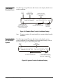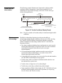
1
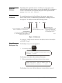
IFC-1010/2020 Technical Manual 448 Operations Section Technical Bulletin Issue Date 1198 IFC-1010/2020 Operations Introduction Page 3 x Location of Content Changes 3 x About the Operation of the Panel 3 x About This Technical Bulletin 5 x About the Passwords 6 x About the Software 7 x About Addresses 7 x About the Backspace Key 7 x About Entering Alphanumerics 8 x About the Walk Test 9 x About the Display Time 9 x About the Print Time 9 x About Priorities 10 x About System Test 11 x About Periodic Test 12 Display Interface Assembly 13 x Normal Operation 13 x Read Status 16 x Display System Configuration 17 x Menu Choice 8: 19 x Point Read 20 x Special Status 23 Prior/Next/Autostep © 1998 Johnson Controls, Inc. Code No. LIT-448100 25 1 www.johnsoncontrols.com Special Function Page 27 x To Select Special Function 27 x Reports 27 x History Buffer 29 Fire Alarms 31 x 32 Acknowledging a Fire Alarm Troubles 33 x Trouble with SLC Devices 33 x Trouble with Disabled Zones 34 x Trouble with the IFC-1010/2020 System 34 x Trouble with the Annunciators 35 x Block Acknowledge 35 x Acknowledging Troubles in Receiving Unit Mode (Block Acknowledge Disabled) 36 x Displaying Current Alarms and Troubles 37 Remote Peripherals 39 x CRT Terminal 39 x Printer 39 Trouble Messages 41 Drift Compensation 45 Application and Clarification Notes 47 2 Operations—IFC-1010/2020 Operations Introduction Location of Content Changes The product that this document supports is UL (Underwriter’s Laboratories) Multiple Listed, which requires that the content of the documentation inherited from the manufacturer remain intact. Minor changes clarify information such as vendor-specific product names and literature names and numbers. More significant changes to the original technical content, such as Nx additions or corrections, are identified with Note Number . For the Note Number content, refer to the Application and Clarification Notes section at the end of this document. About the Operation of the Panel Use of intelligent, addressable detectors and modules provide the operator with precise information on the location of the alarm or trouble, as well as what type of device is reporting the activity. ! WARNING: The IFC-1010/2020 control panel will only operate with Johnson Controls intelligent addressable devices installed. All operating power, as well as data communications to and from intelligent addressable devices, is transmitted on a 2-wire Signaling Line N1 Circuit (SLC) loop that may be wired to meet the requirements of either NFPA (National Fire Protection Association) Style 4 or Style 6 or 7 operation. The IFC-2020 system can be configured with up to ten Loop Interface Boards (LIB) SLC loops and the IFC-1010 system with up to two loops. Each loop is capable of supporting up to 99 intelligent detectors and up to 99 addressable control or monitor modules. A fire alarm in the IFC-1010/2020 is initiated by activation of any of the following devices connected on the SLC: x intelligent smoke or heat detectors (1251J, 2251J, 1551J, 2551J, 2551THJ, 5551J, 5551JR, DH500J, and DH502J) x addressable manual pull stations (BGX-101) x conventional normally open or normally closed contact fire alarm initiating devices connected to addressable M50xMJ monitor modules (or equivalent XPM circuits) Operations—IFC-1010/2020 Operations 3 During an alarm condition, LEDs (Light-Emitting Diodes) on as few as 6 and as many as 99 addressable initiating devices (such as smoke detectors, heat detectors, and M50xMJ modules) and/or output modules may be latched on. A latched on LED on an initiating device indicates that the device has caused an activation signal to be transmitted to the IFC-1010/2020. A latched on LED on an output module indicates that the module has been activated. An activation signal on the IFC-1010/2020 includes fire alarms, security alarms, supervisory conditions, or non-alarm inputs. Note: During loss of primary (AC) power, when the IFC-1010/2020 is operating under secondary power, only the LEDs on intelligent detectors (including DH500J and DH502J duct detectors) will be latched on during a fire alarm. ! CAUTION: The IFC-1010/2020 can be programmed to latch the LEDs on up to 99 addressable devices (such as N4 M50xMJ and M5x0CJ). This software feature can be used only if all installed addressable devices purchased from Johnson Controls after April 1, 1991 are stamped with the code R4 on the product marking label. Use of this feature under any other circumstances can cause the SLC loops to shut down during a fire alarm condition. RA400 Remote LEDs are not permitted for use with this feature (excluding those wired to a DH500J Duct Detector). Use only the RA400Z Remote LED when extending the number of latched on LEDs beyond six. The 2551J Photoelectric Detectors can also have an H code after their model numbers. Note: Detectors have priority over modules. Detectors that come into alarm will assume LED-latch priority over previously-latched module LEDs. Output devices (such as alarm notification appliances and output relays) are controlled by activation of M5x0CJ control modules (or equivalent XPC or XPR circuits) connected along the SLC loop. An addressable control module may serve as a Form-C output relay or as a Notification Appliance Circuit (NAC). 4 Operations—IFC-1010/2020 Operations About This Technical Bulletin This technical bulletin covers the operation of the IFC-1010/2020 Combination Fire/Security Protective Signaling System and the control features available to the operator presented through the perspective of the Display Interface Assembly. (DIA-1010 or DIA-2020, see Figure 3). Following are general terms used for specific part numbers: x PRN is used for PRN-4. x CRT is used for CRT-2. x M5x0CJ is used for M500CJ or M510CJ. x M50xMJ is used for M500MJ, M501MJ, or M502MJ. This chapter refers to M5x0CJ control modules and M50xMJ monitor modules. If XP Series transponders are used, unless otherwise stated, the following substitutions may be made: x M50xMJ monitor modules can be substituted with XPM circuits. x M5x0CJ control modules configured as Form-C contacts (tabs broken) can be substituted with XPR circuits. x M5x0CJ control modules not configured as Form-C contacts can be substituted with XPC circuits. ! WARNING: The XP Transponder may be programmed so that it will revert to local program operation upon loss of communications with the IFC-1010/2020. Therefore, use extreme care when assigning software Type IDs to XP Transponder circuits. For instance, an XP circuit-assigned software Type ID SPSU will initiate a supervisory condition under communication with the IFC-1010/2020, but will result in an alarm condition under local XP operation. Note: For more information, refer to XP Transponder Technical Bulletin (LIT-448180). Operations—IFC-1010/2020 Operations 5 About the Passwords The IFC-1010/2020 functions in one of three levels: Operational Level, Level One, and Level Two. In Operational mode, the operator may perform the following keypad or menu-displayed functions: x Acknowledge alarms, troubles, and restorations (clears). x View acknowledged alarms, troubles, and restorations. x Silence the sounding of fire alarm notification appliances. x Reset the IFC-1010/2020 system. x Test all intelligent addressable detectors in the system. x Test the panel’s LED indicators, Liquid Crystal Display (LCD) terminal, and printer. x Read the status of the entire IFC-1010/2020 system, including the addressable devices. x Print out a report on the status of the system or access the history buffer. Access to menu Levels One and Two require entry of specific passwords. These levels allow an authorized programmer to initialize or alter the programming of the IFC-1010/2020. Level One and Level Two entry requirements are defined as follows: x Alter Status Level One password required x Programming Level Two password required If the main operator of the system requires access to a function that is password protected, contact the local Johnson Controls office for the required passwords. For more information on programming or altering the status of the IFC-1010/2020, refer to IFC-1010/2020 Programming Technical Bulletin (LIT-448060). Whenever the operator selects a menu, the IFC-1010/2020 begins a 1-minute timer. If no key is pressed during this minute, the function selected will be aborted and control will return to the state the panel was in prior to selection of that menu. Note: Unacknowledged points must be acknowledged prior to being reprogrammed. Any new trouble or alarm reports received during N10 programming may disrupt the programming process. 6 Operations—IFC-1010/2020 Operations Depending on the particular release of software in your system, some menu functions and system features may not be operable. If you attempt to execute a function that is not operable, the panel will respond with the message FUNCTION NOT ENABLED. About the Software About Addresses For certain functions such as Read Status, the operator must enter a device, software zone, or annunciator point address. Leading zeroes are not required. The address assumes the following format: LX X(D/M ) Y Y, SLC Loop E n te r “L ” fo llow e d by 1 to 10 for IFC -2 02 0. E n te r “L ” fo llow e d by 1 to 2 fo r IF C -10 10 . ZX XX or AXX PYY S o ftw a re Zo ne E n te r “Z” fo llo w e d b y 1 to 24 0. SLC Loop Device E n te r “D ” for an in te llig en t d ete cto r or “M ” fo r a n ad dre ssa ble m o du le fo llow e d by a n a dd ress in th e ran ge 1 to 9 9. Annunciator Point E n te r “A ” follo w ed b y 1 to 32 fo r th e an nu nciato r m o du le a dd ress, th en “P ” fo llow e d by th e m o du le p oint 1 to 64 . A d drp ic ! Figure 1: Addresses For example, L3M44 must be entered as the address for the 44th module on LIB SLC Loop 3. About the Backspace Key The Backspace key serves two purposes: BACK S PA C E 1. At a menu prompt: PRESS 1=SYS,2=PTREAD,3=ALM,4=TBL,5=DIS, 6=MONON, 7=CLTON : s cintr1 ! The Backspace key aborts the selection of that menu. 2. When entering data or making a selection from a menu: ENTER LXX(D/M)YY, ZXXX OR AXXPYY FOR PT. STATUS (BCKSPC TO ABORT) : L4D3 s cintr2 ! The Backspace key erases the last character, or menu choice entered. Operations—IFC-1010/2020 Operations 7 About Entering Alphanumerics Most of the keys on the DIA (Display Interface Assembly) keypad serve more than one function. For instance, the 3 key is used to enter the digit 3 or the letter D when entering the address of a detector. The IFC-1010/2020 toggles which character appears on the LCD with each successive press of that key. This allows the operator to press one key until the desired character appears. That character is entered into the display whenever the next (different) key is pressed. If two of the characters contained on a key (for instance, the D and the 3) need to be entered in succession, the Alpha Enter key must be used (see the example that follows). After the full address has been entered into the display, press Enter to transfer the display contents to the system for processing. Example: To enter L8D3, K Press L S IG N A L S ILE N C E K Press O O Press D Press Press Press D Press 8 again and the K will change to L. and the letter O appears to the right of the displayed letter L. 8 again to change the letter O to the digit 8. 3 and the letter D appears to the right of the characters L8. The partial address displayed now reads L8D. ALPH A EN TER D Press L S IG N A L S ILE N C E Press and the letter K appears. to enter the letter D into the display. 3 and a second letter D will appear to the right of the characters L8D. The partial address displayed now reads L8DD. 3 again to change the second D to the digit 3. The completed address now reads L8D3. EN TER 8 Operations—IFC-1010/2020 Operations to transfer the display contents to the IFC-1010/2020 system for processing. About the Walk Test The Walk Test function is a service feature that allows 1 person testing of devices on any selected SLC. The Walk Test feature will abort automatically after 15 minutes of inactivity or if inadvertently left enabled N5 by the service representative. About the Display Time The IFC-1010/2020 has a separate time field in the display for each event that occurs in the system. All Systems Normal During periods of no activity, the time field reflects the current time. For IFC-1010/2020 systems interfaced with the Metasys on the N2 or the Metasys Fire Network, the time is synchronized every midnight by the Metasys master time. If a new time is programmed for any IFC-1010/2020 node on the network, all of the IFC nodes will synchronize to that time until the entire Metasys Fire Network is again synchronized at midnight. Single, Unacknowledged Event When an event has occurred but has not been acknowledged, and no other event has occurred, the DIA, CRT, and LCD-80s (if installed) will display the time this event occurred. Multiple, Unacknowledged Events The display will show the actual time that the first unacknowledged event occurred. After the first event is acknowledged, the time shown on the display does not represent the time at which the event occurred, but instead indicates the time at which the event appears. Single/Multiple Previously Acknowledged Events The time shown for an acknowledged event is the time at which that event was last placed in the display by activation of the Ack/Step key (not the time at which the event occurred). About the Print Time Output to the printer for a particular event (such as alarm, trouble, and acknowledgment) includes the time the event was sent to the printer, which, in most cases, is identical to the time the event occurred. In extreme cases, when many events have occurred within a few seconds, the time printed for a particular event may differ from the actual event time by up to one minute. After events have been acknowledged, only the event history table (if enabled) and the system printer will provide a record of N11 the time at which events occurred. Operations—IFC-1010/2020 Operations 9 About Priorities Every event that the IFC-1010/2020 displays is prioritized. This includes the processing of incoming alarm and trouble events, acknowledging events, the clearing of events, and acknowledging the clearing of events (receiving unit operation only). Security alarms will increment the trouble counter on the terminal status line of the CRT. Note: In the IFC-1010/2020, security alarms are processed like fire trouble conditions. The IFC-1010/2020 processes and displays events under the following priorities, highest priority first: 1. Fire Alarms 2. Security Alarms 3. Supervisory Signals 4. Device Troubles 5. Disabled Zones 6. System Troubles 7. Annunciator Troubles 8. Cleared Fire Alarms 9. Cleared Security Alarms 10. Cleared Supervisory Signals 11. Cleared Device Troubles 12. Cleared Disabled Zones 13. Cleared System Troubles 14. Cleared Annunciator Troubles 10 Operations—IFC-1010/2020 Operations In addition, detectors have a higher priority than modules within each detector/module category; the lower the address, the higher the priority (see list below). The display of certain events can be pre-empted by others at the time they are acknowledged. Pay careful attention to the display when acknowledging events. N6 Node 1, Loop 1 Detector 1, Loop 1 Detector 2, Loop 1 Detector 3 … Loop 10 Detector 99 (followed in priority by) Node 1, Loop 1 Module 1, Loop 1 Module 2, Loop 1 Module 3 … Loop 10 Module 99 (followed in priority by) Node 1, Zone 1, Zone 2, Zone 3 … Zone 240 (followed in priority by) Node 1, System Trouble Indices (in Hex) T00, T01, T02…TFF (followed in priority by) Node 1, Annunciator Trouble Indices (in Hex) N00, N01, N02 … NFF About System Test System Test, or Detector Test as it is often referred to, is a manually initiated test of all intelligent detectors installed in the system. When the user presses the System Test key the fire panel performs a chamber test of each intelligent detector to ensure its proper operation. System Test can take up to one minute before displaying its results, There are two types of display: DETECTOR TEST: ALL OK 01+05+00+02+00+80 +25+00+06+00 TOT=119 05:00P 05/55/97 s ys te s t1 Each LIB displays the total number of intelligent devices installed on it, as well as the overall system total. DETECTOR TEST FAIL 110,119,211,213,605, 617,799,815,015,020+ 05:30 05/22/97 s ys te s t2 Each failed device is represented by a three digit number. The first digit indicates the LIB number (0=10), and the last two the device address. If more than ten devices have failed a + is shown after the last detector number. If more than ten detectors failed, the serviceman would have to repair, replace, or disable the ten listed, and then rerun System Test in order to locate the remaining ones. Operations—IFC-1010/2020 Operations 11 About Periodic Test The fire panel performs a periodic automatic chamber test of all intelligent detectors installed in the system to ensure their proper operation. When a detector has failed its automatic chamber test, it will generate a trouble message. The service person would then have to repair or replace the indicated device. 12 Operations—IFC-1010/2020 Operations Display Interface Assembly Normal Operation During normal fire alarm operation when no alarms or troubles exist, the system will display the following: C u stom 4 0-ch ara cter Labe l JOHNSON CONTROLS ALL SYSTEM NORMAL 04:32P 03/01/97 C u rren t Tim e an d D ate H o ur: M in ute A (A M ) o r P(P M ) M o n th/D ay/Ye a r n o rm a lo p Figure 2: Normal Operation The operator can perform the functions associated with the following keys without having to enter a password: A ACK S TE P R EAD S TAT U S S IG N A L S IL EN C E (A description of the READ STATUS and the SPL FUNCT keys follows.) S YS TE M R E SE T S SP L FU NC T S YS TE M TE S T LAMP TE S T K e yp a d Figure 3: Display Interface Assembly (DIA) Operations—IFC-1010/2020 Operations 13 R e fer to Tab le 1 fo r d etails. R e fer to Tab le 2 fo r d etails. A AL L SY ST E M S N O R M AL 1 2:00P 3/0 1/98 AC K ST EP S IG N A L S ILE N C E S Y S TE M RE SE T S Y S TE M TE S T LA M P TE S T B G ALTER STATU S TR O U B LE / S EC U R IT Y A L AR M M ( D IS PL AY TR O U B LE SPL FUN CT S IG N A L S IL EN C E ALPHA BAC K SPAC E ENTER 6 SIGN AL SILENC E 8 9 SYSTEM R ESET 0 BAC K SPAC E AUTO STEP ENTER O 7 ( Y N EXT K Q P U PRO R X J 5 T F ACK STEP I N E 3 4 PRO G D 2 H FIR E A L AR M S C 1 H EAD STATU S A .C . P O W ER R W V Z L SYSTEM TEST SP LAMP TEST inte rfce R e fer to Tab le 3 fo r d etails. R e fer to Figu re 4 fo r d etails. Figure 4: Display Interface Components Table 1: Display Interface Components Component Description Piezo Sounder The local panel piezo sounder provides an audible indication of the system alarm or trouble conditions. The sounder will pulse to indicate the detection of at least one fire alarm condition in the system, and will sound steadily when the system is in trouble. The sounder is silenced when all conditions have been acknowledged. If the sounder sounds steadily, and it cannot be silenced by the acknowledgment of all system alarm/trouble conditions, call your Johnson Controls service representative immediately. 80-character Liquid Crystal Display The LCD displays the current status of the entire IFC-1010/2020 system. While programming the IFC-1010/2020, the LCD provides various system configuration menus and prompts. This display also is illuminated when the IFC-1010/2020 is under AC power. The display will remain illuminated for one minute after the loss of AC power; any keypad or system activity will re-illuminate the display for one minute. Table 2: Display Interface Components Component Description AC Power A green LED will illuminate to indicate that the system is operating from the primary power supply. Fire Alarm A red LED will flash to indicate that the panel has detected at least one fire alarm in the system. The red LED will light steadily when all fire alarms have been acknowledged. The panel LCD text display will provide detailed information on any alarms received. Trouble/ Security Alarm A yellow LED will flash to indicate any unacknowledged change of status in the system. The panel LCD text display will provide detailed information about each change of status signal received. After all change of status conditions have been acknowledged, and while at least one trouble condition still exists, the Trouble/Security Alarm LED will illuminate steadily. Note: Security alarms are treated as fire trouble conditions in this combination fire alarm/security system. Display Trouble A yellow LED will illuminate when a trouble condition is detected in the DIA display assembly. If this LED is illuminated, the contents of the DIA display must be considered invalid. Call your Johnson Controls service representative immediately. Signal Silence A yellow LED will illuminate steadily when all the control modules in the system which can be silenced have been silenced. A flashing yellow LED indicates a partial signal silence condition—some of the control modules that can be silenced have been silenced. 14 Operations—IFC-1010/2020 Operations Table 3: Display Interface Components Component Description Ack Step This key is used to acknowledge system alarm or trouble conditions. When depressed, the operator acknowledges the new status of the device indicated on the LCD text display. Pressing this key will also step the display to the next device in alarm or trouble. After all such system alarm and trouble conditions have been acknowledged, the Ack Step key may be used to step display through the existing system alarm and trouble conditions. Signal Silence This key, during a fire alarm condition, will deactivate all activated control modules that have been programmed to permit signal silencing. System Reset This key is used to clear all system alarm and trouble conditions. If an alarm or trouble condition still exists after System Reset, that alarm/trouble condition will resound the DIA sounder and display the condition on the LCD and LEDs. Note: The function of the key is inhibited until all alarms and troubles have been acknowledged. System Test This key is used to automatically perform a test of all intelligent detectors in the system. Results of the system detector test are then indicated on the panel display. Lamp Test This key is used to perform a test of LEDs on the control panel and to test the panel display. The test will illuminate the panel LEDs in sequence for a timed period and flash the panel display. When the test has been completed, the panel LEDs and the panel display will return to their prior status. Note: These keys and their functions are repeated on the alphanumeric keypad of the DIA. Table 4: Display Interface Components Component Description Auto Step During Read Status, this function key automatically scrolls the display through a list of system conditions such as devices that are in alarm or trouble. Prior, Next During Read Status, these keys allow the user to step forward or backward through a list of system conditions such as devices that are in alarm or trouble. Read Status Allows the status of the entire system to be read, including the status of the loop interface boards, the addressable detectors, and the control and monitor modules. Alter Status Provides access to Level One functions, such as setting the FACP clock. Prog This Level Two function key provides access to Programming mode, for configuring the IFC-1010/2020. SPL Funct This key generates system and installed point reports. Alpha Enter During Programming mode, pressing the Alpha Enter key stores the character displayed and permits the alternate character on that key to be entered next. Backspace Erases the last alphanumeric keypress, or serves as an escape key during programming. Enter Menu selections are entered and programming data is stored in IFC-1010/2020 memory upon pressing this key. Operations—IFC-1010/2020 Operations 15 Read Status The Read Status feature of the IFC-1010/2020 allows the operator to display the status of the entire system. A To execute the Read Status: Press RE AD S TAT U S . The display will show: PRESS 1=SYS,2=PTREAD,3=ALM,4=TBL,5=DIS, 6=MONON,7=CTLON : S cr12 A ! Enter 1 for Display System Configuration. This selection provides information on any of the system parameters programmed into the IFC-1010/2020 - such as the number and style of the loop interface boards, the number of AVPS-24 and/or AVPS-24E and/or APS-6R power supplies, the software zone boundary, the system time delays, and the annunciator modules installed. Enter 2 for Point Read. This selection provides information on the status of any intelligent detector, addressable module, software-defined zone, or annunciator point in the system. Enter 3 for Alarm. This selection provides information on the lowest N2 addressed device or zone in an alarm state. Enter 4 for Trouble. This selection provides information on the lowest N2 addressed device or zone in trouble. Enter 5 for Disable. This selection provides information on the lowest N2 addressed device or zone disabled. Enter 6 for Monitor On. This selection provides information on the lowest N2 addressed non-fire or security monitor module activated. Enter 7 for Control On. This selection provides information on the lowest N2 addressed control module activated. Note: Read Status Options 3, 4, 5, 6, and 7 and the Point Read option use N12 the same format to display their indicated point information. For an IFC-1010/2020 FACP on the Metasys Fire Network System, always perform Read Status operations from a Fire Operator Workstation (OWS). Never attempt to perform Read Status operations from a local panel when the Fire OWS is simultaneously attempting to do so. 16 Operations—IFC-1010/2020 Operations Display System Configuration Read Status Menu Option 1 Selecting 1 from the Read Status menu allows the operator to review the various system parameters entered into the IFC-1010/2020. The System Configuration menu: PRESS 1=INST,2=STY,3=TDLY,4=AVPS,5=ZBND, 6=EXTEQ, 7=LOCP, 8=ISIB, 9=PARM : s cr1 2 b ! Note that when 4 is chosen from the menu, the total number of AVPS and/or APS-6R power supplies will be displayed. E nter M enu C hoice 1 S ta tus D isplaye d: THESE LIB BOARDS ARE INSTALLED: 1=Y,2=Y,3=Y,4=Y,5=N,6=N,7=N,8=N,9=N,10=N Y = In stalled 2 N = N ot Installed THE SLC LOOP STYLES ARE AS FOLLOWS: 1=6,2=6,3=6,4=6,5=4,6=4,7=4,8=4,9=4,10=4 Th e de fa ult value fo r S LC loo p s no t insta lle d is N F PA S tyle 4 . 3 VER=60, SIL=045, CUT=0000 V E R =A larm Verifica tio n Tim e (in se co nd s) S IL= S ig na l-S ile n ce In hibit Tim e (in se con ds) C U T =S ign al C u t-o ut Tim e (in seco nd s) 4 5 THERE ARE CURRENTLY 04 AVPS-24 INSTALLED IN THE SYSTEM ZONES 001 - 200 ARE FORWARD ACTIVATED ZONES 201 - 240 ARE REVERSED ACTIVATED s cr1 2 _ a Figure 5a: Read Status Menu Option 1 (Continued on next page) Operations—IFC-1010/2020 Operations 17 6 TS=N SL=N APM=N,CMR=N,NAR=N LEDL=N,PEC=N,BC=N,PTI=N,RPT=N TS =is the con ne ctio n to th e term in a l sup e rvise d? (If T S =N , th e term ina l w ill no t au dibly in dica te state ch an ge s [i.e., n o B ell ch ara cters w ill be sen t)]. S L =Is the S tatu s Line o ptio n e na b led ? A P M = is th e co nn e ction to the a uxilia ry printe r m o nitored ? N A R = Is “N O N A ”/”N O A ” m o n ito r m od u le state rep orting e na bled ? L E D L= LE D la tche s on m o re activa ted a dd re ssable d evice s? P E C =C o ntinu e to tra nsm it un de r p rin te r e rror con ditio ns? P B C =Is b id ire ctio na l co py e na bled ? P T I=Is the p rm ary p rin te r tro ub le inh ib itie d? R P T =A re p rin te r re po rts d ire cted to te rm in al o utput? 7 THESE LIB BOARDS ARE INSTALLED: 1=Y,2=Y,3=Y,4=Y,5=N,6=N,7=N,8=N,9=N,10=N D P X =Is the piezo disa b le d d uring p rog ra m m ing ? L M D = Lo cal M od e D ecte ctor ad dre ss. L M M = Lo ca l M o de M o nitor m o d ule a dd re ss. L M C = Lo cal M od e C on tro l m o du le ad d ress. 7 2A = P ro te cte d pre m ises (loca l) fire a larm system . 7 2B = A u xilia ry fire alarm se rvice 7 2C = D o no use 7 2D = D o no use 7 1= D o n o use L =L ea d A cid N = N i-cad R C = P ro prieta ry sup ervising statio n o r ce ntra l station re ceiving un it. B T Y P = Type o f b attery insta lled in the syste m . B C A P =N i=cad b attery ca pa city. B S B Y =N i=ca d b a tte ry stan db y tim e . E R M = Is eve nt rem in d er e n ab le d? B L N =Is de vice b linkin g en ab le d? PA L =Is p re-ala rm o ptio n e na bled ? 8 PRESS 1=INSTL,2=ANN,3=XINT,4=DACT : O ptio n 8 p ro vide s yo u w ith a R e ad S tatu s sub m enu for view ing th e statu s o f th e in tellige nt S IB , insta lle d an nu nciato rs, e xtern al inte rfa ce , or D A C T. Th is m e nu is d escrib ed late r. 9 HINZNDET=Z150,LOZNDET=Z001 SERPT=Y,DRIFT=Y,PGR=Y,MDM=Y,NAM=N,RP=Y H IZ N D E T =H ig h zo n e for da y/nigh t d etecto r sen sitivity. L OZ N E D T =L ow zo ne fo r d ay/n ig ht de te ctor se nsitivity. S E R P T= Is “S A C M ”/”S E Q M ” m o nito r m od ule state re po rting en a bled ? D R IF T= Is drift co m pe nsa tio n en ab le d? P G R = Is PA G E -1 e na bled ? M D M =Is m o de m en ab le d? N A M = Is th e N A M -23 2 en ab le d? R P = Is ra pid p o lling e na bled ? s cr1 2 _ b N7, N9 Figure 5b (Cont.): Read Status Menu Option 1 18 Operations—IFC-1010/2020 Operations Menu Choice 8: ISIB E nter M enu C hoice 1 S ta tus D isplaye d: ISIB=Y IS IB =Is the Inte llig en t S e rial In terface B oa rd in stalle d? N o te: IS IB s availa ble for the IF C -10 1 0/2 02 0 syste m in clud e the S IB -20 48 A , S IB -N E T, a nd S IB -N 2. Fo r a n IFC -1 01 0 /20 20 con ne cted to a Fire N etw ork syste m h ow e ve r, the o nly IS IB th at can be u se d is th e S IB -N E T. If a S IB -N E T is no t in stalle d, th e F ire N e tw o rk’s spe cific fun ctio ns can no t be p rog ram m ed o r re ad u nd er R ea d S ta tus. 2 THESE ANNUNCIATORS ARE INSTALLED: (PRESS ENTER TO CONTINUE UNTIL DONE) D u e to its size, th e A nn un ciator R ea d S ta tus d isp lay is se pa ra ted into tw o scree ns, illustra te d b elow. P re ssing < E nter> in vokes th e ne xt d isplay. 1=Y,2=N,3=N, 4=N, 5=Y, 6=Y, 7=N, 8=N, 9=Y,10=N,11=N,12=Y,13=Y,14=Y,15=N,16=N, 17=Y,18=Y,19=Y,20=N,21=N,22=N,23=N,24=N, 25=N,26=N,27=N,28=N,29=N,30=N,31=N,32=N 3 UPDN=N,ADDR=010,DBID=BC00D148 MIBA=H,MIBB=H,PORTS=2 U P D N = Is th e A C S P ort up lo ad /d ow n lo ad e na bled ? *A D D R = FA C Fire N etw ork a dd ress. *D B ID =D a tab a se id e ntifie r. *M ID A = M IB -W /W F th resh old for C ha nn el A . (O n the M IB -W F, o nly th e C h an n el A thre sh old se tting is u sed .) *M IB B = M IB -W th re sh old for C h an ne l B . *P O R TS = N um b er of da ta po rts m on itore d. *Th ese item s are F ire N e tw ork sp ecific fu nction s an d a re o nly disp la ye d w he n a S IB -N E T is in stalled . 4 DACT=01 D A C T =B a se a d dre ss o f the U D A C T (b la nk fo r n on e in stalled ). s cr1 2 _ c Figure 6: Read Status Menu Option 8 Operations—IFC-1010/2020 Operations 19 Point Read Read Status Menu Option 2 Selecting 2 from the Read Status menu allows the operator to review the various detector, module, software zone, or annunciator point parameters entered into the system. The system prompts the operator for the address of the point to be read: ENTER LXX(D/M)YY, ZXXX OR AXXPYY FOR PT. STATUS (BCKSPC TO ABORT) : s cr1 2 r! Upon entering the SLC or annunciator address/zone number, the system will display a distinct screen format, depending on the particular type of device being read, as illustrated below: Note: After a 1-minute timeout, the Control-By-Event (CBE) and the annunciator point mapped address appears for devices and zones. Cooperative Control-By-Event (CCBE) appears for reverse N8 zones. To display this information immediately, press Enter after the status line appears. Detectors S tatu s: D IS A B L E ,A L A R M , T R O U B L,N O R M A L S o ftw a re Typ e ID NORMAL SMOKE(ION) D A T K SH D e vice D isa bled D e vice in A larm Tra cking S e le cted D e vice in Tro ub le 2 0-cha ra cter C u stom L ab el COMPUTER ROOM SMOKE V000 H 034 L02D26 Ve rificatio n C o un te r A d dre ss P e rcen tag e of A larm T hre sho ld S e nsitivity S electio n : L ow, M ed iu m , H ig h D a y/N ig ht D etecto r S e nsitivity S e tting : L ow, M e diu m , H igh s cr1 2 s ! Figure 7: Detectors Note: A detector may be in periodic test during a Read Status. In this case, the detector status will be normal but the percentage of alarm threshold will be greater than 100%. If this happens, wait one minute, then perform another Read Status. 20 Operations—IFC-1010/2020 Operations Detector Verification If detector verification is enabled for this point, the V indicator appears and the 3-digit counter shows the number of times the verification timer was activated for the point without going into alarm. The counter returns to zero when power is cycled to the IFC-1010/2020. If you disable verification, the counter will retain its last value. If verification is not enabled for this point, the V indicator does not appear; however, the 3digit number still appears. Note that the counter does not increment unless verification is enabled. Control Modules S tatu s: D IS A B L , O N , T R O U B L , O FF, *O F H O O K , N O R M AL 2 0-cha ra cter C u stom L ab el S o ftw a re Typ e ID DISABL CONTROL D CF A T W D e vice D isa bled C o ntrol M od ule C O = On C F= O ff COMPUTER ROOM BELL S L01M36 S ign al S ile nce E n ab le d D e vice in Tro ub le D e vice in A ctiva te d A d dre ss W a lk Test S e le cted *A n O FH O O K status ind icate s th at a te lep h on e o ff-h oo k (rin g-in) sign al h as b ee n re ce ived , bu t h as n ot be en answ e red b y the o pe ra tor at th e fire figh te rs telep h on e A C S sw itch bo a rd. s cr1 2 t! Figure 8: Control Modules Operations—IFC-1010/2020 Operations 21 Monitor Modules Fire S ta tu s: D IS A B L, TR O U B L, N O R M A L N o n-F ire an d S e cu rity S ta tus: D IS A B L, O N TR O U BL, O FF 2 0-cha ra cter C u stom L ab el S o ftw a re Typ e ID NORMAL MONITOR D MO A T K D e vice D isa bled BASEMENT SMOKES L05M12 S ign al S ile nce E n ab le d D e vice in Tro ub le M on itor M od ule O n (N on-F ire a nd Se curity type s O nly) A d dre ss Tra cking S e le cted D e vice A ctiva te d (Active in a N o n-Fire M o de) s cr1 2 u ! Figure 9: Monitor Modules Software Zones S tatu s: D IS A B L , T R O U B L, N O R M A L S o ftw a re Typ e ID 2 0-cha ra cter C u stom L ab el ALARM: FORWARD ZONE ATTIC DEVICE ZONE D A T Z023 Zo ne Zo ne in D isa bled A larm Zo ne in Tro ub le Figure 10: Software Zones 22 Operations—IFC-1010/2020 Operations A d dre ss s cr1 2 v ! Annunciator Points Annunciator Points S tatu s: O N , TR O U B L ,O F F, R E Q E S T*, or b la nk S o ftw a re Typ e ID OFF ANN CONTROL 2 0-cha ra cter C u stom L ab el ANNUNCIATOR ONE A01P23 *A n R E Q E S T sta tu s in dicate s tha t a telep ho ne o ff-ho ok (rin g-in) sign al ha s be en re ce ive d, an d an sw e re d b y th e op era to r a t th e fire fig hte rs te le ph on e A C S sw itchb oa rd , b ut ha s no t b ee n co n ne cted to th e te lep h on e lin e. A d dre ss s cr1 2 w ! Figure 11: Annunciator Points Special Status Option 3 provides information on devices or zones in an alarm state. Option 4 provides information on devices or zones in a trouble state. Option 5 provides information on disabled devices or zones. Option 6 provides information on activated non-fire or security monitor modules. Option 7 provides information on activated control modules. Selecting 3, 4, or 5 from the Read Status menu prompts the operator to choose between zones and devices. The following example performs a search for the lowest devices in a fire alarm state. PRESS 1=SYS,2=PTREAD,3=ALM,4=TBL,5=DIS, 6=MONON,7=CTLON : 3 DO YOU WANT ZONE OR DEVICE STATUS? (Y=ZONE, N=DEVICE (BCKSPC TO ABORT)): N ALARM: SMOKE(ION) A COMPUTER ROOM SMOKE M 034 L02D26 s cr1 2 x ! Figure 12: Special Status Note: The Control-By-Event and the annunciator point mapped address appears for devices and zones after a one minute timeout. In a Metasys Fire Network system, Cooperative Control-By-Event equations are displayed for reverse zones. To display this information immediately, press Enter after the status line appears. Operations—IFC-1010/2020 Operations 23 24 Operations—IFC-1010/2020 Operations Prior/Next/Autostep The Prior, Next and Autostep keys are used with Options 2 through 7 of the Read Status menu. Upon selection of one of these options, an address range is defined by the IFC-1010/2020 for which similar searches can be performed using the Prior, Next, and Autostep keys. These functions enhance and speed up the search process, because they eliminate the need to re-enter the Read Status menu for the same function being repeating. Prior - Searches the database in a reverse direction from the current address (refer to Note). Next - Searches the database in a forward direction from the current address (refer to Note). Autostep - Performs an automatic search of the database in the forward direction from the current address with a two second display of status line, followed by a two second display of the CBE and annunciator point mapped address, for each of the points found. (The CCBE equation appears for reverse zones on the Metasys Fire Network system.) Note: The Control-By-Event and the annunciator point mapped address appears for devices and zones after a one minute timeout. The Cooperative Control-By-Event appears for reverse zones. To display this information immediately, press Enter after the status line appears. S tarting S earch A ddress P rior C urrent A ddress N e xt/A u toste p E nding S earch A ddress s ec 2 p ic Figure 13: Database Search The Autostep key can be used as an alternate method for generating special reports. Operations—IFC-1010/2020 Operations 25 26 Operations—IFC-1010/2020 Operations Special Function The Special Function feature of the IFC-1010/2020 allows the operator to generate IFC-1010/2020 status reports or view the IFC-1010/2020 History Buffer. To Select Special Function To select the Special Function feature: S Press SPL FUN CT . The display will show: PRESS 1=RPTS,2=HIS : s cr3 a Reports SPL FUNCT Menu Option 1 PRESS 1=SYS,2=POINT,3=ALM,4=TBL,5=DIS, 6=MONON, 7=CLTON : sc r3 b Enter 1 for a System Configuration report, 2 for an Installed Point report, 3 for a Fire Alarm report, 4 for a Trouble report, 5 for a Disable report, 6 for a Monitor Module On report (including non-fire and security monitor modules), or 7 for a Control Module On report. The display will show: PRESS 1=REQUEST,2=ABORT : s cr3 e Enter 1 to execute the report or 2 to abort a report already in progress. Note: Only one report can be conducted at any one time. The reports are not displayed on the DIA. Reports are either displayed on the CRT and/or printed by the printer, depending on whether or not printer reports are redirected to the CRT during programming. An example of a report printout is illustrated in Figure 14. The Special Function report printouts (refer to Figure 14) have the same display format as the Point Read option under Read Status. For a description of the various report fields, refer to Point Read. Operations—IFC-1010/2020 Operations 27 P R E S S 1 =R P T S ,2 =H IS : 1 P R E S S 1 =S Y S ,2 -P O IN T,3 =A L M ,4= TB L ,5 -D IS ,6= M O N O N ,7=C TL O N :1 P R E S S 1 =R E Q U E S T,2= A B O R T :1 ** S Y S TE M C ON F IG U R ATION R E P O R T B E G IN ** 0 4:32 P 0 3/0 1/97 TH E S E L IB B O A R D S A R E IN S TA L LE D :1 =Y,2 =N ,3=N ,4= N ,5 =N ,6 =N ,7= N ,8 =N ,9 =N ,10 =N TH E S L C LO O P S TY L E S A R E A S F O LL O W S :1 =4 ,2 =4 ,3=4,4= 4,5 =4 ,6 =4 ,7 =4,8= 4,9= 4,1 0= 4 V E R =05 ,S IL= 00 5,C U T= 05 04 TH E R E A R E C U R R E N T LY 0 0 AV P S -2 4 IN S TA L LE D IN T H E S Y S TE M ZO N E S 0 01 - 0 02 A R E FO R W A R D A C TIVATE D ZO N E S 20 1-2 40 A R E R E V E R S E A C TIVATE D TS =N S L= Y A P M =Y,C M R = Y,N A R = Y,LE D L= N ,P E C = N ,BC = N ,P T I= N ,R P T= N D P Z =N ,L M D =2 0,LM M =2 0,L M C =2 0,7 2 A B C D ,7 1,R C ,B T Y P = N ,B C A P =1 2,B S B Y = 48 ,E R M = Y,B LN =Y,PA L =N IS IB =Y TH E S E A N N U N C IATO R S A R E IN S TA LL E D : (P R E S S E NT E R TO C O N T IN U E U N TIL D O N E) 1 =N ,2 =N ,3= N ,4= N ,5 =N ,6= N ,7 =N ,8 =N 9 =N ,10 =N ,11= N ,12 =N ,13 =N ,14 =N ,1 5= N ,1 6= N 1 7= N ,18 =N ,19 =N ,2 0 =N ,2 1= N ,2 2= N ,2 3=N ,24 =N ,25 =N ,2 6 =N ,2 7= N ,2 8= N ,29 =N ,30 =N .31 =N ,3 2 =N U P D N = N ,A D D R =0 10 ,D B ID = B C 0 0D 1 48 , M IB A = H M IB B= H ,P O R TS = 2 D A C T =0 1 H IZ N D E T= Z1 50 ,L OZ N D E T =Z0 01 S E R P T= Y,D R IF T=Y,P G R = Y,M D M = Y,N A M =N ,R P =N *** S Y S TE M C O N F IG U R ATIO N R E P O R T E N D *** P R E S S 1 =R P T,2 =H IS :1 P R E S S 1= S Y S ,2= P O IN T,3 =A L M ,4 =TB L,5 =D IS ,6 =M O N O N ,7=C T LO N : 2 P R E S S 1 =R E Q U E S T,2= A B O R T :1 *** IN S TA LL E D P O IN T R E P O RT B E G IN *** 0 4:3 2P 03 /0 1/9 7 A L A R M : F O RW A R D ZO N E , FIR S T F LO O R A Z0 01 () A 0 1P 01 A 01 P 0 2 D IS A B L R E V E R S E Z O N E S E C O N D F LO O R D T Z2 02 OR( ) A 01 P 0 2 OR ( ) A L A R M : S M O K E (IO N ) (Z0 1 ) O FF IC E A R E A A S H V 01 0 H 0 45 TR O U B L S M O K E (P H O TO ) FA C TO RY (Z0 2 ) T N O R M A L H E AT (A N A L O G) M A IN TE N A N C E (Z0 1 ) N O R M A L M ON ITOR (Z0 1 ) O N C O N TR O L O R (Z0 1) O FF C O N TR O L O R (Z0 1) FIR S T A ID FIR S T FL O O R S E C O N D FL O O R S H V 00 0 H 04 5 S H V 00 0 H 04 5 L 0 1D 0 A 0 1P 03 L 01 D 02 A 01 P 03 L 01 D 03 A 01 P 0 3 K L 0 1M 01 A 01 P 04 CO W S L0 1 M 0 2 A 0 1P 05 CF W S L0 1M 0 3 A 0 1P 06 ON A N N ZO N E B U IL D IN G O N E D IS A B L A N N ZO N E B U IL D IN G ON E ON A N N D E T E C TO R B U ILD IN G O N E O FF A N N M O N ITO R B U ILD IN G O N E ON A N N C O N TR O L B U ILD IN G O N E O FF ANN CONTROL B U ILD IN G O N E *** IN S TA LL E D P O IN T R E P O RT E N D *** A 0 1P 01 A 01 P 02 A 01 P 03 A 01 P 04 A 01 P 0 5 A 01 P 06 04 :3 2P 03 /0 1/9 7 P rn to u t-3 Figure 14: IFC-1010/2020 Special Function Report Printout 28 Operations—IFC-1010/2020 Operations History Buffer Read Status Menu Option 2 PRESS 1=PRINT,2=DISPLAY,3=STEP,4=RANGE/ STATUS : sc r3 c ! Choices 1, 2, and 3 will prompt the user for the beginning and end of the History Buffer range. The maximum number of events that the system can save in the History Buffer is 400. Press 1 to produce a printed report of the History Buffer. An example of a History Buffer printout is illustrated in Figure 15. Press 2 to perform an automatic display of the History Buffer on the DIA and CRT terminal (if employed). Press 3 to perform a manual display of the History Buffer on the DIA and CRT. Use the Enter key (on DIA) or Return key (on CRT) to advance the display. Press 4 to display the History Buffer range (the number of entries contained in the buffer), and current status (active/inactive). Operations—IFC-1010/2020 Operations 29 To differentiate between History Buffer printouts (refer to Figure 15) and system printouts (refer to Figure 14), the colon (:) in the time field is replaced by the semicolon (;). P R E S S 1 =R P TS , 2=H IS P R E S S 1 =P R IN T, 2 =D IS P L AY, 3 =S T E P, 4 =R A N G E /S TAT U S E N T E R F IR S T E V E NT (1 - 00 8) E N T E R L A S T E V E N T (00 1 - 00 8 ) ********** H IS TO R Y RE P O RT B E GIN ********** 0 4:32 P 0 3/01 /9 7 A L A R M : S M O K E (IO N ) D E T E C TO R O N E 04 :3 2P 03 /0 1/9 7 A C K A L S M O K E (IO N ) D E TE C TO R O N E 04 :32 P 0 3 /01 /9 7 S IG N A L S IL E NC E REQUESTED 0 4:3 2 P 0 3/0 1 /97 S Y S TE M R E S ET A C TIVATE D 0 4 :32 P 0 3/01 /9 7 04 :3 2P 03 /0 1/9 7 C L R A L S M O K E (IO N ) D E TE C TO R O N E 04 :32 P 0 3 /01 /9 7 A C K A L S M O K E (IO N ) D E TE C TO R O N E N O TIFIE R TE S T S YS T E M O N E A LL SY S TE M S N O R M A L 04 :3 2P 03 /0 1/9 7 D E T E C TO R T E S T:AL L O K 02 +0 0+ 0 0+ 00 +0 0+00 +0 0+ 00 +0 0+ 0 0 TO T= 00 2 04 :32P 03 /01 /9 7 ********** H IS TO R Y RE P O RT E N D ********** 0 4:3 2P 0 3/0 1/97 :2 :1 :1 :8 1 01 10 1 1 01 10 1 P R IN T2 Figure 15: IFC-1010/2020 Special Function History Buffer Printout 30 Operations—IFC-1010/2020 Operations Fire Alarms The following example illustrates the system format used to display fire alarm conditions: D e tecto rs: FIX E D P H O T D FIX E D TH E R D H E A D (A N A LO G ) IO N D U C T D E T S M O K E (IO N ) S M O K E IO N H P S M O K E IO N L P S M O K E (P H O TO ) D e vice S tatu s D e vice Typ e ID M od ules: M ON NORM CLD M O N P U L L S TA M O N ITO R P U L L S TATIO N S M O K E (C O N V ) W ATE R FL O W C u stom D e vice L a be l th at w a s en tered du rin g p rog ram m in g. ALARM: SMOKE(PHOTO) COMPUTER ROOM FOURTEENTH FLOOR 04:32P 03/01/97 124 S o ftw a re Zo ne L ab el o f th e first so ftw are zon e th at th e de vice w a s m ap ped to d uring p rog ram m in g . TIm e a nd D a te H o ur:M inu te M on th /D a y/Yea r D e vice A d dre ss in the R a ng e 01 -99 L oo p N um be r in the R an g e 0 -9 , w ith 0= Lo op 1 0. s ec 4 p ic ! Figure 16: Fire Alarm Conditions Display Note: The piezo sounder will pulse for fire alarm conditions. Operations—IFC-1010/2020 Operations 31 Acknowledging a Fire Alarm To acknowledge a fire alarm condition at the panel: ACK S TEP and the Alarm device status will change to ACK AL Press (Acknowledged Fire Alarm). When the fire alarm condition clears (either automatically in the case of devices programmed for tracking, or by the pressing of the System Reset key), the panel will display CLR AL and the piezo will resound. To acknowledge the clearing of a fire alarm: ACK S TEP Press and the CLR AL device status will change to ACL AL (Acknowledged Clear Fire Alarm). When multiple events have occurred, the system will display the first event that occurred (with the exception that the first fire alarm will always override any previous trouble). When the Ack Step key is pressed, the operator will have acknowledged the highest priority event, not necessarily the event that is being displayed on the CRT monitor and DIA. The Acknowledge message for the first prioritized event will be displayed for several seconds, followed by display of the next priority unacknowledged event. Notes: The piezo sounder will be silenced only after all events have been acknowledged. Security alarms are treated like fire trouble conditions in the IFC-1010/2020. For an IFC-1010/2020 panel on the Metasys Fire Network system, acknowledgment of any event may be accomplished from the local fire alarm panel, Intelligent Network Annunciator (INA), or Fire OWS. Acknowledging alarms and events from any of these locations automatically provides acknowledgment at all locations. Fire alarm signals are acknowledged individually at the local fire alarm panel, Fire OWS, or INA. If the same event on the same point occurs on multiple nodes, the event on the node with the lowest node address has the highest priority. For more information on priorities and acknowledging events on the Fire Network system, refer to the Metasys Intelligent Fire Network Technical Bulletin (LIT-448196); Fire Operator Workstation (Fire OWS) Technical Bulletin (LIT-636014); and the Fire OWS section of the Metasys Operator Workstation User’s Manual (FAN 634). 32 Operations—IFC-1010/2020 Operations Troubles Trouble with SLC Devices The following example illustrates the format used to display device trouble conditions: Device Type: M od ules: G N A LA R M F O R C ACCESS M ONTR G N S U P R F OR C ALARM S PEND G N T R B L FO R C A R E A M O N ITO R G N W AT FO R C CMX CONTROL G N W AT E R F LW CMX FORM C M ON NORM CLD C O N TR OL M O N P U L L S TA DACT CONNECT M O N ITO R E Q U IP M O N ITR M O N ITO R PA G E FO R M C M A N U A L N O N A LA R M FO R M C R E L AY N O N A LM M O N GENER AL PEND PA G E G N A LA R M P O W E R (C O N V ) G N A LA R M E V C C u stom D e vice L ab el th at w as e ntere d du rin g D e vice Typ e p rog ram m in g. D e tecto rs: FIX E D P H O T D FIX E D T H E R D H E A D (A N A LO G ) IO N D U C T D E T S M O K E (IO N ) S M O K E IO N H P S M O K E IO N L P S M O K E (P H O TO ) D e vice S tatu s P U L L S TATIO N S M O K E (C O N V ) SPEAKER S P R N K LR M N TR SPRVSRY M NTR S Y S TE M M O N T R TE LE P H O N E TR B L M O N ITO R TR B LS P E N D TR O U B LE TR O U B LE FO R C W ATE R FL O W TROUBL SMOKE(PHOTO) COMPUTER ROOM Z087 MAINTENANCE REQ 04:32P 03/01/97 124 S o ftw a re Zo ne L ab el o f th e first so ftw a re zon e th at th e d e vice w a s m a pp e d to d uring p rog ram m in g. Type of Trouble: TIm e a nd D a te H o ur:M inu te M on th/D ay/Ye a r D e tecto rs: D E T FA IL E D TE S T D E V IC E D IS A B L E D D R IF T TO L E R A N C E IN VA L ID R E P LY L OW C H A M B E R VA L M A IN T E N A N C E R E Q P R E -A LA R M A L E RT D e vice A d dre ss in th e R a ng e 0 1 -99 SLC Number in th e R an ge 0 -9, w ith 0= S L C 10 . S E C U R ITY N O C O M S E C U R ITY TA M P E R S H O R T C IR C U IT S P R N K LR TR O U B L E S U P RV S R Y S IG N A L s ec 5 l! Figure 17: Device Trouble Conditions Display Note: The piezo sounder will sound steadily for unacknowledged trouble conditions. Operations—IFC-1010/2020 Operations 33 Trouble with Disabled Zones The following example illustrates the format used to display disabled zone trouble conditions: D e vice S tatu s D e vice Typ e FO R W A R D ZO N E R E V E R S E ZO N E C u stom Z on e L ab e l th at w a s e n tere d du rin g p rog ram m in g. TROUBL FORWARD ZONE ZONE DISABLED S o ftw a re Zo ne L ab el o f th e first so ftw are zon e th at th e de vice w a s m a p pe d to d uring p rog ram m in g. FIRST FLOOR 04:32P 03/01/97 Z001 Tim e a nd D a te H o ur:M inu te M on th /D ay/Yea r Zo ne A dd ress in the R a ng e Z0 01 -Z2 4 0 s ec 5 2 ! Figure 18: Disabled Zone Trouble Conditions Display Note: The piezo sounder will sound steadily for unacknowledged trouble conditions. Trouble with the IFC-1010/2020 System The following example illustrates the format used to display system trouble conditions. For an explanation of some trouble messages, refer to the Trouble Messages section of this publication. S p ecific Tro ub le M essag e D e vice S tatu s TROUBL CASTASTROPHIC LOOP INTERFACE BOARD 2 COMMUNICATION FLT 04:32P 03/01/97 T19 Tim e a nd D a te H o ur:M inu te M on th /D ay/Yea r Tro ub le In de x P ro vid e this ind e x to your Joh nso n C o n trols Field S up po rt S e rvices fo r trou blesh oo tin g. s ec 5 3 ! Figure 19: System Trouble Conditions Display 34 Operations—IFC-1010/2020 Operations Trouble with the Annunciators The following example illustrates the format used to display trouble conditions with the Annunciator Control System modules. For an explanation of some trouble messages, refer to the Trouble Messages section of this publication. S p ecific Tro ub le M essag e D e vice S tatu s TROUBL ANNUNCIATOR 01 INSTALLATION ERROR MAIN LOBBY 04:32P 03/01/97 N00 Tim e a nd D a te H o ur:M inu te M on th /D ay/Yea r C u stom A n nu n ciato r L ab el U ser de fin ed d uring p rog ra m m ing . Tro ub le In de x P ro vide this ind ex to yo ur Joh nso n C o ntrols Fie ld S u p po rt S ervices fo r trou blesho otin g. s ec 5 4 ! Figure 20: Trouble Conditions Display Format Note: The piezo sounder will sound steadily for unacknowledged trouble conditions. Block Acknowledge The Block Acknowledge function gives the user the ability to acknowledge multiple trouble conditions with one press of the Ack Step key. The IFC-1010/2020 Block Acknowledge function is normally enabled. With Block Acknowledge enabled, the IFC-1010/2020 will function as follows: x Fire alarm conditions including clears (tracking devices only) must be acknowledged individually as described earlier. Fire alarm conditions restored by pressing the System Reset key do not require acknowledgment. x All current unacknowledged conditions must be processed by the system before Block Acknowledge is executed (events will be acknowledged individually until then). x Acknowledged Event messages are not recorded for individual troubles once the Block Acknowledge message appears. x Trouble clears will be recorded for individual troubles that have not been initiated by a system reset. x Trouble clears no longer have to be acknowledged. x Troubles may come and go without being acknowledged. x Upon completion of Block Acknowledge, the IFC-1010/2020 will enter its display acknowledged events mode of operation (see Displaying Current Alarms and Troubles section). Operations—IFC-1010/2020 Operations 35 To disable the Block Acknowledge function, refer to the local parameters NFPA programming section in IFC-1010/2020 Programming Technical Bulletin (LIT-448060). If the IFC-1010/2020 Block Acknowledge function is disabled, the IFC-1010/2020 will process alarm and trouble conditions in Receiving Unit mode. See the Caution note that follows for restrictions. ACK S TEP Press appear: to execute Block Acknowledge. The following message will *********** BLOCK ACKNOWLEDGE *********** 04:32P 03/01/97 s ec 5 5 ! ! Acknowledging Troubles in Receiving Unit Mode (Block Acknowledge Disabled) CAUTION: For an IFC-1010/2020 connected to a Metasys Fire Network system operating as a Proprietary Fire Alarm System and which also includes a Fire OWS, Block Acknowledge is not permitted under the UL Listing. Therefore, all IFC and INA panel nodes should be programmed for the Receive mode of operation and the Fire OWS Block Acknowledge disabled (see the Fire Operator Workstation (Fire OWS) Technical Bulletin (LIT-636014). All nodes must be operated in the same mode. The Receiving Unit mode of operation is required for all NFPA Proprietary Supervising Station and Central Station Receiving Units. To acknowledge a device, zone, system, or annunciator module trouble condition: ACK S TEP Press and the TROUBL status will change to ACK TB (Acknowledged Trouble). When the trouble condition clears, the panel will display CLR TB and the piezo will sound again. To acknowledge the clearing of a trouble condition: ACK S TEP and the CLR TB status will change to ACL TB Push (Acknowledged Clear Trouble). 36 Operations—IFC-1010/2020 Operations When multiple events have occurred, the IFC-1010/2020 will display the first event that occurred (with the exception that the first fire alarm will always override any previous non-sprinkler supervisory trouble). When the Ack Step key is pressed, the operator will have acknowledged the highest priority event, not necessarily the event that appears on the CRT monitor and DIA. The acknowledged message for the first prioritized event will be displayed for several seconds, followed by display of the next priority unacknowledged event. Note: The piezo sounder will be silenced only after all events have been acknowledged. Displaying Current Alarms and Troubles To display alarms and troubles that have been acknowledged but not cleared: ACK S TEP Press and the next event in IFC-1010/2020 memory will appear on the LCD. All events in memory can be reviewed by repeatedly pressing the Ack Step key. Operations—IFC-1010/2020 Operations 37 38 Operations—IFC-1010/2020 Operations Remote Peripherals The IFC-1010/2020 will support the installation of optional remote video display terminals and printers. CRT Terminal The CRT terminal displays all system information. The CRT can also display system reports if printer reports are redirected to the CRT during programming. The CRT is provided with a keyboard that can be used to program the IFC-1010/2020. Local Applications The keyboard can be used to operate the IFC-1010/2020 provided the N3 keyboard is either removed or locked up when not in use. Receiving Unit Applications If employed under NFPA 72-1996 Proprietary Fire Alarm System (Receiving Unit) applications, the keyboard cannot be removed or locked up. The keyboard must remain connected and operationally functional in the system. Printer The printer can be used to provide a permanent record of all system events. Alarms, troubles, and acknowledgments are recorded as they occur in the system. In addition, the printer can be used to print out status information and system reports. Operations—IFC-1010/2020 Operations 39 40 Operations—IFC-1010/2020 Operations Trouble Messages Many of the IFC-1010/2020 device, zone, system and annunciator trouble messages are self-explanatory. Those messages needing further clarification are listed below. If the system is displaying a message that is not self-explanatory, and is not listed here, contact Johnson Controls. CAT. COMM. FAULT Catastrophic communications failure - the annunciator associated with this message is no longer functioning. The connection may be broken. CAT. FAIL. INCOMPATIBLE SOFTWARE OR INVALID CBE The panel is operating under an earlier version of software after newer software features have been programmed into the system. Contact the factory to establish valid software compatibility. Complete reprogramming of system Control-By-Event (CBE) equations may be required. CATASTROPHIC LOOP INTERFACE BOARD X COMMUNICATION FLT Communication has failed between the IFC-1010/2020 and the Loop Interface Board (LIB) specified in the X field of the message. This failure may be due to several reasons: the LIB board has failed electronically; the LIB is programmed but not installed in the system; the LIB is installed but is not programmed into the system; or a poor connection has been made between the CPU and the LIB. COMMUNICATION LINK FAILURE IN PORT A Data is not being received on network (MIB) port A. This trouble is only reported if the node is configured for dual port monitoring. COMMUNICATION LINK FAILURE IN PORT B Data is not being received on network (MIB) port B. This trouble is only reported if the node is configured for dual port monitoring. DET FAILED TEST This detector failed its periodic detector test. The periodic detector test verifies the alarm operation of the detector. DRIFT TOLERANCE Operations—IFC-1010/2020 Operations 41 This detector's drift compensation value is outside the allowable range. This detector can no longer be compensated and should be replaced. EXPANDER MODULES The number of annunciator expander modules for this annunciator is less than the number indicated by its DIP switch settings. EXT EQP ANN XX OR AUDIO/TELEPHON External equipment connected to the trouble contacts of an annunciator, AMG, or FFT-7 has failed. INSTALL. ERROR Installation error with an Annunciator Control System module. An annunciator has been physically installed in an IFC-1010/2020 system, but has not been programmed, or has been programmed, but not installed. INVALID REPLY The IFC-1010/2020 has received either no response or an invalid response from an addressable LIB SLC loop device. Confirm that the LIB SLC loop is connected properly to the device and that the device address has been set correctly. LAN COMMUNICATION FAILURE (Fire Network Systems Only) The specific network node (panel) can no longer communicate with the rest of the network, indicating a problem with the network connections. LOW CHAMBER VAL The chamber value of the detector is too low for operation. This indicates a malfunction in the detector. The detector must be removed and replaced by an authorized service representative. MAINTENANCE REQ The chamber value of the detector has exceeded 80 % of the alarm threshold (determined by the sensitivity selection of Low, Medium, or High), and has remained there for at least a 26 hour period. This condition may be due to a dirty detector. The detector should be inspected and cleaned as necessary by an authorized service representative. Failure to do so may eventually result in false alarms. MANUAL CONTROL This annunciator is being controlled manually. 42 Operations—IFC-1010/2020 Operations PRE-ALARM ALERT The chamber value of the detector has exceeded 80% of the alarm threshold (determined by the sensitivity selection of Low, Medium or High), and has remained there for at least a 60 second period. This condition may be due to a dirty detector. The detector should be inspected and cleaned as necessary by an authorized service representative. Failure to do so may eventually result in false alarms. POINT TROUBLE A monitor module dedicated to monitoring trouble conditions has been activated. SECURITY ALARM A security device programmed as Type ID SARM has been activated indicating a burglary or security violation. This condition should be checked immediately. SECURITY ALERT A security device programmed as Type ID SACM has been activated indicating that a monitored event has occurred. SECURITY TAMPER A security device programmed as Type ID SSYM or Type ID SEQM has been activated indicating that monitored equipment has been tampered with. This condition should be checked immediately for a SSYM device because it may be due to a burglary or security violation. SECURITY NO COM The IFC-1010/2020 has received either no response or an invalid response from an addressable SLC device programmed for security operation. This may be the result of a burglary, other security violation, the failure of a device, an improperly addressed device, or failure of the field wiring. SPRNKLR TROUBLE A supervisory condition that indicates sprinkler equipment supervised by a monitor module is in an abnormal state (i.e., a sprinkler valve has been closed). Note that a break in the wiring of a supervisory circuit is a trouble condition that yields OPEN CIRCUIT, not SPRNKLR TROUBLE. Operations—IFC-1010/2020 Operations 43 SUPRVSRY SIGNAL A supervisory condition that indicates equipment supervised by a monitor module is in an abnormal state (i.e., low pressure indication). Note that a break in the wiring of a supervisory circuit is a trouble condition that yields OPEN CIRCUIT, not SUPRVSRY SIGNAL. VER COUNT OVFLW This detector has exceeded the allowed detector verification limit. This condition may be due to a dirty detector. The detector should be inspected and cleaned as necessary by an authorized service representative. Failure to do so may eventually result in false alarms. 44 Operations—IFC-1010/2020 Operations Drift Compensation IFC-1010/2020 software is designed to automatically compensate for chamber sensitivity drift due to detector contamination in 2551J/2251J/2551THJ photo detectors and 1551J/1251J ion detectors. This software-based compensation meets NFPA 72-1996, Chapter 7: Inspection, Testing, and Maintenance periodic sensitivity testing and maintenance requirements without removing and testing each smoke detector in an installed system. This does not eliminate the need for visual inspection or testing for smoke entry. Alarm sensitivity in a detector chamber tends to increase over time. This increase is caused by chamber contamination. In time, if the clean air level exceeds the alarm threshold a false alarm occurs. Drift compensation eliminates this problem by increasing the alarm threshold as needed to maintain constant sensitivity. When the detector is too dirty to compensate, a trouble is indicated automatically. No additional programming is required for drift compensation. Every detector has three sensitivity levels: low, medium, and high. These levels assign specific Percent Obscuration per Foot values for each device. Table 5: Detector Sensitivity Low Sensitivity Medium Sensitivity High Sensitivity Photo Detector 2.00 1.50 1.00 Ion Detector 3.00 1.50 1.00 (Percent Obscuration per Foot) Drift compensation is executed when: x the system powers up x non-communication INVALID REPLY clears x every 120 hours, based on at least four samples Whenever a detector is replaced, an immediate compensation must be forced. The installer should remove the existing detector, wait for at least three minutes, and then install the new detector. Operations—IFC-1010/2020 Operations 45 After servicing a system containing drift compensation software, some detectors may cause a drift compensation trouble indication within 15 minutes after reapplication of power. These detectors may have undergone several drift sensitivity adjustments in the past and may not be properly compensated during powerup compensation. A second compensation may be required before the trouble condition clears. This second compensation will be completed automatically after 120 hours. If a trouble condition for a detector still exists after a second compensation, clean and/or replace it. If power has not been removed and reapplied recently and drift compensation trouble is indicated for a particular device, clean and/or replace the detector immediately. 46 Operations—IFC-1010/2020 Operations Application and Clarification Notes The IFC-1010/2020 product is UL Multiple Listed, in association with its original manufacturer. This allows Johnson Controls to provide the latest products, upgrades, and updates available from the manufacturer to the customer at the fastest rate and lowest cost. To conform to this UL Multiple Listing process, this documentation must closely reflect that which is distributed by the product’s original manufacturer. To supplement the UL Multiple Listed text given in this document, the following table of descriptive numbered Notes has been added. Table 6: Number Note Reference Table Note Number Section Note N1 About the Operation of the Panel The term loop is used in a general sense. It refers to a Class A, looped circuit only when referencing one of the following: x Style 6/7 for an SLC x Style D for an Initiating Device Circuit (IDC) x Style Y for a Notification Appliance Circuit (NAC) wiring installation N2 Read Status Use the ACK/STEP key to view any other devices in the alarm, trouble, disabled, or active state. See the Prior/Next/Autostep section. N3 CRT Terminal Since the system function keys (Acknowledge, Signal Silence, and Reset) are not key lock or password protected against unauthorized access on the CRT, in order to comply with the UL Listing and NFPA standards, the keyboard may not be connected to the CRT. The only exceptions are: x during programming and maintenance of the system x if the system is configured in compliance with the Proprietary Fire Alarm System configuration and the panel is operating as the Primary Supervising Station x if modem is enabled in Additional System Parameters (PARM=9) portion of System Programming N4 About the Operation of the Panel Although only addressable monitor modules (M50xMJ) and control monitor modules (M5x0CJ) are identified, addressable detectors are included. N5 About the Walk Test Each time a device on the SLC selected for Walk Test is activated, the 15 minute countdown timer is restarted. N6 About Priorities Node numbers are applicable only if an IFC-1010/2020 panel is connected to a Metasys Fire Network. N7 Read Status Menu Option 1 The ISIB selection should also be Yes if an SIB-N2 or SIB-2048 Serial Interface Board is installed, instead of an SIB-NET. N8 Read Status Menu Option 2 The CCBE is displayed only for a reverse zone if the panel is part of the Metasys Fire Network. N9 Read Status Menu Option 1 Use of the NAM interface to the IFC-200 and IFC-400 is not supported in the IFC-1010/2020, unless Merge firmware is installed in the panel. Continued on next page . . . Operations—IFC-1010/2020 Operations 47 Note Number (Cont.) Section Note N10 About the Passwords Addressable points should not be reprogrammed while they are in the trouble or alarm conditions. N11 About the Print Time Events recorded in the control panel’s history file (buffer) also record the time of the event. (See About Priorities for a description of how the recorded event time may be displaced by one to several minutes. N12 Read Status See the Special Status section for examples for the display for each section. Controls Group 507 E. Michigan Street P.O. Box 423 Milwaukee, WI 53201 48 Operations—IFC-1010/2020 Operations www.johnsoncontrols.com FAN 448 IFC-1010/2020 Technical Manual Release 1.0 Printed in U.S.A.