1
CSDP Plus Servo Drive
User Manual
Catalog Number(s): CSDP-xxBX2
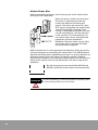
Important User Information
Solid state equipment has operational characteristics differing from those of
electromechanical equipment. Because of this difference, and also because of
the wide variety of uses for solid state equipment, all persons responsible for
applying this equipment must satisfy themselves that each intended application
of this equipment is acceptable.
In no event will RS Automation Co., Ltd. be responsible or liable for indirect
or consequential damages resulting from the use or application of this
equipment.
The examples and diagrams in this manual are included solely for illustrative
purposes. Because of the many variables and requirements associated with any
particular installation, RS Automation Co., Ltd. cannot assume responsibility
or liability for actual use based on the examples and diagrams.
No patent liability is assumed by RS Automation Co., Ltd. with respect to use
of information, circuits, equipment, or software described in this manual.
Reproduction of the contents of this manual, in whole or in part, without
written permission of RS Automation Co., Ltd. is prohibited.
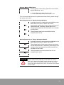
Throughout this manual, when necessary, we use notes to make you aware of
safety considerations.
WARNING
IMPORTANT
ATTENTION
WARNING
BURN HAZARD
Identifies information about practices or circumstances that can
cause an explosion in a hazardous environment, which may lead to
personal injury or death, property damage, or economic loss.
Identifies information that is critical for successful application and
understanding of the product.
Identifies information about practices or circumstances that can
lead to personal injury or death, property damage, or economic loss.
Attentions help you identify a hazard, avoid a hazard, and recognize
the consequence
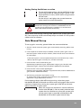
Labels may be located on or inside the equipment, for example, a
drive or motor, to alert people that dangerous voltage may be
present.
Labels may be located on or inside the equipment, for example, a
drive or motor, to alert people that surfaces may be at dangerous
temperatures.
Trademarks not belonging to RS Automation Co., Ltd. are property of their respective companies.
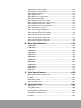
Contents
1. Introduction.............................................................. 11
Functionality ..................................................................................................11
Specifications ............................................................................................... 14
2. Installation ............................................................... 19
Servo Motor Installation ...............................................................................19
Servo Drive Installation ............................................................................... 22
Wiring............................................................................................................ 25
3. Operation.................................................................. 41
Overview ....................................................................................................... 41
Operator ........................................................................................................ 42
Mode ............................................................................................................. 44
Basic Set-up .................................................................................................. 54
4. Control ..................................................................... 57
Overview ....................................................................................................... 57
Position Control ............................................................................................ 60
Speed Control............................................................................................... 70
Torque Control.............................................................................................. 75
Multi-level Speed Control............................................................................ 79
Combination Control.................................................................................... 83
5. Tuning By Gain Adjustment ..................................... 85
Overview ....................................................................................................... 85
Gain Automatic Set-up ................................................................................ 87
Gain Manual Set-up ..................................................................................... 89
Torque Control Gain..................................................................................... 90
Speed Control Gain...................................................................................... 91
Position Control Gain ................................................................................... 92
Methods to Get Quick Responses ............................................................... 93
3
6. Application ............................................................. 101
Motor Stop...................................................................................................101
Motor Brake ................................................................................................ 103
Motor Revolving Direction......................................................................... 106
Regenerative Resistor ................................................................................ 107
Set-up for Smooth Operation.....................................................................112
Speed Limit.................................................................................................. 114
Position Feedback to the Controller. ..........................................................115
Analog Monitor ...........................................................................................117
Absolute Encoder ........................................................................................ 119
7. Troubleshooting ..................................................... 123
Check ........................................................................................................... 123
Servo Drive Failure..................................................................................... 124
A. Parameter .............................................................. 133
SEt-01 Speed Command Gain................................................................... 133
SEt-02 Speed Loop Proportional Gain ...................................................... 134
SEt-03 Speed Loop Integral Gain .............................................................. 135
SEt-04 Position Loop Proportional Gain ................................................... 135
SEt-05 External Torque Command Gain................................................... 135
SEt-06 Torque Command Filter ................................................................. 136
SEt-07 Position Feedforward Filter ........................................................... 137
SEt-08 DA Monitor Channel 1 Scale ......................................................... 137
SEt-09 DA Monitor Channel 2 Scale ......................................................... 138
SEt-10 Forward Internal Torque Limits ..................................................... 138
SEt-11 Reverse Internal Torque Limits ...................................................... 139
SEt-12 Forward External Torque Limits .................................................... 139
SEt-13 Reverse External Torque Limits..................................................... 139
SEt-14 Forward Emergency Stop Torque ................................................ 139
SEt-15 Reverse Emergency Stop Torque ................................................. 140
SEt-16 TG-ON Speed Level........................................................................ 140
SEt-17 Zero Clamp Level............................................................................ 141
SEt-18 In Speed/In Position Range............................................................ 142
SEt-19 Acceleration Time........................................................................... 142
SEt-20 Deceleration Time .......................................................................... 143
SEt-21 S-Curve Operation Time ................................................................ 143
SEt-22 Near Position Range....................................................................... 144
SEt-23 Encoder Output Ratio Numerator ................................................. 145
SEt-24 Encoder Output Ratio Denominator ............................................. 146
SEt-25 Jog Command Speed .................................................................... 146
SEt-26 Internal Speed Command 1........................................................... 147
SEt-27 Internal Speed Command 2........................................................... 148
SEt-28 Internal Speed Command 3........................................................... 148
SEt-29 Servo OFF Delay Time ................................................................... 148
SEt-30 Braking Application Speed After Servo OFF ................................ 149
SEt-31 Brake Active Delay Time After Servo OFF.................................... 150
4
SEt-32 Brake Inactive Delay Time After Servo ON .................................. 150
SEt-33 Following Error Level ..................................................................... 151
SEt-34 Position Feedforward Gain ............................................................ 151
SEt-35 Position Command Filter ............................................................... 151
SEt-36 Electronic Gear Ratio Numerator .................................................. 152
SEt-37 Electronic Gear Ratio Denominator .............................................. 153
SEt-38 Speed Bias ...................................................................................... 153
SEt-39 Speed Bias Application Range ...................................................... 153
SEt-40 Speed Command Filter .................................................................. 154
SEt-41 Control Mode Selection ................................................................. 154
SEt-42 System Gain ................................................................................... 155
SEt-43(1) Servo Enable Method ................................................................ 155
SEt-43(2) P-OT Signal Function Selection................................................. 156
SEt-43(3) N-OT Signal Function Selection................................................ 156
SEt-43(4) TG-ON Signal Function Selection............................................. 156
SEt-44(1) Dynamic Brake ........................................................................... 157
SEt-44(2) Dynamic Brake After the Motor Stopped................................. 158
SEt-44(3) Emergency Stop Method .......................................................... 158
SEt-44(4) Encoder Output Pulse Direction................................................ 159
SEt-45(1) Main Power Supply Type .......................................................... 159
SEt-45(2) Speed Command Offset Auto Adjustment .............................. 160
SEt-45(3) Speed Limit Method .................................................................. 160
SEt-45(4) Motor Revolving Direction ........................................................ 160
SEt-46(1) Position Command Pulse Type ................................................. 161
SEt-46(2) Speed Command Unit ............................................................... 162
SEt-46(3) Position Command Input Circuit Type ..................................... 162
SEt-46(4) Speed Observer Selection......................................................... 163
SEt-47 Notch Filter...................................................................................... 163
SEt-48 Password......................................................................................... 163
SEt-50 (1) Serial Encoder Type .................................................................. 164
SEt-50 (2) In/Output Signal Status Display............................................... 164
SEt-50 (3) Parameter Fixiation................................................................... 165
SEt-50 (4) Parameter Initialization Type.................................................... 165
SEt-51 Encoder Type .................................................................................. 166
SEt-52 Motor Type...................................................................................... 166
SEt-53 Motor Capacity ............................................................................... 167
SEt-54 Speed Integral Gain Auto Adjustment ......................................... 167
SEt-55 Torque-Command for Speed Integral Gain Auto Adjustment .... 168
SEt-56 Speed Command for Speed Integral Gain Auto Adjustment ..... 168
SEt-57 Position Error for Speed Integral Gain Auto Adjustment ........... 169
SEt-58 Auto Tuning Speed......................................................................... 169
SEt-59 Input Signal Assignment 1 ............................................................ 170
SEt-60 Input Signal Assignment 2 ............................................................ 171
SEt-61 Input Signal Assignment 3 ............................................................ 171
SEt-62 Input Signal Assignment 4 ............................................................ 171
SEt-63 Input Signal Assignment 5 ............................................................ 171
5
SEt-64 Forward Torque Offset ................................................................... 172
SEt-65 Reverse Torque Offset.................................................................... 172
SEt-66 Load Inertia Ratio ........................................................................... 172
SEt-67 Speed Limit..................................................................................... 173
SEt-68 Maximum Torque Used ................................................................. 173
SEt-69 System Bandwidth ......................................................................... 173
SEt-71 DA Monitor Channel 1 Offset .........................................................174
SEt-72 DA Monitor Channel 1 Output Gain...............................................174
SEt-73 DA Monitor Channel 2 Offset .........................................................174
SEt-74 Monitor Channel 2 Output Gain .....................................................174
SEt-75 Overload Curve Level..................................................................... 175
SEt-76 Output Signal Assignment 1 ......................................................... 175
SEt-77 Output Signal Assignment 2 ......................................................... 175
SEt-78 DA Monitor Channel Selection...................................................... 176
SEt-79 Internal Speed Command 4........................................................... 177
SEt-80 Internal Speed Command 5........................................................... 178
SEt-81 Internal Speed Command 6........................................................... 178
SEt-82 Internal Speed Command 7........................................................... 178
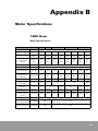
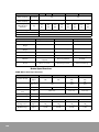
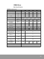
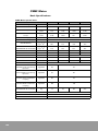
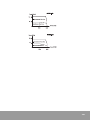
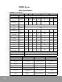
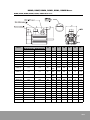
B. Motor Specifications.............................................. 179
CSMD Motor ............................................................................................... 179
CSMS Motor ............................................................................................... 183
CSMH Motor ............................................................................................... 187
CSMF Motor................................................................................................ 190
CSMK Motor ............................................................................................... 193
RSMD Motor ............................................................................................... 196
RSMS Motor ............................................................................................... 199
RSMH Motor ............................................................................................... 201
RSMF Motor................................................................................................ 204
RSMK Motor ............................................................................................... 207
RSML Motor................................................................................................ 210
RSMN Motor............................................................................................... 213
RSMX Motor ............................................................................................... 215
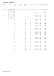
Motor Size ................................................................................................... 218
C. Cable Specifications .............................................. 225
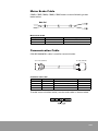
Motor 3-phase Power Supply Cable ......................................................... 225
Encoder Cable............................................................................................. 227
I/O Cable...................................................................................................... 229
Motor Brake Cable...................................................................................... 231
Communication Cable ............................................................................... 231
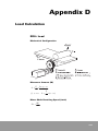
D. Load Calculation .................................................... 233
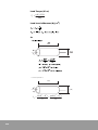
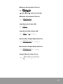
ROLL Load................................................................................................... 233
Timing Belt Load ........................................................................................ 236
Horizontal BALL SCREW Load................................................................... 238
Vertical BALL SCREW Load ....................................................................... 241
RACK & PINION Load................................................................................. 244
Disk Load..................................................................................................... 247
6
A brief introduction to the manual is in this preface.
The following contents are included in the preface.
• User of the manual
• Purpose of the manual
• Reference
• Symbols and Notations
User of the manual
This user’s manual explains the specifications, installation, wiring,
operation, abnormal status assessment and troubleshooting, and
maintenance of the CSDP Plus Servo Drive.
This manual is made for the engineers who want to install, wire, and
operate the CSDP Plus Servo Drive or apply the CSDP Plus Servo Drive
to a control system.
Those who do not have basic understanding of the CSDP Plus Servo
Drive need to receive the product education provided by the before
using the product.
The purpose of the manual
This manual explains the installation, configuration, operation,
malfunction assessment, troubleshooting measures, and maintenance
and repair of the CSDP Plus Servo Drive. The necessary wiring
diagram and other installation guidelines are provided.
Symbols and Notations
The following symbols and notations are used in this manual.
• Bullet points are used to provide multiple kinds of information.
They are not used for sequential procedures.
• Numbers are used to provide sequential procedures or hierarchical
information.
7
Safety Instructions
Please read this manual and the related documentation thoroughly
and familiarize yourself with product information, safety instructions
and other directions before installing, operating, performing
inspection and preventive maintenance. Make sure to follow the
directions correctly to ensure normal operation of the product and
your safety.
ATTENTION
• If this product is used in a situation that may cause
personal injury and/or significant product damage,
implement safe measures such as use of fault-safe
equipment.
• Do not use this product under any conditions exposed to
explosive gases. It may cause an explosion.
ATTENTION
• Make sure to use an external device when configuring the
protective circuit breakers for emergencies or interlock
circuits.
• Fasten the terminal screws tightly to ensure that the cable
connection is secure. Incorrect cable connection may cause
overheating and product malfunction.
• Operate and keep the product under the allowed conditions
directed in product specifications.
Otherwise it may cause overheating and product
malfunction.
• Do not disassemble or remodel the product.
Otherwise it may cause an electric shock or malfunction.
• Do not touch the terminals when the power is on.
Otherwise it may cause an electric shock.
8
1
Introduction
Functionality
CSDP Plus is an AC servo motor drive adopting a 32-bit DSP that
realizes high accuracy control. CSDP Plus supports standard
incremental encoder, simple incremental encoder, and absolute
encoder for the sake of convenient system design.
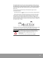
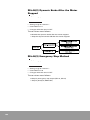
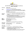
CSDP Plus-based servo system is usually configured as shown in the
following diagram. The controller in the diagram is PLC, but various
controllers can be used instead of PLC.
Servo System Configuration
11
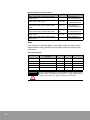
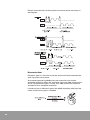
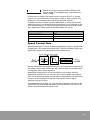
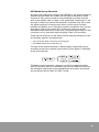
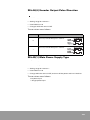
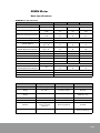
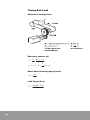
CSDP Plus has five different products. Basic specifications of the
products are displayed on the labels.
Servo Drive Label
Rated output of each product is described in the table below.
CSDP Plus Rated Output
Model Number
Rated Output
CSDP-15BX2
1.5 kW
CSDP-20BX2
2.0 kW
CSDP-30BX2
3.0 kW
CSDP-40BX2
4.0 kW
CSDP-50BX2
5.0 kW
Input Voltage B means 220V AC.
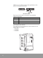
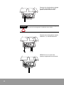
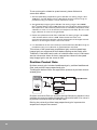
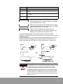
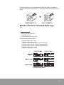
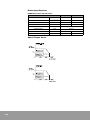
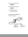
The models with the same appearance as that or the device in the
diagram below are as follows.
•
CSDP-15BX2
•
CSDP-20BX2
•
CSDP-30BX2
wv~ly
hshyt
z}yvu
z{h{|z
juZ
12
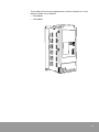
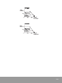
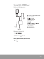
The models with the same appearance as that or the device in the
diagram below are as follows.
•
CSDP-40BX2
•
CSDP-50BX2
wv~ly
hshyt
z}yvu
z{h{|z
juZ
13
Specifications
Servo Drive
The specifications of CSDP Plus models are as follows.
CSDP Plus Model Specifications
CSDP-15BX2
CSDP-20BX2
Main Supply Voltage
(Vrms)
CSDP-30BX2
CSDP-40BX2
CSDP-50BX2
3-phase 200 to 230V, +10% to -15%, 50/60 Hz
Control Voltage (Vrms)
Rated Input Current
(Arms)
Single Phase 200 to 230V, +10% to -15%, 50/60 Hz
8.2
10.3
15.1
19.4
22.2
Input Power (kVA)
4.5
6
9
12
15
Output Voltage (Vrms)
200
200
200
200
200
Rated Output Current
(Arms)
10
13
19
25
28.5
Peak Output Current
(Arms)
30
39
57
75
85.5
Output Frequency
0 - 400 Hz
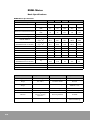
Performance specifications of CSDP Plus are as follows.
The performance specifications of CSDP Plus
Classification
Basic Specifications
Item
Control Method
PWM Control by IPM
Feedback Type
1000/2048/2500/6000/10000 Inc./Abs Type, 17 bit Serial Inc./
Abs type
Ambient Temperature/
Humidity in Operation
0 to 55°C/90% RH or less
Ambient Temperature/
Humidity in Storage
-25 to 80°C/90% RH or less
Mounting Type
1:5000
Load Fluctuation Rate
± 0.01% or less at the Rated Speed and within the Load Range
of 0 to 100%
0.1% or less at the Rated Speed and Ambient Temperature of
25°C
Speed Response
Frequency
400 Hz
Acceleration/
Deceleration Time
14
0% at the Rated Speed and Supply Voltage of 220V AC
Temperature
Fluctuation Rate
Torque Control
Accuracy
Position Control
Performance
Base Mounted Type
Speed Control Range
Voltage Fluctuation
Rate
Speed/Torque Control
Performance
Specifications
Feed forward
Positioning Completion
Range
± 2%
0 to 60 sec.
0 to 100%
0 to 250 pulse
The performance specifications of CSDP Plus
Classification
Item
Specifications
Command Pulse Type
Position Control
Command
Input Signal
Command Input Type
Pulse Frequency
Control Signal
Speed/Torque
Command Input
Signal
Multi-level Speed
Command Input
Signal
CW + CCW, Pulse Train+ Signal Train, A Phase+ BPhase
(90° phase difference)
Line drive - Voltage between levels 2.8 to 3.7 V
Open collector - External Voltage 24 V, 12 V, 5 V
Line drive - Maximum 900 kpps
Open collector - Maximum 250 kpps
Position Error Clear Input (Set at one of input terminals)
Command Voltage
Input Impedance
Circuit Time Constant
±10 V DC (14 bit A/D conversion)
Approx. 8.3 MΩ
35 µs or less
Revolving Direction
Used by assigning relevant functions to an input terminal
Speed Selection
Used by assigning relevant functions to an input terminal
Position Output Type
Input
I/O Signal
Output
Dynamic Brake
Regenerative Resistance
Line Drive Output: A, B, Z Phase, Absolute Encoder Data
Open Collector Output: Z phase
Servo On, Alarm Reset, Gain Group Shift, Forward/Reverse
Torque Limit, Forward/Reverse Revolution Prohibition, P/PI
Control Shift, Control Mode Shift, Internal Speed Command,
Zero Clamp, Position Command Pulse Inhibit, Absolute
Encoder Data Transmission
Position Completion, Near Postion, In Speed, Revolution
Detection, Torque Limit Detection, Speed Limit Detection,
Brake Control Output, Servo Warning Detection
When servo power supply is off, When alarm occurs, When
over-travel occurs (depending on conditions)
Embedded in Drive
Protection Function
Over current, Over voltage, Overload, Over speed, Low
Voltage, CPU Malfunction, Communication Malfunction, etc.
Monitoring
Position/Speed/Torque Command and Feedback, 2 Channel
D/A Output for measuring position error
Servo Motor
Motors supported by CSDP Plus are as follows.
CSDP Plus-supported motors
CSDP-15BX2
CSDP-20BX2
CSDP-30BX2
CSDP-40BX2
CSDP-50BX2
CSMD-15
CSMD-20
CSMD-25/30
CSMD-35/40
CSMD-45/50
CSMF-25
CSMF-35
CSMF-45
CSMH-40
CSMH-50
CSMF-15
CSMH-15
CSMH-20
CSMH-30
CSMK-12
CSMK-20
CSMK-30
CSMS-15
CSMS-20
CSMS-25/30
CSMS-35/40
CSMS-45/50
RSMD-15
RSMD-20
RSMD-25/30
RSMD-40
RSMD-45/50
RSMF-25
RSMF-35
RSMF-45
RSMH-40
RSMH-50
RSMF-15
CSMK-45/60
RSMH-15
RSMH-20
RSMH-30
RSMK-12
RSMK-20
RSMK-30
RSMK-45/60
RSML-12
RSML-20
RSML-30
RSML-45/60
RSMN-12
RSMN-20
RSMN-30
RSMS-15
RSMS-20
RSMS-25/30
RSMX-13
RSMX-20
RSMX-30
RSMS-35/40
RSMS-45/50
RSMX-45
15
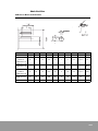
General specifications of all the motors are displayed on each label of
the motor.
Servo Motor Label
Rated Output is displayed as it is on servo drive.
Rated Output Display Method
Rated Output
16
13
1.3 kW
15
1.5 kW
20
2.0 kW
25
2.5 kW
30
3.0 kW
35
3.5 kW
40
4.0 kW
45
4.5 kW
50
5.0 kW
60
6.0 kW
Input Voltage B stands for 220V AC.
Definitions of the remaining numbers are as follows.
Servo Motor Label Number
Item
Input Voltage
Motor Shaft Key
Option
Motor Shaft
No.
Specifications
A
110V AC
B
220V AC
C
24V DC
D
110/220V AC
A
Key Present
B
Key Absent
N
Option Absent
B
Brake Present
S
Oil Seal Present
T
Brake and Oil Seal Present
1
Circular Type (Coupling Tightening)
3
Key Tightening Type
4
Taper Tightening Type
Encoder
CSDP Plus-supported encoders are as follows.
CSDP Plus-supported Encoders
Motor
CSMD, CSMF, CSMH, CSMK, CSMS
RSMD, RSMF, RSMH, RSMK, RSML,
RSMN, RSMS, RSMX
Mode
Encoder Type
A
2500 P/R
11-wire type Inc.
B
2500 P/R
15-wire type Inc.
D
1000 P/R
15-wire type Inc.
H
2048 P/R
Compact Abs.
M
10000 P/R
15-wire type Inc.
A
2500 P/R
9-wire type Inc.
K
5000 P/R
15-wire type Inc.
L
6000 P/R
15-wire type Inc.
M
10000 P/R
15-wire type Inc.
Compact Abs.
H
2048 P/R
Q
17 Bit Serial Abs.
R
17 Bit Serial Inc.
17
18
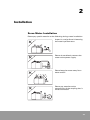
2
Installation
Servo Motor Installation
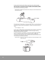
Please pay special attention to the following during motor installation.
Impact is a major factor in lowering
the motor’s performance.
Please do not directly connect the
motor to the power supply.
Please keep the motor away from
water and oil.
Please pay attention to the
concentricity of the coupling that is
linked to the load.
19
Please do not put stress on the
electric wires.
Please mount the motor vertically
or horizontally.
The shaft is oiled for corrosion
prevention. Please remove it before
installation.
Please connect the grounding line
to the grounding connection
terminal of the drive.
Coupling Assembly
Excessive impact during
coupling assembly can
damage the encoder.
Please measure the concentricity of the motor shaft and load shaft
after coupling assembly. Take four measurements by rotating each 90°
and adjust the difference between the maximum value and the
minimum value to be 0.03 mm or less.
20
Load Connection
If the center of the shaft
does not match, it will lower
the performance.
Allowed Load for Motor Shaft
Please make sure the load
on the motor shaft doesn’t
exceed load allowance.
Please refer to the motor
specifications in the
appendix for the allowed
load for each motor.
Motor Installation Environment
Motor Installation Specifications
Item
Storage Temperature
Condition
-20 to 80°C
Operating Temperature
0 to 55°C
Operating Humidity
RH 90% or less, non-condensing.
Installation environment needs to meet the following conditions.
•
Indoors.
•
Good Ventilation.
•
Easy to check and clean.
•
No explosive gas.
21
Servo Drive Installation
Please check the following before installing CSDP Plus.
•
Does the delivered product match the order?
•
Does the servo motor match the specifications of the servo drive?
•
Is the product broken?
•
Does the product have any loosened or cracked parts?
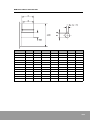
The installation environment required for CSDP Plus is as below.
CSDP Plus Installation Specifications
Item
Condition
Storage Temperature
-20 to 80° C
Operating Temperature
0 to 55° C
Operating Humidity
RH 90% or less, non-condensing
Vibration
0.5g (4.9 m/S2) or less
The installation environment needs to meet the following conditions.
22
•
Indoors
•
Good ventilation
•
Easy to check
•
No explosive gas.
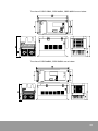
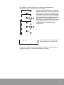
The sizes of CSDP-15BX2, CSDP-20BX2, CSDP-30BX2 are as below.
The sizes of CSDP-40BX2, CSDP-50BX2 are as below.
23
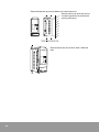
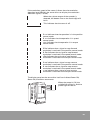
Please follow the command below to install the drive.
Please make sure that the drive is
installed vertically for enhanced
cooling efficiency.
Please attach the servo drive with a M5xL10
bolt.
wv~ly
hshyt
z}yvu
z{h{|z
juZ
24
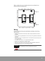
When multiple drives are installed, please set up cooling fans to
prevent excessive temperatures.
Wiring
Please follow the wiring command below according to the wiring
specifications.
•
Please install line filer, servo drive, motor, and input device as close as
possible.
•
Please attach surge-absorption circuit to relay, wiring breaker, and electric
contacter.
•
Please do not wire unused terminals. If unused terminals are wired, noise
can be generated.
•
If a cable should move, use a separate flexible cable.
•
Please use a noise filter at a power supply.
•
Signal line should be at least 30 cm away from the power supply line.
•
All the grounding terminals should be grounded.
WARNING
Signal line should be wired separately from the power supply
line. Otherwise, noise or system error can occur.
25
Wiring Specifications
Item
Specifications
Signal line
Multi core, twisted pair, batch shielded cable as thick as
AWG26 or more
Grounding Line
One-point grounding (100 Ω or less) with an electric wire as
thick as 3.5 mm2 or more
Input Power Cable Length
Max. 3 m
Encoder Cable Length
Max. 20 m
Motor Power Cable
Length
Max. 20 m
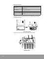
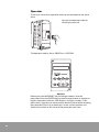
Connection terminal and connector are inside the cover. The cover is at
the lower end of the servo drive. Please pull it downward and draw it
up to open the cover.
juZ
juZ
juX
juY
Servo Drive Cover
The letters on the cover represent the terminal number.
Terminal block
26
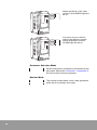
Power Supply Connection
Terminal block
Notation
Function
CN1
Cable Connection with Controller
CN2
Encoder Cable Connection
R
3-Phase 220V AC Main Power Supply Input Connection
S
3-Phase 220V AC Main Power Supply Input Connection
T
3-Phase 220V AC Main Power Supply Input Connection
P
Regenerative Resistance Connection (Regenerative Resistance Embedded)
B
Regenerative Resistance Connection (Regenerative Resistance Embedded)
U
Motor Power Cable Connection
V
Motor Power Cable Connection
W
Motor Power Cable Connection
r
Single-Phase 220V AC Circuit Power Supply Input Connection
s
Single-Phase 220V AC Circuit Power Supply Input Connection
Grounding Connection
Connect the 3-phase voltage to
R, S, and T terminals to supply
power to the main system.
27
CN1
CN2
Connect the single-phase voltage
to r and s terminals to supply
power to the control circuit.
r s
WARNING
Previous CSDP users need to be careful with the wiring since
the terminal arrangement is different from CSDP.
Connect the motor power supply
cable to U, V, and W terminals.
CSDP Plus has its own lowcapacity regenerative resistance.
juX
juY
w i
28
WARNING
If an extra high-capacity regenerative resistance is needed,
please remove the internal wiring of P and B terminals and
connect the external regenerative resistance.
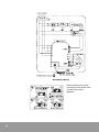
Power Supply Wiring
In the diagram above, MCCB stands for Molded Case Circuit Breaker
and MC stands for Magnetic Conductor.
Please use a push-button switch that transmits electricity only when it
is pushed at c in the circuit. Please connect the relay at d when the
power needs to be shut down. Please attach a surge suppressor to the
magnetic switch relay coil at e.
29
Connection with Controller
Connect the cable of controller to
the CN1 connector.
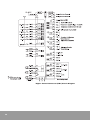
CN1
CN2
Controller Connector (CN1) Pin
30
No.
Symbols
Wire Color
Usage
1
+24V IN
Red
External 24V Input
2
+24V IN
Yellow
External 24V Input
3
DI#1
Sky-blue
Input Signal Assignment (Default Value/SV-ON)
4
DI#2
White
Input Signal Assignment (Default Value/P-OT)
5
DI#3
Pink
Input Signal Assignment (Default Value/N-OT)
6
DI#4
Orange
Input Signal Assignment (Default Value/P-CON)
7
DI#5
Gray
Input Signal Assignment (Default Value/A-RST)
8
DI#6
Red 1 Dot
Input Signal Assignment (Default Value/N-TL)
9
DI#7
Yellow 1 Dot
Input Signal Assignment (Default Value/P-TL)
10
DI#8
Sky-blue 1 Dot
Input Signal Assignment (Default Value/ESTOP)
11
PULS+
White 1 Dot
Position Command Signal
12
PULS-
Pink 1 Dot
Position Command Signal
13
SIGN+
Orange 1 Dot
Position Command Signal
14
SIGN-
Gray 1 Dot
Position Command Signal
17
Z-PULSE+
Sky-blue 2 Dots
Encoder Z-PULSE Output
18
Z-PULSE-
White 2 Dots
Encoder Z-PULSE Output
19
V-REF
Pink 2 Dots
Analog Speed Command Signal
20
V-REF SG
Orange 2 Dots
Analog Speed Command Signal
Gray 2 Dots
Analog
Analog Torque Command Signal
21
T-REF
22
T-REF SG
Red 3 Dots Analog
Analog Torque Command Signal
23
AM-CH2
Yellow 3 Dots
Analog Monitor Channel 2
24
-
Sky-blue 3 Dots
-
25
BAT-
26
-
White 3 Dots
Absolute Encoder Battery GND
Pink 3 Dots
-
Controller Connector (CN1) Pin
No.
Symbols
Wire Color
Usage
27
AM-SG
Orange 3 Dots
Analog Monitor Output GND
28
AM-CH1
Gray 3 Dots
Analog Monitor Channel 1
29
EA+
Red 4 Dots
Encoder Signal (Line Drive) Output A
30
EA-
Yellow 4 Dots
Encoder Signal (Line Drive) Output/A
31
EB+
Sky-blue 4 Dots
Encoder Signal (Line Drive) Output B
32
EB-
White 4 Dots
Encoder Signal (Line Drive) Output/B
33
EC+
Pink 4 Dots
Encoder Signal (Line Drive) Output C
34
EC-
Orange 4 Dots
Encoder Signal (Line Drive) Output/C
35
PS+
Gray 4 Dots
Encoder Signal (Line Drive) Output
36
PS-
Red/Twisted Pair
Wire
Encoder Signal (Line Drive) Output
37
AL1
Yellow/Twisted
Pair Wire
Alarm Code 1 (Open Collector) Output
38
AL2
Sky-blue/Twisted
Pair Wire
Alarm Code 2 (Open Collector) Output
39
AL3
White/Twisted Pair
Wire
Alarm Code 3 (Open Collector) Output
40
AL-SG
Pink/Twisted Pair
Wire
Alarm Code Output GND
41
DO#1+
Orange/Twisted
Pair Wire
Output Signal Assignment (Default Value/
P-COM)
42
DO#1-
Gray/Twisted Pair
Wire
Output Signal Assignment (Default Value/
P-COM)
43
DO#2+
Red/1 Line
Output Signal Assignment (Default Value/
TG-ON)
44
DO#2-
Yellow/1 Line
Output Signal Assignment (Default Value/
TG-ON)
45
SALM+
Sky-blue/1 Line
Servo Alarm Output
46
SALM-
White/1 Line
Servo Alarm Output
47
DO#3+
Pink/1 Line
Output Signal Assignment (Default Value/BK)
48
DO#3-
Orange/1 Line
Output Signal Assignment (Default Value/BK)
49
BAT+
Gray/1 Line
Absolute Encoder Battery Power Supply
31
Higher Control Connector (CN1) Circuit Diagram
32
Encoder Connection
Connect the encoder cable to CN2
connector.
CN1
CN2
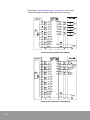
Encoder Connector (CN2) Pin
No.
Function
9-wire
Inc.
11-wire
Inc.
15-wire
Inc.
Compact
Abs.
Serial
Abs.
Serial
Inc.
1
EO [V]
G
G
G
G
G
G
3
A
A
A
A
A
4
A
B
B
B
B
5
B
C
C
C
C
6
B
D
D
D
D
7
C
E
E
E
E
8
C
F
F
F
F
P
K
K
K
K
L
L
L
2
9
10
U/SD+
11
RST (Abs)
R
12
13
/U/SD-
14
V
M
15
V
N
16
W
P
17
W
R
18
BAT+
T
T
19
BAT-
S
S
20
E5 [V]
FG
R
L
H
H
H
H
H
H
J
J
J
J
J
J
33
Please See "Cable Specifications" in Appendix C for further
information about encoder cable, connector, and plug.
11-wire Incremental Encoder Wiring
15-wire Incremental Encoder Wiring
34
Compact Absolute Encoder Wiring
Serial Encoder Wiring
35
Encoder Connector Specifications
Motor
Types
Products
RSMD, RSMF, RSMH, RSMK, RSML, RSMN,
RSMS, RSMX
9-wire Inc.
DMS3108B20-29S
(or DMS3106B20-29S)
CSMD, CSMF, CSMH, CSMS
11-wire Inc.
DMS3108B20-29S
(or DMS3106B20-29S)
CSMD, CSMF, CSMH, CSMS, CSMK, RSMD,
RSMF, RSMH, RSMK, RSML, RSMN, RSMS,
RSMX
15-wire Inc.
DMS3108B20-29S
(or DMS3106B20-29S)
CSMD, CSMF, CSMH, CSMS, RSMD, RSMF,
RSMH, RSMK, RSML, RSMN, RSMS, RSMX
Compact
Abs.
DMS3108B20-29S
(or DMS3106B20-29S)
RSMD, RSMF, RSMH, RSMK, RSML, RSMN,
RSMS, RSMX
Serial Abs
DMS3108B20-29S
(or DMS3106B20-29S)
RSMD, RSMF, RSMH, RSMK, RSML, RSMN,
RSMS, RSMX
Serial Inc.
DMS3108B20-29S
(or DMS3106B20-29S)
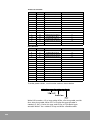
Fuse
Fuse capacity in the table below is the figure when the load is 100%.
Please select a wiring breaker or fuse capacity after considering the
load factor.
Fuse Specifications
Input Power Supply
Capacity
NFB
Inrush current
CSDP-15BX2
4.6 kVA
16 A
30 A
50 A
CSDP-20BX2
6.1 kVA
21 A
30 A
50 A
CSDP-30BX2
9.1 kVA
31 A
40 A
50 A
CSDP-40BX2
12.1 kVA
41 A
50 A
50 A
CSDP-50BX2
15.2 kVA
52 A
60 A
50 A
ATTENTION
36
Fuse
Using a high-speed fuse is not possible. As the power supply
of the drive is a condenser input type, if a high-speed fuse is
used, it can blow even under normal circumstances.
Anti-noise Measures
As CSDP Plus uses a high-speed switching device and microprocessor
in its main circuit, it can be affected by the switching noise from the
switching device depending on the methods of peripheral wiring and
grounding.
ATTENTION
Please use a thick line with the diameter 3.5 mm2 or above for
grounding. And, make sure that the signal line and the power
supply line are separated.
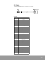
Noise Filter (3 phase AC)
3 Phase 220V AC Noise Filter
Servo Drive
Recommended Noise Filter
CSDP-15B
X
[
Y
\
Z
]
CSDP-20 - 30B
CSDP-40 - 50B
n
Mode
Specification
NFZ-4030SG
250V/15A
NFZ-4030SG
250V/30A
NFZ-4040SG
250V/40A
37
Grounding, Wiring
Please separate the input
and output wires of the filter,
and do not tie them
together.
38
Please position the
grounding line of the noise
filter away from the output
wiring and do not tie it with
other signal lines in the
same duct.
Connect the grounding line
of the noise filter to the
grounding frame separately.
Please do not connect the
grounding line of the noise
filter to other grounding
lines.
If the noise filter is inside the
case, connect the grounding
line of the noise filter and all
other grounding lines of
different devices to the
grounding frame and finish
the grounding.
39
40
3
Operation
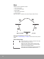
Overview
You can instantly use general electronic appliances like a television by
just turning it on. But turning on a servo drive is not enough to operate
a servo motor. To properly operate a servo drive, a servo-ON signal
from a controller is required.
If the power supply is engaged
but servo-ON signal is not
issued, the servo drive and the
motor are separated.
When the controller issues a
servo-ON signal, the drive
transmits voltage to the motor.
If the command for operating
the motor is approved, then the
drive can operate the motor
according to the command.
41
Operator
To set up a servo drive, operator needs to be connected to the servo
drive.
Connect the operator cable to
CN3 (9 pin) terminal.
The operator used by for to CSDP Plus is CST-SD2.
Operator
Please press the MODE/SET key to change mode or save the
parameter. Press the ENTER key to select the parameter or escape to
higher mode after selection. LED displays six digit numbers. Then
press left or right keys to move to other decimal places while selecting
the parameter. Press up or down keys at the current position and
search the number or the value of the parameter you want.
42
For instance, if you want to set up a position regulator loop
proportional gain, follow the command below.
Please press the MODE key until SEt-01
appears. When you see SEt-01, press the
direction keys until you see Set-04, the
parameter for the position regulator loop
proportional gain. Then press the ENTER
key and the position proportional gain
parameter will be displayed. Press the
direction keys to get the value you want
and press the SET key to save it. Press
the ENTER key to escape from the
current level.
No. 1 digit is on the far right and
the No. 6 digit is on the far left.
ྞ
ྜྷ
ྜ
ྛ
ྚ
ྙ
In the status display mode and parameter selection mode, a decimal
place sometimes has a separate meaning of its own.
43
Mode
CSDP Plus has five operation modes.
•
Status Display Mode
•
Parameter Selection Mode
•
Monitor Mode
•
Alarm History Search Mode
•
Operation Mode
When the power is turned on, the status display mode will start.
Please press the MODE key to change mode.
Please See "Troubleshooting" in Chapter 7 for the alarm history search
mode.
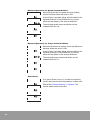
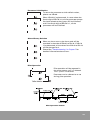
Status Display Mode
When the power is turned on, the dot on the right
side of the fifth digit will be lit.
When the motor speed reaches the level of the
speed command, the top line on the fourth digit
will be lit as the diagram shows.
When the revolution detection signal is displayed,
the middle line on the fourth digit will be lit.
44
If the revolution speed of the motor is faster than the revolution
detection level (SEt-16), the servo drive can display the revolution
detection signal (/TG-ON).
When the z-phase output of the encoder is
detected, the bottom line on the fourth digit will
be lit.
This indicates that the servo is off.
P. run indicates that the operation is in the position
control mode.
S. run indicates that the operation is in speed
control mode.
t.run indicates that the operation is in torque
control mode.
P. Pot indicates that a signal to stop forward
revolution is received in the position control mode.
S. Pot indicates that a signal to stop forward
revolution is received in the speed control mode.
t.Pot indicates that a signal to stop forward
revolution is received in the torque control mode.
P. not indicates that a signal to stop reverse
revolution is received in the position control mode.
S. not indicates that a signal to stop reverse
revolution is received in the speed control mode.
t. not indicates that a signal to stop reverse
revolution is received in the torque control mode.
The display panel on the servo drive itself can indicate Power ON,
Servo ON, and Alarm occurrence.
POWER
POWER
ALARM
ALARM
SVRON
STATUS
When the power is ON, the
middle line will be lit. And the
power light will be on.
SVRON
CN3
45
wv~ly
wv~ly
hshyt
hshyt
z}yvu
z{h{|z
When the Servo is ON, a dot
will be lit. And SVRON light will
be on.
z}yvu
juZ
wv~ly
wv~ly
hshyt
hshyt
z}yvu
z{h{|z
z}yvu
If an alarm occurs, the first
digit of the relevant number
will be displayed. And the
ALARM light will be on.
juZ
Parameter Selection Mode
Various operational conditions are allocated to the
parameter. Please See "Parameter" in Appendix A
for the functions of each parameter.
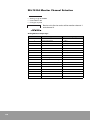
Monitor Mode
The monitor mode shows various data generated
while the drive controls the motor.
46
Monitor Number List
No.
Con-01
Contents (Unit)
Speed Feedback (RPM)
Con-02
Speed Command (RPM)
Con-03
Torque Command (%)
Con-04
Electrical Angle (°)
Con-05
Speed Error (RPM)
Con-06
Position Error (pulse)
Con-07
Mechanical Angle (°)
Con-08
Position Feedback (pulse)
Con-09
Position Command (pulse)
Con-10
Offset of Analog Speed Command
Con-11
Offset of Analog Torque Command
Con-12
In/Output Signal Status
Con-13
Load Inertia Ratio
Con-16
Frequency of the Position Command pulse (kHz)
Con-17
Analog Speed Input Voltage (10 mV)
Con-18
Analog Torque Input Voltage (10 mV)
Con-19
Maximum Torque Used Until Now
Con-20
Multi-revolution Position of the Absolute Encoder
Con-21
Maximum Position Error (pulse)
Con-22
Maximum Speed (RPM)
Con-23
Encoder Pulse Value After Servo ON
Con-24
One Revolution Position of the Absolute Encoder
Con-29
DC Voltage [V]
Con-30
Instant Output Power [W]
Con-32
Servo Drive Usage Rate [%]
47
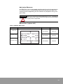
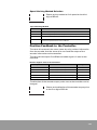
Con-12 Function
The in/output signal status display method can be set up on the
second digit of SEt-50. To use the previous CSDP method for existing
CSDP users, please set the parameter to 1. To use the original CSDP
Plus display method, please set the parameter to 0.
When the second digit of SEt-50 is 0, the in/output signal status of Con12 will be displayed as below.
When it is 1, the status will be displayed as below.
Operation Mode
Operation Number List
No.
48
Event
USr-01
Jog Operation
USr-02
Auto Tuning
USr-03
Auto Adjustment for Speed Command Offset/Adjustment for Current Offset
USr-04
Auto Adjustment for Torque Command Offset
USr-05
Manual Adjustment for Speed Command Offset
USr-06
Manual Adjustment for Torque Command Offset
USr-07
Alarm Reset
USr-09
Parameter Initialization
USr-10
Alarm History Initialization
USr-90
Pilot Operation
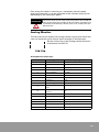
Jog Operation
The revolution will continue in the forward
direction (counterclockwise) only while the
up button is pushed, and in the reverse
direction (clockwise) only while the down
button is pushed.
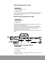
Auto Tuning
The gain of the servo drive is usually in proportion to inertia. If velocity
speed regulator loop proportional gain and velocity speed regulator
loop integral gain are not set properly, the operation characteristics of
the servo drive can slow down.
The order of auto tuning is as follows.
Auto Tuning Order
49
Please set SEt-69 by referring to the table below.
Set-69 Set Up
System Rigidity
SEt-69
Low Rigidity
20
Medium Rigidity
30
High Rigidity
45
During the process of auto tuning, the following
parameter will be automatically set.
• Speed Loop Proportional Gain (SEt-02)
• Speed Loop Integral Gain (SEt-03)
• Position Loop Proportional Gain (SEt-04)
• Torque Command Filter (SEt-06)
• Speed Command Filter (SEt-40)
• System Gain (SEt-42)
• Inertia Ratio (SEt-66)
If auto tuning doesn’t work well, please adjust the gain according to
the command below.
1. First, set the speed integral gain (SEt-03) to its default value.
2. Raise the speed proportional gain (SEt-02) to the range that doesn’t cause
vibration in the system.
3. Raise the speed integral gain (SEt-03) to the range that doesn’t cause
vibration in the system.
4. Try jog operation or pilot operation.
5. If there is a serious vibration or noise, please reduce the speed
proportional (SEt-02) or speed integral gain (SEt-03).
Please repeat the fourth and fifth steps until stabilization.
Quick response cannot be expected when the inertia of the load
exceeds five times the inertia of the motor’s rotor or when the load
torque is higher than the motor torque. In these cases, please follow
the command below for adjustment.
50
•
Reduce the inertia of the system and load torque.
•
Extend the time for acceleration and deceleration.
•
Replace the motor with another one with higher rotor inertia.
•
Use a motor with higher output torque.
•
Lower the gain to reduce the response of the system.
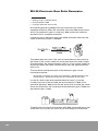
Current Offset Adjustment
To adjust the current offset, please set the second
digit of SEt-45 to 1 or 2.
1: Current Adjustment when Servo is OFF
2: Current Offset Adjustment when Servo is ON
To run the auto adjustment for speed command offset, please change
the preset value to 0.
Auto Adjustment for Speed Command Offset
Auto adjustment for speed command offset can be
done when the servo is either ON or OFF.
The voltage input of the current speed command is
identified as 0V. Therefore, please adjust the
voltage generated from the controller or a variable
resistor to 0V.
The adjusted speed command offset can be
checked with Con-10.
Auto Adjustment for Torque Command Offset
Auto adjustment for torque command offset can be
done when the servo is either ON or OFF.
The voltage input of the current torque command
will be identified as 0V. Therefore, please adjust the
voltage output generated from the controller or a
variable resistor to 0V.
The adjusted torque command offset can be
checked with Con-11.
ATTENTION
Afterthought speed command offset or torque command
offset is automatically adjusted, so themotor can move a
little. This is because the power supply voltage has noise or
fluctuates a little. To completely stop the motor by analog
command, please operate the system in the zero clamp speed
control mode.
51
Manual Adjustment for Speed Command Offset
Manual adjustment for speed command offset
should be done when the servo is ON.
If the UP key is pushed, offset will be added in the
forward direction. If the DOWN key is pushed,
offset will be added in the reverse direction.
The adjusted speed command offset can be
checked with Con-10.
Manual Adjustment for Torque Command Offset
Manual adjustment for torque command offset can
be done when the servo is ON.
If the UP key is pushed, offset will be added in the
forward direction. If the DOWN key is pushed,
offset will be added in the reverse direction.
The adjusted torque command offset can be
checked with Con-11.
Alarm Reset
If an alarm (Error) occurs, it can be turned off by
Usr-07 after the cause of the problem is dealt with.
Please See"Troubleshooting" in Chapter 7 for
further details about the alarm.
52
Parameter Initialization
To return the parameter to their default values,
please use USr-09.
When USr-09 is implemented, in cases where the
fourth digit of SEt-50 is 0, all the parameter except
for those related to the system will be initialized
and if the fourth digit of SEt-50 is 1, all the
parameter will be initialized.
Alarm History Deletion
When an alarm occurs, the alarm code will be
recorded in the order of PAr-01 to PAr-10. If USr-10
is implemented, all the values from PAr-01 to PAr-10
will be changed to 0.
Please See "Troubleshooting" in Chapter 7 for
detailed information about alarm.
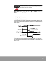
Pilot Operation
Pilot operation will be repeated in
the same pattern until it is aborted.
The 1 cycle is 14 seconds.
Parameter can be referred to or set
during pilot operation.
Pilot Operation Pattern
53
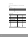
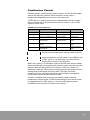
Basic Set-up
There are basic parameter that should be set first before setting other
parameter.
The parameter included in the basic set-up are listed in the table
below.
Basic Parameter
Basic Parameter
Event
SEt-41
Control Mode
SEt-51
Encoder Type
SEt-52
Motor Type
SEt-53
Motor Capacity
Please turn off the power after basic set-up and then restart it.
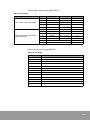
Please set up the control mode at SEt-41.
SEt-41 Set-up Value
Setting
54
Control Mode
0
Position Mode
1
Speed Mode
10
Direction Change Speed Mode
12
Torque Limit Speed Mode
/C-SEL OFF
/C-SEL ON
5
Zero Clamp Mode
2
Torque Mode
3
Multi-level Speed Mode
9
Speed Limit Torque Mode
Speed Limit Torque
Mode
Torque Mode
6
Torque + Speed Mode
Torque Mode
Speed Mode
7
Position + Torque Mode
Position Mode
Torque Mode
8
Position + Speed Mode
Position Mode
Speed Mode
13
Position + Multi-level Speed
Mode
Position Mode
Multi-level Speed
Mode
14
Speed + Multi-level Speed Mode
Speed Mode
Multi-level Speed
Mode
15
Torque + Multi-level Speed Mode Torque Mode
Multi-level Speed
Mode
Please select the encoder type at SEt-51.
SEt-51 Set-up Value
Motor
Mode
CSMD, CSMF, CSMH, CSMK, CSMS
RSMD, RSMF, RSMH, RSMK, RSML,
RSMN,RSMS,RSMX
Encoder Type
Set-up(SEt-51)
A
2500 P/R
Inc. (11-wire)
100
B
2500 P/R
Inc. (15-wire)
101
D
1000 P/R
Inc. (15-wire)
102
H
2048 P/R
Compact Abs.
104
M
10000 P/R
Inc. (15-wire)
106
A
2500 P/R
Inc. (9 -wire)
107
K
5000 P/R
Inc. (15 -wire)
103
L
6000 P/R
Inc. (15 -wire)
105
M
10000 P/R
Inc. (15 -wire)
106
H
2048 P/R
Compact Abs.
104
Q
17 Bit Serial Abs.
108
R
17 Bit Serial Inc.
109
Please set the motor type at SEt-52.
SEt-52 Set-up Value
Motor
Set-up Value
CSMS
2222
CSMD
2312
CSMH
2322
CSMF
2332
CSMK
2342
RSMS
2402
RSMD
2412
RSMH
2422
RSMF
2432
RSMK
2442
RSML
2452
RSMN
2462
RSMX
2472
55
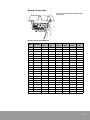
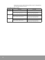
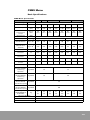
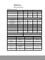
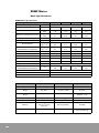
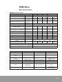
Please set the motor capacity at SEt-53.
SEt-53 Set-up Value
56
1.2kW
1.3kW
1.5kW
2.0kW
2.5kW
3.0kW
3.5kW
4.0kW
4.5kW
5.0kW
6.0kW
CSMD
-
-
150
200
250
300
350
400
450
500
-
CSMF
-
-
150
-
250
-
350
-
450
-
-
CSMH
-
-
150
200
-
300
-
400
-
500
-
CSMK
120
-
-
200
-
300
-
-
450
-
600
CSMS
-
-
150
200
250
300
350
400
450
500
-
RSMD
-
-
150
200
250
300
350
400
450
500
-
RSMF
-
-
150
-
250
-
350
-
450
-
-
RSMH
-
-
150
200
-
300
-
400
-
500
-
RSMK
120
-
-
200
-
300
-
-
450
-
600
RSML
120
-
-
200
-
300
-
-
450
-
600
RSMN
120
-
-
200
-
300
RSMS
-
-
150
200
250
300
350
400
450
500
-
RSMX
-
130
-
180
-
290
-
-
440
-
-
4
Control
Overview
Input signal is sent to servo drive from the controller, while the output
is vice versa.
IMPORTANT
Only A contact is used for CSDP Plus except for P-OT and
N-OT. Therefore, ON means connection and OFF means
interruption, excluding the cases of P-OT and N-OT. For
example, when /C-DIR signal is ON, the terminal where /C-DIR
signal is allocated will be connected and the electric current
will flow, but when /C-DIR signal is OFF, the terminal will be
interrupted so that the electricity will be shut off.
Input Signal
There are 20 different input signals. The functions of the signals are
shown below.
Input Signal
Signal
Function
Application Control Mode
/SV-ON
Control Voltage for the servo motor.
All
/A-RST
Clear the servo alarm.
All
/G-SEL
Shifts the gains of the two groups.
All
/P-TL
Limits the forward torque within the preset value (SEt-12).
All
/N-TL
Limits the reverse torque within the preset value (SEt-13).
All
P-OT
Stops the forward movement of the load devices when they reach the
mobility limit in the forward direction.
All
N-OT
Stops the reverse movement of the load when they reach the mobility
limit in the reverse direction.
All
Position, Speed, Multi-level
Control
/P-CON
Changes the speed control method from PI control to P control.
/C-SEL
Changes the control mode from the combination control.
/C-DIR
Determines the revolution direction of the motor in the multi-level
speed control.
Multi-level Control
/C-SP1
Selects the revolution speed in the multi-level speed control.
Multi-level Control
/C-SP2
Selects the revolution speed in the multi-level speed control.
Multi-level Control
/C-SP3
Selects the revolution speed in the multi-level speed control.
Multi-level Control
Complex Control
57
Input Signal
Signal
Function
Application Control Mode
/Z-CLP
Ignores the input value if the value of analog command is lower than
the speed zero clamp level (SEt-17) in the speed control.
analog command Speed
Control
/INHIB
Ignores the position command pulse input.
/ABS-DT
Position Control
Sends absolute value data to the controller through EA, EB signals.
All
/A-TL
Limits the torque in the torque speed limit control mode through
torque command.
/P-LCR
Clear the current position and position command.
/EMG
Issues an emergency alarm.
All
Resets the multi-revolution of the absolute encoder and the alarm.
All
/R-ENC
Torque Speed Limit Control
Position Control
Output Signal
There are eight different output signals. The functions of the signals
are shown below.
Output Signal
Signal
Function
Application Control Mode
/P-COM
This signal will be displayed if the position error is within the range of
position completion decision (SEt-18).
Position Control
/NEAR
This signal will be displayed if the position error is within the range of
near position proximity decision (SEt-23).
Position Control
/V-COM
This signal will be displayed if the error between the speed command
and the revolution speed of the motor is within the range of in speed
(SEt-18).
Multi-level Control
/TG-ON
This signal will be displayed if the motor revolves at the revolution
detection level value (SEt-17) or above.
All
/T-LMT
This signal will be displayed if the torque reaches the torque limit
value.
All
/V-LMT
This signal will be displayed if the speed reaches the speed limit
value.
All
Activates the brake of the servo motor.
All
This signal will be displayed when a servo warning is detected.
All
/BK
/WARN
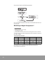
Signal Assignment
The input signals should be allocated to the CN1 connector’s input
pins from DI#1 to DI#8.
Input Signal Assignment Table
58
Parameter
Fourth Digit
Third Digit
Second Digit
First Digit
SEt-59
/P-CON
SEt-60
/C-SEL
N-OT
P-OT
/SV-ON
/P-TL
/N-TL
/A-RST
SEt-61
SEt-62
/C-SP3
/C-SP2
/C-SP1
/C-DIR
/A-TL
/G-SEL
/INHIB
/Z-CLP
SEt-63
/P-CLR
/R-ENC
/EMG
/ABS-DT
For instance, put 7 in the fourth digit of SEt-59 to allocate the/P-CON
signal to the DI#7 pin.
Put 3 in the second digit of SEt-62 to allocate the /INHIB signal to DI#3
pin.
When 9 is set, it is always valid and when 0 is set, it is always invalid.
For instance, to keep SV-ON always valid when the power is on
regardless of the wiring, put 9 in the first digit of SEt-59.
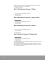
Output Signal Assignment Table
Parameter
Fourth digit
Third digit
Second digit
First digit
SEt-76
SEt-77
/V-COM
/BK
/TG-ON
/P-COM
/WARN
/NEAR
/V-LMT
/T-LMT
Put 1 in the first digit of SEt-76 to allocate /P-COM signal to the DO#1
pin.
Put 3 in the fourth digit of SEt-77 to use /WARN function through DO#3
pin.
Setting 0 makes the system always invalid and there is no value to
make the system always valid, which is different from the input case.
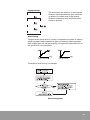
If the warning in the diagram is displayed, it means
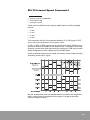
two or more signals were allocated to a single pin.
ATTENTION
Restart servo drive after signal assignment.
59
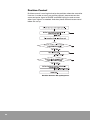
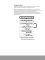
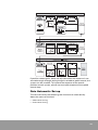
Position Control
Position control is moving the load to the position where the controller
instructs. In order to carry out position control, please connect the
command pulse signal to PULSE and SIGN input pins and connect
other input signals as needed. And then please follow the command
below for set-up.
Position Control Set-up Sequence
60
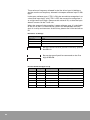
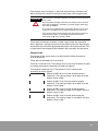
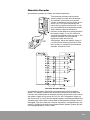
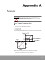
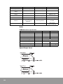
Three types of command are inputed through the four pins of the
controller connector (CN1).
Position Control Wiring
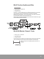
In the position control mode, the controller can input position
command in two ways. The first is line drive and the second is open
collector.
Line Drive Input
Open Collector Input
61
The maximum frequency allowed in the line drive input is 900 kpps,
and the maximum frequency allowed in the open collector input is 250
kpps.
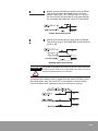
In the open collector type, if TR1 is ON, the servo drive recognizes it as
a low level input logic, and if TR1 is OFF, the servo drive recognizes it
as a high level input logic. Please set the value of R1, so that the input
electric current can be 7 to15 mA.
When the output of the controller is open collector type, it is desirable
to set Vcc to 24V. It is because the system can be operated securely
even in a noisy environment. At this time, please use 2.2 kΩ resistor at
R1.
Resistance to Voltage
Voltage (Vcc)
Resistance (R1)
24 V ± 5 %
2.2 kΩ
12 V ± 5 %
1 kΩ
5V±5%
180 Ω
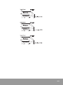
Set the control mode to position control by putting
0 at SEt-41.
Set up the type of position command on the first
digit of SEt-46.
Position Command Type Set-up
62
Set value
Logic
Multiplication
Pulse Type
0
Positive
-
CW+CCW
1
Negation
-
CW+CCW
8
Positive
-
Pulse Train + Sign
9
Negation
-
Pulse Train + Sign
2
Positive
1 multiplications
A Phase + B Phase
4
Positive
2 multiplications
A Phase + B Phase
6
Positive
4 multiplications
A Phase + B Phase
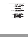
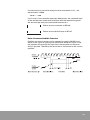
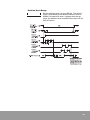
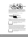
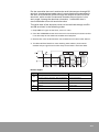
Please select the position control type by referring to the diagram.
Positive Logic Pulse
Negative Logic Pulse
63
Electric characteristics of the position command pulse are shown in
the diagram.
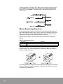
Electronic Gear
Electronic gear is a function to set the amount of load movement for
each input command pulse.
An encoder generating 2048 pulses per revolution can make a
complete revolution when the controller transmits 2048 pulses to the
drive. If the electronic gear is used, only 1000 pulses can make the
encoder finish a complete revolution.
In order to use an electronic gear, the speed reduction ratio from the
motor shaft to the system is needed.
ᵄ㋁⽸ d
64
⯜䉤㢌G䟀㤸㍌
㺐㦹GὤẠ⺴㢌G䟀㤸㍌
The speed reduction ratio is the ratio of revolutions of the system to
the motor. If the system make one revolution when the motor makes
five revolutions, the speed reduction ratio is 5. If the system make five
revolutions when the motor revolves once, then the speed reduction
ratio is 0.2.
The numerator and denominator of the electronic gear can be
calculated as below.
(SEt-36) Numerator = Number of pulses of the encoder × Speed reduction
ratio
(SEt-37) Denominator = Number of pulses per a revolution of the motor
In the case of a ball screw whose speed reduction ratio is 1 and the
number of pulses of the encoder per one revolution is 5000, if the
controller approves 1000 pulses for the servo drive to make the motor
finish one revolution, the numerator of the electronic gear is 5000 and
the denominator is 1000.
The ball screw finishes one revolution with 1000 pulses and thus a ball
screw with 10 mm pitch can move 10 with one pulse command.
ATTENTION
As the denominator increases, the resolution becomes
higher. But the following expression should be satisfied.
Pulse of the encoder ✕ Speed reduction ratio ✕ 4 ≥
Denominator
In this case, the maximum denominator is 20000.
65
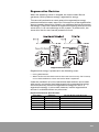
In the case of moving a belt 100 µm per one pulse, whose speed
reduction ratio is 5 and the number of pulses of the encoder is 2048,
the numerator of the electronic gear is 10240, and the denominator is
calculated by the following method.
Denominator = Movement distance of the load per revolution/Distance to
move by one pulse
If the diameter of the pulley on the load side is 50 mm and the distance
to move by one pulse of the controller is 100 µm, the denominator is
1570.
50 π mm/100 µm = 1570
In this case, if 1570 pulses are approved by the controller, the pulley at
the end devices makes one revolution and the straight moving
distance of the end load is 100 µm.
In case of rotating a turntable 0.1° per pulse, whose speed reduction
ratio is 3 and the number of pulses of the encoder is 2048, the
numerator of the electronic gear is 6144 and the denominator can be
calculated by the following method.
Denominator = Movement angle of the load per revolution/Angle to move
with one pulse
66
If the distance to move with one pulse of the controller is 0.1°, the
denominator is 3600.
360°/0.1° = 3600
In this case, if the controller approves 3600 pulses, the rotational load
of the end devices makes one revolution and the rotational angle of
the end load per one pulse command becomes 0.1°.
Please set the numerator at SEt-36.
Please set the denominator at SEt-37.
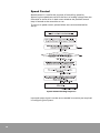
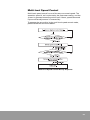
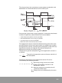
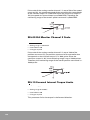
Pulse Command Inhibit Function
Position command counter can be stopped by setting /INHIB input,
which is the signal to ignore pulse command. While this input is ON,
the position command pulse input from the controller to the servo
drive is ignored. Therefore, the servo lock is maintained at the current
position.
67
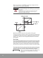
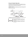
Position completion detection and in position detection
The user can set the timing for the position command completion at
the servo drive that received a position command from the controller,
and if the difference between the position of the load and the position
command is smaller than the set value, the signal for position
completion detection /P-COM can be displayed.
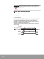
Set the decision range for displaying /P-COM signal
at SEt-18. The display range is 0 to 1000 pulse and
the default value is 10.
If the user sets the timing of the position command proximity at the
servo drive that received the position command from the controller
and the difference between the load position and the position
command is smaller than the preset value, the in position detection
signal /NEAR can be displayed.
Set the decision range for displaying /NEAR signal
at SEt-22. The display range is 0 to 1000 pulse and
the default value is 20.
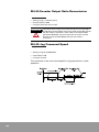
The motions required at the moment of position completion can be
shortened if /NEAR signal and /P-COM signal are used together, so that
the controller can confirm the in position signal before position
completion detection signal and prepare for the next sequence. Setting
these parameter does not affect the accuracy of the final position
decision.
ATTENTION
68
If the position completion range is large while the system is
operating at a low speed, /P-COM output signal can be kept
ON.
Position Error Range
Set the position error range at SEt-33. The setting
range is 0 to 65535 pulse and the default value is
25000. If the position error is bigger than the set
value, the position error overflow servo alarm (E.33
PoF) will occur.
69
Speed Control
Speed control is used for the purpose of controlling speed by
approving the speed command in the form of analog voltage from the
controller to servo drive in both cases whether the position control
loop is formed at the controller or not.
To carry out speed control, please follow the command below for
set-up.
Speed Control Setting Sequence
Input and output signals can be set as needed in case they are required
in configuring the system.
70
Speed Control Wiring
Speed Command
Set the speed command gain at SEt-01. The setting range is 10 to 6000
RPM/1V or RPM/10V. The default value is 500.
The unit setting of SEt-01 is set up on the second
digit of SEt-46.
When the second digit of SEt-46 is 0
Speed Command (RPM) = Speed Gain (RPM/V) × Input Voltage (V) When
the second digit of SEt-46 is 1
Speed Command (RPM) = Speed Gain (RPM/10V) × Input Voltage (V)
71
When the speed gain is 500 RPM/V and the input voltage is 6V, the
motor revolves at the speed of 3000 RPM.
ATTENTION
The tolerated range of the input voltage is DC V. An error can
occur if the input voltage is out of this range, and it cannot be
recognized.
If torque command is higher than the preset maximum
torque of the motor, a warning for excessive torque
command (A.10 OSC) will occur.
Speed command gain determines the gradient of the graph.
The motor sometimes revolves in boths cases where the controller did
not approve the speed command or it approved the speed command
with 0V. This is because of the voltage offset between the controller
and the drive.
Zero Clamp
Even if the analog speed command of the controller is 0V at the speed
command offset automatic adjustment, a little bit of offset voltage can
exist at the servo drive input terminal, which may cause the motor to
slowly rotate. In this case, using the zero clamp function can prevent
the motor from revolving a small amount caused by the offset voltage.
To use zero clamp function, please set the control mode at 5. Once zero
clamp input port is set, the zero clamp input terminal should be ON to
activate it. If the port is not set, it will be automatically activated.
Please set the speed zero clamp level at SEt-17. The
setting range is 0 to 5000 RPM and the default
value is 0.
72
If the CN1 connector pins where the zero clamp function is allocated
are ON, the voltage command below the level set at SEt-17 will be
ignored. When the value of the speed command surpasses this level
again, the motor will accelerate to the value of the command.
In Speed Function
/V-COM signal displays that the error between the motor revolution
speed and the speed command value is kept within a certain range.
This signal can be used as an interlock signal at the controller just as
the position completion detection /P-COM signal at the position control
mode can.
Please set the decision range for in speed match at
SEt-18. The setting range is 0 to 1000 RPM and the
default value is 10.
If the in speed is 100 and the speed command is 2000 RPM, /V-COM
signal is ON and displayed when the actual revolution speed is 1900
RPM or higher and 2100 RPM or lower.
73
Revolution Detection
/TG-ON signal shows that the servo motor is revolving faster than a
certain speed. This signal can be used as a condition to assess the
status of the motor while changing the control mode from the
combination control mode.
Please set the revolution detection level at SEt-16.
The setting range is 1 to 5000 RPM and the default
value is 20.
If the revolution detection level is set too low, a minute revolution can
cause the /TG-ON signal to be displayed.
Speed Limit
To avoid excessive motions in the load, the servo motor can be used
within a limited regular speed.
The speed limit is set by the user at SEt-67. Therefore, the servo drive
operates under the preset limit even if the controller approves a speed
command faster than the set value of the speed limit.
Please set the speed limit method at the third digit
of SET-45.
The set values are as follows.
0: Motor Maximum Speed (default value)
1: SEt-67 Value (RPM)
2: Analog Speed command (Operates in all modes except the speed
control mode)
3: The smaller value between the motor maximum speed and SEt-67
If setting value is bigger than the maximum speed of the motor, speed
is limited to that maximum speed.
Please set the speed limit level at SEt-67.
The setting range is 1 to 5000 RPM and the default
value is 5000.
When the speed limit is set at 1000 RPM, even if the controller
approves a speed command for 1500 RPM, the servo motor operates
at the speed of 1000 RPM. In this case, the signal for speed limit
detection /V-LMT can be allocated, so that the /V-LMT signal can be
displayed when the motor speed is bound by the speed limit.
74
Torque Control
Torque control mode is used when the tension or pressure of the
system should be controlled by using the servo drive.
Set the voltage appropriate for the required torque input from the
controller. Various set-values for the motor’s operating torque limit are
commonly applicable to position or speed control mode.
To operate the servo drive in torque control mode, please connect
analog torque command to corresponding input pins and follow the
setting command.
Torque Control Setting Sequence
75
Torque Control Wiring
Torque Command
Please set torque command gain at SEt-05. The
setting range is 0 to 100%/3V and the default value
is 100.
Torque = (Torque Command Gain × Input Voltage × Rated Torque)/100
When torque command gain is 100%/3V and input voltage is 3V, 100%
torque (rated torque) is generated.
76
If the torque command gain is 100%/3V and the input voltage is 9V,
300% torque, the maximum torque of the motor, will be generated.
ATTENTION
The maximum allowed voltage of the torque command input
is DC ±10V.
If the standard voltage fluctuates, the torque command can
also change together. Therefore, a power supply with high
accuracy is needed.
If minute torque adjustment is required, please use a multirevolution variable resistor which revolves over 10 times.
If the torque command is bigger than the preset maximum
torque of the motor, an warning for excessive torque
command (A.08 OtC) will be issued.
The motor sometimes revolves in both cases where the controller
didn’t approve a torque command at the offset automatic adjustment
and where the controller approved the torque command with 0V. This
is because of the voltage offset between the controller and the drive.
Torque Limit
The torque of the servo motor can be limited in either forward or
reverse direction.
There are two methods to limit torque.
The first is internal limit. The internal limit is the limit of the drive itself
by setting parameters regardless of external signals.
The second is external limit. The external limit is determined
according to input signals.
Please set SEt-10 to limit the forward torque
internally. The setting range is 0 to 300% and the
default value is 300.
Please set SEt-11 to limit the reverse torque
internally. The setting range is 0 to 300% and the
default value is 300.
Please set SEt-12 to limit the forward torque
externally. The setting range is 0 to 300% and the
default value is 100.
Please set SEt-13 to limit the reverse torque
externally. The setting range is 0 to 300% and the
default value is 100.
77
/P-TL signal is used to externally limit the forward torque, and /N-TL
signal is used to externally limit the reverse torque. These external
torque limits have priority over internal torque limits. Internal limits
are used to retrain the maximum value of the motor’s operating torque
(or output torque) within a fixed range so that the load system or
operation targets can be protected.
Usual range of the motor’s available torque is as follows.
Depending on the type of a motor, Instantaneous maximum torque
can be 300% or less. If the torque limit is set higher than the maximum
allowed torque of the motor, the limit will be set at the Instantaneous
maximum torque of the motor and the preset limit will be ignored.
Please set SEt-14 and SEt-15 to limit the torque in
case of an overtravel. Setting range
0 to 300%, 300.
Internal torque limit is always effective. Therefore, if the external
torque limit and the torque limit to prohibit revolution are bigger than
the preset value for limiting internal torque, the external torque limit
and the torque limit to prohibit revolution become meaningless.
The status where torque is limited by the preset values can be
displayed to the controller by using /T-LMT signal. If the motor’s torque
is the same as the preset torque limit, /T-LMT signal will be displayed.
If the third digit of SEt-44 is 0, the motor will stop
by the torque set at SEt-14 and SEt-15, and if it is 1,
the servo will be OFF.
78
Multi-level Speed Control
Multi-level speed control is one of the ways to control speed. The
operation speed is set in advance by the parameter setting, and the
system is operated according to the input. Hence, speed command
input or offset adjustment is unnecessary.
To operate the servo drive in the multi-level speed control mode,
please follow the command below.
Multi-level Speed Control Set-up Sequence
79
Multi-level Speed Control Wiring
In the multi-level speed control mode, there is no external signal input
pin for each control mode including position control, speed control,
and torque control. The operation is carried out only by the external
input signal. There are four different input signals dedicated to multilevel speed control.
•
/C-DIR
•
/C-SP1
•
/C-SP2
•
/C-SP3
The revolution will be in the forward direction if /C-DIR signal is OFF
and in the reverse direction if the signal is ON.
/C-SP1, /C-SP2, /C-SP3 signals can be combined in eight different ways
for which revolution speed can be determined. The motor’s revolving
direction can be controlled separately by engaging /C-DIR input to each
speed designated to each speed command.
80
Multi-level Speed
Speed
Parameter
Stop command
Default value
(RPM)
/C-SP3
/C-SP2
/C-SP1
0
0
0
0
Internal Speed
command 1
SEt-26
100
0
0
1
Internal Speed
command 2
SEt-27
200
0
1
0
Internal Speed
command 3
SEt-28
300
0
1
1
Internal Speed
command 4
SEt-79
400
1
0
0
Internal Speed
command 5
SEt-80
500
1
0
1
Internal Speed
command 6
SEt-81
600
1
1
0
Internal Speed
command 7
SEt-82
700
1
1
1
In the multilevel speed control mode, the motion of the motor changes
according to the input signal.
Set the acceleration time and deceleration time within the range that
won’t undermine the response of the system in order to ease the
impact of speed change.
81
Acceleration time is the time required for the motor to reach the rated
speed from standstill.
Please set the acceleration time at SEt-19. The
setting range is 0 to 60000 ms and the default
value is 200.
The diagram shows that the time for execution compared to command
was extended as much as the deceleration time.
Deceleration time is the time required for the motor to slow down to a
halt from the rated speed.
Please set deceleration time at SEt-20. The setting
range is 0 to 60000 ms and the default value is 200.
82
Combination Control
Position control, speed control, torque control, and multi-level speed
control are the basic controls. Basic controls can be used in
combination depending on the user’s circumstances.
/C-SEL signal is used to shift control mode between the two modes
that are combined. If the combination control mode is used, /C-SEL
signal must be used.
Combination Control Mode List
Set-up (SEt-41)
Control Mode
/C-SEL OFF
/C-SEL ON
6
Torque + Speed Mode
Torque Mode
Speed Mode
7
Position + Torque Mode
Position Mode
Torque Mode
8
Position + Speed Mode
Position Mode
Speed Mode
13
Position + Multi-level
Speed Mode
Position Mode
Multi-level Speed
Mode
14
Speed + Multi-level Speed
Mode
Speed Mode
Multi-level Speed
Mode
15
Torque + Multi-level
Speed Mode
Torque Mode
Multi-level Speed
Mode
Please set the combination control mode at SEt-41
If the combination control mode is set at SEt-41 and
/C-SEL signal is not allocated, a warning will be
displayed as shown in the diagram.
When the system is in operation under one of the two control modes
that are combined in the combination control mode, input for the other
control mode will be ignored. For instance, when the system is in
operation under the speed control mode, position command pulse or
analog torque command will be ignored. The input for those
command will be valid only when the control mode is changed by
/C-SEL signal to the relevant control mode.
Caution is needed when changing the control mode under the
combination control mode. In the case of changing the control mode
just depending on /C-SEL signal, it can cause damage to load or
unstability to servo drive in certain circumstance.
83
Combination control mode including position control is changed when
the following conditions are met.
Control Mode Changing Condition
Control Mode
(SEt-41)
7
/C-SEL OFF
Torque Control → Position Control
Position Control → Torque Control
Revolution Speed < SEt-16 set value or torque
command < (10%* rated torque)
position command pulse input = 0
(position command_actual position) <
SEt-18set value, continued for 16 ms
Speed Control → Position Control
Position Control → Speed Control
Revolution Speed < SEt-16 set value
Position command pulse input = 0
(position command_actual position) <
SEt-18set value, continued for 16 ms
Multi-level Speed Control → Position Control
Position Control → Multi-level Speed Control
Revolution Speed < SEt16 set value
Position command pulse input = 0
(position command_actual position) <
SEt-18set value, continued for 16 ms
8
13
84
/C-SEL ON
5
Tuning By Gain Adjustment
Overview
Users need to adjust the servo drive depending on the status of the
load in order to control different loads for the best performance. This is
the gain adjustment. And tuning is making the motor connected to the
drive perform its best through the gain adjustment.
Gains can be categorized as below.
•
System Gain
•
Basic Gain
•
Applied Gain
System gain is changed according to the inertia of the system and is
the same with the bandwidth of the servo drive’s overall speed control
loop. This gain can control the five basic gains at the same time.
•
System Gain (SEt-42)
Basic gain is categorized in five items that are essential for tuning.
•
Speed Loop Proportional Gain (Nms, SEt-02)
•
Speed Loop Integral Gain (Nms2, SEt-03)
•
Position Loop Proportional Gain (rad/s, SEt-04)
•
Torque Command Filter (rad/s, SEt-06)
•
Speed Command Filter (rad/s, SEt-40)
Applied gains are categorized into four items with distinct functions.
•
Position Command Filter (rad/s, SEt-35)
•
Vibration Suppression Filter (Hz, SEt-47)
•
Position Feedforward Gain (%, SEt-34)
•
Position Feedforward Filter (rad/s, SEt-07)
And there are four parameter needed for tuning.
•
P Control Shift Switch (SEt-54)
•
P Control Shift Reference Value (SEt-55, SEt-56, SEt-57)
•
Speed Bias Amount (RPM, SEt-38)
•
Speed Bias Application Range (pulse, SEt-39)
85
In tuning, the inertia ratio should be
considered first for the optimum
performance of the servo drive system.
The inertia ratio is the ratio of the inertia
of the load to the that of the motor’s
rotor. If the rotor’s inertia is 3 gf.cm.s2
and the load’s inertia is 30 gf.cm.s2, the
inertia ratio is 10.
Inertia Ratio = Inertia of the Load/Inertia of the Motor’s Rotor
Please set inertia ratio at SEt-66. Setting range
is 0 to 600 (0.1 times) and the default value is 30.
The default value 30 indicates that the inertia ratio
is 3.
ATTENTION
Once the inertia ratio is set, the servo drive adjusts basic
gains according to the inertia ratio. Therefore, adjustment of
the inertia ratio should be done carefully.
Set the system bandwidth.
If auto tuning or user changes the inertia ratio
(SEt-66), it automatically set the system gain
(SEt-42) and the basic gain based on this value.
The servo drive uses position command of the controller device to
generate speed command, and the speed command generate torque
command and transmit them to the servo motor. Thus all of the basic
gains should be set properly in case of using position control mode.
Even if the gains related to position control are appropriate, the best
tuning cannot be carried out if the gains related to torque or speed are
not properly set.
86
If position-related gains alone are adjusted when the response is not
secured enough through setting the gains related to speed control, the
system can be unstable. To improve the response of the overall
position control system, please secure ample response of the speed
control loop.
Gain Automatic Set-up
The servo drive has the following two functions to automatically
detect the status of the load.
•
Offline Auto Tuning
•
Online Auto Tuning
87
Offline Auto Tuning
Offline Auto Tuning automatically detects inertia ratio, friction
coefficient, and resonance frequency, and sets basic gains accordingly.
Please set SEt-69 as below according to the type of the system.
System Type
SEt-69
Low Rigidity (Belt)
20
Medium Stiffness
30
High Rigidity (Ball Screw)
45
The execution procedure of offline auto tuning is as below.
1. Offline autotuning (USr-02) is executed automatically.
2. Inertia ratio and system gain are automatically set.
3. 5 different basic gains are automatically set.
4. The response of drive will be improved.
The value set on the third digit of SEt-58 represents
100 RPM. For instance, if the set value is 8, it
means 800 RPM.
Revolution speed can be set at offline auto tuning.
Inertia ratio (SEt-66) can be directly set by the user.
Online Auto Tuning
Online auto tuning is used when the load constantly changes during
operation. It constantly changes the gain value according to the status
of the load in order to maintain response of the system even if the
status of the load changes.
In the following cases, offline auto tuning is better than online auto
tuning.
88
•
When the inertia ratio of the load changes minutely or rapidly during
operation.
•
When the inertia ratio of the load alternates between two values
•
When a large torque is not generated during the operation because the
acceleration or deceleration time is too long, or the maximum revolving
speed limit or torque limit is set low.
Setting Tuning Coefficient on online
To use online auto tuning, set the coefficient at the
fourth digit of SEt-58. Setting range is 0 to 9. If the
fourth position is not 0, online auto tuning function
will be used.
As the value is set higher, the system becomes
more sensitive to load fluctuation.
ATTENTION
If the load fluctuates radiply, online auto tuning coefficient
needs to be set high, but caution is needed because the
system can be momentarily unstable in an environment
where the load fluctuates excessively.
While online auto tuning is being used, please raise system gain (SEt42) if the response of the control loop drops and lower it if the system
makes noise or vibrates.
Gain Manual Set-up
To set up gains manually, please follow the command below.
1. Set the inertia ratio and system gain automatically executing offline auto
tuning.
2. If the response of control loop is lowered, raise the system gain value. If
the load system makes noise or vibrates, lower the set value until vibration
or noise stops.
If the load system is not composed of optimum combination by 1 and 2
above, adjust the gain minutely as 3, 4 and 5 hereunder.
3. Fine tune the value of each basic gain.
(Speed loop proportional gain, Speed loop integral gain, Position loop
proportional gain, Torque command Filter, Speed command Filter)
4. Fine tune the value of each applied gain.
(Position command filter, Vibration suppression filter, Position feedforward
gain, Position feedforward filter)
5. Set the four parameter required for tuning.
(P control shift switch, P control shift reference value, Speed bias
application range, Speed bias amount)
If the response drops after offline auto tuning, raise the system
bandwidth (SEt-69) a little and run offline auto tuning again. Secure the
maximum response by raising the system gain (Set-42) to the level
before vibration or noise starts.
When the maximum response is secure while the
inertia ratio (SEt-66) is set accurately and the load
system has no vibration or noise, the system gain
can be set as high as possible and becomes the
bandwidth of the overall speed control loop.
89
If the system gain (SEt-42) is raised, the overall
gains increase and the response improves. If this
value is changed, the five basic gains change, and
the inertia ratio is referred to in this process. If the
value is set too high for the load condition,
vibration or noise can be generated.
By setting SEt-42, basic gains are changed by referring to the inertia
ratio (SEt-66). As the value is set higher, the response improves. But if
the value is too high for the load condition, vibration or noise can be
generated.
ATTENTION
The value set last takes priority in the gain set-up. For
instance, even after the speed loop proportional gain is
changed by setting the system gain (SEt-42), if the speed loop
proportional gain (SEt-02) is set again, this value is valid.
The function of the system bandwidth (SEt-69) is
the same as the function of the system gain (SEt42), but while the system gain changes according
to the inertia ratio, the system bandwidth remains
parameter even if the inertia ratio changes.
When the inertia ratio is changed by auto tuning or user, change the
system and basic gain refering to SEt-69 and inertia ratio.
Torque Control Gain
Torque control gains include vibration suppression filter and torque
command filter gain. The diagram below shows the application
process of torque control-related gains.
Vibration suppression filter restrains the vibration caused by the load’s
resonance when the load system resonates in a certain frequency
band. If properly set, it allows other gains to be raised, so that the
stability and response of the overall system are improved greatly. But
if it is set incorrectly, it can cause vibration or noise.
Set vibration suppression filter at SEt-47. The
setting range is 0 to 10000 Hz, and the default
value is 10000.
Torque command filter limits the high frequency element in the torque
command. By limiting the high frequency element higher than the
preset level, torque command itself can be softened to reduce
vibration and noise.
90
Please set torque command filter at SEt-06. The
setting range is 0 to 60000 rad/s, and the default
value is 1800.
As the value is higher, the response can improve. But if it is set too
high, it can cause vibration. If the load is a belt or chain system, fast
response is not expected because of the lowered stiffness.
If speed control or position control related gain is raised excessively
when the value is set at lower torque command, it can oscillate. In the
case of these loads, it is hard to set the torque command filter higher
than 1000 rad/s. Please refer to the table below for set-up.
Load Type
SEt-06
Directly-coupled Disk
4000
Ball Screw Coupled directly
2000 to 3000
Belt
500 to 1000
Speed Control Gain
Speed control gains include speed loop proportional gain, speed loop
integral gain, and speed command filter. The picture below shows the
application process of the speed control-related gains.
Raising the speed loop proportional gain can improve the response of
the speed control loop. Please set the value as high as possible within
a range that won’t cause vibration.
Speed loop integral gain can remove error at the steady state by
responding to even very small input. Raising the speed loop integral
gain can improve the response and reduce completion time. Please set
it low in an environment where the inertia of the load is big or
vibration can easily occur.
The speed command filter can limit the high frequency element in the
speed command to soften the speed command itself. If its value is 0,
speed command filter will not be used.
91
To set up the gains related to speed control, please follow the
commands below.
1. Set the speed loop proportional gain at SEt-02. The setting range is 0 to
1500 Nms, and the default value is 80. Please raise the value as high as
possible as long as it doesn’t cause vibration or noise.
2. Set speed loop integral gain at SEt-03. The setting range is 0 to 20000
Nms2and the default value is 200. Raise the value gradually while watching
the responses in the excessive period such as overshoot, completion time,
vibration or noise. If it is set too low, the response can drop. But if it is too
high, vibration or noise can be generated.
3. Please set speed command filter at SEt-40. The setting range is 0 to 4000
rad/s and the default value is 1000. Please lower the value in an
environment where the position control-related gain of the higher control
device is set too high or there is too much noise.
4. It is desirable to set the value of torque command filter (SEt-06) as high as
possible as long as no vibration is generated from the load.
The values of the speed loop proportional gain and the speed loop
integral gain are supposed to be scaled according to the inertia ratio.
Therefore, if the load inertia ratios of a 100 W motor and a 1 KW motor
are the same to be about 10 times, appropriate values of the speed
loop integral gains are the same as well.
Position Control Gain
Position control gain includes feedforward gain, position feedforward
filter, and position loop proportional gain.
The diagram below shows the application process of position controlrelated gains.
Position command filter can restrain the high frequency element in the
position command to soften the position command itself. If its value is
0, position command filter will not be used.
Raising the value of position loop proportional gain improves the
response of the position control.
92
To set up position control-related gains, please follow the commands
below.
1. Set the default position loop proportional gain at SEt-04. The setting range
is 0 to 500 rad/s and the default value is 60.
2. Slowly raise the value of speed loop proportional gain (SEt-02).
3. Lower the value of speed loop proportional gain to 80 to 90% if vibration or
noise is generated from the load.
4. Raise the value of position loop proportion gain as high as possible in the
transient period as long as no vibration or noise is generated.
5. Raise the value of speed loop integral gain (SEt-03) gradually while
watching the responses in the transient period such as overshoot,
completion time, vibration or noise. If it is set too low, the response can
drop. But if it is too high, vibration or noise can be generated.
6. When necessary, the value of position command filter (SEt-35) can be
lowered to restrain transient change of the position command.
7. It is desirable to set the value of torque command filter (SEt-06) as high as
possible as long as no vibration is generated from the load.
Methods to Get Quick Responses
Position Feedforward Function
Position feedforward applies the differentiated element of the position
command to speed command in the position control mode by way of
feedforward. Consequently, transient response characteristics are
improved and the position decision time is reduced.
Set the position feedforward gain at SEt-34. The
setting range is 0 to 100% and the default value is
0. Setting the value high will improve the response
of the position control.
Position feedforward filter restrains the high frequency element in the
position command to soften the position command itself.
Set the feedforward filter at SEt-07. The setting
range is 0 to 5000 rad/s and the default value is 0. If
its value is 0, position feedforward filter will not be
used. When the value of the torque command filter (SEt-06) is set high,
if overshoot or excessive vibration occurs, please lower the value of
the position feedforward filter.
93
When the position feedforward function is used, the speed command
varies highly in response to the change of position command.
Therefore, if the position command input fluctuates rapidly, in cases of
rapid acceleration or deceleration, feedforward can cause overshoot.
To reduce position command completion time in this case, raise the
value of the torque command filter (SEt-06) slowly and locate the
appropriate value. Or it may be desirable to restrain the high
frequency element of the position feedforward by using the speed
command filter (SEt-40) or soften the position command itself by using
the position command filter (SEt-35).
ATTENTION
Using online auto tuning and position feedforward function
together can make the system unstable.
Speed Bias Function
In the position control mode, another way to reduce position
completion time is to apply bias to speed command according to
position error. When this function is used, position error can be
reduced quickly as faster speed command is issued to reduce error at
the area with large position error. This has the same effect as a
relatively higher position proportional gain is applied to an area with
large position error, and by doing so, the position completion time
near the steady state can be reduced.
Please set the speed bias amount at SEt-38. The
setting range is 0 to 450 RPM and the default value
is 0. If the position error is bigger than the preset
value of the speed bias application range (SEt-39), a faster speed
command that includes the value of the speed command set here will
be issued.
Please set the speed bias application range at
SEt-39. The setting range is 0 to 250 pulse and the
default value is 10. When the position error is
bigger than the value set here, the speed bias amount (SEt-38) will be
added to the speed command.
If the absolute value of position error is bigger than the preset value of
the speed bias application range, the speed command equal to the
preset value of the speed bias amount will be added to the position
control output. Please adjust the speed bias amount and the speed
bias application range alternately while watching transient response. If
the speed bias amount is set too high or the speed bias application
range is set too low, vibration can occur.
94
P/PI Mode Set-up Function
By setting the speed loop integral gain (SEt-03) in the speed control or
position control mode, the system will be able to respond to subtle
changes of the command and can be controlled accurately and the
error at the steady state can be 0. If the speed loop integral gain is set
too high in order to increase the response, overshoot may occur with
the speed response in the transient status, which would increase
position completion time. Therefore, position completion time can be
reduced by setting the integral gain to 0 for an instant to restrain
overshoot when necessary. In this case, the speed control loop is used
in the form of a P controller after changing it from a PI controller.
There are two ways to use the speed control loop by changing it from
PI controller type to P controller type.
•
Input P Control Shift Control by /P-CON Signal.
•
P/PI Mode Shift by Parameter Set-up.
The type of the speed controller is determined in the following way
according to the input channel signal after /P-CON. Signal is allocated
to the input channel.
Therefore, at the controller, a program to shift the speed controller
from PI controller type to P controller type can be made by assessing
the analogue output such as the speed of the servo drive and torque
and the output like /P-COM, /V-COM, /TG-ON.
95
Description on Second Digit of SEt-54
ATTENTION
If overshoot is small, do not use the control by the /P-CON
signal.
When a small amount of offset is included in the speed
command on the speed control mode, using the P controller
type can cause the motor to not react to the offset set at 0
speed command and remain still.
P/PI mode shift function by the parameter set-up can be used in the
following cases.
•
When the internal torque command is bigger than a certain value (%)
•
When the speed command is bigger than a certain value (RPM)
•
When the position error is bigger than a certain value (pulse)
Set the P control shift switch at the first digit of
SEt-54. The set-up can be done as shown in the
table below.
96
Set Value
Function
0
Do not use P/PI mode shift.
1
Shifts when the torque command is bigger than P control shift reference
value (%).
2
Shifts when the speed command is bigger than P control shift reference
value (RPM).
3
Shifts when the position error is bigger than P control shift reference
(pulse).
Please set the P control shift reference for a torque
command at SEt-55. The setting range is 0 to 300%
and the default value is 100.
Please set the P control shift reference for a speed
command at SEt-56. The setting range is 0 to 3000
RPM and the default value is 100.
Please set the P control shift reference for a
position error at SEt-57. The setting range is 0 to
10000 pulse and the default value is 100.
The picture below shows the speed response when the speed
regulator is changed from PI to P by torque command in the transient
response status.
In the transient status of acceleration area or deceleration area, if the
torque command is bigger than the P/PI mode shift reference, the
speed regulator will be P type and PI controller type in other areas.
ATTENTION
/P-CON signal will be shifted prior to P control shift switch and
the reference set-up. In other words, regardless of the current
motor status and the set-up of these values, the speed
regulator will be P controller type if /P-CON signal is ON.
To reduce the position completion time or overshoot of the
speed response by using this function, P control shift switch
and the reference should be set up properly. Please closely
watch transient responses of speed, torque, and position for
optimum set-up.
97
Default Torque Bias
Default torque bias prevents a fall due to gravity of the vertical load
during the initial operation.
When the load is vertical and the servo
ON signal is applied to activate the
motor, the load can fall because of
gravity. And when the servo ON, servo
OFF signals are applied, the motor brake
should be applied or released. If the
timing is not properly adjusted, the load
can fall momentarily, causing vibration
in the machine. This characteristics of
the vertical load causes overshoot and
postpones position completion.
Moreover, the servo alarm can go off as
the system tries to activate the motor
while the brake is applied.
Default torque bias is used to prevent the load from falling by gravity
during the process of controlling the vertical load. The default torque
equal to the falling load is applied to the motor in a reverse direction of
the falling motion when the servo ON signal is applied. If default
torque bias is properly set according to the falling force of the load, the
falling of the vertical load can be prevented in the early stage of the
operation.
By adjusting torque command offset (SEt-64 and
SEt-65), revolution of the motor can be prevented.
ATTENTION
98
In case of controlling a vertical load, please use brake motor
or install braking device to use the motor.
The set-up sequence of the default torque bias is as follows.
1. Check the revolving direction of the motor and the movement direction of
the load.
2. Stop the load at a certain position by using 0 speed control or normal
position control.
3. Check the torque command value while maintaining the system at a halt
and set the value at SEt-64 if it is in the forward direction and at SEt-65 if it
is in the reverse direction.
4. Fine tune the values with the current set values as standard while watching
the torque of the motor, speed, and position response.
If the default torque bias is fixed at a certain value but not 0, the
control begins at the moment of the servo ON and the value of the
torque command begins from the set value of the parameter. Since the
torque to maintain the motor at the current status is generated from
the beginning, the temporary fall of the load can be prevented.
Therefore, overshoot of the speed response can be restrained, and
consequently the position completion time can be reduced.
ATTENTION
If the default torque bias is set too high, the load can
temporarily rise at the moment of the servo ON.
Gain Alternation
In some cases, the load alternates between the two different statuses.
For instance, a robot repeats a motion to lift up an object, carry it
somewhere, leave it there and come back to the original position at no
load status. If this kind of motion is repeated very quickly, online auto
tuning cannot be done smoothly. And if the same gains are used to
operate different load conditions, the response drops in a one-load
situation. In this case, /G-SEL signal is helpful.
99
If all the different load conditions are categorized into two, the primary
gains and the secondary gains, the response of different load
conditions can be satisfied.
/To use /G-SEL signal, please set the optimum gain under the no-load
condition. And then set the optimum gain in a situation with a load.
And then let the /G-SEL signal be input in both conditions where a load
exists or not.
ATTENTION
100
When the gain alternation function is used, online auto tuning
cannot be carried out.
6
Application
Motor Stop
The servo drive aborts the operation and stops the motor under the
following circumstances except for the case where the motor is
stopped by normal operation.
•
Servo Alarm Occurs
•
Overtravel Occurs
The methods to stop the motor can be set up depending on the
reasons for the stoppage.
•
Stop by dynamic brake
•
Control stop as in normal operation
Overtravel
If the load moves out of the movement range during operation, the
load system can be damaged. The breakage of the load system can be
prevented by installing limit sensors at the end of the movement
range.
Please make sure the load can move within the range that won’t touch
the sensors during operation. If the load moves out of the movement
range and the sensor generates a signal because of an unknown error,
the servo drive can stop the motor and protect the load system. The
signal emitted from the limit sensors while the motor revolves in the
forward direction is the P-OT signal, and is the N-OT signal while the
motor revolves in the reverse direction.
101
The overtravel signal is not the servo alarm but a signal to protect the
load system.
Please set the motor stop method in case of an
overtravel on the third digit of SEt-44.
Overtravel Stop method
Set Value
Function
0
Stop the motor while controlling torque normally.
1
Servo OFF.
Dynamic Brake
If a motor shaft is revolved manually after short-circuiting all the motor
cables (U, V, W) of the servo motor, the revolving load is bigger than
when the cables are not short-circuited. The drive uses this feature to
stop the motor. When the servo drive uses this feature to stop the
motor, it is called dynamic brake.
CSDP Plus servo drive has internal dynamic brake circuit.
If the motor cable is connected to the servo drive and the servo drive is
not enabled, the switch in the diagram below is short-circuited. This
means dynamic brake is working. And the servo drive can activate
dynamic brake by controlling the switch of dynamic brake according to
the parameter setting.
ATTENTION
102
Dynamic brake cannot be used with the motor stop method
which uses normal torque control.
When the motor needs to stop during operation, if the dynamic brake
stopped the motor, it is called dynamic brake stop. On the contrary, if
the friction of the load stopped the motor by itself, it is called Free Run
stop.
Please set the stop method of dynamic brake on
the first digit of SEt-44.
Dynamic Brake Stop Method
Set Value
Function
0
Stops by dynamic brake.
1
Stops by free run.
Please determine whether to maintain the dynamic
brake function after the motor has stopped on the
second digit of SEt-44.
Dynamic Brake Function After Stoppage
Set Value
Function
0
Maintains the dynamic brake function after the dynamic brake stoppage
1
Releases the dynamic brake function after the dynamic brake stoppage
Motor Brake
If a mechanical brake is mounted on the motor, it can be used in the
following cases.
•
When the load can move by gravity
•
When the load should be kept from falling in case of power OFF or servo
off.
The drive cannot use voltage and current high enough to control the
motor brake directly. Therefore, the motor brake cannot be directly
connected to the drive. It can be controlled indirectly by building an
external circuit through a relay.
103
The external circuit to control the motor brake is built as shown below.
Please set the waiting time for brake release at
SEt-32. The setting range is 0 to 10000 10 ms and
the default value is 0.
If the motor brake is working at the moment when the drive activates
the motor, it should be released first. In this case, if the brake is
released before the servo is ON, the vertical load will drop for a
moment. Therefore, the servo should be ON first so that the drive can
control the vertical load so that it won’t fall, and then the brake should
be released. This configuration is to secure the time for the servo drive
to release the motor brake from the moment the servo is ON.
Brake Inactive delay Time
Please set the servo OFF delay time at SEt-29. The
setting range is 0 to 1000 [10 ms] and the default
value is 0. This configuration is used to secure the
time before the drive activates the motor brake
after the controller delivered the servo OFF
command.
Servo Off Delay Time
104
Please set the brake output waiting time at SEt-31.
The setting range is 0 to 1000 [10 ms] and the
default value is 50. This configuration is used for
the time for the motor brake to start working after
the controller delivered the servo OFF command.
Brake Active Relay Time
Please set the brake output start speed at SEt-30.
The setting range is 0 to 1000 RPM and the default
value is 100.
Braking Application Speed
ATTENTION
The brake mounted on the motor cannot be used to stop the
revolving motor. Please use it right before the stop or use it to
keep the stopped motor at a standstill.
If the brake active delay time is longer than the servo OFF delay time,
the brake works after the servo OFF is completed as shown below.
Then the vertial load is bound to fall for a moment by gravity.
105
On the contrary, if the servo OFF delay time is longer than the brake
active delay time, the brake on the motor starts working before the
servo OFF is completed as shown below, preventing the fall of the
vertical load.
Motor Revolving Direction
As for the controller and its wiring, even if the revolving direction of
the motor determined by pulse input is wired in a different way from
the user’s intention, the revolving direction can be reversed by the
parameter set-up with no need to modify the wiring.
Please set the motor’s revolving direction at the fourth position of
SEt-45.
Motor’s Revolving Direction
Set Value
Function
0
Revolves in the forward direction.
1
Revolves in the reverse direction.
Forward direction is counterclockwise when the motor is looked at
from the front. The reverse direction is clockwise when the motor is
looked at from the front.
In the jog operation mode, the motor’s revolving direction and the key
button switch are fixed to each other. Therefore, this function cannot
be used for jog operation.
106
Regenerative Resistor
When the operating motor is stopped, the motor works like the
generator, which produces energy, regenerative energy.
The servo drive absorbs to some extent the regenerative energy
produced while the motor stops. But if the amount of the regenerative
energy exceeds the existing capacity, an additional device to consume
the energy is required. If excessive regenerative energy overstrains the
servo drive, it can cause damage to the system. To prevent this, the
servo drive has its own internal protective circuit.
Regenerative Resistor
Regenerative energy is produced in the following cases.
•
During deceleration.
•
When the force of the load revolves the motor continuously. For instance,
minus load condition or when the vertical load is operated.
Under the condition of minus load where load revolves servo motor
with gravity and vertical load where continuing regenerative energy
occurs excessively, excessive regenerative energy can occur. If
regenerative energy is consumed, however, internal regenerative
resistor is available without any measures.
Regenerative Resistor Specifications
Servo drive
Capacitor
Internal Regenerative Resistor
CSDP-15BX2
2010 µF
50Ω, 125 W
CSDP-20BX2
2010 µF
25Ω, 125 W
CSDP-30BX2
2010 µF
25Ω, 250 W
CSDP-40BX2
2800 µF
25Ω, 250 W
CSDP-50BX2
3900 µF
25Ω, 250 W
107
Allowed Inertia Ratio (Based on the 50% usage rate of the regenerative resistor)
1.2kW
1.5kW
2kW
2.5kW
3kW
3.5kW
4kW
4.5kW
5kW
CSMD
8.0
5.0
6.0
5.0
3.0
3.0
2.0
1.5
CSMS
16.0
11.0
9.0
8.0
7.0
4.0
4.0
3.0
CSMF
6.0
CSMH
2.0
CSMK
1.3kW
13.0
RSMD
8.0
RSMF
6.0
RSMH
2.0
RSMK
13.0
RSMX
5.0
2.0
2.0
1.0
0.5
10.0
6.0
5.0
6.0
5.0
2.0
1.0
0.3
0.0
7.0
3.0
3.0
2.0
2.0
0.5
10.0
6.0
7.0
3.0
1.0
1.0
8.0
4.5
2.0
RSML
6.0
3.0
2.0
5.0
1.5
1.0
1.0
RSMN
6kW
0.3
0.0
2.0
5.0
1.5
Allowed inertia ratio application condition
Setting acceleration time
200 ms
1cycle
2 sec.
Operation Speed
Rated Speed
A regenerative resistor that users connect to the outside according to
the load is called the external regenerative resistor. The rated power of
the regenerative resistor consumes the regenerative energy produced
from the load system. If the produced energy is small enough, users
can set up the external regenerative resistor and increase the rated
power of the regenerative resistor, so that the regenerative energy
produced from the load system can be consumed.
There are two ways to increase the allowed power of the regenerative
resistor. The first is connecting the internal regenerative resistor and
the external resistor in parallel, and the second is mounting an extra
external regenerative resistor after removing the internal regenerative
resistor.
ATTENTION
ATTENTION
108
In case of increasing the rated power of regenerative resistor,
set the minimum resistor value according to capacity. (15Ω to
25Ω)
The temperature of a resistance for the regenerative resistor
can rise over 200° C under the rated load condition. Because
without an extra cooling fan, the temperature of the
regenerative resistor can go up excessively, please use 20%
or less of the rated power of the regenerative resistor.
This picture shows the case where a motor repeats acceleration and
deceleration on the horizontal basis with a fixed cycle.
Deceleration
Section
If the number of the motor’s actual repetition is more than the allowed
number of repetitions, please follow the command below.
•
Lower the preset speed as much as possible.
•
Set the deceleration time as long as possible.
•
Limit the torque as much as possible.
•
Make the inertia of the load system smaller.
The regenerative resistor should be selected among those that meet
the specifications of the user’s load system. As another way to select
the regenerative resistor, calculating the rated power of the necessary
regenerative resistor can help the user choose the optimum
regenerative resistor for the load system.
The formula to get the rated power WK of the regenerative resistor is
as follows.
EK
WK =
0.2 × T
T stands for the operation cycle and 2means the 20% of
the rated power.
The energy consumed by the regenerative resistor EK can be
calculated by the following formula.
EK = EM − (EL + ER + EC )
EM = Revolving energy of the servo motor
EL = Energy consumed by the load in the
deceleration section
ER = Heat loss energy consumed by the coil
resistance of the motor
EC = Energy that can be absorbed by the servo
drive
109
The revolving energy of the servo motor EM can be calculated by the
following formula.
J × (1 + n ) × N M2
EM = M
182
NM = Set Speed
JM = Motor Inertia
n = Inertia Ratio
The energy consumed by the load in the deceleration section EL can be
calculated by the following formula.
EL =
π
60
(N M × τ L × T D )
TL = Motor Torque
TD = Deceleration Time
If the energy consumed by the load is unknown, then calculate with
EL=0.
The heat loss energy consumed by the coil resistance of the motor ER
can be calculated as shown in the formula below.
Ɏ
3
ER = × R × L
KT
2
2
O P
ATTENTION
× TD
Ra = Phase Resistance
KT = Torque Parameter
Please make sure the rated power of the regenerative resistor
is calculated accurately. If the calculated rated power of the
regenerative resistor is bigger than the rated power of the
internal regenerative resistor, please remove the existing
resistor and set up an external regenerative resistor.
The units used in the aforementioned formula are as follows.
Units used in the formula for the regenerative resistor
Item
Unit
2 2
Energy
E = Joules = kgm /s
Torque
τ = Nm
Inertia
J = kgm2
Time
T = s = 1/60 Min
Speed
N = RPM = 60/2 π rad/s
Torque Constant
K T = Nm/A
The regenerative energy produced when continuous regeneration
sections occurred under the vertical load condition are called EG and
the selection standard of the regenerative resistor can be calculated as
shown below.
110
EK = EM − (EL + ER + EC ) + EG
EM = Revolving energy of the servo motor
EL = Energy consumed by the load in the
deceleration section
ER = Heat loss energy consumed by the coil
resistance of the motor
EC = Energy that can be absorbed by the servo
drive
Regenerative energy produced in the continuous regeneration
sections EG can be calculated as shown below.
EG =
2π
(N MG × τ G × TG )
60
NMG = Preset speed in the continuous
regeneration sections
τ G = Torque in the continuous regeneration sections
TG = Operation time in the continuous
regeneration sections
This diagram shows the case where the motor repeats acceleration
and deceleration on the vertical axis with a fixed cycle.
111
Set-up for Smooth Operation
By setting the acceleration/deceleration time and S operation time at
the servo drive, the system can operate more smoothly by easing the
possible impact from acceleration or deceleration.
Acceleration time is the time required for the motor to reach the rated
speed from standstill.
Deceleration Time is the time required for the motor to slow down to a
halt from the rated speed.
The diagram shows that the time for execution compared to command
got extended as much as the deceleration time.
Please set the acceleration time at SEt-19. The
setting range is 0 to 60000 ms and the default
value is 200.
Please set the deceleration time at SEt-20. The
setting range is 0 to 60000 ms and the default
value is 200.
112
As shown below, executing command in the form of an S curve at the
transitional points of acceleration or deceleration can make the
operation smoother.
Please set S operation time at SEt-21. The setting
range is 0 to 5000 ms and the default value is 0.
Assuming that the time required to execute the initial speed command
is 10 seconds, the total time required to execute the speed command
after setting acceleration/deceleration time will be 10 seconds +
deceleration time. And the total time required to execute speed
command after setting the S-curve operation time is 10 seconds +
deceleration time + S-curve operation time.
ATTENTION
S operation alone cannot be used without setting
acceleration/deceleration time. To use S operation, please set
acceleration/deceleration time that corresponds to the user’s
situation.
What is different from CSDP is that 0 should be set at SEt-21
not to use the S operation. Setting other values besides 0
enables S operation.
113
Speed Limit
Speed limiting methods are internal speed limit and external speed
limit.
•
Internal Speed Limit: Limit the speed through the setting of the servo drive
itself.
•
External Speed Limit: Limit the speed through the command from the
controller.
Internal Speed Limit
Internal speed limit works as the speed is limited by the value users set
at SEt-67. Therefore, the servo drive operates under the preset limit
even if the controller approves a speed command faster than the set
value of the speed limit.
Please set the speed limit at SEt-67. The setting
range is 1 to 5000 RPM and the default value is
5000.
External Speed Limit
If the user does not use the speed control mode and operates the
system in one of the other control modes, the analog speed command
input from external can be used to limit speed. If the speed control
mode is used, the external speed limit function cannot be used and the
speed can be limited by the internal speed limit.
Speed command gain (SEt-01) determines the relationship between
the analog speed command voltage and the speed command in the
speed control mode. When the speed control mode is not used, the
speed limit is the speed set by the relationship between the speed
command gain and the analog speed command voltage.
Please set the speed command gain at SEt-01. The
setting range is 10 to 6000 RPM/V and the default
value is 500.
The formula to get the external speed limit is as follows.
External speed limit (RPM) = Speed Command Gain (RPM/V) × Input
Voltage (V)
When the speed command gain is 500 RPM/V and the input voltage is
6V, the motor speed is limited at 3000 RPM and when the input voltage
is 10V, the speed limit is 5000 RPM.
114
Speed Limiting Method Selection
Please set the method to limit speed at the third
digit of SEt-45.
Speed Limiting Method
Set Value
Function
0
Does not use the speed limit function.
1
Limits the speed by the internal speed limit (SEt-67).
2
Limits the speed by the analog speed command input from the outside.
3
Limits the speed under the smaller value between the motor’s
maximum speed and the value of SEt-67.
Position Feedback to the Controller.
The servo drive controls the servo motor by using various information
from the encoder. And the servo drive can send the output of the
encoder information to the controller.
The servo drive outputs five different encoder signals in total to the
controller.
Encoder Signals Sent to the Controller.
Symbols
Function
Type
EA, /EA
Encoder A(/A) Phase Output
Line Drive
EB, /EB
Encoder B(/B) Phase Output
Line Drive
EC, /EC
Encoder C(/C) Phase Output
Line Drive
PS, /PS
Absolute encoder position Data output
Line Drive
/Z-PULSE+, /Z-PULSE-
Encoder Z (+/-) Phase Output
Open Collector
The direction of the encoder output pulse sent to the controller can be
changed.
Please set the direction of the encoder output pulse
at the first digit of SEt-46.
115
Direction of the Encoder Output Pulse
Set Value
Function
In the forward revolution, encoder output
phase A is displayed 90 degress in advance.
0
In the reverse revolution, encoder output
phase B is displayed 90 degrees in advance.
1
The servo drive can adjust the number of the encoder pulses through
the dividing circuit function before sending the input from the encoder
to the controller.
The formula to adjust the number of output pulse is as follows.
(Numerator/Denominator) ✕ Number of Encoder Pulse = Output to the
controller
If a certain type of encoder connected to the drive produces 2048
pulses per revolution and as many as 1000 pulses per revolution
should be sent to the controller, the numerator can be set to 1000 and
the denominator can be set to 2048.
(1000/2048) ✕ 2048 = 1000
Please set the number of output pulses per
revolution, which is the numerator, at SEt-23. The
setting range is 1 to 65535 pulse and the default
value is 2500.
Please set the number of encoder pulses per
revolution, the denominator, at SEt-24. The setting
range is 1 to 65535 pulse and the default value is
2500.
116
Even when the motor is revolving at a completely normal speed,
jittering of about 33 µs can be generated at the encoder output pulse
depending on the revolution speed.
ATTENTION
The servo drive cannot send more pulses than the number of
input pulses from the encoder to the controller. Therefore, the
numerator should always be the same as or smaller than the
denominator.
Analog Monitor
The servo drive can display the analog monitor signals with which the
user can check the actual control status through an oscilloscope.
Set the scale units of the analog monitor channel 1
and channel 2 at SEt-78.
Analog Monitor Output Type
Chosen Number
Types
Setting Range (1V)
0
Speed Command
1 to 500 RPM
1
Torque Command
1 to 30%
2
Position Command
1 to 5000 pulse
3
Speed Feedback
1 to 500 RPM
4
Torque Feedback
1 to 30%
5
Position Feedback
1 to 5000 pulse
6
Position Error
1 to 2500 pulse
7
Speed Error
RPM
8
DC-link Voltage
V
9
Θ (theta_cnt) Electrical
Angle
°
10
Pulse Command
Frequency
kHz
11
Inertia Ratio
%
12
Q Axis Current
A
13
D Axis Current
A
14
U Phase Current
A
15
V Phase Current
A
16
W Phase Current
A
117
Please set the scale of the analog monitor channel
1 at SEt-08. The setting range is 1 to 65535 /V and
the default value is 500.
Please set the scale of the analog monitor channel
2 at SEt-09. The setting range is 1 to 65535 /V and
the default value is 500.
If the scale of the analog monitor channel 1 is set to 500 of the speed
command (0), the speed command of the controller that corresponds
to the monitor output 1V is 500 RPM. Since the maximum output is 10
V, the speed can be monitored up to 5000 RPM. Therefore, the
monitoring range of the overall speed command is ±5000 RPM.
If the scale of the analog monitor channel 2 is 1000 of the position
command (2), the position command of the controller that
corresponds to the monitor output of 1V is 1000 pulses. As the
maximum output is 10 V, the position command can be checked up to
10000 pulses. Therefore, the monitoring range of the overall position
command is ±10000 pulses..
118
Absolute Encoder
An absolute encoder can detect the absolute position.
The absolute encoder uses external
battery power to store and remember
the position information of the load
system if the power supply of the servo
drive is cut. The error caused by the
noise during signal transmission is not
accumulated with the absolute encoder.
And it doesn’t require the default
position of the load to be adjusted when
the power supply is cut off, while the
incremental encoder does require it. The
absolute encoder can activate the
equipment with the memory
information. When the power supply is
cut off and the absolute position of the
load system is needed by the absolute
encoder should be used.
Absolute Encoder Wiring
An absolute encoder should be connected to the external battery
power. The battery enables the absolute encoder to remember and
maintain the information of absolute position of the load system when
the power supply of the servo drive is cut off. If the power supply to
the servo drive is cut off and the battery power is discharged below the
standard, the information memorized in the absolute encoder can be
damaged. The drive does not monitor the battery voltage directly, but
checks it indirectly through the encoder. When needed, please get the
low-voltage detection circuit ready.
119
When the voltage of the absolute encoder battery
becomes 3.2V or less, the low-voltage warning of
the absolute encoder battery will occur. Please
change your battery when this warning is seen.
When the internal condenser voltage of the
encoder is about 2.8V or less, the absolute encoder
internal low-voltage alarm will go off. When this
alarm goes off, the memorized information in the
encoder can disappear.
The drive transmits the absolute information through the PS, EA, EB
terminals.
The data structure transmitted to the controller through the output is
shown below.
PS output data of the encoder
Encoder
Multi-revolution
Data
1 Revolution
Data
Transmission
Cycle
Absolute Value (Compact) H
13-bit
11-bit
Approx. 50 ms
Serial
16-bit
17-bit
Approx. 50 ms
Transmission Frame Structure
Data Transmission Format
Item
Event
Data Transmission Method
Asynchronous
Baud-Rate
9600 bps
Start Bit
1 bit
STOP Bit
1 bit
Parity
N/A
Character Code
ASCII
Data Format
10 to 19 Character Array
STX represents the beginning of the transmission packet and
corresponds to ASCII code 02H. ETX represents the end of the
transmission packet and corresponds to ASCII code 03H. The range of
the multi-revolution data is -32768 to +32767, and if it exceeds –32768,
it becomes +32767, and if it exceeds +32767, it becomes -32768. The
range of multi-revolution data of compact (H) type is -4096 to + 4095.
120
For the controller that can’t receive the serial data output through PS
terminal, the absolute encoder data is transmitted to the controller in
the form of incremental pulses through the output of the EA and EB
terminals, which are the incremental encoder output signals in the
early stage. Among the absolute value data, 1 revolution data is
transmitted after the multi-revolution data.
The serial data of the absolute value can be received through the EA
and EB terminals in the following order.
1. Keep /ABS-DT signal at low level, 10 ms or more.
2. Clear the UP/DOWN counter that counts the incremental pulses to 0 so that
it can be ready for the absolute encoder data reception.
3. Receive the multi-revolution data transmitted from the drive after 100 ms.
4. The EA and EB of the drive starts working with ordinary incremental
encoder output signals 50 ms after they transmitted 1 revolution data.
Encoder Signal
Signal
Status
During initialization when the power is ON
Pulse
Early Incremental Pulse
EA
During ordinary operation after initialization Incremental Pulse
During initialization when the power is ON
Early Incremental Pulse
EB
During ordinary operation after initialization Incremental Pulse
EC
Always
Origin Pulse
PS
Always
Serial Data of absolute encoder
121
122
7
Troubleshooting
Check
Checking Motor
The following simple checks are enough as there is no mechanical part
like a brush that is vulnerable to abrasion. Please choose when to
check the system after considering the usage environment.
Motor Check
Item
Cycle
Maintenance
Vibration and Noise
Everyday
Adjust it to not be bigger than usual
occasions.
Foreign Bodies
Instantly when found
Vacuum clean.
Insulation resistance
1 Year
Contact the company if it is lower than
10 mΩ after checking with insulation
resistance measuring instrument.
Oil Seal
5000 Hours
Replace with a new oil seal.
Servo Drive Check
The servo drive has an embedded electronic circuit. Dust and other
foreign bodies may cause malfunction. Please keep the system
cleaned and serviced.
Servo Drive Check
Item
Cycle
Maintenance
Main Body
1 Year
Remove the dust and grease with compressed
air and cloth.
Socket, Connector,
Screw
1 Year
Tighten.
Circuit Board
1 Year
Contact the company in the case of
discoloration, breakage or a broken wire.
123
When the ambient temperature is an anual average of 30° C or less,
the load rate is 80% or less, and the rate of operation is 20 hours a day
or less, the lifespan of major products are as follows.
Parts life of the servo drive
Parts
Period of Use
Condenser
3 Years
Cable
3 Years (Based on Moving Cable)
Power Device
3 Years
Regenerative Resistance
2 Years
Dynamic Brake Resistance
2 Years
FAN
2 Years
Cooling Fan
4 to 5 Years
Fuse
10 Years
Servo Drive Failure
When a failure occurs at the servo drive, a servo warning or servo
alarm will occur. A servo warning will occur when there is a minor
failure that doesn’t require the operation to stop. But a servo alarm
means there is a serious failure and the operation should be stopped.
In case of a servo warning, the corresponding
number and characters will be displayed
alternately.
In case of a servo alarm, the corresponding
number and characters will be displayed
alternately.
Servo Warning
The servo drive can use /WARN signal to notify the controller of a
servo warning.
Servo Warning List
No.
124
Event
A.01 Lbt
Absolute Encoder Battery Low Voltage
A.02 Cnt
Absolute Encoder Counter Overflow
A.04 PrE
Absolute Encoder Default Status Failure
A.08 OtC
Excessive Torque command
A.10 OSC
Excessive Speed command
A.20 Pin
Allocation Failure at Input Pin or Output Pin
A.40 CAP
When the capacity of driver is less than that of motor
If the voltage of the external battery of the absolute
encoder is less than 3.1V, this warning will occur.
Please replace the battery.
If the Q type absolute encoder revolves in either
forward or reverse direction more than 32768 (4096
times for H type) times, this warning will occur.
Reset the absolute encoder.
If the motor revolves faster than 100 RPM when the
main power supply is engaged, this warning will
occur. This warning will occur only when the serial
absolute encoder is used. When the resolution of
the 1 revolution data becomes 17-bit, the warning
will be automatically canceled.
If the external torque command is over 300% of the
rated torque, this warning will occur. Even if the
torque command is more than 300% of the rated
torque, the servo drive automatically limits it under
300%.
When the external torque command is lowered below 300%, this
warning will automatically canceled.
If external speed command is input at more than
the preset limit speed of drive, this warning will
occur. If speed command is input at more than the
limit speed, servo drive is limited to the
automatically preset limit speed.
When the external speed command is lowered
below the speed limit, the warning will be
automatically canceled.
If input signal (or output signal) is allocated
duplicately to the same input channel (or output
channel), /C-SEL signal is not allocated while
operated in combination control mode and
/C-DIR, /C-SP1, /C-SP2, /C-SP2 signals are not
allocated while operated in contact control mode,
this warning will occur. Check the wiring and signal
allocation and approve the power again.
125
If the capacity of the motor is bigger than that of
the servo drive, this warning will occur.
Please replace the servo drive with the one that fits
the capacity of the motor.
If replacement is not available, limit the torque so that the servo drive
won’t be overstrained.
Servo Alarm
In case of a servo alarm, corresponding numbers and characters will
be displayed and the operation will stop.
wv~ly
wv~ly
hshyt
hshyt
z}yvu
z{h{|z
In case of a servo alarm, the
LED of the servo drive will
display the first number of the
relevant alarm code.
z}yvu
juZ
ATTENTION
126
When a servo alarm occurs, please shut down the power and
find the cause. After removing the cause and reseting the
system, input the speed command to 0V and restart the
operation.
The servo drive can notify the controller of the information about the
alarm through AL1, AL2, and AL3 terminals.
At the alarm output terminal, 1 means that the secondary
photocoupler transistor is OFF, and 0 means it is ON.
Servo Alarm List
No.
Event
AL3
AL2
AL1
E.10 SC
Servo Drive Internal Circuit Failure
0
0
1
E.11 oC
Motor Overcurrent (Hall Sensor)
0
0
1
E.12 oH
Device for Motor Operation Error (IPM H/W Fault)
0
0
1
E.22 Fol
Torque Instantaneous Overload
0
1
0
E.23 FOL
Torque Continuous Overload
0
1
0
E.24 HoH
Heatsink Overheat
0
1
0
E.25 PCO
Motor Cable Failure
0
1
0
E.26 POL
Output Capacity Overload
0
1
0
E.27 dOL
Drive Overload
0
1
0
E.30 EOP
Encoder Cable Wiring Open
0
1
1
E.31 AOS
Absolute Encoder Overspeed
0
1
1
E.32 AtE
Absolute Encoder Multi-revolution Data Error
0
1
1
E.33 PoF
Position Error Overflow
0
1
1
E.34 AdE
Absolute Value Data Error
0
1
1
E.35 EuU
Absolute Value Battery Failure
0
1
1
E.36 EoP
Encoder Type Set-up Error
0
1
1
E.37 ACE
Absolute Encoder Communication Failure
0
1
1
E.39 EPE
Serial Absolute Encoder Parameter Error
0
1
1
E.40 oS
Motor Overspeed
1
0
0
E.41 Est
Emergency Stop
1
0
0
Excessive Position Command Pulse
1
0
0
E.50 oU
Excessive Voltage of the Main Power Supply
1
0
1
E.51 uU
Low Voltage of the Main Power Supply
1
0
1
E.60 CPU
CPU error
1
1
0
E.62 COF
U Phase Offset Error
1
1
0
E.63 COF
W Phase Offset Error
1
1
0
E.70 PF
Main Power Supply Failure
1
1
1
E.80 CSE
Parameter Checksum Error
0
0
0
E.81 Pro
Out of Parameter Range
0
0
0
E.82 EtP
Motor or Encoder Type Set-up Error
0
0
0
E.83 SCE
Serial Communication Failure
0
0
0
E.84 FbE
Parameter Breakdown
0
0
0
E.85 CdE
Servo Drive Capacity Error
0
0
0
E.42 OPC
127
If a sudden excessive current flows through the
servo drive or the main circuit fails, this alarm will
occur.
Check the power supply and increase acceleration/
deceleration time.
If the over current flows through the servo drive or
the main circuit fails, this alarm will occur.
Check the power supply and increase acceleration/
deceleration time.
If the ambient temperature is 55° C or higher, IPM
unit failed, or the power supply is low voltage, this
alarm can occur.
Check the power supply and lower the ambient
temperature.
If the torque feedback continues with the
maximum torque for several seconds, this alarm
can occur.
Check the load condition, power supply and motor
capacity, and increase acceleration /deceleration
time.
If 115% or more torque feedback continues for
several seconds, this alarm can occur.
Check the load condition, power supply and motor
capacity, and increase acceleration /deceleration
time.
If the temperature of heatsink plate of servo drive
is over about 95±10° C, this alarm will occur.
Check the power supply and lower the ambient
temperature.
If the power cable of the motor is not connected,
this alarm will occur.
Connect the motor power cable to the motor and
the servo drive properly.
If drive capacity is exceeded, this alarm will occur .
Check the load condition of the power supply.
If the servo drive is overloaded, this alarm will
occur.
Check the load condition of the servo drive.
128
If the encoder cable is not connected, this alarm
will occur. Connect the encoder cable to the
encoder and the servo drive properly.
If the motor revolves quickly when the main power
supply of the servo drive is shut down during
normal operation and the encoder works with the
external battery, this alarm can occur.
If the motor revolves quickly while the power is not
supplied to the absolute encoder, the multirevolution data of the absolute encoder will have
an error and this alarm will occur. Set the multirevolution data of the absolute encoder at 0.
If a pulse error exceeding the overflow Level
(SEt-33) is made, gain is too low or the external
load is too big, this alarm occurs. Lower the input
frequency, and raise feed forward gain (SEt-34)
and speed gain (SEt-02, SEt-03) and position gain
(SEt-04).
If the absolute encoder data has an error, this error
occurs. Turn off and turn on the power again or
reset the alarm.
If the main condenser of the absolute encoder is
low voltage, this alarm occurs. Reset the system
after one minute while the power is connected.
Then the multi-revolution of the absolute encoder
will be reset to be 0.
If the encoder power is disconnected or the
encoder type set-up (SEt-51) is wrong, this alarm
occurs.
Check the encoder power and set up the encoder
type properly.
If there is a communication failure between the
servo drive and the absolute encoder, this alarm
occurs. Check the wiring of the encoder and if there
is nothing wrong, replace the motor with the new
one.
If the EEPROM of the encoder has an error, this
alarm occurs.
129
If the encoder cable or the motor cable is not
connected properly or there is an error with the
position command, this alarm occurs.
Check the connection of the cable and adjust the
electronic gears (SEt-36 and SEt-37).
If the emergency stop circuit is activated, this
alarm occurs.
Clear the emergency stop and cancel the
emergency stop input.
If the input pulse command frequency of the
controller is high, this alarm occurs.
Check the type of the input pulse and the
frequency. It should be 900 kpps or less for the line
drive type and 250 kpps or less for the open
collector type.
If the power is higher than the rated voltage range
(405V), the regenerative resistor is short-circuited,
the regenerative transistor failed, or the operation
exceeds the regenerative capacity, this alarm
occurs.
If the power supply voltage is normal and the load
inertia is not excessive, replace the regenerative
resistor.
If the main power voltage is lower than 200V, this
alarm occurs.
Check the power supply voltage.
If there is an error with the CPU, this alarm will
occur.
If there is an error with the U phase current offset,
this alarm will occur.
If there is an error with the W phase current offset,
this alarm will occur.
If there is an error with the main power supply, this
alarm will occur.
130
If there is an error with the memory that stores the
user parameter, this alarm will occur.
Check and reset the recently-set parameter and
back up the remaining parameter.
If there is a parameter set-up out of the preset
range, this alarm will occur.
Reset the parameter with the values within the
preset range.
If the motor type or encoder type is incorrectly set,
this alarm will occur.
Set the encoder type (SEt-51), motor type (SEt-52),
and motor capacity (SEt-53) properly.
If there is a failure of the serial communication
caused by noise or connecting cable failure, this
alarm will occur.
Check the connection status of the cable and
connect it in a noise-free environment.
If there is an error with the memory that stores
parameter, this alarm will occur.
If this alarm occurs too often, replace the servo
drive with a new one.
If the rated output of the servo drive is incorrectly
set, this alarm will occur.
131
The servo drive can store a maximum of 10 alarm records in the order
of occurrence. The alarm records can be deleted by using USr-10.
Servo Alarm Record List
No.
Event
PAr-01
The latest error
PAr-02
The error that occurred before 1 time
PAr-03
The error that occurred before 2 times
PAr-04
The error that occurred before 3 times
PAr-05
The error that occurred before 4 times
PAr-06
The error that occurred before 5 times
PAr-07
The error that occurred before 6 times
PAr-08
The error that occurred before 7 times
PAr-09
The error that occurred before 8 times
PAr-10
The error that occurred before 9 times
PAr-11
Software Version
PAr-12
Controller Type
The controller type of PAr-12 is displayed as shown below.
132
Appendix A
Parameter
ATTENTION
To change the parameter that is unchangeable during
operation, please make sure to change it after turning the
servo OFF and turn the servo ON.
SEt-01 Speed Command Gain
•
Setting range: 10 to 6000 RPM/1V, RPM/10V
•
User Default: 500
•
Changes anytime
The second digit of SEt-46 determines the preset unit of the parameter.
Speed command gain determines the gradient of the graph.
Speed command (RPM) = SEt-01 × Input Voltage (V)
133
SEt-02 Speed Loop Proportional Gain
•
Setting range: 0 to 1500 N.m.s
•
User Default: 80
•
Changes anytime
Speed loop proportional gain determines the response of the speed
control. Set the highest value as long as vibration does not occur at the
system. The upper limit will be determined according to the natural
frequency and rigidity of the system. If the inertia of the load grows,
raise the value.
Speed loop proportional gain is scaled to the motor’s rotor inertia.
If load condition is equivalent to the operating condition, the gain
value for the load inertia 10 times larger than that of a 1.5 kW motor is
similar to the load inertia 10 times larger than that of a 3 kW motor.
If the proportional gain (P) is lowered while the integral gain (I)
remains the same or the proportional gain is kept the same while the
integral gain is lowered, the response changes in the order shown in
the above diagram. The time to reach the target speed in the early
stage is determined by the proportional gain and the time to catch up
with the end target from the point past 50% of the target speed is
determined by the integral gain. Since the characteristics of these two
gains can’t be regarded separately, tune the proportional gain first and
then integral gain.
134
SEt-03 Speed Loop Integral Gain
•
Setting range: 0 to 20000 N.m.s2
•
User Default: 200
•
Changes anytime
Speed loop integral gain removes the speed error in the steady state.
Raising the value can improve the transient response characteristics
and reduce error in the steady state. But the value should be set within
an appropriate range because overshoot or undershoot in an transient
condition increases if the value is too high.
Speed integral gain is scaled to the rotor inertia of the motor. If load
condition is equivalent to the operating condition, the gain value for
the load inertia 10 times larger than that of a 1.5 kW motor is similar to
the load inertia 10 times larger than that of a 3 kW motor.
SEt-04 Position Loop Proportional Gain
•
Setting range: 0 to 500 rad/s
•
User Default: 60
•
Changes anytime
Position loop proportional gain determines the response of the
position control. Raising this value improves the response and the set
value changes according to the position decision load rigidity. The
upper limit is determined by the natural frequency and the rigidity of
the system. If the gain value is too high, vibration can be generated
and there can be noise in the system.
SEt-05 External Torque Command Gain
•
Setting range: 0 to 100%/3V
•
User Default: 100
•
Changes anytime
This parameter is the torque ratio based on the rated torque of the
motor.
Torque = (Torque Gain × Input Voltage × rated torque)/100
135
If the torque gain is 100%/3V and the input voltage is 3V, 100% torque,
rated torque, will be generated.
If the torque command gain is 100%/3V and the input voltage is 9 V,
300% torque, the maximum torque of the motor, will be generated.
SEt-06 Torque Command Filter
•
Setting range: 0 to 60000 rad/s
•
User Default: 1800
•
Changes anytime
This parameter limits the high frequency element of the torque
command. The set value changes according to the rigidity of the load.
Torque filter cut-off frequency lowers the frequency depending on how
many delay factors there were during the process of delivering the
motor’s torque to the load. In the case of a directly-coupled disk with
no delay factor, a value that is too low can cause vibration.
Contrastingly, if the value is set too high for a belt or chain with many
delay factors, there can be a vibration. Finish the setting according to
the type of the load by referring to the next table.
Torque Filter Cut-off Frequency
Load Type
136
Recommended Value
Directly-coupled Disk
4000
Ball Screw coupled directly
2000 to 3000
Belt or Chain
500 to 1000
SEt-07 Position Feedforward Filter
•
Setting range: 0 to 5000 rad/s
•
User Default: 0
•
Changes anytime
The filter is used to feedforward the differentiated position command.
This parameter is the cut-off frequency of the filter. If position
feedforward gain (SEt-34) is 0, this parameter is not valid. In the case
of an overshoot, please set the parameter to 0.
Please refer to the diagram below for the information about the usage
and the setting position of SEt-07.
SEt-08 DA Monitor Channel 1 Scale
•
Setting range: 1 to 65535/V
•
User Default: 500
•
Changes anytime
The servo drive can display the analog monitor signals with which the
user can check the actual control status through an oscilloscope.
Set the scale unit of analog monitor channel 1 at
SEt-08.
137
If the scale of the analog monitor channel 1 is set to 500 of the speed
command (0), the speed command of the controller that corresponds
to the monitor output 1V is 500 RPM. Since the maximum output is
10V, the speed can be monitored up to 5000 RPM. Therefore, the
monitoring range of the overall speed command is ±5000 RPM.
SEt-09 DA Monitor Channel 2 Scale
•
Setting range: 1 to 65535/V
•
User Default: 500
•
Changes anytime
If the scale of the analog monitor channel 2 is set to 1000 of the
position command (2), the position command of the controller that
corresponds to the monitor output 1V is 1000 pulse. Since the
maximum output is 10V, the monitoring range is up to 10000 pulses.
Therefore, the monitoring range of the overall position command is ±
10000 pulse.
SEt-10 Forward Internal Torque Limits
•
Setting range: 0 to 300%
•
User Default: 300
•
Changes anytime
This parameter limits the torque in the forward direction.
138
SEt-11 Reverse Internal Torque Limits
•
Setting range: 0 to 300%
•
User Default: 300
•
Changes anytime
This parameter limits the torque in the reverse direction.
SEt-12 Forward External Torque Limits
•
Setting range: 0 to 300%
•
User Default: 100
•
Changes anytime
The torque in the forward direction is limited based on the set value of
this parameter when /P-TL signal is received.
SEt-13 Reverse External Torque Limits
•
Setting range: 0 to 300%
•
User Default: 100
•
Changes anytime
The torque in the reverse direction is limited based on the set value of
this parameter when /N-TL signal is received.
SEt-14 Forward Emergency Stop Torque
•
Setting range: 0 to 300%
•
User Default: 300
•
Changes anytime
139
When P-OT signal is set to the forward revolution limit signal (second
digit of SEt-43) and the P-OT signal is received during the motor’s
forward revolution, the motor will stop in emergency. This parameter
is the value of the torque at that time.
SEt-15 Reverse Emergency Stop Torque
•
Setting range: 0 to 300%
•
User Default: 300
•
Changes anytime
When N-OT signal is the reverse revolution limit signal (third digit of
SEt-43) and N-OT signal is received during the motor’s reverse
revolution, the motor stops in emergency. This parameter is the value
of the torque at that time.
SEt-16 TG-ON Speed Level
•
Setting range: 1 to 5000 RPM
•
User Default: 20
•
Changes anytime
This parameter is the speed level that switches on the /TG-ON output.
It is valid only when the TG-ON signal function (fourth digit of SEt-43)
is set 0. If the motor speed exceeds the preset value of this parameter,
/TG-ON signal will be ON.
140
SEt-17 Zero Clamp Level
•
Setting range: 0 to 5000 RPM
•
User Default: 0
•
Changes anytime
This parameter is the stop speed level in the zero clamp control mode.
If the analog speed command is below the preset value of this
parameter, the motor will decelerate and stop.
Even if the analog speed command of the controller is 0V at the speed
command offset auto adjustment, a little offset voltage can exist at the
servo drive input terminal, which may cause the motor to revolve
slowly. In this case, using the zero clamp function can prevent the
motor from revolving a little caused by the offset voltage.
If the CN1 connector pins where the zero clamp function is allocated
are ON, the voltage command below the level set at SEt-17 will be
ignored. When the value of the speed command surpasses this level
again, the motor will be accelerated to the value of the command.
If the input pins for zero clamp is not set, execute the clamp
automatically.
141
SEt-18 In Speed/In Position Range
•
Setting range: 0 to 1000 RPM/pulse
•
User Default: 10
•
Changes anytime
This parameter is the error range of the speed or position that turns
ON the position completion signal (/P-COM). When the speed error or
position error reaches within the preset range,
/P-COM signal will be displayed.
If this parameter is high in the low-speed operation, the position
completion signal can be kept ON. This signal can usually be used as a
reference signal for the next sequence of the operation.
SEt-19 Acceleration Time
•
Setting range: 0 to 60000 ms
•
User Default: 200
•
Changes anytime
Acceleration time is the time required for the motor to reach the rated
speed from standstill.
The diagram shows that the time for execution compared to command
got extended as much as the deceleration time.
142
SEt-20 Deceleration Time
•
Setting range: 0 to 60000 ms
•
User Default: 200
•
Changes anytime
Deceleration Time is the time required for the motor to slow down to a
halt from the rated speed.
SEt-21 S-Curve Operation Time
•
Setting range: 0 to 5000 ms
•
User Default: 0
•
Changes anytime
This parameter is the time for the S-curve during acceleration/
deceleration operation.
As shown below, executing command in the S-curve form at
transitional points of acceleration or deceleration can make the
operation smoother.
Assuming that the time required to execute the initial speed command
is 10 seconds, the total time required to execute the speed command
after setting acceleration/deceleration time will be 10 seconds +
deceleration time. And the total time required to execute speed
command after setting the S-curve operation time is 10 seconds +
deceleration time + S-curve operation time.
143
ATTENTION
Please select the set value carefully because the S-curve
operation will be automatically run if this parameter is set
higher than 0.
SEt-22 Near Position Range
•
Setting range: 0 to 1000 pulse
•
User Default: 20
•
Changes anytime
If the user sets the timing of the position command proximity at the
servo drive that received the position command from the controller
and the difference between the load position and the position
command is smaller than the preset value, the position proximity
detection signal /NEAR can be displayed.
The determination range to display the /NEAR signal is called near
position range.
144
SEt-23 Encoder Output Ratio Numerator
•
Setting range: 1 to 65535
•
Factory Default: 2500
•
Changes while the servo is disable
The signal can be displayed after dividing the encoder input inside the
servo drive. This function can be used to make a position control loop
at the controller.
The formula to adjust the number of output pulses is as follows.
(Numerator/Denominator) ✕ Number of Encoder Pulse = Output to the
controller
If a certain type of the encoder connected to the drive produces 2048
pulses per revolution and as many as 1000 pulses per revolution
should be sent to the controller, the numerator can be set to 1000 and
the denominator can be set to 2048.
(1000/2048) ✕ 2048 = 1000
145
SEt-24 Encoder Output Ratio Denominator
•
Setting range: 1 to 65535 pulse
•
Factory Default: 2500
•
Changes while the servo is OFF
ATTENTION
The servo drive output pulse cannot output to the outside A
and B phase pulses higher than the number of encoder pulses
per the motor’s revolution. If the motor-mounted encoder
generates 2048 PPR, the pulse from the servo drive to the
outside cannot exceed 2048 pulses per the motor’s
revolution.
SEt-25 Jog Command Speed
•
Setting range: 0 to 5000 RPM
•
User Default: 500
•
Changes anytime
This parameter is the command speed for a jog operation or a pilot
operation.
146
SEt-26 Internal Speed Command 1
Internal Speed Command 1
•
Setting range: 0 to 5000 RPM
•
User Default: 100
•
Changes anytime
There are four different input signals dedicated to multi level speed
control.
•
/C-DIR
•
/C-SP1
•
/C-SP2
•
/C-SP3
The revolution direction is forward direction when /C-DIR signal is OFF,
reverse direction when it is ON.
/C-SP1, /C-SP2, /C-SP3 signals can be combined in eight different ways
for which revolution speed can be determined. The motor’s revolving
direction can be controlled separately by engaging /C-DIR input to each
speed designated to each speed command parameter.
In the multi level speed control mode, the motion of the motor
changes according to the input signal.
Set the acceleration time and deceleration time within the range that
won’t undermine the response of the system in order to ease the
impact of speed change.
147
SEt-27 Internal Speed Command 2
Internal Speed Command 2
•
Setting range: 0 to 5000 RPM
•
User Default: 200
•
Changes anytime
SEt-28 Internal Speed Command 3
Internal Speed Command 3
•
Setting range: 0 to 5000 RPM
•
User Default: 300
•
Changes anytime
SEt-29 Servo OFF Delay Time
•
Setting range: 0 to 1000 10ms
•
User Default: 0
•
Changes while the servo is OFF
This parameter is the delay time from the moment of the servo OFF
command to the point when the command is executed.
The parameter switches on the BK signal if the servo OFF signal is
received when the motor stops, maintains the servo ON status
internally for the time set at SEt-29 from the moment it receives the
servo OFF signal, and switches the servo OFF after the preset time is
passed.
148
ATTENTION
The brake mounted on the motor cannot be used to actually
stop the system. Use it only for the purpose of maintaining
the stopped motor at a standstill.
SEt-30 Braking Application Speed After Servo
OFF
•
Setting range: 0 to 1000 RPM
•
User Default: 100
•
Changes while the servo is OFF
This parameter is the motor speed at the moment when the servo OFF
command is received during revolution and the servo starts producing
brake signals.
The brake signal will be produced if the motor speed is smaller than
the set value of the parameter or the time set at SEt-31 passed after the
servo is OFF.
149
SEt-31 Brake Active Delay Time After Servo
OFF
•
Setting range: 0 to 1000 10ms
•
User Default: 50
•
Changes while the servo is OFF
This parameter is the time needed for the servo to produce a brake
signal output from the moment servo OFF command is received
during revolution. The brake signals will be produced if the motor
speed is below the set value of the brake output starting speed (SEt-30)
after the servo stopped, even if the time set at SEt-3 has not passed
since the moment the servo was OFF.
SEt-32 Brake Inactive Delay Time After Servo
ON
•
Setting range: 0 to 1000 10ms
•
User Default: 0
•
Changes while the servo is OFF
When switching off the servo while the motor is stopped, if the load
moves a little because of gravity set the delay time at this parameter
from the moment when the servo OFF signal is received to the
moment when the servo is actually switched OFF.
ATTENTION
150
Excessive delay time can cause malfunction of the servo
drive.
SEt-33 Following Error Level
•
Setting range: 0 to 65535 pulse
•
User Default: 25000
•
Changes anytime
Following error (E.33) occurs when the difference between the position
command and the actual movement position is higher than the set
value of the parameter.
SEt-34 Position Feedforward Gain
•
Setting range: 0 to 100%
•
User Default: 0
•
Changes anytime
This parameter is the feedforward ratio to the speed value, which is the
differentiated position command.
If the set value is higher, position error gets lower and the position
completion can be done quickly. But if the set value is too high, there
can be vibration in the system. If 0 is set as the parameter, the
feedforward function won’t be activated.
Please refer to the diagram below for the usage and setting position of
SEt-34.
SEt-35 Position Command Filter
•
Setting range: 0 to 5000 rad/s
•
User Default: 0
•
Changes anytime
This parameter is the cut-off frequency of the position command in the
low-frequency range.
151
SEt-36 Electronic Gear Ratio Numerator
•
Setting range: 1 to 65535 pulse
•
Factory Default: 2500
•
Changes while the servo is OFF
An encoder generating 2048 pulses per revolution can make a
complete revolution when the controller transmits 2048 pulses to the
drive. If the electronic gear is used, only 1000 pulses can make the
encoder finish a complete revolution.
In order to use an electronic gear, the speed reduction ratio from the
motor shaft to the system is needed.
ᵄ㋁⽸ d
⯜䉤㢌G䟀㤸㍌
㺐㦹GὤẠ⺴㢌G䟀㤸㍌
The speed reduction ratio is the ratio of revolutions of the system to
the motor. If the system make one revolution when the motor makes
five revolutions, the speed reduction ratio is 5. If the system make five
revolutions when the motor revolves once, then the speed reduction
ratio is 0.2.
The numerator and denominator of the electronic gear can be
calculated as below.
Numerator = Number of pulses of the encoder ✕ Speed reduction ratio
Denominator = Number of pulses per one revolution of the motor
In case of a ball screw whose speed reduction ratio is 1 and the
number of pulses of the encoder per one revolution is 5000, if the
controller approves 1000 pulses for the servo drive to make the motor
finish one revolution, the numerator of the electronic gear is 5000 and
the denominator is 1000.
The ball screw finishes one revolution with 1000 pulses and thus a ball
screw with 10 mm pitch can move 10 µm with one pulse command.
152
SEt-37 Electronic Gear Ratio Denominator
•
Setting range: 1 to 65535 pulse
•
Factory Default: 2500
•
Changes while the servo is OFF
ATTENTION
As the denominator increases, the resolution becomes
higher. But the following expression should be satisfied.
Pulse of the encoder ✕ Speed reduction ratio ✕ 4 ≥
Denominator
In this case, the maximum denominator is 20000.
SEt-38 Speed Bias
•
Setting range: 0 to 450 RPM
•
User Default: 0
•
Changes anytime
A method to reduce the position completion time in the position
control mode by adding bias to speed command depending on the
position error. When this function is used, position error can be
reduced quickly as faster speed command are issued to reduce error at
the area with large position error. This has the same effect as when a
relatively higher position proportional gain is applied to an area with
large position error, and by doing so, the position completion time
near the steady state can be reduced.
SEt-39 Speed Bias Application Range
•
Setting range: 0 to 250 pulse
•
User Default: 10
•
Changes anytime
If the absolute value of position error is higher than the preset value of
the speed bias application range, the speed command equal to the
preset value of the speed bias amount will be added to the position
control output. Please adjust the speed bias amount and the speed
bias application range alternately while watching transient response. If
the speed bias amount is set too high or the speed bias application
range is set too low, vibration can occur.
153
SEt-40 Speed Command Filter
•
Setting range: 0 to 40000 rad/s
•
User Default: 1000
•
Changes anytime
The set value of this parameter suppress the high frequency element
of the speed command.
SEt-41 Control Mode Selection
•
Setting range: 0 to 15
•
Factory Default: 0
•
Change while the servo is OFF, and turn off the power and turn it back on
Control Mode List
Setting
Control Mode
0
Position Mode
1
Speed Mode
10
Direction Change Speed Mode
12
Torque Limit Speed Mode
/C-SEL OFF
/C-SEL ON
5
Zero Clamp Mode
2
Torque Mode
3
Multi-level Speed Mode
9
Speed Limit Torque Mode
Speed Limit Torque
Mode
Torque Mode
6
Torque + Speed Mode
Torque Mode
Speed Mode
7
Position + Torque Mode
Position Mode
Torque Mode
8
Position + Speed Mode
Position Mode
Speed Mode
13
Position + Multi-level Speed
Mode
Position Mode
Multi-level Speed
Mode
14
Speed + Multi-level Speed Mode
Speed Mode
Multi-level Speed
Mode
15
Torque + Multi-level Speed Mode Torque Mode
Multi-level Speed
Mode
In the direction change speed mode /C-DIR signal changes the
revolving direction of the motor.
154
SEt-42 System Gain
•
Setting range: 0 to 300 Hz
•
User Default: 40
•
Changes anytime
System gain is the same with the bandwidth of the overall speed
control loop of the servo drive. This gain can control the five basic
gains at the same time.
Basic gain is categorized in five items that are essential for tuning.
•
Speed Loop Proportional Gain (Nms, SEt-02)
•
Speed Loop Integral Gain (Nms2, SEt-03)
•
Position Loop Proportional Gain (rad/s, SEt-04)
•
Torque Command Filter (rad/s, SEt-06)
•
Speed Command Filter (rad/s, SEt-40)
When this parameter is set, the values of the basic gain will change
after referring to the inertia ratio (SEt-66).
ATTENTION
The value set last has the highest priority in the gain setting.
For instance, even if the system gain (SEt-42) is set and the
value of the speed loop proportional gain changed, setting
new speed loop proportional gain (SEt-02) will make the new
value valid.
As the valueis set higher, the response improves. But if the value is too
high for the load condition, vibration or noise can be generated.
SEt-43(1) Servo Enable Method
•
Setting range: 0 x 0 to 0 x 1
•
User Default: 0 x 0
•
Change while the servo is OFF, and turn off the power and turn it back on
The set values are as follows.
0: Servo ON by the external input signal (SV-ON)
1: Always Servo ON
155
SEt-43(2) P-OT Signal Function Selection
•
Setting range: 0 x 0 to 0 x 1
•
User Default: 0 x 1
•
Change while the servo is OFF, and turn off the power and turn it back on
The set values are as follows.
0: Forbid forward revolution with P-OT signal
1: Always approve forward revolving operation
SEt-43(3) N-OT Signal Function Selection
•
Setting range: 0 x 0 to 0 x 1
•
User Default: 0 x 1
•
Change while the servo is OFF, and turn off the power and turn it back on
The set values are as follows.
0: Forbid reverse revolution with N-OT signal.
1: Always approve reverse revolving operation
SEt-43(4) TG-ON Signal Function Selection
•
Setting range: 0 x 0 to 0 x 1
•
User Default: 0 x 0
•
Change while the servo is OFF, and turn off the power and turn it back on
The set values are as follows.
0: ON when the speed is faster than the zero speed level (SEt-16)
1: ON when the current is higher than the current limit
(SEt-10, SEt-11, SEt-12, SEt-13)
156
SEt-44(1) Dynamic Brake
•
Setting range: 0 x 0 to 0 x 1
•
User Default: 0 x 0
•
Changes while the servo is OFF
The set values are as follows.
0: Stop the motor with dynamic brake
1: Stop the motor with free run
If a motor shaft is revolved manually after short-circuiting all the motor
cables (U, V, W) of the servo motor, the revolving load is higher than
when the cables are not short-circuited. The drive uses this feature to
stop the motor. When the servo drive uses this feature to stop the
motor, it is called dynamic brake.
CSDP Plus servo drive has internal dynamic brake circuit.
If the motor cable is connected to the servo drive and the servo drive is
not enabled, the switch in the diagram below is short-circuited. This
means dynamic brake is working. And the servo drive can activate
dynamic brake by controlling the switch of dynamic brake according to
the parameter setting.
ATTENTION
Dynamic brake cannot be used with the motor stop method
which uses normal torque control.
157
SEt-44(2) Dynamic Brake After the Motor
Stopped
•
Setting range: 0 x 0 to 0 x 1
•
User Default: 0 x 1
•
Changes while the servo is OFF
The set values are as follows.
0: Disable the dynamic brake after the motor stopped
1: Keep the dynamic brake ON after the motor stopped
SEt-44(3) Emergency Stop Method
•
Setting range: 0 x 0 to 0 x 1
•
User Default: 0 x 0
•
Changes while the servo is OFF
The set values are as follows.
0: Stop by emergency stop torque (SEt-14, SEt-15)
1: Stop by 0 torque (PWM OFF)
158
SEt-44(4) Encoder Output Pulse Direction
•
Setting range: 0 x 0 to 0 x 1
•
User Default: 0 x 0
•
Changes while the servo is OFF
The set values are as follows.
Set Value
Function
In the forward revolution, encoder output A
phase is produced 90 degress in advance.
0
In the reverse revolution, encoder output B
phase is produced 90 degrees in advance.
1
SEt-45(1) Main Power Supply Type
•
Setting range: 0 x 0 to 0 x 1
•
User Default: 0 x 0
•
Change while the servo is OFF, and turn off the power and turn it back on
The set values are as follows.
0: 3-phase Input
1: Single phase Input
159
SEt-45(2) Speed Command Offset Auto
Adjustment
•
Setting range: 0 x 0 to 0 x 1
•
User Default: 0 x 0
•
Changes while the servo is OFF
The set values are as follows.
0: Analog Speed Command Offset
1: Current Offset when the servo is OFF
2: Current Offset when the servo is ON
SEt-45(3) Speed Limit Method
•
Setting range: 0 x 0 to 0 x 3
•
User Default: 0 x 0
•
Changes while the servo is OFF
The set values are as follows.
0: Motor Maximum Speed
1: SEt-67 Value
2: Analog Speed Command
3: The smaller value between the motor maximum speed and SEt-67
SEt-45(4) Motor Revolving Direction
•
Setting range: 0 x 0 to 0 x 1
•
User Default: 0 x 0
•
Changes while the servo is OFF
This parameter determines the revolving direction of the motor. The
set values are as follows.
0: Forward Direction
1: Reverse Direction
160
Forward direction is counterclockwise when the motor is looked at
from the front. Reverse direction is clockwise when looked at from the
front.
SEt-46(1) Position Command Pulse Type
•
Setting range: 0 x 0 to 0 x 9
•
User Default: 0 x 0
•
Changes while the servo is OFF
The set values are as follows.
0: Positive Logic CW + CCW
1: Negative Logic CW + CCW
2: Positive Logic A Phase + B Phase 1 Multiplication
4: Positive Logic A Phase + B Phase 2 Multiplication
6: Positive Logic A Phase + B Phase 4 Multiplication
8: Positive Logic Sign + Pulse
9: Negative Logic Sign + Pulse
Positive Logic Pulse
161
Negative Logic Pulse
SEt-46(2) Speed Command Unit
•
Setting range: 0 x 0 to 0 x 1
•
User Default: 0 x 0
•
Changes while the servo is OFF
This parameter determines the unit for setting the speed command
gain (SEt-01). The set values are as follows.
0: RPM/1V
1: RPM/10V
SEt-46(3) Position Command Input Circuit Type
•
Setting range: 0 x 0 to 0 x 1
•
User Default: 0 x 0
•
Changes while the servo is OFF
The set values are as follows.
0: Line Drive
1: Open Collector
Line Drive Input
162
Open Collector Input
SEt-46(4) Speed Observer Selection
•
Setting range: 0 x 0 to 0 x 1
•
User Default: 0 x 0
•
Change while the servo is OFF, and turn off the power and turn it back on
The set values are as follows.
0: Use the embedded observation algorithm
1: Do not use the embedded observation algorithm
SEt-47 Notch Filter
•
Setting range: 0 to 10000 Hz
•
User Default: 10000
•
Changes anytime
This parameter suppress the torque command of setting frequency
area and vibration caused by resonance. The resonance frequency can
vary according to the load and if it is set properly, the system gain can
be raised more. If the newly-set frequency is different from the
resonance frequency of the load, vibration or noise can be generated.
SEt-48 Password
•
Setting range: 0 to 9999
•
User Default: 0
•
Changes anytime
163
SEt-50 (1) Serial Encoder Type
•
Setting range: 0 x 0 to 0 x 1
•
Factory Default: 0 x 0
•
Change while the servo is OFF, and turn off the power and turn it back on
The set values are as follows.
0: Serial Absolute Encoder
1: Serial Incremental Encoder
External battery should be equipped to use serial absolute encoder.
This parameter can be used to use the serial absolute encoder without
external battery.
SEt-50 (2) In/Output Signal Status Display
•
Setting range: 0 x 0 to 0 x 1
•
Factory Default: 0 x 0
•
Change while the servo is OFF, and turn off the power and turn it back on
The set values are as follows.
0: Display by the CSDP+ method
1: Display by the CSDP method
To choose the CSDP display method for previous CSDP users at Con12 put 1 for the parameter. To choose the CSDP Plus method, put 0 for
the parameter.
164
When the second digit of SEt-50 is set to 0, the in/output signal status
of Con-12 will be displayed as below.
When the parameter is 1, it will be displayed as below.
SEt-50 (3) Parameter Fixiation
•
Setting range: 0 x 0 to 0 x 1
•
Factory Default: 0 x 0
•
Change while the servo is OFF, and turn off the power and turn it back on
The set values are as follows.
0: Parameter Change Enabled
1: Parameter Change Disabled
SEt-50 (4) Parameter Initialization Type
•
Setting range: 0 x 0 to 0 x 1
•
Factory Default: 0 x 0
•
Change while the servo is OFF, and turn off the power and turn it back on
The set values are as follows.
0: Initialize the user parameter and maintain the system related parameter
1: Initialize all the parameters
165
SEt-51 Encoder Type
•
Setting range: 0 x 0 to 0 x 109
•
Factory Default: 0 x 100
•
Change while the servo is OFF, and turn off the power and turn it back on
Encoder Type Setting
Motor
Type
CSMD, CSMF, CSMH, CSMK, CSMS
RSMD, RSMF, RSMH, RSMK, RSML,
RSMN, RSMS, RSMX
Encoder Type
setting
A
2500 P/R
Inc. (11 -wire)
100
B
2500 P/R
Inc. (15-wire)
101
D
1000 P/R
Inc. (15-wire)
102
H
2048 P/R
Compact Abs.
104
M
10000 P/R
Inc. (15 -wire)
106
A
2500 P/R
Inc. (9 -wire)
107
K
5000 P/R
Inc. (15 -wire)
103
L
6000 P/R
Inc. (15 -wire)
105
M
10000 P/R
Inc. (15 -wire)
106
H
2048 P/R
Compact Abs.
104
Q
17 bit Serial Abs.
108
R
17 bit Serial Inc.
109
SEt-52 Motor Type
•
Setting range: 2222 to 2472
•
Factory Default: 2312
•
Change while the servo is OFF, and turn off the power and turn it back on
Motor Type Setting
166
Motor
setting
CSMS
2222
CSMD
2312
CSMH
2322
CSMF
2332
CSMK
2342
RSMS
2402
RSMD
2412
RSMH
2422
RSMF
2432
RSMK
2442
RSML
2452
RSMN
2462
RSMX
2472
SEt-53 Motor Capacity
•
Setting range: 100 to 600 10W
•
Factory Default: 150
•
Change while the servo is OFF, and turn off the power and turn it back on
Motor Capacity Setting
1.2kW
1.3kW
1.5kW
2.0kW
2.5kW
3.0kW
3.5kW
4.0kW
4.5kW
5.0kW
6.0kW
CSMD
-
-
150
200
250
300
350
400
450
500
-
CSMF
-
-
150
-
250
-
350
-
450
-
-
CSMH
-
-
150
200
-
300
-
400
-
500
-
CSMK
120
-
-
200
-
300
-
-
450
-
600
CSMS
-
-
150
200
250
300
350
400
450
500
-
RSMD
-
-
150
200
250
300
350
400
450
500
-
RSMF
-
-
150
-
250
-
350
-
450
-
-
RSMH
-
-
150
200
-
300
-
400
-
500
-
RSMK
120
-
-
200
-
300
-
-
450
-
600
RSML
120
-
-
200
-
300
-
-
450
-
600
RSMN
120
-
-
200
-
300
RSMS
-
-
150
200
250
300
350
400
450
500
-
RSMX
-
130
-
180
-
290
-
-
440
-
-
SEt-54 Speed Integral Gain Auto Adjustment
•
Setting range: 0 x 0 to 0 x 193
•
User Default: 0 x 0
•
Changes while the servo is OFF
When /P-CON is ON, this parameter limits the integral value of the
speed error and suppress the speed overshoot. Therefore, position
completition becomes fast in the position control.
The set value is displayed in three digits and the function of each
decimal digit will be applied in combination.
Adjusting method will be set at the first digit.
The set values are as follows.
0: Previous integral value Use
1: Auto adjustment by the reference of torque feedback value (SEt-55)
2: Auto adjustment by the reference of speed command value (SEt-56)
3: Auto adjustment by the reference of position error (SEt-57)
167
The value on the second digit is applied in the
following way.
Value on the second digit x 0.1 x Speed integral gain
The set value on the third digit is shown below.
0: Previous Torque Command Use
1: Add Speed Command Feed Forward Value to Torque Command
SEt-55 Torque-Command for Speed Integral
Gain Auto Adjustment
•
Setting range: 0 to 300%
•
User Default: 100
•
Changes while the servo is OFF
If the torque feedback exceeds the set value of this parameter, speed
integral gain will be automatically adjusted. This setting is effective
when activating a frictionless disk load. But if the torque is higher than
the set value of this parameter during normal speed operation, there
can be speed error. Set this parameter higher than the torque when the
motor stops.
SEt-56 Speed Command for Speed Integral
Gain Auto Adjustment
•
Setting range: 0 to 3000 RPM
•
User Default: 100
•
Changes while the servo is OFF
If the motor speed exceeds the set value of this parameter, speed
integral gain will be automatically adjusted. This setting is effective for
the load with friction.
The integral value will be automatically adjusted based on the set
value of the speed command. There can be speed offset if the speed
exceeds the set value.
168
SEt-57 Position Error for Speed Integral Gain
Auto Adjustment
•
Setting range: 0 to 10000 pulse
•
User Default: 100
•
Changes while the servo is OFF
If the position error exceeds the set value of this parameter, the speed
integral gain will be automatically adjusted. This setting is effective for
the load with friction.
SEt-58 Auto Tuning Speed
•
Setting range: 0 x 0200 to 0 x 9900 RPM
•
User Default: 0 x 0700
•
Changes while the servo is OFF
In the caseusing the online auto tuning, set the tuning coefficient on
the fourth digit of SEt-58. Setting range is 0 x 0000 to 0 x 9000, initial
value is 0x0. If the fourth digit is not 0, online auto tuning function will
be used.
As the value is set higher, the system becomes more sensitive to load
fluctuation.
ATTENTION
If the load fluctuates radiply, online auto tuning coefficient
needs to be set high, but caution is needed because the
system can be momentarily unstable in an environment
where the load fluctuates excessively.
Set value on the third digit of SEt-58 is the revolution speed used in
offline auto tuning. For instance, if the setting value is 8, it revolves
forward and reverse 3 times when autotuned with 800 RPM.
169
Auto tuning is done in the following sequence.
If it is set too low compared to the load, the calculated inertia ratio can
be inaccurate.
SEt-59 Input Signal Assignment 1
•
Setting range: 0 x 0 to 0 x 9999
•
User Default: 0 x 4321
•
Change while the servo is OFF, and turn off the power and turn it back on
The input signals should be assigned to the CN1 connector’s input pins
from DI#1 to DI#8.
Input Signal Allocation Table
Parameter
Fourth Digit
Third Digit
Second Digit
First Digit
SEt-59
/P-CON
N-OT
P-OT
/SV-ON
SEt-60
/C-SEL
/P-TL
/N-TL
/A-RST
SEt-61
/C-SP3
/C-SP2
/C-SP1
/C-DIR
SEt-62
/A-TL
/G-SEL
/INHIB
/Z-CLP
SEt-63
/P-CLR
/R-ENC
/EMG
/ABS-DT
For instance, put 7 in the fourth digit of SEt-59 to allocate the
/P-CON signal to the DI#7 pin.
170
Put 3 in the second digit of SEt-62 to allocate the /INHIB signal to DI#3
pin.
When 9 is set, it is always valid and when 0 is set, it is always invalid.
For instance, to keep /SV-ON always valid when the power is on
regardless of the wiring, put 9 in the first digit of SEt-59.
SEt-60 Input Signal Assignment 2
•
Setting range: 0 x 0 to 0 x 9999
•
User Default: 0 x 0765
•
Change while the servo is OFF, and turn off the power and turn it back on
SEt-61 Input Signal Assignment 3
•
Setting range: 0 x 0 to 0 x 9999
•
User Default: 0 x 0000
•
Change while the servo is OFF, and turn off the power and turn it back on
SEt-62 Input Signal Assignment 4
•
Setting range: 0 x 0 to 0 x 9999
•
User Default: 0 x 0000
•
Change while the servo is OFF, and turn off the power and turn it back on
SEt-63 Input Signal Assignment 5
•
Setting range: 0 x 0 to 0 x 9999
•
User Default: 0 x 0080
•
Change while the servo is OFF, and turn off the power and turn it back on
171
SEt-64 Forward Torque Offset
•
Setting range: 0 to 100%
•
User Default: 0
•
Changes while the servo is OFF
Set this parameter in cases where the load moves upward vertically
when the motor revolves in the forward direction. This can
supplement the problem of a falling vertical load when the mechanical
brake is released as the servo is ON.
SEt-65 Reverse Torque Offset
•
Setting range: 0 to 100%
•
User Default: 0
•
Changes while the servo is OFF
Set this parameter in cases where the load increases when the load
moves along the vertical axis and the motor revolves in the reverse
direction. This can resolve the problem of a falling load when the
mechanical brake is released after the servo is ON in case of a
vertically operating load.
SEt-66 Load Inertia Ratio
•
Setting range: 0 to 600 0.1 times
•
User Default: 30
•
Changes while the servo is OFF
The load inertia ratio estimated by auto tuning is set automatically.
In tuning, the inertia ratio should be
considered first for the optimum
performance of the motor connected to
the servo drive. The inertia ratio is the
ratio of the inertia of the load to that of
the motor’s rotor.
If the inertia of rotor is 3 gf.cm.s2 and the inertia of load is 3 gf. cm. s2,
inertia ratio is 10 times.
Inertia Ratio = Inertia of the Load/Inertia of the Motor’s Rotor
172
ATTENTION
If inertia ratio is set, servo drive changes system gain (SEt-42)
and 5 basic gains according to inertia ratio. Therefore,
adjustment of the inertia ratio should be done carefully.
SEt-67 Speed Limit
•
Setting range: 1 to 5000 RPM
•
User Default: 5000
•
Changes while the servo is OFF
This parameter is the set value of internal speed limit. If this setting
exceeds the maximum motor speed, it is automatically limited to
maximum motor speed.
SEt-68 Maximum Torque Used
•
Setting range: 0 to 1000%
•
User Default: 500
•
Changes anytime
The highest torque value of the torques used up to now is stored to
this parameter. Even after the power is shut down, the value will
remain.
SEt-69 System Bandwidth
•
Setting range: 0 to 500
•
Factory Default: 60
•
Changes while the servo is OFF
If auto tuning is executed or user changes the inertia ratio, system gain
and 5 basic gains changed after referring to the value of system
bandwidth.
Basic gain is categorized in five items that are essential for tuning.
•
Speed Loop Proportional Gain (Nms, SEt-02)
•
Speed Loop Proportional Gain (Nms2, SEt-03)
•
Position Loop Proportional Gain (rad/s, SEt-04)
•
Torque Command Filter (rad/s, SEt-06)
•
Speed Command Filter (rad/s, SEt-40)
173
When this parameter is set, the values of the basic gain will change
after referring to the inertia ratio (SEt-66).
•
System Gain (SEt-42)
SEt-71 DA Monitor Channel 1 Offset
•
Setting range: 0 to 1000, 10000 to 11000 mV
•
Factory Default: 0
•
Changes anytime
SEt-72 DA Monitor Channel 1 Output Gain
•
Setting range: 0 to 1000, 10000 to 11000 mV
•
Factory Default: 0
•
Changes anytime
SEt-73 DA Monitor Channel 2 Offset
•
Setting range: 0 to 1000, 10000 to 11000 mV
•
Factory Default: 0
•
Changes anytime
SEt-74 Monitor Channel 2 Output Gain
•
Setting range: 0 to 1000, 10000 to 11000 mV
•
Factory Default: 0
•
Changes anytime
The setting of SEt-71 to 74 is used for the offset of analog monitor and
the control of output gain.
As the values between 0 to 1000 mV are entered, it becomes +offset, in
the case of the values between 10000 to 11000 mV, it becomes - offset.
(1 on the fifth digit means ’-’.)
174
SEt-75 Overload Curve Level
•
Setting range: 50 to 300%
•
User Default: 100
•
Changes while the servo is OFF
The level of overload curves of driver can be controlled.
SEt-76 Output Signal Assignment 1
•
Setting range: 0 x 0000 to 0 x 3333
•
User Default: 0 x 0321
•
Change while the servo is OFF, and turn off the power and turn it back on
Output signals to be used at the CN1 connector’s output pins from
DO#1 to DO#3 should be allocated.
Output Signal Allocation Table
Parameter
Fourth Digit
Third Digit
Second Digit
First Digit
SEt-76
SEt-77
/V-COM
/BK
/TG-ON
/P-COM
/WARN
/NEAR
/V-LMT
/T-LMT
Put 1 in the first digit of SEt-76 to allocate /P-COM signal to the DO#1
pin.
Put 3 in the fourth digit of SEt-77 to use /WARN function through DO#3
pin.
Setting 0 makes the system always invalid and there is no value to
make the system always valid, which is different from the input case.
SEt-77 Output Signal Assignment 2
•
Setting range: 0 x 0000 to 0 x 3333
•
User Default: 0 x 0000
•
Change while the servo is OFF, and turn off the power and turn it back on
175
SEt-78 DA Monitor Channel Selection
•
Setting range: 0 to 2020
•
User Default: 103
•
Changes anytime
Set the units for the scales of the monitor channel 1
and channel 2.
Analog Monitor Output Type
Chosen Number
176
Types
Setting range
0
Speed Command
1 - 500 RPM
1
Torque Command
1 - 30 %
2
Position Command
1 - 5000 pulse
3
Speed Feedback
1 - 500 RPM
4
Torque Feedback
1 - 30 %
5
Position Feedback
1 - 5000 pulse
6
Position Error
1 - 2500 pulse
7
Speed Error
RPM
8
DC-link Voltage
9
Θ (theta_cnt) Electrical Angle
kHz
10
Pulse command Frequency
kHz
11
Inertia Ratio
%
12
Q Axis Current
A
13
D Axis Current
A
14
U Phase Current
A
15
V Phase Current
A
16
W Phase Current
A
SEt-79 Internal Speed Command 4
•
Setting range: 0 to 5000 RPM
•
User Default: 400
•
Changes anytime
There are four different input signals dedicated to multilevel speed
control.
•
/C-DIR
•
/C-SP1
•
/C-SP2
•
/C-SP3
The revolution will be in the forward direction if /C-DIR signal is OFF
and in the reverse direction if the signal is ON.
/C-SP1, /C-SP2, /C-SP3 signals can be combined in eight different ways
for which revolution speed can be determined. The motor’s revolving
direction can be controlled separately by engaging /C-DIR input to each
speed designated to each speed command parameter.
In the multilevel speed control mode, the motion of the motor changes
according to the input signal.
Set the acceleration time and deceleration time within the range that
won’t undermine the response of the system in order to ease the
impact of speed change.
177
SEt-80 Internal Speed Command 5
•
Setting range: 0 to 5000 RPM
•
User Default: 500
•
Changes anytime
SEt-81 Internal Speed Command 6
•
Setting range: 0 to 5000 RPM
•
User Default: 600
•
Changes anytime
SEt-82 Internal Speed Command 7
178
•
Setting range: 0 to 5000 RPM
•
User Default: 700
•
Changes anytime
Appendix B
Motor Specifications
CSMD Motor
Basic Specifications
Relevant Drive CSDP
15BX2
20BX2
30BX2
40BX2
50BX2
Rated Voltage
V
Rated Output
kW
1.5
2.0
2.5
3.0
3.5
4.0
4.5
5.0
Kgf. cm
N: M
73
1.15
97.4
9.54
121
11.86
146
14.3
169
16.6
192
18.8
219
21.4
243
23.8
Maximum
Instantaneous
Torque
Kgf. cm
N: M
219
21.5
292
28.5
363
35.6
438
42.9
510
50.0
576
56.4
657
64.3
729
71.4
Rated Speed
RPM
2000
Maximum Speed
RPM
3000
Rated Torque
.
220
. 2
ROTOR INERTIA
gf cm s
Kg.§³.10-4
11.4
11.2
15.5
15.2
19.6
19.2
22.8
22.3
36.6
35.9
43.4
42.5
51.6
50.6
61.9
60.7
ROTOR INERTIA
(When Brake is
Attached)
gf.cm.s2
Kg.m210-4
13.6
12.3
17.0
16.7
21.5
21.1
25.1
24.6
41.0
40.2
47.8
46.8
56.7
55.6
68.1
66.7
POWER RATE
kW/s
45.8
60.0
73.2
91.6
76
83.2
91.1
93.5
Mechanical Time
Parameter
ms
0.81
0.75
Electrical Time
Parameter
ms
19
Rated Current
A (rms)
9.4
12.3
14
17.8
18.7
Maximum
Instantaneous
Current
A (rms)
28.2
36.9
42
53.4
56.1
Axial Play
mm MAX
Allowed thrust load
during operation
Kgf MAX
20
35
Allowed Radial Load
during Operation
Kgf MAX
50
80
0.72
21
1.0
20
24
0.9
30
32
23.4
26.2
28
70.2
78.6
84
0.3
179
Relevant Drive CSDP-
15BX2
20BX2
30BX2
40BX2
50BX2
Allowed Thrust Load
while Coupling
Kgf MAX
60
80
Allowed Radial Load
while Coupling
Kgf MAX
100
170
Weight
(When Brake is
Attached)
Kg
8.5
10.1
10.6
12.5
12.8
14.7
14.6
16.5
16.2
18.7
18.8
21.3
21.5
25
25
28.5
U→V→W
Revolving Direction
Color
Black
Oil Seal
Embedded
Item
Specifications
Item
Specifications
Wiring Method
Y Wiring
Time Rating
Continuous Use
Operating Temperature
Range
0 to +40 °C
Insulation Grade
F Grade
Storage Temperature
Range
-20 to +80 °C
Dielectric Voltage
1500V AC 60 sec.
Insulation resistance
500V DC 20MΩ
When Brake is Attached
1200V AC 60 sec.
Number of Poles
8-Pole
Excitation Method
Permanent Magnet
Vibration
49 m/s2 (24.5 when
stopped)
Mounting Method
FLANGE
Shock
98 m/s2 3 Times
Operating Humidity
85% or less
(Non-Condensing)
Brake Specifications
CSMD Motor Brake Specifications
CSMD
Friction Torque
nm
Kgf.cm
.
180
2.
15B, 20B
25B, 30B
35B, 40B
45B, 50B
13.7 or more
16.1 or more
21.5 or more
24.5 or more
140
165
220
250
-4
1.35
4.25
9.0
1.38
4.34
9.18
90 or less
80 or less
35 or less
25 or less
0.90±10%
1.1±10%
1.3±10%
1176
120
1470
150
1078
110
1372
140
1.5*106
1.5*105
2*106
2.2*105
2.4*106
2.5*105
2.9*106
3*105
Rotor INERTIA
Kg m 10
Kg.cm.s2
Brake Pull In Time
ms
Brake Release
Time
ms
Release Voltage
V DC
2 or more
Rated Voltage
V DC
24±2.4
Rated Current
A
0.79±10%
Allowed BRAKE
Energy: Once
J
Kgf.m
Overall Allowed
BRAKE Energy
J
Kgf.m
100 or less
110 or less
50 or less
Speed Torque Curve
181
182
CSMS Motor
Basic Specifications
CSMS Motor Specifications
Relevant Drive CSDP-
15BX2
20BX2
30BX2
40BX2
50BX2
Rated Voltage
V
Rated Output
kW
1.5
2.0
2.5
3.0
3.5
4.0
4.5
5.0
.
Rated Torque
Kgf cm
N:M
48.7
4.77
64.9
6.36
81
7.94
97.3
9.54
113
11.07
129
12.64
146
14.31
162
15.88
Maximum
Instantaneous
Torque
Kgf.cm
N:M
146
14.31
195
19.11
243
23.81
292
28.62
339
33.22
387
37.93
483
42.92
486
47.63
Rated Speed
RPM
Maximum Speed
RPM
.
220
. 2
300
5000
4500
ROTOR INERTIA
gf cm s
Kg.§³.10-4
2.64
2.59
3.53
3.46
4.40
4.31
6.91
6.77
8.06
7.90
13.0
12.7
15.6
115.3
18.2
17.8
ROTOR INERTIA
(When Brake is
Attached)
gf.cm.s2
Kg.§³.10-4
2.90
2.84
3.89
3.81
4.84
4.74
7.60
7.45
8.88
8.69
14.4
14.1
17.3
170
20.1
19.7
POWER RATE
kW/s
88
117
146
134
155
125
134
140
Mechanical Time
Parameter
ms
0.54
0.53
0.52
0.46
0.45
0.51
0.45
0.46
Electrical Time
Parameter
ms
10
10.8
11
17
Rated Current
A (rms)
9.4
12
15.9
18.6
21.6
24.7
28
28.5
Maximum Instant
Current
A (rms)
28.2
39
47.7
55.8
64.8
74.1
84
85.5
Axial Play
mm MAX
15.1
17.0
17.3
19.2
Allowed THRUST
Load during
Operation
Allowed RADIAL
Load during
Operation
0.3
Kgf MAX
20
35
Kgf MAX
50
80
Alloed THRUST
Load while Coupling
Kgf MAX
60
Allowed RADIAL
Load while Coupling
Kgf MAX
100
Weight
(WHEN BRAKE IS
ATTACHED)
Kg
Revolving Direction
5.1
6.5
6.5
7.9
7.5
8.9
9.3
11.0
109
12.6
12.9
14.8
U→V→W
Color
Black
Oil Seal
Embedded
183
Item
Specifications
Item
Specifications
Wiring Method
Y Wiring
Time Rating
Continuous Use
Operating Temperature
Range
0 to +40°C
Insulation Grade
F Grade
Storage Temperature
Range
-20 to +80°C
Dielectric Voltage
1500V AC 60 sec.
Insulation resistance
500V DC 20 MΩ
When Brake is Attached
1200V AC 60 sec.
8 Poles
Excitation Method
Permanent Magnet
Vibration
49 m/s (When Stopped
24.5)
Mounting Method
FLANGE
Shock
98 m/s2 3 Times
Operating Humidity
85% or less
(Non-Condensing)
Number of Poles
2
Brake Specifications
CSMS Motor Brake Specifications
CSMS
15B to 25B
30B, 35B
40B to 50B
nm
Kgf.cm
7.8 or more
11.8 or more
16.1 or more
80
120
165
Kg.m2.10-4
0.33
1.35
Kg.cm.s2
0.33
1.38
Brake Pull In Time
ms
50 or less
Brake Release Time
ms
Release Voltage
V DC
Rated Voltage
V DC
Rated Current
A
0.81 ±10%
0.90 ±10%
Allowed Brake
Energy: Once
J
Kgf.m
392
40
1470
150
Overall Allowed
BRAKE Energy
J
Kgf.m
Friction Torque
Rotor INERTIA
184
80 or less
15 or less
110 or less
50 or less
2 or more
24 ±2.4
4.9*105
5*104
4.9*106
5*105
2*106
2.2*105
Speed Torque Curve
185
186
CSMH Motor
Basic Specifications
CSMH Motor Specifications
Relevant Drive CSDP-
15BX2
20BX2
30BX2
40BX2
50BX2
Rated Voltage
V
Rated Power
kW
1.5
20
30
40
50
Kgf. cm
N:M
73
7.15
97.4
9.54
146
14.31
192
18.8
243
23.8
Maximum Instantaneous
Torque
Kgf. cm
N:M
219
21.5
292
28.5
483
42.9
576
56.4
729
71.4
Rated Revolving Speed
RPM
2000
Maximum Revolving Speed
RPM
3000
Rated Torque
.
220
. 2
ROTOR INERTIA
gf cm s
Kg.m2.10-4
43.8
42.9
63.3
62.0
96.0
94.1
122.4
120.0
173.5
170.0
ROTOR INERTIA
(WHEN BRAKE IS
ATTACHED)
gf.cm.s2
Kg.m2.10-4
45.0
44.1
69.3
67.9
102
100.0
128.6
126.0
179.6
176.0
POWER RATE
kW/s
11.9
14.7
21.8
29.5
33.4
Mechanical Time
Parameter
ms
3.1
2.1
2.5
2.2
2.3
Electrical Time Parameter
ms
19
30
31
Rated Current
A (rms)
9.4
12.3
17.8
23.4
28.0
Maximum Instant Current
A (rms)
28.0
36.7
53.6
70.2
84.0
Axial Play
mm MAX
Allowed Thrust Load
during Operation
Kgf MAX
20
35
Allowed Radial Load during
Operation
Kgf MAX
50
80
Allowed Thrust Load While
Coupling
Kgf MAX
60
80
Allowed Radial Load while
Coupling
Kgf MAX
100
170
Kg
10.0
11.6
22.0
25.5
26.7
30.2
Weight
(WHEN BRAKE IS
ATTACHED)
Revolving Direction
26
16.0
19.5
18.2
21.7
U→V→W
Color
Black
Oil Seal
Embedded
187
Item
Specifications
Item
Specifications
Wiring Method
Y Wiring
Time Rating
Continuous Use
Operating Temperature
Range
0 to +40°C
Insulation Grade
F Grade
Storage Temperature
Range
-20 to +80°C
Dielectric Voltage
1500V AC 60 sec.
Insulation resistance
500V DC 20 MΩ
When Brake is Attached
1200V AC 60 sec.
8 Poles
Excitation Method
Permanent Magnet
Vibration
49 m/s (When Stopped
24.5)
Mounting Method
FLANGE
Shock
98 m/s2 3 Times
Operating Humidity
85% or less
(Non-Condensing)
Number of Poles
2
Brake Specifications
CSMH Brake Specifications
CSMH
15B
20B to 50B
nm
Kgf.cm
13.7 or more
24.5
140
250
Kg.§³.10-4
1.35
9.0
Kg.cm.s2
1.38
9.18
Brake Pull In Time
ms
100 or less
80 or less
Brake Release Time
ms
50 or less
25 or less
Release Voltage
V DC
Rated Voltage
V DC
Rated Current
A
0.79±10%
1.3±10%
Allowed Brake
Energy: Once
J
Kgf.m
1176
120
1372
140
Overall Allowed
BRAKE Energy
J
Kgf.m
1.5*106
3*105
2.9*106
1.5*105
Friction Torque
Rotor INERTIA
3.Speed-Torque Curve
188
2 or more
24±2.4
189
CSMF Motor
Basic Specifications
CSMF Motor Specifications
Relevant Drive CSDP-
30BX2
40BX2
50BX2
Rated Voltage
V
Rated Power
kW
1.5
2.5
3.5
4.5
.
Rated Torque
Kgf cm
N: M
73
7.15
121
11.86
169
16.56
219
21.46
Maximum Instantaneous
Torque
Kgf. cm
N: M
219
21.46
310
30.38
450
44.1
560
54.88
Rated Revolving Speed
RPM
220
2000
Maximum Revolving Speed
RPM
ROTOR INERTIA
gf.cm.s2
Kg.m2.10-4
20.5
20.1
42.1
41.3
52.7
51.6
73.8
72.3
ROTOR INERTIA
(WHEN BRAKE IS ATTACHED)
gf.cm.s2
Kg.m2.10-4
21.9
21.9
46.2
45.3
56.8
55.7
80.1
78.5
POWER RATE
kW/s
25.5
34
53.1
63.7
Mechanical Time Parameter
ms
1.4
1.3
1.06
0.88
Electrical Time Parameter
ms
25
35
Rated Current
A (rms)
9.5
13.4
20
23.5
Maximum Instant Current
A (rms)
28.5
40.2
60
70.5
Axial Play
mm MAX
Allowed Thrust Load During
Operation
Kgf MAX
20
30
Allowed Radial Load during
Operation
Kgf MAX
50
80
Allowed Thrust Load While
Coupling
Kgf MAX
60
70
Allowed Radial Load while
Coupling
Kgf MAX
100
190
Kg
11
14
Weight
(WHEN BRAKE IS ATTACHED)
Revolving Direction
190
15BX2
3000
41
0.3
14.8
17.5
15.5
19.2
U→V→W
Color
Black
Oil Seal
Embedded
19.9
24.3
Item
Specifications
Item
Specifications
Wiring Method
Y Wiring
Time Rating
Continuous Use
Operating Temperature
Range
0 to +40° C
Insulation Grade
F Grade
Storage Temperature
Range
-20 to +80° C
Dielectric Voltage
1500V AC 60 sec.
Insulation resistance
500V DC 20 MΩ
When Brake is Attached
1200V AC 60 sec.
8 Poles
Excitation Method
Permanent Magnet
Vibration
49 m/s (When Stopped
24.5)
Mounting Method
FLANGE
Shock
98 m/s2 3 Times
Operating Humidity
85% or less
(Non-Condensing)
Number of Poles
2
Brake Specifications
CSMF Motor Brake Specifications
CSMF
25B, 35B
45B
Friction Torque
nm
Kgf.cm
7.8 or more
80
15B
21.6D or more
31.4 or more
320
Rotor INERTIA
Kg.m2.10-4
Kg.cm.s2
4.7
9.2
8.75
8.9
8.75
8.9
Brake Pull In Time
ms
80 or less
150 or less
Brake Release Time
ms
35DLGK
100 or less
Release Voltage
V DC
2 or more
Rated Voltage
V DC
24±2.4
Rated Current
A
0.83±10%
0.75±10%
Allowed Brake
Energy: Once
J
Kgf.m
1372
140
1470
150
Overall Allowed
BRAKE Energy
J
Kgf.m
2.9*106
3*105
1.5*106
1.5*105
2.2*106
2.2*105
191
Speed Torque Curve
192
CSMK Motor
Basic Specifications
CSMK Motor Specifications
Relevant Drive CSDP-
15BX2
20BX2
30BX2
50BX2
Rated Voltage
V
220
Rated Power
kW
1.2
2.0
3.0
4.5
6.0
.
Rated Torque
Kgf cm
N:M
117.2
11.5
195
19.1
289.5
28.4
437.4
42.9
583.2
57.2
Maximum Instantaneous
Torque
Kgf.cm
N:M
285.5
28.0
448.6
44.0
649.5
63.7
1091
107
1320
129
Rated Revolving Speed
RPM
1000
Maximum Revolving
Speed
RPM
2000
ROTOR INERTIA
(WHEN BRAKE IS
ATTACHED)
Kg.§³.10-4
30.4
36.2
35.5
41.4
55.7
61.7
80.9
89.2
99
108
POWER RATE
(WHEN BRAKE IS
ATTACHED)
kW/s
43.3
36.3
103
88.3
145
131
228
207
331
304
Mechanical Time
Parameter
(WHEN BRAKE IS
ATTACHED)
ms
1
1.2
0.97
1.1
0.74
0.82
0.70
0.78
0.9
0.98
Electrical Time Parameter
ms
26
25
30
31
33
Rated Current
A (rms)
11.6
18.5
24
33
47
Maximum Instant Current
A (rms)
40
60
80
118
155
Axial Play
mm MAX
Weight
(WHEN BRAKE IS
ATTACHED)
Kg
34
39.5
41
46.5
0.3
15.5
19
17.5
21
25
28.5
Color
Black
Item
Specifications
Item
Specifications
Wiring Method
Y Wiring
Time Rating
Continuous Use
Operating Temperature
Range
0 to +40°C
Insulation Grade
F Grade
Storage Temperature
Range
-20 to +80°C
Dielectric Voltage
1500V AC 60 sec.
Insulation resistance
500V DC 20 MΩ
When Brake is Attached
1200V AC 60 sec.
8 Poles
Excitation Method
Permanent Magnet
Mounting Method
FLANGE
Operating Humidity
85% or less
(Non-Condensing)
Number of Poles
Vibration
Shock
49
m/s2(When
Stopped
24.5)
98 m/s2 3 Times
193
Brake Specifications
CSMK Motor Brake Specifications
CSMK
30B to 60B
58.8 or more
600
Friction Torque
nm
Kgf.cm
24.5 or more
205
Rotor INERTIA
Kg.§³.10-4
4.7
Brake Pull In Time
ms
80 or less
150 or less
Brake Release Time
ms
25 or less
50 or less
Release Voltage
V DC
2 or more
Rated Voltage
V DC
24 ±2.4
Rated Current
A
1.3 ±10%
Allowed Brake Energy
J
140
Overall Allowed Brake Energy
J
3* 105
Speed Torque Curve
194
12B to 20B
1.4 ±10%
3* 104
195
RSMD Motor
Basic Specifications
RSMD Motor Specification
Relevant Drive CSDP-
196
15BX2
20BX2
30BX2
40BX2
50BX2
Rated Voltage
V
220
Rated Power
kW
1.5
2.0
2.5
3.0
4.0
4.5
5.0
.
Rated Torque
Kgf cm
N: M
72.9
7.15
97.4
9.55
121
11.9
146
14.3
195
19.1
219
21.5
244
23.9
Maximum
Instantaneous
Torque
Kgf. cm
N: M
219.2
21.5
292
28.5
363
35.5
437
42.9
576
56.4
657
64.3
729
71.4
Rated Revolving
Speed
RPM
2000
Maximum Revolving
Speed
RPM
3000
ROTOR INERTIA
gf.cm.s2.
Kg.m2.10-4
7.1
7.0
9.5
9.3
11.7
11.5
14.1
13.8
34.2
33.5
38.5
37.7
46.4
45.5
ROTOR INERTIA
(WHEN BRAKE IS
ATTACHED)
gf.cm.s2.
Kg.m2.10-4
8.5
8.3
10.7
10.5
13.1
12.8
15.3
15.0
38.5
37.7
43.8
42.9
51.7
50.7
POWER RATE
kW/s
74.7
100.0
124.9
151.2
111
124.8
128.3
Mechanical Time
Parameter
ms
0.58
0.53
0.5
0.47
0.83
0.9
0.74
Electrical Time
Parameter
ms
19
21
21
20
28
30
32
Rated Current
A (rms)
9.8
12.3
14
17.8
23.4
26.2
28
Maximum Instant
Current
A (rms)
40
52.18
60
75.5
103
111
120
Axial Play
mm MAX
0.3
Weight
(WHEN BRAKE IS
ATTACHED)
Kg
8.5
10.1
10.6
12.5
12.8
14.7
14.6
16.5
19.7
23.2
21.5
25.0
25.0
28.5
Revolving Direction
U → V → W: CW
Color
Black
Oil Seal
Embedded
Item
Specifications
Item
Specifications
Wiring Method
Y Wiring
Time Rating
Continuous Use
Operating Temperature
Range
0 to +40° C
Insulation Grade
B Grade
Storage Temperature
Range
-20 to +80° C
Dielectric Voltage
1500V AC 60 sec.
1800V AC 1 sec.
Insulation resistance
500V DC 20 MΩ
Dielectric Voltage (Brake)
1200V AC 1 sec.
Number of Poles
8 Poles
Excitation Method
Permanent Magnet
Vibration
49 m/s2 When Stopped
24.5 m/s2 During
Operation
Mounting Method
FLANGE
Shock
98 m/s2
Operating Humidity
85% or less
(Non-Condensing)
Brake Specifications
RSMD Motor Brake Specifications
RSMDFriction Torque
nm
Rotor INERTIA
.
-4
40B
45B to 50B
16.5
25
45
1.2
4.7
11
Brake Pull In Time
ms
110
160
220
Brake Release Time
ms
50
75
100
Release Voltage
V DC
2 (at 20° C)
Rated Voltage
V DC
24 ±2.4
Rated Current
A
0.876
1.287
0.797
Allowed Brake Energy
J
1000
1800
2000
Overall Allowed Brake Energy
Kg §³.10
15B to 30B
J
1.0 ×
106
3.0 ×
106
4.0 × 10⁶
Speed Torque Curve
197
198
RSMS Motor
Basic Specifications
RSMS Motor Specifications
Relevant Drive CSDP-
30BX2
Rated Voltage
V
Rated Power
kW
40BX2
50BX2
220
.
3.0
4.0
4.5
5.0
Rated Torque
Kgf cm
N: M
97.3
129
146
162
9.54
12.7
14.3
15.9
Maximum Instantaneous Torque
Kgf. cm
N: M
292
387
438
486
28.6
37.9
42.9
47.6
Rated Revolving Speed
RPM
3000
Maximum Revolving Speed
RPM
4500
.
. 2
ROTOR INERTIA
gf cm s
Kg.m2.10-4
9.42
12.7
13.9
16.3
9.24
12.4
13.6
16.0
ROTOR INERTIA
(WHEN BRAKE IS ATTACHED)
gf.cm.s2
Kg.m2.10-4
10.65
14.0
15.2
17.7
10.44
13.7
14.9
17.3
POWER RATE
kW/s
100.5
134
154
161
Mechanical Time Parameter
ms
0.54
0.58
0.47
0.48
Electrical Time Parameter
ms
21.4
20
Rated Current
A (rms)
20.4
24.7
28.0
28.5
Maximum Instant Current
A (rms)
80
105
118
120
Axial Play
mm MAX
0.3
Weight
(WHEN BRAKE IS ATTACHED)
Kg
10.1
12.9
15.1
17.3
12
14.8
17.0
19.2
Revolving Direction
U → V → W: CW
Color
Black
Oil Seal
Embedded
Item
Specifications
Item
Specifications
Wiring Method
Y Wiring
Time Rating
Continuous Use
Operating Temperature
Range
0 to +40° C
Insulation Grade
B Grade
Storage Temperature
Range
-20 to +80° C
Dielectric Voltage
1500V AC 60 sec.
1800V AC 1 sec.
Insulation resistance
500V DC 20 MΩ
Dielectric Voltage (Brake)
1200V AC 1 sec.
8 Poles
Excitation Method
Permanent Magnet
Mounting Method
FLANGE
Operating Humidity
85% or less
(Non-Condensing)
Number of Poles
49
Vibration
Shock
m/s2
When Stopped
24.5 m/s2 During
Operation
98 m/s2
199
Brake Specifications
RSMS Motor Brake Specifications
RSMSFriction Torque
nm
Rotor INERTIA
.
Kg §³.10
16.5
-4
1.2
Brake Pull In Time
ms
110
Brake Release Time
ms
50
Release Voltage
V DC
2 (at 20° C)
Rated Voltage
V DC
24 ±2.4
Rated Current
A
0.876
Allowed Brake Energy
J
1000
Overall Allowed Brake Energy
J
1.0 × 10⁶
Speed Torque Curve
200
30B to 50B
RSMH Motor
Basic Specifications
RSMH Motor Specifications
Relevant Drive CSDP-
15BX2
Rated Voltage
20BX2
V
30BX2
40BX2
50BX2
220
Rated Power
kW
1.5
2.0
3.0
4.0
5.0
Rated Torque
Kgf. cm
N: M
72.9
7.15
97.4
9.55
146
14.32
195
19.1
243
23.87
Maximum Instantaneous Torque
Kgf. cm
N: M
219.2
21.5
291
28.5
437
42.9
576
56.4
729
71.4
Rated Revolving Speed
RPM
2000
Maximum Revolving Speed
RPM
3000
.
. 2
ROTOR INERTIA
gf cm s
Kg.m2.10-4
43.8
42.9
63.3
62.0
96.0
94.1
122.4
120.0
173.5
170.0
ROTOR INERTIA
(WHEN BRAKE IS ATTACHED)
gf.cm.s2.
Kg.m2.10-4
45.0
44.1
69.3
67.9
102
100.0
128.6
126.0
179.6
176.0
POWER RATE
kW/s
12.2
15.0
22.2
31.1
34.1
Mechanical Time Parameter
ms
3.5
2.5
2.9
2.6
2.6
Electrical Time Parameter
ms
22
26
26
30
31
Rated Current
A (rms)
9.9
12.3
17.8
23.4
28.0
Maximum Instant Current
A (rms)
40
51.9
75.8
100
120
Axial Play
mm MAX
10
11.6
16
19.5
18.2
21.7
22
25.5
26.7
30.2
Weight
(WHEN BRAKE IS ATTACHED)
Kg
0.3
Revolving Direction
U → V → W: CW
Color
Black
Oil Seal
Embedded
201
Item
Specifications
Item
Specifications
Wiring Method
Y Wiring
Time Rating
Continuous Use
Operating Temperature
Range
0 to +40 °C
Insulation Grade
B Grade
Storage Temperature
Range
-20 to +80 °C
Dielectric Voltage
1500V AC 60 sec.
1800V AC 1 sec.
Insulation resistance
500V DC 20 MΩ
Dielectric Voltage (Brake)
1200V AC 1 sec.
8 Poles
Excitation Method
Permanent Magnet
Vibration
49 m/s When Stopped
24.5 m/s2 During
Operation
Mounting Method
FLANGE
Shock
98 m/s2
Operating Humidity
85% or less
(Non-Condensing)
Number of Poles
2
Brake
RSMH Motor Brake Specifications
RSMH-
20B to 50B
Friction Torque
nm
16.5
25
Rotor INERTIA
Kg.m2.10-4
1.2
4.7
Brake Pull In Time
ms
110
160
Brake Release Time
ms
50
75
Release Voltage
V DC
2 (at 20° C)
Rated Voltage
V DC
24 ±2.4
Rated Current
A
0.876
Allowed Brake Energy
J
1000
Overall Allowed Brake Energy
Speed-Torque Curve
202
15B
J
1.287
1800
6
1.0 × 10
3.0 × 10⁶
203
RSMF Motor
Basic Specifications
RSMF Motor Specifications
Relevant Drive CSDP-
15BX2
30BX2
40BX2
50BX2
Rated Voltage
V
220
Rated Power
kW
1.5
2.5
3.5
4.5
.
Rated Torque
Kgf cm
N:M
73.0
7.16
121
11.9
170
16.7
219
21.5
Maximum Instantaneous Torque
Kgf.cm
N:M
219
21.5
310
30.4
450
44.1
560
54.9
Rated Revolving Speed
RPM
2000
Maximum Revolving Speed
RPM
ROTOR INERTIA
gf.cm.s2
Kg.m2.10-4
18.4
18.0
34.4
33.7
3000
43.5
42.6
59.9
58.7
ROTOR INERTIA
(WHEN BRAKE IS ATTACHED)
gf.cm.s2.
Kg.m2.10-4
23.7
23.2
46.2
45.3
55.4
54.3
71.7
70.3
POWER RATE
kW/s
29.0
42.6
66.5
80.1
Mechanical Time Parameter
ms
1.4
1.2
1.0
0.8
Electrical Time Parameter
ms
25
35
41
41
Rated Current
A (rms)
9.5
13.4
20.0
23.5
Maximum Instant Current
A (rms)
40.3
56.9
84
99.7
Axial Play
mm MAX
Weight
(WHEN BRAKE IS ATTACHED)
Kg
15.5
19.2
19.9
24.3
0.3
11.0
14.0
14.8
17.5
Revolving Direction
U → V → W: CW
Color
Black
Oil Seal
Embedded
Item
Specifications
Item
Specifications
Wiring Method
Y Wiring
Time Rating
Continuous Use
Operating Temperature
Range
0 to +40° C
Insulation Grade
B Grade
Storage Temperature
Range
-20 to +80° C
Dielectric Voltage
1500V AC 60 sec.
1800V AC 1 sec.
Insulation resistance
500V DC 20 MΩ
Dielectric Voltage (Brake)
1200V AC 1 sec.
8 Poles
Excitation Method
Permanent Magnet
Vibration
49 m/s When Stopped
24.5 m/s2 During
Operation
Mounting Method
FLANGE
Shock
98 m/s2
Operating Humidity
85% or less
(Non-Condensing)
Number of Poles
2
204
Brake Specifications
RSMF Motor Brake Specifications
RSMFFriction Torque
nm
.
2
25B to 45B
25
45
4.7
11
Brake Pull In Time
ms
160
220
Brake Release Time
ms
75
100
Release Voltage
V DC
2 (at 20° C)
Rated Voltage
V DC
24 ±2.4
Rated Current
A
1.287
0.797
Allowed Brake Energy
J
1800
2000
Rotor INERTIA
Overall Allowed Brake Energy
Kg m .10
-4
15B
J
3.0 ×
106
4.0 × 10⁶
Speed Torque Curve
205
206
RSMK Motor
Basic Specifications
RSMK Motor Specifications
Relevant Drive CSDP-
15BX2
20BX2
30BX2
50BX2
Rated Voltage
V
220
Rated Power
kW
1.2
2.0
3.0
4.5
6.0
.
Rated Torque
Kgf cm
N:M
117
11.5
198
19.1
290
28.4
437
42.9
583
57.2
Maximum Instantaneous Torque
Kgf.cm
N:M
286
28
449
44
650
63.7
1091
107
1315
129
Rated Revolving Speed
RPM
1000
Maximum Revolving Speed
RPM
ROTOR INERTIA
gf.cm.s2
Kg.m2.10-4
31.0
30.4
36.2
35.5
56.8
55.7
82.6
80.9
101
99
(WHEN BRAKE IS ATTACHED)
gf.cm.s2
Kg.m2.10-4
36.9
36.2
42.2
41.4
63.0
61.7
88.7
86.9
110
108
POWER RATE
kW/s
44
104
147
232
337
Mechanical Time Parameter
ms
0.94
0.85
0.72
0.71
0.63
Electrical Time Parameter
ms
31
30
39
42
44
Rated Current
A (rms)
11.6
18.5
24.0
33.0
47.0
Maximum Instant Current
A (rms)
40.0
60
80.0
118
155
Axial Play
mm MAX
15.5
19.0
17.5
21.0
34
39.5
41
47
ROTOR INERTIA
Weight
(WHEN BRAKE IS ATTACHED)
Kg
2000
0.3
25
29
Revolving Direction
U → V → W: CW
Color
Black
Oil Seal
Embedded
Item
Specifications
Item
Specifications
Wiring Method
Y Wiring
Time Rating
Continuous Use
Operating Temperature
Range
0 to +40° C
Insulation Grade
B Grade
Storage Temperature
Range
-20 to +80° C
Dielectric Voltage
1500V AC 60 sec.
1800V AC 1 sec.
Insulation resistance
500V DC 20 MΩ
Dielectric Voltage (Brake)
1200V AC 1 sec.
8 Poles
Excitation Method
Permanent Magnet
Mounting Method
FLANGE
Operating Humidity
85% or less
(Non-Condensing)
Number of Poles
49
Vibration
Shock
m/s2
When Stopped
24.5 m/s2 During
Operation
98 m/s2
207
Brake Specifications
RSMK Motor Brake Specifications
RSMK-
12B to 60B
Friction Torque
Rotor INERTIA
2
Kg m .10
25
-4
4.7
Brake Pull In Time
ms
160
Brake Release Time
ms
75
Release Voltage
V DC
2 (at 20° C)
Rated Voltage
V DC
24 ±2.4
Rated Current
A
1.287
Allowed Brake Energy
J
1800
Overall Allowed Brake Energy
J
3.0 × 10⁶
Speed Torque Curve
208
nm
.
209
RSML Motor
Basic Specifications
RSML Motor Specifications
Relevant Drive CSDP-
15BX2
20BX2
30BX2
50BX2
Rated Voltage
V
220
Rated Power
kW
1.2
2.0
3.0
4.5
6.0
.
Rated Torque
Kgf cm
N:M
117
11.5
198
19.1
290
28.4
437
42.9
583
57.2
Maximum Instantaneous Torque
Kgf.cm
N:M
286
28
449
44
650
63.7
1091
107
1315
129
Rated Revolving Speed
RPM
1000
Maximum Revolving Speed
RPM
ROTOR INERTIA
gf.cm.s2
Kg.m2.10-4
64.5
63.3
97.9
96.1
133.6
131.1
2000
204.5
200.6
255.1
250.0
ROTOR INERTIA
(WHEN BRAKE IS ATTACHED)
gf.cm.s2
Kg.m2.10-4
70.4
69.1
103.9
102.0
139.8
137.1
210.6
206.6
261.2
256.0
POWER RATE
kW/s
21.3
38.8
62.8
94
133
Mechanical Time Parameter
ms
1.95
2.3
1.69
1.77
1.58
Electrical Time Parameter
ms
31
31
40
42
45
Rated Current
A (rms)
11.6
18.5
24.0
33.0
47.0
Maximum Instant Current
A (rms)
40.0
60
80.0
118
155
Axial Play
mm MAX
Weight
(WHEN BRAKE IS ATTACHED)
Kg
34
39.5
41
47
0.3
15.5
19.0
17.5
21.0
25
29
Revolving Direction
U → V → W: CW
Color
Black
Oil Seal
Embedded
Item
Specifications
Item
Specifications
Wiring Method
Y Wiring
Time Rating
Continuous Use
Operating Temperature
Range
0 to +40 °C
Insulation Grade
B Grade
Storage Temperature
Range
-20 to +80 °C
Dielectric Voltage
1500V AC 60 sec.
1800V AC 1 sec.
Insulation resistance
500V DC 20 MΩ
Dielectric Voltage (Brake)
1200V AC 1 sec.
8 Poles
Excitation Method
Permanent Magnet
Vibration
49 m/s When Stopped
24.5 m/s2 During
Operation
Mounting Method
FLANGE
Shock
98 m/s2
Operating Humidity
85% or less
(Non-Condensing)
Number of Poles
2
210
Brake Specifications
RSML Motor Brake Specifications
RSML-
12B to 60B
Friction Torque
Rotor INERTIA
nm
.
2
Kg m .10
25
-4
4.7
Brake Pull In Time
ms
160
Brake Release Time
ms
75
Release Voltage
V DC
2 (at 20° C)
Rated Voltage
V DC
24 ±2.4
Rated Current
A
1.287
Allowed Brake Energy
J
1800
Overall Allowed Brake Energy
J
3.0 × 10⁶
Speed Torque Curve
211
212
RSMN Motor
Basic Specifications
RSMN Motor Specifications
Relevant Drive CSDP-
15BX2
20BX2
30BX2
Rated Voltage
V
220
Rated Power
kW
1.2
2.0
3.0
.
Rated Torque
Kgf cm
N:M
117
11.5
195
19.1
290
28.4
Maximum Instantaneous Torque
Kgf.cm
N:M
286
28
449
44
650
63.7
Rated Revolving Speed
RPM
1000
Maximum Revolving Speed
RPM
ROTOR INERTIA
gf.cm.s2
Kg.m2.10-4
56
55
2000
89
87
140
137
ROTOR INERTIA
(WHEN BRAKE IS ATTACHED)
gf.cm.s2.
Kg.m2.10-4
64
63
98
96
149
146
POWER RATE
kW/s
24.4
42.9
60.2
Mechanical Time Parameter
ms
6.2
4.5
3.5
Electrical Time Parameter
ms
7
11.8
12.8
Rated Current
A (rms)
11.7
18.8
26
Maximum Instant Current
A (rms)
39.6
59.4
80
Axial Play
mm MAX
Weight
(WHEN BRAKE IS ATTACHED)
Kg
0.3
22
28
29
36
41
48
Revolving Direction
U → V → W: CW
Color
Black
Oil Seal
Embedded
Item
Specifications
Item
Specifications
Wiring Method
Y Wiring
Time Rating
Continuous Use
Operating Temperature
Range
0 to +40° C
Insulation Grade
B Grade
Storage Temperature
Range
-20 to +80° C
Dielectric Voltage
1500V AC 60 sec.
1800V AC 1 sec.
Insulation resistance
500V DC 20 MΩ
Dielectric Voltage (Brake)
1200V AC 1 sec.
8 Poles
Excitation Method
Permanent Magnet
Vibration
49 m/s When Stopped
24.5 m/s2 During
Operation
Mounting Method
FLANGE
Shock
98 m/s2
Operating Humidity
85% or less
(Non-Condensing)
Number of Poles
2
213
Brake Specifications
RSMN Motor Brake Specifications
RSMN-
12B to 30B
Friction Torque
Rotor INERTIA
2
Kg m .10
35.3
-4
3
Brake Pull In Time
ms
60
Brake Release Time
ms
170
Release Voltage
V DC
2 (at 20° C)
Rated Voltage
V DC
24 ±2.4
Rated Current
A
0.34
Allowed Brake Energy
J
1372
Speed Torque Curve
214
nm
.
RSMX Motor
Basic Specifications
RSMX Motor Specifications
Relevant Drive CSDP-
15BX2
20BX2
30BX2
50BX2
Rated Voltage
V
220
Rated Power
kW
1.3
2.0
3.0
4.5
.
Rated Torque
Kgf cm
N:M
85
8.34
117
11.5
190
18.6
290
28.4
Maximum Instantaneous Torque
Kgf.cm
N:M
252
24.7
347
34
552
54.1
778
76.2
Rated Revolving Speed
RPM
1500
Maximum Revolving Speed
RPM
ROTOR INERTIA
gf.cm.s2
Kg.m2.10-4
39.1
38.3
56
55
2500
89
87
140
137
ROTOR INERTIA
(WHEN BRAKE IS ATTACHED)
gf.cm.s2
Kg.m2.10-4
40.2
39.4
64
63
98
96
149
146
POWER RATE
kW/s
18.5
24.4
40.7
60.2
Mechanical Time Parameter
ms
5.2
6.2
4.6
3.8
Electrical Time Parameter
ms
5.1
9.4
11.4
17.8
Rated Current
A (rms)
9.7
15
20
30
Maximum Instant Current
A (rms)
39
59.4
80
109
Axial Play
mm MAX
Weight
(WHEN BRAKE IS ATTACHED)
Kg
29
36
41
48
0.3
18
20.5
22
28
Revolving Direction
U → V → W: CW
Color
Black
Oil Seal
Embedded
Item
Specifications
Item
Specifications
Wiring Method
Y Wiring
Time Rating
Continuous Use
Operating Temperature
Range
0 to +40° C
Insulation Grade
B Grade
Storage Temperature
Range
-20 to +80° C
Dielectric Voltage
1500V AC 60 sec.
1800V AC 1 sec.
Insulation resistance
500V DC 20 MΩ
Dielectric Voltage (Brake)
1200V AC 1 sec.
8 Poles
Excitation Method
Permanent Magnet
Vibration
49 m/s When Stopped
24.5 m/s2 During
Operation
Mounting Method
FLANGE
Shock
98 m/s2
Operating Humidity
85% or less
(Non-Condensing)
Number of Poles
2
215
Brake Specifications
RSMX Motor Brake Specifications
RSMXFriction Torque
2
5.88
35.3
0.9
3
ms
40
60
Brake Release Time
ms
140
170
Release Voltage
V DC
2 (at 20° C)
Rated Voltage
V DC
24 ±2.4
Rated Current
A
0.2
0.34
Allowed Brake Energy
J
1470
1372
Speed Torque Curve
Kg m .10
-4
20B to 45B
Brake Pull In Time
Rotor INERTIA
216
nm
.
13B
217
Motor Size
CSMD, CSMH, CSMK, CSMS Motor
CSMD, CSMH, CSMK, CSMS Motor Size
LL
Model
218
Brake Present
Brake Absent
LR
LA
LC
LD
LE
LF
LZ
(Abs.)
Inc.
(Abs.)
Inc
CSMD-15B
226
197
201
172
55
145
130
165
6
12
9
CSMD-20B
251
222
226
197
55
145
130
165
6
12
9
CSMD-25B
276
247
251
222
65
145
120
165
6
12
9
CSMD-30B
301
272
276
247
65
145
130
165
6
12
9
CSMD-35B
283
254
258
229
65
165
150
190
3.2
18
11
CSMD-40B
303
274
278
249
65
165
150
190
3.2
18
11
CSMD-45B
256
227
231
202
70
200
176
233
3.2
18
13.5
CSMD-50B
276
247
251
222
70
200
176
233
3.2
18
13.5
CSMS-15B
231
202
206
177
55
115
100
135
3
10
9
CSMS-20B
256
227
231
202
55
115
100
135
3
10
9
CSMS-25B
281
252
256
227
55
115
100
135
3
10
9
CSMS-30B
268
239
243
241
55
130/145
120
162
3
10
9
CSMS-35B
288
259
263
234
55
130/145
120
162
3
10
9
CSMS-40B
391
362
366
237
65
145
130
165
6
12
9
CSMS-45B
311
282
286
257
65
145
130
165
6
12
9
CSMS-50B
311
302
306
277
65
145
130
164
6
12
9
CHMH-15B
251
222
226
197
70
145
130
165
6
12
9
CHMH-20B
241
212
231
187
80
200
176
233
3.2
18
13.5
CHMH-30B
256
227
231
202
80
200
176
233
3.2
18
13.5
LL
Model
Brake Present
Brake Absent
LR
LA
LC
LD
LE
LF
LZ
(Abs.)
Inc.
(Abs.)
Inc
CHMH-40B
281
252
256
227
80
200
176
233
3.2
18
13.5
CHMH-50B
306
277
281
252
80
200
176
233
3.2
18
13.5
CSMK-12B
195
170
80
200
176
233
3.2
18
13.5
CSMK-20B
162
190
80
200
176
233
3.2
18
13.5
CSMK-30B
208
230
80
200
176
233
3.2
18
13.5
CSMK-45B
353.5
308.5
113
200
176
233
3.2
24
13.5
CSMK-60B
393.5
348.5
113
200
176
233
3.2
24
13.5
219
CSMF Motor
CSMF Motor Size
ss
sy
sj
sm
s
sl
sk
sh
LL
Model
CSMF-15B
220
BRAKE
Present
BRAKE Absent
(Abs.)
Inc.
(Abs.)
Inc
196
167
171
142
LR
LA
LC
LD
LE
LF
LZ
65
200
176
233
3.2
18
13.5
CSMF-25B
192
163
165
136
65
235
220
268
4
16
13.5
CSMF-35B
200
171
173
144
65
235
220
268
4
16
13.5
CSMF-45B
220
171
189
160
70
235
220
268
4
16
13.5
RSMD, RSMF, RSMH, RSMK, RSML, RSMS Motor
RSMD, RSMF, RSMH, RSMK, RSML, RSMS Motor Size
LL
Model
LR
LA
LC
LD
LE
LF
LZ
183
55
145
130
165
6
12
9
233
208
55
145
130
165
6
12
9
RSMD-25
258
233
55
145
130
165
6
12
9
RSMD-30
283
258
65
145
130
165
6
12
9
RSMD-45
238
213
70
200
180
230
3.2
18
13.5
RSMD-50
258
233
70
200
180
230
3.2
18
13.5
RSMF-15
178
153
65
200
180
230
3.2
18
13.5
RSMF-25
177
146
65
235
250
220
268
4
16
12
13.5
RSMF-35
186
155
65
235
250
220
268
4
16
12
13.5
RSMF-45
202
171
70
235
250
220
268
4
16
12
13.5
RSMH-15
233
208
70
145
130
165
6
12
9
RSMH-20
225
200
80
200
180
230
3.2
18
13.5
RSMH-30
240
215
80
200
180
230
3.2
18
13.5
RSMH-40
255
230
80
200
180
230
3.2
18
13.5
RSMH-50
285
260
80
200
180
230
3.2
18
13.5
RSMK-12
208
183
80
200
180
230
3.2
18
13.5
RSMK-20
228
203
80
200
180
230
3.2
18
13.5
RSMK-30
268
243
80
200
180
230
3.2
18
13.5
RSMK-45
323
298
113
200
180
230
3.2
18
13.5
RSMK-60
368
343
113
200
180
230
3.2
18
13.5
RSML-12
238
213
80
200
180
230
3.2
18
13.5
Brake Present
Brake Absent
RSMD-15
208
RSMD-20
221
LL
Model
222
LR
LA
LC
LD
LE
LF
LZ
233
80
200
180
230
3.2
18
13.5
298
273
80
200
180
230
3.2
18
13.5
RSML-45
353
328
113
200
180
230
3.2
18
13.5
RSML-60
398
373
113
200
180
230
3.2
18
13.5
RSMS-40
273
248
65
145
130
165
6
12
9
RSMS-45
263
268
65
145
130
165
6
12
9
RSMS-50
313
288
65
135
130
165
6
12
9
Brake Present
Brake Absent
RSML-20
258
RSML-30
Shaft End Size
CSM Series Motor Shaft End Size
Model
L1
L2
S
LB
H1
H2
H3
C
R
P
CSMS-15 to 25
45
42
19
95
15.5
6
6
0.3
0.6 to 1.1
19.8
45
41
22
110
18
7
8
0.5
0.6 to 11
24
55
51
24
110
20
7
8
0.5
0.6 to 11
No
Step
55
50
35
114.3
30
8
10
0.5
0.6 to 11
39.8
CSMF-25 to 45
55
50
35
200
30
8
10
1.5 to
2.5
1.5
37.9
CSMD-35 to 40
55
51
28
130
24
7
8
0.5
0.6 to 11
29.8
CSMD-10 to 20
CSMH-15
CSMS-30 to 35
CSMD-25 to 30
CSMS-40 to 50
CSMD-45 to 50
CSMF-15
CSMH-20 to 50
223
RSM Series Motor Shaft End Size
Model
L1
L2
S
LB
H1
H2
H3
RSMD-15, 20
45
41
22
110
18
7
8
RSMD-25, 30
55
51
24
110
20
7
8
RSMD-45, 50
55
50
35
114.3
30
8
10
RSMF-15
55
50
35
200
30
8
10
RSMF-25 to 45
55
50
35
200
30
8
10
RSMH-15
45
41
22
110
18
7
8
RSMH-20 to 50
55
50
35
114.3
30
8
10
RSMK-12 to 30
55
50
35
114.3
30
8
10
RSMK-45, 60
96
90
42
114.3
37
8
12
RSML-12 to 30
55
50
35
114.3
30
8
10
RSML-45, 60
96
90
42
114.3
37
8
12
RSMS-40 to 50
55
51
24
110
20
7
8
224
Appendix C
Cable Specifications
Motor 3-phase Power Supply Cable
CSMD, CSMF, CSMH, CSMK, CSMS, RSMD, RSMF, RSMS, RSMH,
RSMK, RSML, RSMN, RSMXmotors use the following power supply
cables.
Motor 3-phase Cable
Symbol
Color
types
U
Red
3-core Cable
V
White
3-core Cable
W
Black
3-core Cable
FG
Yellow Striple on Green
Solder 3-core Cable on the shield
CSMD, CSMF, CSMH, CSMK, CSMS motors use MS3102A 24-11P or
MS310A 22-4P power plugs.
h
i
n
o
j
l
k
m
p
tzZXWYhGY[TXXwG
k
h
j
i
tzZXWYhGYYTYYwG
MS3102A 24-11P is usually used for motors with brakes, MS3102A
22-4P is used for the motors with no brakes.
Power plugs are different from each other for each motor capacity, and
are packaged inside the motor boxes for shipment.
225
Wire the pins of the motor power plugs as shown in the table below.
Pin fuctions of the motor power plugs
No.
MS3102A 24-11P
MS3102A 22-22P
A
BR
U
B
BR
V
C
W
D
U
E
V
F
W
G
FG
H
FG
FG
I
To order power cables, use the order code as shown below.
Write 1H5 to order a 1.5 m-long cable, 05 for a 5 m-long cable, and 40
for a 40 m-long cable. If 1.5 kw capacity is required, write 015.
226
Encoder Cable
CSMD, CSMF, CSMH, CSMK, CSMS, RSMD, RSMF, RSMS, RSMH,
RSMK, RSML, RSMN, RSMX motors use the following encoder cables.
CSMD, CSMF, CSMH, CSMK, CSMS motors use MS3102A20 29P
encoder plug.
h
t
s
i
j
u
w
{
r
o
k
l
y
z
q
Wire the pins of the encoder plug as shown in the
table below.
m
n
tzZXWYhYWGY`w
11-wire Inc. Encoder
COMM. A
COMM. B
Color
Function
A
3
1P (Whie/Blue)-Blue
A
B
4
1P (White/Blue)-White
/A
C
5
2P (White/Yellow)-Yellow
B
D
6
2P (White/Yellow)-White
/B
E
7
3P (White/Green)-Green
C
F
8
3P (White/Green)-White
/C
G
1
4P (White/Red)-White
GND
H
20
4P (White/Red)-Red
VCC
J
12/SH
Shield
FG
P
10
5P (White/Purple)-Purple
RX
R
13
5P (White/Purple)-White
/RX
227
15-wire Inc. Encoder
COMM. A
COMM. B
Color
A
3
1P(White/Blue)-Blue
B
4
1P(White/Blue)-White
C
5
2P(White/Yellow)-Yellow
D
6
2P(White/Yellow)-White
E
7
3P(White/Green)-Green
F
8
3P(White/Green)-White
Function
G
1
4P(White/Red)-Red
H
20
4P(White/Red)-White
J
12/SH
Shield
K
10
5P(White/Purple)-Purple
U
L
13
5P(White/Purple)-White
/U
M
14
6P(White/Blue)-Blue
V
N
15
6P(White/Blue)-Brown
/V
P
16
7P(White/Yellow)-Yellow
W
R
17
7P(White/Yellow)-Brown
/W
FG
(Abs.) Encoder
Con. A
Con. B
Color
Function
A
3
1P(White/Blue)-Blue
A
B
4
1P(White/Blue)-White
/A
C
5
2P(White/Yellow)-Yellow
B
D
6
2P(White/Yellow)-White
/B
E
7
3P(White/Green)-Green
C
F
8
3P(White/Green)-White
/C
G
1
4P(White/Red)-Red
GND
H
20
4P(White/Red)-White
VCC
J
12/SH
Shield
FG
K
10
5P(White/Purple)-Purple
RX
L
13
5P(White/Purple)-White
/RX
R
11
6P(Brown/Blue)-Blue
RST
15
N.C
S
19
5P(Brown/Yellow)-Yellow
BAT-
T
18
5P(Brown/Yellow)-Brown
BAT+
To order power cables, use the order code as shown below.
Write 1H5 to order a 1.5 m-long cable, 05 for a 5m-long cable, and 40
for a 40 m-long cable. Write CL if a 15-wire Abs type encoder is
needed, CL for a 11-wire Inc type, and CH for a 17-bit Serial type
encoder. Write F for a cable to fix up and M for a flexible cable.
228
I/O Cable
CON-SCONN50PIN cable is used for an I/O cable.
I/O Cable
CON.B
Color
1
Red
2
Yellow
3
Sky-blue
4
White
5
Pink
6
Orange
7
Gray
8
Red 1 Dot
9
Yellow 1 Dot
10
Sky-blue 1 Dot
11
White 1 Dot
12
Pink 1 Dot
13
Orange 1 Dot
14
Gray 1 Dot
15
Red 2 Dots
16
Yellow 2 Dots
17
Sky-blue 2 Dots
18
White 2 Dots
19
Pink 2 Dots
20
Orange 2 Dots
21
Gray 2 Dots
22
Red 3 Dots
23
Yellow 3 Dots
24
Sky-blue 3 Dots
25
White 3 Dots
26
Pink 3 Dots
27
Orange 3 Dots
28
Gray 3 Dots
29
Red 4 Dots
30
Yellow 4 Dots
229
I/O Cable
CON.B
Color
31
Sky-blue 4 Dots
32
White 4 Dots
33
Pink 4 Dots
34
Orange 4 Dots
35
Gray 4 Dots
36
Red/Twisted Pair Wire
37
Yellow/Twisted Pair Wire
38
Sky-blue/Twisted Pair Wire
39
White/Twisted Pair Wire
40
Pink/Twisted Pair Wire
41
Orange/Twisted Pair Wire
42
Gray/Twisted Pair Wire
43
Red/1 Line
44
Yellow/1 Line
45
Sky-blue/1 Line
46
White/1 Line
47
Pink/1 Line
48
Orange/1 Line
49
Gray/1 Line
50
Green(Shield)
To order I/O cables, use the order code as shown below.
230
Motor Brake Cable
CSMD, CSMF, CSMH, CSMK, CSMS motors use the following motor
brake cables.
Motor Brake Cable
Symbol
Color
Types
BK+
White
2-core cable
BK-
Black
2-core cable
Communication Cable
CON-SCONN20PIN cable is used for communication.
Servo Part (CON.A)
PC Part (CON.B)
Communication Cable
Coh. A
Con. B
Color
Function
11
2
1P(Black/Blue)-Blue
RX
12
3
2P(Black/Yellow)-Yellow
TX
1
5
3P(Black/Green)-Green
GND
9
N.C.
FG
To order communication cables, use the order code as shown below.
231
232
Appendix D
Load Calculation
ROLL Load
Mechanical Configuration
Movement Amount (M)
Vl 2t s −t a − t d
G
×
60
2
V
if G t a = t d SG G Ls = l × (t s − t a ) G
60
Ls =
Motor Shaft Revolving Speed (r/min)
NM =
RVl
πD
233
Load Torque (N. m}
TL =
( μP + F ) D
2 Rη
Load Inertia Moment (Kg. m2)
JR
cGoGj Ge
sOtP
kOtP
G
M ( D − D ) πρL( D − Di4 )
=
G
JR =
8
32
2
o
234
2
i
4
o
Minimum Acceleration Time (s)
Minimum Deceleration Time (s)
t dm =
2πN M ( J M + J L )
G
60(TPM + TL )
Load Operation Power (W)
Po =
2πN M TL
60
G
Load Acceleration Power (W)
Pa = (
2πN M 2 J L
) ×
ta
60
SG
(t a ≤ t am ) G
Acceleration Torque Required (N. m}
TP =
2πN M ( J M + J L )
+ TL SG (t a ≤ t am ) G
60t a
Deceleration Torque Required (N. m)
TS =
2πN M ( J M + J L )
− TL SG (t a ≤ t dm ) G
60t d
Torque Effective Value (N. m)
Trms =
T p2 t a + TL2 (t s − t a − t d ) + Ts2 t d
tc
G
235
Timing Belt Load
Mechanical Configuration
Movement Amount (m)
Vl 2t s −t a − t d
×
G
60
2
V
if G t a = t d SG G Ls = l × (t s − t a ) G
60
Ls =
Motor Shaft Revolving Speed (r/min)
NM =
RVl
πD
Load Torque (N. m)
TL =
236
(9.8μM + F ) D
G
2 Rη
Load Inertia Moment (kg. m2)
Minimum Acceleration Time (s)
Minimum Deceleration Time (s)
t dm =
2πN M ( J M + J L )
G
60(TPM + TL )
Load Operation Power (W)
Po =
2πN M TL
60
G
Load Acceleration Power (W)
Pa = (
2πN M 2 J L
) ×
60
ta
SG
(t a ≤ t am ) G
237
Acceleration Torque Required (N. m)
TP =
2πN M ( J M + J L )
+ TL SG (t a ≤ t am ) G
60t a
Deceleration Torque Required (N. m)
TS =
2πN M ( J M + J L )
− TL SG (t a ≤ t dm ) G
60t d
Torque Effective Value (N. m)
Trms =
T p2 t a + TL2 (t s − t a − t d ) + Ts2 t d
tc
G
Horizontal BALL SCREW Load
Mechanical Configuration
238
Movement Amount (m)
Vl 2t s −t a − t d
G
×
60
2
V
if G t a = t d SG G Ls = l × (t s − t a ) G
60
Ls =
Motor Shaft Revolving Speed (r/min)
NM =
RVl
PB
Load Torque (N. m)
TL =
(9.8μM + F ) PB
2πRη
G
Load Inertia Moment (kg. m2)
Minimum Acceleration Time (s)
Minimum Deceleration Time (s)
t dm =
2πN M ( J M + J L )
G
60(TPM + TL )
Load Operation power (W)
Po =
2πN M TL
60
G
239
Load Acceleration Power (W)
Pa = (
2πN M 2 J L
) ×
60
ta
SG
(t a ≤ t am ) G
Acceleration Torque Required (N. m)
TP =
2πN M ( J M + J L )
+ TL SG (t a ≤ t am ) G
60t a
Deceleration Torque Required (N. m)
TS =
2πN M ( J M + J L )
− TL SG (t a ≤ t dm ) G
60t d
Torque Effective Value (N. m)
Trms =
240
T p2 t a + TL2 (t s − t a − t d ) + Ts2 t d
tc
G
Vertical BALL SCREW Load
Mechanical Configuration
Movement Amount (m)
Vl 2t s −t a − t d
×
G
60
2
V
if G t a = t d SG G Ls = l × (t s − t a ) G
60
Ls =
Motor Shaft Revolving Speed (r/min)
NM =
RVl
PB
241
Load Torque (N. m)
TL =
{9.8μ ( M − M C ) + F }PB
2πRη
G
Load Inertia Moment (kg. m2)
Minimum Acceleration Time (s)
Minimum Deceleration Time (s)
t dm =
2πN M ( J M + J L )
60(TPM + TL )
Load Operation Power (W)
Po =
2πN M TL
60
G
Load Acceleration Power (W)
Pa = (
242
2πN M 2 J L
) ×
60
ta
SG
(t a ≤ t am ) G
Acceleration Torque Required (N. m)
TP =
2πN M ( J M + J L )
+ TL SG (t a ≤ t am ) G
60t a
Deceleration Torque Required (N. m)
TS =
2πN M ( J M + J L )
− TL SG (t a ≤ t dm ) G
60t d
Torque Effective Value (N. m)
Trms =
T p2 t a + TL2 (t s − t a − t d ) + Ts2 t d
tc
G
243
RACK & PINION Load
Mechanical Configuration
Movement Amount (m)
Vl 2t s −t a − t d
×
G
60
2
V
if G t a = t d SG G Ls = l × (t s − t a ) G
60
Ls =
Motor Shaft Revolving Speed (r/min)
NM =
RVl
PB
Load Torque (N. m)
TL =
244
(9.8μM + F ) D
G
2 Rη
Load Inertia Moment (kg. m2)
Minimum Acceleration Time (s)
Minimum Deceleration Time (s)
t dm =
2πN M ( J M + J L )
G
60(TPM + TL )
Load Operation Power (W)
Po =
2πN M TL
60
G
Load Acceleration Power (W)
Pa = (
2πN M 2 J L
) ×
60
ta
SG
(t a ≤ t am ) G
Acceleration Torque Required (N. m)
TP =
2πN M ( J M + J L )
+ TL SG (t a ≤ t am ) G
60t a
245
Deceleration Torque Required (N. m)
TS =
2πN M ( J M + J L )
− TL SG (t a ≤ t dm ) G
60t d
Torque Effective Value (N. m)
Trms =
246
T p2 t a + TL2 (t s − t a − t d ) + Ts2 t d
tc
G
Disk Load
Mechanical Configuration
Movement Amount (rad)
θs =
ωl
60
×
2t s −t a − t d
2
if G t a = t d SG G θ s =
ωl
60
G
× (t s − t a ) G
Motor Shaft Revolving Speed (r/min)
N M = Rω l
Load Torque (N. m)
TL =
Tl
R
G
Load Inertia Moment (kg. m2)
247
Minimum Acceleration Time (s)
Minimum Deceleration Time (s)
t dm =
2πN M ( J M + J L )
G
60(TPM + TL )
Load Operation Power (W)
Po =
2πN M TL
60
G
Load Acceleration Power (W)
Pa = (
2πN M 2 J L
) ×
60
ta
SG
(t a ≤ t am ) G
Acceleration Torque Required (N. m)
TP =
2πN M ( J M + J L )
+ TL SG (t a ≤ t am ) G
60t a
Deceleration Torque Required (N. m)
TS =
2πN M ( J M + J L )
− TL SG (t a ≤ t dm ) G
60t d
Torque Effective Value (N. m)
Trms =
248
T p2 t a + TL2 (t s − t a − t d ) + Ts2 t d
tc
G
Index
Sign
/ABS-DT 4-58, 6-121, A-170
/A-TL 4-58, A-170
/C-DIR 4-57, 4-58, 4-80, A-147, A-170, A-177
/C-SEL 4-58, 4-83, A-170
/C-SP1 4-80, A-147, A-177
/C-SP2 4-58, 4-80, A-147, A-170, A-177
/C-SP3 4-80, A-147, A-177
/EA 6-115
/EB 6-115
/EC 6-115
/EMG 4-58, A-170
/G-SEL 4-58, 5-99, A-170
/INHIB 4-58, 4-67, A-170
/NEAR 4-59, 4-68, A-144, A-175
/N-T 4-78
/P-CLR 4-58, A-170
/P-COM 4-58, 4-68, 4-73
/P-CON 3-54, 4-58, 4-83, 4-84, 5-95, A-154, A-170
/P-OT 4-57
/PS 6-115
/P-TL 4-78
/SV-ON 4-58, A-170
/TG-ON 4-59, 4-74, A-175
/T-LMT 4-58, 4-59, 4-78, A-175
/V-COM 4-58, 4-59, 4-73, A-175
/V-LMT 4-58, 4-59, 4-74, A-175
/WARN 4-59, A-175
/Z-CLP 4-58, A-170
/Z-PULSE- 6-115
/Z-PULSE+ 6-115
A
A.01 Lbt 7-124
A.02 Cnt 7-124
A.04 PrE 7-124
A.08 OtC 7-124
A.10 OSC 7-124
A.20 Pin 7-124
A.40 CAP 7-124
Absolute Encoder 6-119
Absolute Encoder Position Data Output 6-115
Absolute Value Serial Data 6-121
Acceleration Time A-142
acceleration time 4-81, 6-112, A-147, A-177
acceleration/deceleration time 6-112
Ambient Temperature 7-124
Analog Monitoring Channel 1 6-118
Analog Monitoring Channel 2 6-118
Applied Gain 5-85
Auto Adjustment for Speed Integral Value
A-167
Auto Tuning Speed A-169
B
Bandwidth 5-85, A-155
Basic Gain 5-85
Battery 6-119
Baud-Rate 6-120
Brake Output Start Speed 6-105
Brake Output Waiting Time after servo ON
A-150
Brake Release Waiting Time 6-104
Brush 7-123
C
Cable 7-124
Circuit Board 7-123
Combination Control 4-83
Con-01 3-47
Con-02 3-47
Con-03 3-47
Con-04 3-47
Con-05 3-47
Con-06 3-47
Con-07 3-47
Con-08 3-47
Con-09 3-47
Con-10 3-47
Con-11 3-47
Con-12 3-47
Con-13 3-47
Con-16 3-47
Con-17 3-47
Con-18 3-47
Con-19 3-47
Con-20 3-47
Con-21 3-47
Con-22 3-47
Con-23 3-47
Con-24 3-47
Con-29 3-47
Con-30 3-47
Con-32 3-47
Condenser 7-124
Constant Initialization Target A-165
Control Mode Selection A-154
249
Cooling Efficiency 2-24
Cooling Fan 7-124
Coupling 2-20
CSDP Plus 1-11
D
DA Monitor 1 Offset A-174
DA Monitor 2 Offset A-174
Data 7-129
Deceleration A-143
deceleration time 4-81, 6-112, A-147, A-177
Dynamic Brake after the Motor Stopped 6-101,
A-157, A-158
Dynamic Brake Resistance 7-124
E
E.10 SC 7-127
E.11 oC 7-127
E.12 oH 7-127
E.22 Fol 7-127
E.23 FOL 7-127
E.24 HoH 7-127
E.25 PCO 7-127
E.26 POL 7-127
E.27 dOL 7-127
E.30 EOP 7-127
E.31 EOS 7-127
E.32 AtE 7-127
E.33 PoF 7-127
E.34 AdE 7-127
E.35 EuU 7-127
E.36 EoP 7-127
E.37 ACE 7-127
E.39 EPE 7-127
E.40 oS 7-127
E.41 Est 7-127
E.42 OPC 7-127
E.50 oU 7-127
E.51 uU 7-127
E.60 CPU 7-127
E.62 COF 7-127
E.63 COF 7-127
E.70 PF 7-127
E.80 CSE 7-127
E.81 Pro 7-127
E.82 EtP 7-127
E.83 SCE 7-127
E.84 FbE 7-127
E.85 CdE 7-127
EA 6-115, 6-120, 6-121
EB 6-115, 6-120, 6-121
EC 6-115, 6-121
EEPROM 7-129
Electronic Gear 4-64, 7-130
Electronic Gear Ratio Denominator A-153
Electronic Gear Ratio Numerator A-152
Emergency Stop Circuit 7-130
Emergency Stop Motion A-158
Encoder 1-17
250
Absolute Encoder 1-11
Incremental Encoder 1-11
Encoder A(/A) Phase Output 6-115
Encoder B(/B) Phase Output 6-115
Encoder C(/C) Phase Output 6-115
Encoder Cable 7-129
Encoder Output A Phase 6-116, A-159
Encoder Output B Phase 6-116, A-159
Encoder Output Pulse Direction A-159
Encoder Output Ratio Denominator A-146
Encoder Output Ratio Numerator A-145
Encoder Type 7-129, 7-131, A-166
Encoder Z (+/-) Phase Output 6-115
Energy Consumed 6-109
External Torque Instruction Gain A-135
F
Feedforward Gain 7-129
Forward Emergency Stop Torque A-139
Forward External Torque Limits A-139
Forward Internal Torque Limits A-138
Forward Torque 4-77
Free Run 6-103
Fuse 7-124
G
Grounding Line 2-20
I
In/Output Status Display Method A-164
Inertia Ratio 5-86, 5-88
Input Signal
/ABS-DT 4-58
/A-RST 4-57
/C-DIR 4-57
/C-SEL 4-57
/C-SP1 4-57
/C-SP2 4-57
/C-SP3 4-57
/G-SEL 4-57
/INHIB 4-58
/N-OT 4-57
/N-TL 4-57
/P-CON 4-57
/P-TL 4-57
/SV-ON 4-57
/Z-CLP 4-58
Input Signal Allocation 1 A-170
Input Signal Allocation 2 A-171
Input Signal Allocation 3 A-171
Input Signal Allocation 4 A-171
Input Signal Allocation 5 A-171
Input voltage 1-17
Installation
Motor 2-19
Instant Maximum Torque 4-78
J
Jittering 6-117
Jog Operation Speed A-146
L
P
Label 1-16
Line Drive 4-61, 4-62, 6-115
Low-voltage Detection Circuit 6-119
P control shift standard value 5-85
P control shift switch 5-85
P/PI Mode Shift 5-95
PAr-01 7-132
PAr-02 7-132
PAr-03 7-132
PAr-04 7-132
PAr-05 7-132
PAr-06 7-132
PAr-07 7-132
PAr-08 7-132
PAr-09 7-132
PAr-10 7-132
PAr-11 7-132
PAr-12 7-132
Password A-163
Position Control 4-60
Position Deviation-based Integral Value A-169
Position Feedforward 5-93
Position Feedforward Gain 5-85, 5-93, A-151
Position Feedfward Filter 5-93, A-137
Position Gain 7-129
Position Instruction Filter 5-85, 5-93, 5-94, A151
Position Instruction Input Method A-162
Position Loop Proportional Gain 5-85, 5-93, A135, A-155, A-173
Position Proximity Determination Range A144
P-OT 6-101
P-OT Signal Function Selection A-156
Power Cable 7-128
PS 6-115, 6-120, 6-121
M
M5xL10 bolt 2-24
Main Power Supply Type A-159
Manual Gain 5-89
Maximum Torque Used A-173
Maximum Used Torque A-173
MCCB 2-29
Monitor 1 Output Gain A-174
Monitor 2 Output Gain A-174
Monitor Channel A-176
Monitor Channel 1 Scale A-137
Monitor Channel 2 Scale A-138
Motor Capacity 7-131, A-167
Motor Revolving Direction A-160
Motor Type 7-131
Multi-level Speed 2 A-148
Multi-level Speed 3 A-148
Multi-level Speed 4 A-177
Multi-level Speed 5 A-177, A-178
Multi-level Speed 6 A-178
Multi-level Speed 7 A-178
Multi-revolution Data 6-120, 7-129
N
Normal Torque Offset A-172
N-OT 6-101
N-OT Signal Function Selection A-156
Notch Filter Frequency A-163
O
Offline 5-87
Oil Seal 7-123
Online 5-87
Open Collector 4-61, 4-62, 6-115
Output Signal
/BK 4-58
/NEAR 4-58
/P-COM 4-58
/TG-ON 4-58
/T-LMT 4-58
/V-COM 4-58
/V-LMT 4-58
Output Signal Allocation 1 A-175
Output Signal Allocation 2 A-175
Overcurrent 7-128
Overflow Level 7-129, A-151
Overheat 7-128
Overload Curvature Level A-175
Overshoot 5-93
Overspeed Level A-173
Overtravel 6-101, 6-102
R
Rated Output 1-16
Rated Torque 4-76, A-136
Reasonance 5-90
Regenerative Resistance 7-124
Resolution: 4-65, A-153
Reverse Emergency Stop Torque A-140
Reverse External Torque Limits A-139
Reverse Internal Torque Limits A-139
Reverse Torque 4-77
Reverse Torque Offset A-172
Revolution Detection Level 4-74
S
S operation time 6-112, 6-113
S-curve Drive A-143
Serial Encoder Type A-164
Servo Alarm 6-101
Servo Engaging Method A-155
Servo OFF Delay Time 6-104
Servo Off Delay Time A-148
251
SEt-01 4-71, A-133
SEt-02 5-85, 5-92, 5-93, 7-129, A-134, A-155, A173
SEt-03 5-85, 5-92, 5-93, 7-129, A-135, A-155, A173
SEt-04 5-85, 5-93, 7-129, A-135, A-155, A-173
SEt-05 4-76, A-135
SEt-06 5-85, 5-91, 5-92, 5-93, A-136, A-155, A-173
SEt-07 5-85, 5-93, A-137
SEt-08 6-118, A-137
SEt-09 A-138
SEt-10 4-77, A-138
SEt-11 4-77, A-139
SEt-12 4-77, A-139
SEt-13 4-77, A-139
SEt-14 4-78, A-139
SEt-15 A-140
SEt-16 4-74, A-140
SEt-17 A-141
SEt-18 4-68, 4-73, A-142
SEt-19 6-112, A-142
SEt-20 6-112, A-143
SEt-21 6-113, A-143
SEt-22 4-68, A-144
SEt-23 6-116, A-145
SEt-24 6-116, A-146
SEt-25 A-146
SEt-26 4-81, A-147
SEt-27 4-81, A-148
SEt-28 4-81, A-148
SEt-29 6-104, A-148
SEt-31 A-150
SEt-32 6-104, 6-105, A-150
SEt-33 4-69, 7-129, A-151
SEt-34 5-85, 5-93, 7-129, A-151
SEt-35 5-85, 5-93, 5-94, A-151
SEt-36 7-130, A-152
SEt-37 7-130, A-153
SEt-38 5-94
SEt-39 5-94, A-153
SEt-40 5-85, 5-92, 5-94, A-154, A-155, A-173
SEt-41 4-62, 4-83, A-154
SEt-42 A-155
SEt-43 A-155
SEt-44 A-157
SEt-45 6-115, A-159
SEt-46 A-161
SEt-47 5-85, 5-90, A-163
SEt-48 A-163
SEt-50 A-164, A-165
SEt-50(2) A-164
SEt-50(3) A-165
SEt-51 7-129, 7-131, A-166
SEt-52 7-131, A-166
SEt-53 A-167
SEt-54 5-96, A-167
SEt-55 5-97, A-168
SEt-56 5-97, A-168
252
SEt-57 5-97, A-169
SEt-58 5-89, A-169
SEt-59 A-170
SEt-60 A-171
SEt-61 A-171
SEt-62 A-171
SEt-63 A-171
SEt-64 5-98, 5-99, A-172
SEt-65 5-98, 5-99, A-172
SEt-66 5-86, 5-88, A-172, A-173
SEt-67 4-74, 6-114, A-173
SEt-68 A-173
SEt-69 A-173
SEt-71 A-174
SEt-72 A-174
SEt-73 A-174
SEt-74 A-174
SEt-75 A-175
SEt-76 A-175
SEt-77 A-175
SEt-78 A-176
SEt-79 4-81, A-177
SEt-80 4-81, A-147
SEt-81 4-81, A-178
SEt-82 4-81, A-178
Signal Allocation
/ABS-DT 4-58, A-170
/A-RST 4-58, A-170
/A-TL 4-58, A-170
/BK 4-59, A-175
/C-DIR 4-58, A-170
/C-SEL 4-58, A-170
/C-SP1 4-58, A-170
/C-SP2 4-58, A-170
/C-SP3 4-58, A-170
/EMG 4-58, A-170
/G-SEL 4-58, A-170
/INHIB 4-58, A-170
/NEAR 4-59, A-175
/N-TL 4-58, A-170
/P-CLR 4-58, A-170
/P-COM 4-59, A-175
/P-CON 4-58, A-170
/P-TL 4-58, A-170
/R-ENC 4-58, A-170
/SV-ON 4-58, A-170
/TG-ON 4-59, A-175
/T-LMT 4-59, A-175
/V-COM 4-59, A-175
/V-LMT 4-59, A-175
/WARN 4-59, A-175
/Z-CLP 4-58, A-170
N-OT 4-58, A-170
P-OT 4-58, A-170
Socket 7-123
Speed Bias Amount 5-85
Speed Bias Position Deviation Level A-153
Speed Bias Standard Range 5-85, 5-94
Speed Control 4-70, 5-91
Speed Gain 7-129
Speed Instruction Filter 5-85, 5-91, 5-92, 5-94, A155, A-173
Speed Instruction Filter Frequency A-154
Speed Instruction Gain A-133
Speed Instruction Offset Auto Adjustment A160
Speed Instruction Unit A-162
Speed Instruction-based Integral Value A-168
Speed Limit 6-114, A-160
Speed Limit Level 4-74
Speed Limiting Method 6-115
Speed Loop Integral Gain 5-91, 5-92, 5-93, A135
Speed Loop Proportional Gain 5-85, 5-91, 5-92,
5-93, A-134, A-155, A-173
Speed Match Decision Range 4-73
Speed Observation Method A-163
Speed Reduction Ratio 4-65, A-152
Speed/Position Match Range A-142
Start Bit 6-120
Stop Bit 6-120
Symbols and Notations P-7
System Bandwidth A-173
System Gain 5-85, A-155
U
User Inertia Ratio A-172
USr-01 3-48
USr-02 3-48, 5-88
USr-03 3-48
USr-04 3-48
USr-05 3-48
USr-06 3-48
USr-07 3-48
USr-09 3-48
USr-10 3-48
USr-90 3-48
V
Vibration Cut-off Filter 5-85, 5-90
Z
Zero Clamp 4-72
Zero Clamp Level A-141
T
TG-ON Signal Function Selection A-156
TG-ON Speed Level A-140
Torque Bias 5-99
Torque Control 4-75, 5-90
Torque Feedback 7-128
Torque Instruction Filter 5-85, 5-90, 5-92, 5-93,
A-155, A-173
Torque Instruction Filter Gain 5-90
Torque Instruction Gain 4-76
Torque Limit 4-77
Torque Secondary Filter Frequency A-136
Torque-based Integral Value A-168
Tuning 5-85
Tuning Coefficient 5-89, A-169
253
254
Publication CSDPP-UM001A-EN-P - October 2011
ꫯ긟骀덜끋긛기髛ꁯꅈꗋꨬ긟ꊃ뜯뺧ꦧꜛ쎧
7)
ꁯ髛骀덜끋꫰髛긟騘ꅈ꧷뜯땳鮟딛驯ꁓꅈ쎧
7)
騬鮟ꄳ쏃꺠끋ꅈ븳먜騳ꜛ꧷뜯
7)
ꫯ긟骀덜끋긛기髛ꁯꅈꗋꨬ긟ꊃ뜯뺧ꦧꜛ쎧
7)
Copyright © 2011 RS Automation Co., Ltd. All rights reserved.