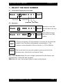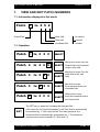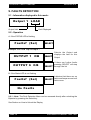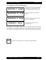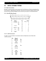
1
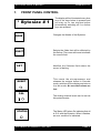
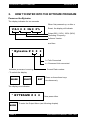
LIGHTING
BYTESIZE
483 / BIGTOP
User’s Manual
VERSION 8.13
REVISION 3 JANUARY 2001
DOCUMENT NO. 801_023_3002
BYTESIZE USER’S MANUAL
V E R S I O N 8.13
CONTACT DETAILS
Head Office
23-31 Fonceca Street, Mordialloc
Victoria 3195, Australia
Telephone: 61 3 9587 2555 - Facsimile: 61 3 9580 7690
Email: [email protected]
New South Wales
Unit 5, 31 Bridge Road,
Stanmore NSW 2048, Australia
Telephone: 61 2 9550 3955 - Facsimile: 61 2 9519 3977
No part of this document may be copied, duplicated, stored by any mechanism
including electronic or photographic and nor may it be revealed to any unauthorised
party without the express written permission of the owner of the copyright
All copies must include this notice.
BYTESIZE, I.D.S., I.D.S/ ULTRA, PHANTOM, FELIX, SAGE, DIMMASTER,
P AT C H M A S T E R , FA U LT M A S T E R , AT R I P L E X , AT R I P L E S I I AT R I P L E X
ULTRA, ARE TRADEMARKS OF BYTECRAFT PTY LIMITED
PAGE 2
COPYRIGHT BYTECRAFT 1992 - 2001
BYTESIZE USER’S MANUAL
V E R S I O N 8.13
Contents
Contact details ............................................................................................... 2
Table of Contents ........................................................................................... 3
Foreword......................................................................................................... 4
1. Front Panel Control .................................................................................. 5
2. How to Enter into the Bytesize Program ................................................ 6
3. Order of the Menus .................................................................................. 8
4. View Output Level, Level source and Override mode ........................ 10
5. Select the rack number .......................................................................... 13
6. Channel Patch ........................................................................................ 14
7. View and Edit Patch numbers ............................................................... 15
8. Proportional patch ................................................................................. 17
9. Faults Detection ..................................................................................... 18
10. View Incoming DMX Data....................................................................... 20
11. Curves menu ........................................................................................... 22
12. Presets Menu .......................................................................................... 24
13. Byte Tools Selections ............................................................................ 26
14. Programming the Bytesize .................................................................... 32
15. Preset Record Menu .............................................................................. 33
16. Time Record Menu ................................................................................. 35
17. The Play Mode ........................................................................................ 38
18. Preset Tools Menu ................................................................................. 42
19. Example of Programming Cue Sheets ................................................. 54
20. Some Examples of the Utilisation of the Bytesize .............................. 57
21. Data Connections ................................................................................... 66
C O P Y R I G H T B Y T E C R A F T 1 9 9 2 - 2001
PAGE 3
BYTESIZE USER’S MANUAL
V E R S I O N 8.13
FOREWORD
All the way through this manual, the “ ● ” shown on the LCD display indicates that the
value represented could be different to the one you actually read due to different settings
which may already be stored in the dimmer. This should not, we hope, unduly disturb
the comprehension of the operation of the Bytesize.
Please read this manual thoroughly before attempting to program the Bytesize.
PAGE 4
COPYRIGHT BYTECRAFT 1992 - 2001
BYTESIZE USER’S MANUAL
1.
V E R S I O N 8.13
FRONT PANEL CONTROL
* Bytesize # 1
The display will be illuminated every time
one of the keys below is pressed and
will stay on for two minutes before
automatically switching off if no further
keys are pressed.
MODE
Changes the Modes of the Bytesize.
SELECT
Selects the fields that will be affected by
the Set key. The cursor will move to indicate
the current field.
SET
Modifies the Selected field where the
cursor is flashing.
RESET
This resets the microprocessor and
releases the outputs locked in Override
mode, switches off the display and returns
it to idle mode. No recorded values are
lost.
=
CAL.
The Analog channel levels can be set via
this potentiometer.
=
STATUS
C O P Y R I G H T B Y T E C R A F T 1 9 9 2 - 2001
The Status LED when On indicates that all
is O.K. with the Bytesize. When it flashes,
an error condition is indicated.
PAGE 5
BYTESIZE USER’S MANUAL
2.
V E R S I O N 8.13
HOW TO ENTER INTO THE BYTESIZE PROGRAM
Power on the Bytesize
The display indicates for two seconds
When first powered up, or after a
V 8.3 Hz %
Reset, the display will indicate:
Output 50% (110V), 100% (240V)
Operating Frequency.
Software Version.
and then
* Bytesize # f = Felix Connected
c = Command Link connected.
Indicates processor is running
Current Rack number
- To unlock the display:
MODE
SELECT
SET
Press on these three keys
simultaneously
The display now indicates:
* BYTESIZE # MODE
PAGE 6
Now press either
To enter the Output Menu (see following chapter)
COPYRIGHT BYTECRAFT 1992 - 2001
BYTESIZE USER’S MANUAL
V E R S I O N 8.13
Or if the STATUS Led flashes
SELECT To enter the Fault Detection Menu (see relevant chapter for more
information).
C O P Y R I G H T B Y T E C R A F T 1 9 9 2 - 2001
PAGE 7
BYTESIZE USER’S MANUAL
V E R S I O N 8.13
3 - ORDER OF THE MENUS
* Bytesize # MODE
Output 1 = %
MODE
Output Mode
see Chapter 4
Rack DMX MODE
Select Rack # / DMX #
See Chapter 5
Patch to
MODE
Softpatch Dimmers
See Chapter 6
Propor@
MODE
Set Dimmer Level
See Chapter 7
Fa u l t s? (Sel)
MODE
Fault Detection
See Chapter 8
No DMX 512 Data
MODE
View Digital Data
See Note (1).
See Chapter 9
Curve 1 = MODE
Set Curves
See Chapter 10
Presets ? (Sel)
PAGE 8
MODE
Presets Menu
- Record Presets
- Record Time
- Record Sequence
- Preset Tools
See Chapter 11
COPYRIGHT BYTECRAFT 1992 - 2001
BYTESIZE USER’S MANUAL
B y t e To o l s ? ( S e l )
* Bytesize # V E R S I O N 8.13
MODE
Enable/Disable
- DMUX
- Felix
- Command Link
- Load fail
- Analog input
- Soft
- Driver
- Phase
- Filter
Store Backup
Restore Defaults
See Chapter 12
Return to the top menu
Note 1: This menu will not be displayed if the DMUX reading had been
disabled in the “Byte Tools”
C O P Y R I G H T B Y T E C R A F T 1 9 9 2 - 2001
PAGE 9
BYTESIZE USER’S MANUAL
V E R S I O N 8.13
4 - VIEW OUTDUT LEVEL, LEVEL SOURCE AND
OVERRIDE MODE
4.1 -Information displayed in this mode:
Output 1 = 2 5%eD
Output Number Field
or channel
Level Field
Source Field:
- A = Analog level
- B =Backup level
- C = Command link level
- D = DMX console level
- E = Test fade level
- F = Felix level
- O = Override level
- P = Preset level
Error Field:
— e = Softpatch error
See Note (1)
4.2 — Operation
Output 1 = %
Output 1 = %
SET
MODE
PAGE 10
Moves the cursor
from the output
SELECT field to the level
field.
Returns the cursor
to the
SELECT
output field.
This key will increase the output number if the cursor is in the Output
field. At Output 12, it will roll back to Output 1.
In the Level field, it will increase the intensity in 5% steps, starting from
00%. The letter on the right of the display will change to “O” (see above
for the meaning of all the letters). An output in “O” (Override) mode is
maintained at the level indicated as long as it is not unlocked.
There are two ways to unlock Outputs that are in “Override”:
1 - Increase the Output level until it exceeds “F”. The intensity is returned
to the level of the source that controls it at the time. The letter on the
right will change to indicate the source of the intensity. (See above for
the meaning of all the letters).
2 - Press on the RESET button.
- The Mode key will take you to the next menu at any time. (See section
Rack Number)
COPYRIGHT BYTECRAFT 1992 - 2001
BYTESIZE USER’S MANUAL
V E R S I O N 8.13
4.2.1 - Tip: When you set a level for an output in the Override mode, the numerically
following output selected will be set first at the level of the numerically preceeding
channel. The reason for this is to allow you to radiply set several Outputs in succession
at the same level.
4.2.2 - Example:
Set Output 1 through 4 to 15 %
Output 1 = %
SELECT
Output 1 = %
SET
Output 1 = 0 5%O
SET
Output 1 = 0 0%O
SET
Output 1 = 1 5%O
SELECT
Output 1 = 1 5%O
SET
Output 2 = %
SELECT
Output 2 = 0 0%O
SET
C O P Y R I G H T B Y T E C R A F T 1 9 9 2 - 2001
PAGE 11
BYTESIZE USER’S MANUAL
V E R S I O N 8.13
Output 2 = 1 5%O
SELECT
Output 2 = 1 5%O
SET
Output 3 = %
SELECT
Output 3 = 0 0%O
SET
Output 3 = 1 5%O
SELECT
Output 3 = 1 5%O
SET
Output 4 = %
SELECT
Output 4 = 0 0%O
SET
Output 4 = 1 5%O
4.3 - Note 1
Output 1 = 2 5%eD
The letter “e” will appear in the
error field if a softpatch error is
detected.
Assuming that the Bytesize is controlled by a lighting console producing 240
channels, if one softpatches any output to channels 241 or above, this error flag will
appear.
PAGE 12
COPYRIGHT BYTECRAFT 1992 - 2001
BYTESIZE USER’S MANUAL
V E R S I O N 8.13
5 - SELECT THE RACK NUMBER
5.1 - Information displayed in this mode:
Rack
0
Tens Field
1 DMX 0 0 1
SELECT
Units Field
Hundreds Tens Units
5.2 - Operation
Rack
Rack
SET
MODE
0
0
1 DMX 0 0 1
Moves the cursor from
SELECT the units field to the tens
field.
1 DMX 0 0 1
Press Select to move
SELECT the cursor to the DMX
section
This key will increase the selected field. If the value for the Units field
passes 9, the Tens field is automatically incremented by 1. The
maximum value selectable is 99 for a rack No. or 512 for DMX No.
This key will store the new rack number in memory and exit to the
following menu. (See Section on Channel Patch)
Note: Rack Number allows the user to assign a particular ID to the dimmer, (see
command link). It does NOT alter the patch!
DMX allows the user to set a base channel number for that dimmer.
C O P Y R I G H T B Y T E C R A F T 1 9 9 2 - 2001
PAGE 13
BYTESIZE USER’S MANUAL
6.
V E R S I O N 8.13
CHANNEL PATCH
The Patch Menu enables the user to assign outputs to channels that are not in default
sequence set via the DMX command.
PAGE 14
COPYRIGHT BYTECRAFT 1992 - 2001
BYTESIZE USER’S MANUAL
7.
V E R S I O N 8.13
VIEW AND EDIT PATCH NUMBERS
7.1 -Information displayed in this mode:
Patch
1 to2 5 2
OutputField
Units field
Tens field
Hundreds field
for control
channel
number
7.1- Operation
Patch to
Patch to
Patch to
Patch to
Patch to
SET
SELECT
SELECT
SELECT
Moves the cursor from the
Output field to the channel
control units field.
Moves the cursor from the
units field to the tens
field.
SELECT
Moves the cursor
from the tens field to the
hundreds field.
SELECT
Returns the cursor
from the hundreds field to
the Output field.
The SET key or wheel will increase the selected field.
If the value for the Units field passes 9, the Tens field is automatically
incremented by 1. If the value for the Tens field passes 9, the
Hundreds field is automatically incremented by 1. The maximum
channel value cannot exceed 512. See Note (1).
C O P Y R I G H T B Y T E C R A F T 1 9 9 2 - 2001
PAGE 15
BYTESIZE USER’S MANUAL
MODE
PAGE 16
V E R S I O N 8.13
Pressing mode will take you to the Proportional Patch Menu
COPYRIGHT BYTECRAFT 1992 - 2001
BYTESIZE USER’S MANUAL
8.
V E R S I O N 8.13
PROPORTIONAL PATCH
8.1 - Information displayed in this mode:
Propor1@ 9 0 %
Output Field
Channel
Proportion Field level or %
8.2- Operation
Propor@
Propor@
Propor@
SET
SELECT
SELECT
Moves the cursor from the
Output field to the
Proportion level Field.
SELECT
Returns the cursor from the
Proportion level Field to the
Output Field.
- This key will increase the output number if the cursor is the Output field.
At Output 12, it will roll back to Output 1.
- In the Proportion Field Level, it will increase the intensity in 10% steps,
starting from the last Proportion level set.
Use the SET key to alter the proportion level in 10% steps, or the wheel
in 1% steps.
8.1.1- WARNING: This very powerful feature allows the limitation of Output. If you
want to increase a proportion, you should always check the type of luminaries
connected to this output. We recommend that you label the relevant output to
clearly indicate the chosen setting.
MODE
Pressing mode will take you to the Faults Menu
C O P Y R I G H T B Y T E C R A F T 1 9 9 2 - 2001
PAGE 17
BYTESIZE USER’S MANUAL
V E R S I O N 8.13
9. FAULTS DETECTION
9.1 - Information displayed in this mode:
Output 1
LOA D
Output field
Fault Displayed
9.2 - Operation
A: If the STATUS LED is flashing
Faults? (Sel)
SELECT
Example: For a C/B Trip on output 1
OUTPUT 1
C/B
O U T P U T 6 C/B
SELECT
Selects the Output and
displays the fault for this
Output
If there are further faults
pressing SELECT will step
SELECT through the list
B: If the Status LED is not flashing
Faults? (Sel)
Indicates that there are no
SELECT faults and loops around until
faults occur.
N o Fa u l t s
9.2.1 - Note: The Fault Detection Menu can be accessed directly after unlocking the
Bytesize by pressing the Select key.
See Section on How to Unlock the Display
PAGE 18
COPYRIGHT BYTECRAFT 1992 - 2001
BYTESIZE USER’S MANUAL
V E R S I O N 8.13
9.3 - Example List of the Fault Messages
OUTPUT 1
L OA D
OUTPUT 8
C/B
OUTPUT 3
SCR
PHASE 5
FA I L
The Output 1 has no load connected to
its Output or the load is open circuit.
Oniy displayed if the Output is at 0%.
The Circuit Breaker for Output 8 is
tripped
The SCR or Opto coupling device for
Output 3 is damaged
The Phase for outputs 5-8 is not
supplying power
9.3.1 - Note: All the messages listed above can be transmitted to Bytecraft’s Computer
“Fault Master”. If this system is situated next to your lighting console, you will then be
able to monitor the complete dimming system whilst simultaneously running the show.
MODE
Pressing mode will take you to Viewing Incoming DMX Data
C O P Y R I G H T B Y T E C R A F T 1 9 9 2 - 2001
PAGE 19
BYTESIZE USER’S MANUAL
V E R S I O N 8.13
10. VIEW INCOMING DMX DATA
10.1 - Information displayed in this mode
D 5 1 2 A 0 0 1 = 00%
Data Type
Hundreds Field
Tens Field
Units Field
Incoming Level
10.1.1 - U.S.I.T.T. DMX Digital Transmission Display
D 5 1 2 A 0 0 1 = 00%
10.2 Operation
D 5 1 2 A 0 0 1 = %
D 5 1 2 A 0 0 1 = %
PAGE 20
SELECT
Moves the cursor from the
units field to the tens field.
COPYRIGHT BYTECRAFT 1992 - 2001
BYTESIZE USER’S MANUAL
D 5 1 2 A 0 0 1 = %
D 5 1 2 A 0 0 1 = %
V E R S I O N 8.13
Moves the cursor
from the tens
SELECT field to the
hundreds field.
Returns the cursor
SELECT from the hundreds field to
the unit field.
The SET key or wheel will increase or decrease the selected field.
SET
If the value for the Units field passes 9, the Tens field is automatically
incremented by 1. If the value for the Tens field passes 9, the
Hundreds field is automatically incremented by 1.
The Value shown next to the selected channel is the intensity sent
from the control desk at that time.
MODE
This key will quit the mode and take you to the following menu. See
Section on Curves.
10.2.1 Note 1: The maximum channel value cannot exceed 512.
10.2.2 Note 2: If DMX is turned off in the Byte Tools menu, the DMX data
displays will not be available.
C O P Y R I G H T B Y T E C R A F T 1 9 9 2 - 2001
PAGE 21
BYTESIZE USER’S MANUAL
V E R S I O N 8.13
11. CURVES MENU
11.1 - Information displayed in this mode:
Curve 1 = Output Field
Curve name:
The name displayed is
the curve selected at
this time.
11.2 — Operation
Curve 1 = SET
This key will increase the output number if the cursor is the Output
field. At Output 12, it will roll back to Output 1.
Curve 1 = SET
PAGE 22
Moves the cursor from the
SELECT Output field to the
Curve Field.
In the Curve Field, pressing this key will display all the curves that
are assignable one at a time.
Curve 1 = MODE
Press Select to enable
SELECT cursor on output field.
Returns the cursor from the
SELECT Curve Field to the Output
Field. The curve displayed is
then allocated to the Output.
The Mode key will take you to the next menu at any time.
See Section Preset Main Menu Selection.
COPYRIGHT BYTECRAFT 1992 - 2001
BYTESIZE USER’S MANUAL
V E R S I O N 8.13
11.3 - List of the Curves
Curve 1 = L i t e 3
Cur ve 1
=
110v
Curve 1 = U s e r 1
SELECT
Linear light, follow
the fader,
SET
This curve limits the
maximum output to
approx. 110v
SET
This curve can be
configured by the user.
Curve 1 = P h a s e
Phase timing linear.
Curve 1 = V o l t s
SELECT Volts Output Linear
Curve 1 = L i t e 1
SELECT
Curve 1 = N o D i m
SELECT triggers at 51%
Curve 1 = F l u r o
For use with fluorescent
SELECT tubes
Curve 1 = L i t e 2
C O P Y R I G H T B Y T E C R A F T 1 9 9 2 - 2001
Slow start fade
Static relay,
Very slow start, most of the
SELECT fade is in the 50-100%
Used for Mechanical
dimmers
PAGE 23
BYTESIZE USER’S MANUAL
V E R S I O N 8.13
12. PRESETS MENU
This is the main menu for the recording of Presets inside the Bytesize. In this chapter
we will deal only with the displays of the SubMenus pertaining to this mode. Each
SubMenu will be detailed later in this manual.
Note: If you do not need to program the Presets (which is often the case in “straight live
theatre” applications), do not press on the (SEL) key. It will save you reading the relevant
chapters.
All the facilities related to the programming of the Bytesize are greatly eased by using
Bytecraft’s proprietary “Felix” remote programming tool. (Please read the relevant manual
for further explanations).
12.1 - Operation
Presets ? (Sel)
RECORD (Sel/Set)
Displays the Record Preset
SELECT SubMenu
TIME (Sel/Set)
Displays the Time Preset
SELECT SubMenu
P L AY ( S e l / S e t )
Displays the Play Preset
SELECT SubMenu
TO O L S ( S e l / S e t )
Displays the Presets Tools
SELECT Configuration Submenu.
RECORD (Sel/Set)
Loops back to the Record
SELECT Preset SubMenu
PAGE 24
COPYRIGHT BYTECRAFT 1992 - 2001
BYTESIZE USER’S MANUAL
SET
MODE
V E R S I O N 8.13
This key will allow you to enter the displayed SubMenu.
When this key is depressed you will be returned to the
“Byte Tools” menu.
12.1.1 - A word of advice
The Presets recording feature of the Bytesize is extremely powerful and like everything
powerful it should be understood before attempting to use it. We suggest that, when
you require to program a Bytesize, you thoroughly preplan. At the end of this manual
are attached some suggested cuesheets which should be filled in before entering the
“Presets” SubMenus. It will save you both time and frustration.
C O P Y R I G H T B Y T E C R A F T 1 9 9 2 - 2001
PAGE 25
BYTESIZE USER’S MANUAL
V E R S I O N 8.13
13. BYTE TOOLS SELECTIONS
This menu is situated at the end of the loop of menus because it is used very rarely.
Nevertheless, it is the first menu that you should enter to verify the way in which the
Bytesize is configured.
13.1 - Operation
B y t e To o l s ? ( S e l )
D mux
(Set)
F e l i x (Set)
C Link
(Set)
SELECT Enter the Byte Tools Menu.
Displays the status of the
SELECT Dmux input.
SELECT Displays the status of the
Felix input.
SELECT
Displays the status of the
Command link input.
See note (5) below
L F a i l (Set)
SELECT Displays the status of the
A n a l o g (Set)
SELECT Displays the status of the
S o f t (Set)
Driver
(Set)
P h a s e (Set)
Load Fail Monitoring.
Analog input.
SELECT Displays the status of the
Soft Start feature
SELECT
Displays the status of the
Driver line Output
See Note (1) below
Displays the status of the
SELECT Phase Rotation. See Note
(5) below
PAGE 26
COPYRIGHT BYTECRAFT 1992 - 2001
BYTESIZE USER’S MANUAL
V E R S I O N 8.13
Filter % Left
SELECT Displays the amount of filter
New Backup (Set)
SELECT Selection. See Note (2)
life left. See Note (6) below
Record Backup Preset
below
D e f a u l t s( S e t )
Set Defaults menu
SELECT Selection. See Note (3)
below
D m u x ( S e t)
SET
SELECT Returns to the
top selection
This key will toggle between the ON mode and the OFF mode for the
selected option. When no ON or OFF modes are given as options then
please read the notes below for further explanation.
MODE
The Mode key will take you to the first menu at any time.
13.1.1 - Note1:
This selection is related to the “Presets” menu. It allows for the provision of a 5 Volts
reference to pin 3 of the DB25. This voltage is intended to generate an internal reference
to trigger the remote triggering function of the Bytesize.
C O P Y R I G H T B Y T E C R A F T 1 9 9 2 - 2001
PAGE 27
BYTESIZE USER’S MANUAL
V E R S I O N 8.13
Before this selection can be made available, the “C Link” Tools menu must be set to
OFF otherwise the following message is displayed:
D r i ve r i n U S E
Once the “C Link” is set to OFF, the following options are possible:
D r i ve r o n ( S e t )
D r i ve r o f f ( S e t )
SET
SET
Line 3 of the DB25
socket now transmits 5
Volts.
Line 3 of the DB25
socket does not transmit
5 Volts. An external
voltage reference must
be provided to trigger
presets.
13.1.2 -Note 2:
The Backup Preset is a lighting state which is only used when the Bytesize is
switched on and no external Control data is present. In this case, the levels
previously stored as a Backup Preset are now output and will remain valid until an
external control is applied to the Bytesize.
New Backup (Set)
Backup Done
SET
Record Backup Preset
Selection
The levels which were
present in the Bytesize
have been recorded in the
Backup Preset.
13.1.3.1— Tip: One of the uses of the Backup Preset is:
You record a lighting state in the dimmers which allows you to have some service light.
When you arrive in the theatre, you switch on the Mains to the dimmers and your
service lights appears on Stage. As soon as you walk into the control room, and switch
on the control desk, all the service lights will switch off and return control to the DMX
input as the Bytesize is now receiving input directly from the desk.
PAGE 28
COPYRIGHT BYTECRAFT 1992 - 2001
BYTESIZE USER’S MANUAL
V E R S I O N 8.13
13.1.4 — Note 3:
Defaults? (Set)
Defaults? Done
SET
Will set the Defaults in the
Bytesize. See Note (4.1)
Defaults accepted
When the Defaults are done, the following parameters are set:
The Rack number is returned to Rack 1. (Refer to Section Rack Number)
The Patch for the Outputs becomes 1:1 starting at channel 1 (Refer to Section Channel
Softpatch)
WARNING: Proportion for all the Outputs returns to FULL. (Refer to Section, Proportional
Patch)
The Curves are reset to “Lite 3”. (Refer to Section Curves)
The “Backup” Preset is recorded at 00%. (Refer to Section “Byte Tools”)
13.1.4.1 — Note 3.1:
Defaults? Denied
This message will appear if
you try to set Defaults whilst
the “Command Link” is
connected.
Either send the “Defaults” via the “Command Link” (please refer to the Fault Master,
Dim Master, Event Master Operator’s Manual for further information on this procedure)
or disconnect the “Command Link” cable before repeating this operation.
13.1.5 — Note 4:
C Link Denied
Indicates that the “Driver”
in the “Byte Tools” Menu is
ON. Switch it to OFF in
order to access the
“C Link” selection.
13.1.6 — Note 5:
The Bytesize is a purely digital dimmer. It calculates at the time it is switched on, the
proper phase rotation when this menu is set to AUTO. In case of poor mains
conditions, this automatic selection can be overridden as indicated below.
C O P Y R I G H T B Y T E C R A F T 1 9 9 2 - 2001
PAGE 29
BYTESIZE USER’S MANUAL
V E R S I O N 8.13
Displays the status of the
Phase Rotation. See Note 6
below
Phase (Set)
Phase Auto (Set)
SET
Sets the Phase Rotation to
Automatic mode.
Phase One
(Set)
SET
Forces the Phase Rotation to
Single phase mode.
Phase Fwd
(Set)
SET
Forces the Phase Rotation to
Forward mode.
P h a s e Rev ( S e t )
SET
Forces the phase rotation to
Reverse mode.
After this selection is made, it is necessary to RESET the dimmer.
13.1.7 - Note 6:
The Bytesize 483 is equipped with a fan which pumps air through the cooling fins to
maintain the SCR at a normal operating temperature. The air is filtered before entering
the dimmer. The filter has to be changed regularly to guarantee the maximum flow of
air.
A counter indicates the percentage of life left for this filter.
When the time arrives to change the filter this is indicated on the display and the
procedure indicated below shows how to reset the counter.
Filter % Left
Filter 50% Left
Replace Filter
PAGE 30
Displays the amount
of filter life.
Indicates that the filter
still has 50% of life left.
Indicates that the filter
has to be replaced.
COPYRIGHT BYTECRAFT 1992 - 2001
BYTESIZE USER’S MANUAL
V E R S I O N 8.13
Once the filter is changed, it is necessary to indicate to the Bytesize program that the
counter has to restart at 100%:
Replace Filter
SET
Press this key to reset the
counter to l00%.
Filter Time Cleared
This message indicates that
the counter has been reset.
C O P Y R I G H T B Y T E C R A F T 1 9 9 2 - 2001
PAGE 31
BYTESIZE USER’S MANUAL
V E R S I O N 8.13
14 - PROGRAMMING THE BYTESIZE
The Bytesize can be internally programmed to operate as a stand alone unit. All the
lighting cues are stored in the Bytesize and can alternatively be run in an automatic
mode, or triggered by various external stimuli such as time switches, tape recorders,
etc.
The Bytesize is supplied with Battery RAM: The Bytesize can store up to fifty Presets.
14.1 — Before starting:
This programming feature of the Bytesize means that this dimmer is potentially very
powerful. So, like every powerful program, a minimum of preplarining is necessary. To
guide you in this task, you will find attached at the end of this manual some examples
of cuesheets which will facilitate the easier planning of your task.
As you will notice, the first page of these Cuesheets is a reflection as to how the TOOLS
menu should be organised. This should be done first. If you follow this procedure
you will save yourself both time and frustration.
Even though the TOOLS menu is set at the end of the PRESETS Menu, (because it is
usually used once per programming session), we suggest that you enter it first to
configure the Bytesize for your specific application.
14.2 — In a nutshell:
The Bytesize can store up to 50 Presets. Each of these presets can be given a fade
time (from 0.1 second to 60 seconds). Each of these presets can be linked in sequences
and played in succession or looped through. The playback feature allows either local
start and automatic run and/or remote starts via the Analog Inputs of the dimmer.
Once the Bytesize is programmed, power can be switched off without the risk of losing
any information in the unit. The Bytesize will resume its operation upon power up in
exactly the same place it was before it was turned off.
PAGE 32
COPYRIGHT BYTECRAFT 1992 - 2001
BYTESIZE USER’S MANUAL
V E R S I O N 8.13
15. PRESET RECORD MENU
This menu allows the recording of light levels in the Bytesize internal Presets.
The recording of light levels in the Presets menu of the Bytesize is greatly eased by the
use of Bytecraft’s proprietary “Felix” remote controller, (for further explanation on this
device, please consult the “Felix” User’s Manual).
In order to record a Preset, you must bring up some lighting levels on the Bytesize. A
Preset will store the actual lighting levels at the time you record it. The source of the
levels is irrelevant. This means that you can build up your lighting levels with a DMUX
console, an Analog desk, the “Override Mode” (See the chapter on “Override Mode”)
and the “Felix” remote controller. All these sources of data can be operated concurrently.
Once your lighting levels have been set you can start recording the Presets. It is possible
to remain in this “Record Menu” and change the levels again to record further new
Presets.
15.1. - Operation
Re c o r d ( S e l / S e t )
PR 1
(Sel/Set)
SET
Enter the Record Preset
SubMenu.
SELECT Press Select to choose the
Preset number to Record.
P R 2 (Sel/Set)
Re c o r d
SET
(Set)
Press Set again to record
a new Preset.
SET
O ve r w r i t e
(Set)
Preset
Done
2
C O P Y R I G H T B Y T E C R A F T 1 9 9 2 - 2001
Press Set again to re-record
the old Preset.
This message will be
displayed for two seconds
to confirm the Record
action.
PAGE 33
BYTESIZE USER’S MANUAL
PR 3
V E R S I O N 8.13
The next Preset will then be
displayed ready to be
recorded.
(Sel/Set)
15.1.1 - Tip: If you have to record a Preset which is of a numerical order smaller
than the one currently displayed, then it is faster to exit to the top menu and then
re-enter instead of rolling through all the Preset numbers
15.1.2 - Example: If Preset 2 has just been recorded and you now want to record
Preset 1, follow this procedure:
PR 3
(Sel/Set)
Re c o r d ( S e l / S e t )
MODE
SET
This is the look of the
display once you have
recorded Preset 2. Press
MODE to return to the
Record Menu.
Enter the Record Preset
SubMenu.
Preset is now displayed.
PR 1
(Sel/Set)
Re c o r d
SET
Press SET to record
Press Set again to record
a new Preset 1.
(Set)
SET
O ve r w r i t e
Preset
(Set)
1 Done
P R 2 (Sel/Set)
PAGE 34
Press Set again to rerecord the old Preset 1.
This Message appears to
confirm the recording
After 2 seconds, display
will be ready for the next
recording.
COPYRIGHT BYTECRAFT 1992 - 2001
BYTESIZE USER’S MANUAL
V E R S I O N 8.13
16. TIME RECORD MENU
This menu allows for the recording of Times into the Bytesize internal Presets.
The recording of Times in the Presets of the Bytesize is greatly eased by the use of the
Bytecraft’s proprietary “Felix” remote controller (for further explanation on the device,
please consult the “Felix” User’s Manual).
From the front panel of the Bytesize, the recording of Times are limited to the fixed
values indicated below. However, using the “Felix” remote controller, any value in the
range of 0.1 second to 60 seconds is allowed.
The recording of Time in a Preset does not modify it’s lighting levels, thus consequently
changing of Times can be done as often as necessary.
16.1 - Operation
TIME
(Sel/Set)
SET
Enter the Record Time
SubMenu.
PR 0 T = . (Set)
SELECT Press SELECT to choose the
PR 1 T = . (Set)
SELECT The Time (00 . 0) shown is
PR 2 T = . (Set)
SELECT
T = . (Sel/Set)
SET
Preset number to time.
the Time currently recorded
to the indicated Preset.
Enter the Time selection
display
T = 00.0 (Sel/Set)
SELECT Press SELECT to choose the
T = 00.5 (Sel/Set)
SELECT
C O P Y R I G H T B Y T E C R A F T 1 9 9 2 - 2001
correct Time.
PAGE 35
BYTESIZE USER’S MANUAL
V E R S I O N 8.13
T = 0 1. 0 ( S e l / S e t )
SELECT
T = 03.0 (Sel/Set)
SELECT
T = 05.0 (Sel/Set)
SELECT
T = 10.0 (Sel/Set)
SELECT
T = 20.0 (Sel/Set)
SELECT
T = 30.0 (Sel/Set)
SELECT
T = 40.0 (Sel/Set)
SELECT
T = 60.0 (Sel/Set)
SELECT with your choice
E- 3 TI (Sel/Set)
PAGE 36
Press SET when satisfied
SELECT
This display indicates that
External Input 3 was set as a
Time Master. See Note 1.
COPYRIGHT BYTECRAFT 1992 - 2001
BYTESIZE USER’S MANUAL
E- 10 TI (Sel/Set)
Re c o r d
Time
2
(Set)
Done
PR 3 T =. (Set)
V E R S I O N 8.13
SET
The same thing for Input 10.
Press SET when satisfied
with your choice.
SET
Press SET again to Confirm
the recording.
This Message is displayed
to confirm the recording
After 2 seconds the display
look like this, and be ready
for the next recording.
16.1.1 - Note 1: If an Analog Input line has previously been configured as a Time
Master, this selection also becomes available in the Time choices. When a Time
Master is recorded to a Preset, the velocity of the Presets will depend on the position
of the fader connected to this Time Master controller line. If the fader is at 00% then
the velocity of the fade is instant, if the fader is at 100%, the velocity for the fade is at
the Time set for this Time Master. (see the “Analog Input Configuration” Menu for
further details).
16.1.2 - Tip: Whenever a Lighting Designer is undecided about the desired speed of
fades or chases, program the Presets to a Time Master and remote the speed control
to the panel where the triggering of the fades takes place. The operator will then be
able to modify the velocity of the fades “live”.
C O P Y R I G H T B Y T E C R A F T 1 9 9 2 - 2001
PAGE 37
BYTESIZE USER’S MANUAL
17.
V E R S I O N 8.13
THE PLAY MODE
This menu allows for the playing of a Preset or Sequence of Presets, in either manual,
automatic or remote modes.
A Sequence is made up of all the Presets which have been stored, and is played in
numerical order. Unused Preset numbers are skipped. The mode of operation of the
Sequence may vary greatly depending on setting of the parameters stored in the “Preset
Tools” menu. (Refer to the “Preset Tools” section for further details).
The programming of the Sequence and the Playback of the Bytesize is greatly eased
by the use of the Bytecraft’s proprietary “Felix” remote controller (for further explanation
on this device, please consult the “Felix” User’s Manual).
17.1 — Operation
PLAY
(Sel/Set)
A / P L AY O F F
(Set)
SET
Enter the Play Preset
SubMenu. See Note 1.
SELECT Automatic Play Menu.
See Section below.
E/ P L AY O F F
(Set)
SELECT External Play Menu. See
Section below.
PR 0
(Sel/Set)
SELECT
PR 1
(Sel/Set)
SELECT
PR 2
(Sel/Set)
SET
P L AY - P R
PAGE 38
2 10.0
Keep pressing SELECT
until you reach the Preset to
be played.
Press SET to play the Preset.
The Presets will now fade while
the time of the fade counts
down.
COPYRIGHT BYTECRAFT 1992 - 2001
BYTESIZE USER’S MANUAL
Preset
PR 2
2
V E R S I O N 8.13
Message indicating the
completion of the fade is now
displayed.
Done
(Sel/Set)
The display now restores to
waiting for the same Preset
to be replayed.
17.1.1 - Tip: If you have to play a Preset which is of a numerical value lower than the
one currently displayed, it is quicker to exit to the top menu and re-enter it instead of
rolling through all the Preset numbers
17.1.2 - Example: If Preset 2 has just been played and you now want to play Preset 1,
follow this procedure:
PR 2
(Sel/Set)
PLAY
(Sel/Set)
MODE
SET
This is the look of the
display once you have
played Preset 2. Press
MODE to return to the Play
Menu.
Enter the Play Preset
SubMenu.
A/P L A Y Off (Set)
SELECT Automatic Play Menu. See
E/P L A Y Of f (Set)
SELECT Section below.
Section below.
External Play Menu. See
PR 0
(Sel/Set)
SELECT
PR 1
(Sel/Set)
SET
P L AY - P R
1 10.0
C O P Y R I G H T B Y T E C R A F T 1 9 9 2 - 2001
Keep pressing SELECT
until you reach the Preset to
be played.
Press SET to play the
Preset.
The Preset will now fade
while the time of the fade
counts down.
PAGE 39
BYTESIZE USER’S MANUAL
Preset
PR 2
V E R S I O N 8.13
Message indicating the
completion of the fade is
now displayed.
1 Done
The display now restores to
waiting for the same Preset
to be replayed.
(Sel/Set)
17.2 - The Autoplay Mode
PLAY
(Sel/Set)
A/P L A Y Off (Set)
SET
Enter the Play Preset
SubMenu.
SET
Automatic Play Menu. Press
SET to enable this mode.
Automatic Play is now
enabled. Pressing SET
again would disable it.
A/P L A Y On (Set)
It is possible to see the progression of the sequence parameters on the LCD display
whilst the Sequence is running.
Automatic Play enabled.
A/P L A Y On (Set)
E/P L A Y Of f (Set)
P L AY - P R
PAGE 40
.
SELECT This now starts the
Sequence. Press SELECT
to skip to next menu.
SELECT
All the Presets played will
be shown with their fade
times as they are running.
COPYRIGHT BYTECRAFT 1992 - 2001
BYTESIZE USER’S MANUAL
V E R S I O N 8.13
17.3— The External Play Mode
PLAY
(Sel/Set)
A/P L A Y Off (Set)
E/P L A Y Of f (Set)
E/P L A Y On (Set)
SET
Enter the
SubMenu.
Play
Preset
SELECT Press Select to
skip the Automatic
Play Menu
SET
If External Play is disabled. Pressing SET
would enable it.
The External Play Mode enables the Bytesize to monitor the Analog Input lines and
perform the tasks for which they have been configured. (Refer to the “Analog Input
Configuration” Menu for further explanations).
Important Note: If you want the Bvtesize to maintain a lighting state to its Outputs
after leaving the “Play Preset” Menu, the “External Play” Mode must be enabled
otherwise the Outputs will be returned to the levels of the DMUX source.
17.4 — Note 1:
If you attempt to play Presets whilst the sequence is empty, you will be faced with the
following message.
PLAY
(Sel/Set)
No Preset Play
SET
Enter the
SubMenu.
Play
Preset
No Presets are recorded.
Go to the “Record Preset” Menu to create some Presets before proceeding with the
“Play Preset” Menu.
C O P Y R I G H T B Y T E C R A F T 1 9 9 2 - 2001
PAGE 41
BYTESIZE USER’S MANUAL
V E R S I O N 8.13
18. PRESET TOOLS MENU
This menu allows for the setting of the operational mode parameters of the Bytesize.
First the list of each mode in the menu is given. Each mode is then explained more fully
in order of appearance.
18.1 - Operation
TO O L S
(Sel/Set)
CLEAR
(Sel/Set)
SELECT below.
D/Time
(Sel/Set)
SELECT Section below.
Config
(Sel/Set)
SELECT Menu. See Section below
(Sel/Set)
(Sel)
SET
Enters the Presets Tools
Configuration Submenu.
Clear Menu. See Section
Default Time Menu. See
External Inputs Configuration
External Inputs Triggering
SELECT Type Selection. See Section
below.
SELECT Memory type. See Section
below.
( S e l / S e t )
( S e l / S e t )
Seq (Sel/Set)
SELECT
Fade type Configuration
Menu. See Section below.
Fade Time type
SELECT Configuration Menu.
See Section below.
Sequence type
SELECT Configuration Menu. See
Section below.
PAGE 42
COPYRIGHT BYTECRAFT 1992 - 2001
BYTESIZE USER’S MANUAL
Seq (Sel/Set)
V E R S I O N 8.13
SELECT Sequence link Configuration
Menu. See Section below.
CLEAR
(Sel/Set)
SELECT Returns to the Clear Menu.
See Section below.
MODE
SET
If this key is pressed at anytime during the operations listed above, you
will be returned to the “TOOLS” menu.
Pressing this key will enter the menu indicated on the display.
Once a menu has been entered, pressing the MODE key will return you to the title of
this menu.
C O P Y R I G H T B Y T E C R A F T 1 9 9 2 - 2001
PAGE 43
BYTESIZE USER’S MANUAL
V E R S I O N 8.13
18.2 - The Clear Menu
C lear (Sel/Set)
WARNING !!: Before operating this menu, think twice, it will erase all the contents of
all the Presets. However, it does not affect any other parts of the dimmer.
The “Backup Preset” is also not affected.
Clear all ( S e l / S e t )
Presets Cleared
Clear (Sel/Set)
SET
SET
For Safety’s Sake, You will
now have to press SET
again (this allows you to
change your mind!)
This operation will
-Erase all Presets
-Erase all Times
-Erase all the
Sequences. - Return the
external Config to its
original Setting.
If you do not press twice on SET
within three seconds, you are given
another chance and returned to the
Clear menu
For the rest of this section we will assume that you have Cleared all the Presets.
PAGE 44
COPYRIGHT BYTECRAFT 1992 - 2001
BYTESIZE USER’S MANUAL
V E R S I O N 8.13
18.3- The Default Time Menu
D/Time
(Sel/Set)
This menu allows you to set a Default time which will be recorded with each Preset.
It is intended to save you additional finger work for the more simple jobs. Let us say
for example, that you wish to record 10 presets which should all fade in 5 seconds,
you set this time of 5 seconds in this menu, and then every time you record a new
preset, it will be given this Default Time.
T = 03.0 (Sel/Set)
T = 05.0 (Sel/Set)
SET
SELECT
Press SET to enter the
menu.
Press SELECT to choose any
of the available Default
Times.
(All times are in seconds)
T = 10.0 (Sel/Set)
SELECT
T = 20.0 (Sel/Set)
SELECT
T = 30.0 (Sel/Set)
SELECT
T = 40.0 (Sel/Set)
SELECT
T = 60.0 (Sel/Set)
SELECT
T = 00.0 (Sel/Set)
SELECT
C O P Y R I G H T B Y T E C R A F T 1 9 9 2 - 2001
PAGE 45
BYTESIZE USER’S MANUAL
V E R S I O N 8.13
T = 00.5 (Sel/Set)
SELECT
T = 0 1. 0 ( S e l / S e t )
SELECT
Returns to top selection
T = 0 3. 0 ( S e l / S e t )
SELECT
T = 0 5. 0 ( S e l / S e t )
SELECT
Once you have found the Time from any of the above, it can be recorded as a Default
Time, thus.
RECORD (Set)
D/Time Done
SET
SET
For Safety’s Sake, You will
now have to press SET again
(this allows you to change
your mind!)
This operation now stores the
new Default Time selected
After 2 seconds the display
will show:
T = 0 3. 0 ( S e l / S e t )
PAGE 46
If you did not press twice on
SET you are given another
chance. If you pressed twice
you are taken to the following
menu.
COPYRIGHT BYTECRAFT 1992 - 2001
BYTESIZE USER’S MANUAL
V E R S I O N 8.13
18.4- The External Inputs Configuration Menu
The Bytesize is delivered equipped with twelve external input lines which are usually
used to fade up and down twelve Outputs. When the rack is used in the Preset Mode,
these twelve lines can be used differently.
Each input line can be configured in any one of the three following modes:
1 : Master mode. A line is now dedicated to a Preset. If a fader is connected to this line,
the complete Preset can be faded up or down. The time for this fade will depend on the
time recorded to this Preset.
2: Trigger mode. A line is now dedicated to a Preset. If for example a push-button is
connected to this line, the complete Preset can be triggered when FULL INTENSITY is
applied. (For the setting of the Control Voltage refer to the Technical Manual). This
Preset will fade up. Once it has reached its maximum intensity, the Bytesize will check
the Sequence Configuration to know how then to proceed (See the Sequence Section
for further details).
3 : Time Fader Mode. In this case, a Time is allocated to a line. A fader should now be
connected to this line. If the Presets are recorded using this fader, they will monitor this
line to know “in how much time” they should fade. Let’s assume that the Time allocated
is three seconds, if the Time Fader is at 100%, the Preset will fade in 3 seconds, if it is
at 50%, the Preset will fade in 1.5 seconds, if it is a 0%, the Preset will snap on.
Prior to being able to use this menu, you must have enabled the external Input inside
the “Byte Tools”, otherwise you will be faced with the following message:
Config not aval
Assuming everything is set properly we should be at:
Config (Sel/Set)
C O P Y R I G H T B Y T E C R A F T 1 9 9 2 - 2001
SET
Press SET to enter the Menu
PAGE 47
BYTESIZE USER’S MANUAL
V E R S I O N 8.13
The display is divided into three fields. The SELECT key will move the cursor from
Field to Field.
The external Input Field.
See Section below.
E - 01 MAS PR - 00
E - 01 M A S PR - 00
SELECT The Configuration Field.
E - 01 M A S PR - 00
SELECT
E - 01 MAS PR - 00
SELECT Field.
18.4.1
The Preset Field or Timer
Field. See Section below.
Back to the external Input
- The External Input Field
E - 02 MAS PR - 00
E - 03 MAS PR - 00
E - 03 M A S PR - 00
PAGE 48
See Section below.
SET
Choose the external
Input line.
SET
After 12, the external Input
line will roll back to 1
Press SELECT when
satisfied with your choice in
SELECT order to change to the next
field.
COPYRIGHT BYTECRAFT 1992 - 2001
BYTESIZE USER’S MANUAL
V E R S I O N 8.13
18.4.2 - The Configuration Field
Three different Configurations are available.
E - 03 MAS PR - 00
The Master Mode
E - 03 T R I PR - 00
SET
The Trigger Mode
E - 03 T I M T1 00.0
SET
The Timer Mode
E - 03 MAS PR - 00
SET
E - 03 MAS PR - 00
SELECT
Back to the top
Press SELECT when
satisfied with the choice.
17.4.3 - The Preset Field
E - 03 MAS PR - 01
E - 03 MAS PR - 02
SET
Choose the Preset to be
affected.
SELECT
Press SELECT when
satisfied with the choice.
There are cases where you wish to modify a Preset number which is less than the one
already selected. To save you rolling all the Presets up to the top, please follow this
example:
C O P Y R I G H T B Y T E C R A F T 1 9 9 2 - 2001
PAGE 49
BYTESIZE USER’S MANUAL
V E R S I O N 8.13
18.4.3.1 - Example
Assume you are reading the following display and you want to reset the Input Master 3
to Preset 1.
E - 03 MAS PR - 00
E - 03 MAS PR - 02
E - 03 T R I PR - 00
E - 03 T I M T1 00.0
E - 03 MAS PR - 00
E - 03 MAS PR - 00
E - 03 MAS PR - 01
SELECT
SET
SET
SET
Press SELECT to choose
the Configuration field.
Press SET to change the
field. Note that the number
now changes to 00.
Press SET to change the
field again.
Once more to return to
Master mode.
Press SELECT to change
SELECT to the Preset field.
SET
Press SET to choose
Preset 1.
That’s it. done.
PAGE 50
COPYRIGHT BYTECRAFT 1992 - 2001
BYTESIZE USER’S MANUAL
V E R S I O N 8.13
18.4.4- The Timer Field
This field appears only when the Configuration Field is at “TIM”
E - 03 T I M T100.0
E - 03 T I M T100.5
SET
E - 03 T I M T101.0
SET
E - 03 T I M T103.0
SET
E - 03 T I M T105.0
SET
E - 03 T I M T110.0
SET
E - 03 T I M T120.0
SET
E - 03 T I M T130.0
SET
E - 03 T I M T140.0
SET
E - 03 T I M T160.0
SET
Pressing SET will
increment the Timer field.
Press Select at any time to confirm your choice for any of these values.
C O P Y R I G H T B Y T E C R A F T 1 9 9 2 - 2001
PAGE 51
BYTESIZE USER’S MANUAL
V E R S I O N 8.13
18.6 - The Memory Configuration Menu
This Menu indicates how many presets are enabled.
18.7The Fade Type Menu
When running a sequence in the Bytesize, the Presets can either fade or snap from
one to the other.
The “Fade” mode is used to operate slow changes without the user noticing the lighting
changes. (Mood lighting, etc). The Time recorded with each Preset is the length of the
crossfade between Presets.
The “Wait” mode is used to achieve noticeable changes between Presets, to attract
attention from the user. (Sign lighting, etc). The Time Recorded with each Preset is the
Time this lighting state will stay on before “snapping” to the next one.
Fade (S e l / S e t )
SET
Fade Mode
Selection
Wait ( S e l/ S e t )
SET
Wait Mode
Selection
18.8 - The Sequence Type Mode
The sequence can be established in one of two ways, automatic or recorded. The
recorded sequence can only be built via the Bytecraft proprietary “Felix” remote control.
(Refer to the “Felix User’s Manual for further information).
When operating from the front panel the sequence is built automatically by the recording
of the Presets. Each time you record a new Preset, it is added to the sequence in
numerical order of Preset. For example: If you record Presets 1, 2, 8, 9, 12, the sequence
will play exactly that, it will not play any empty Preset in between. Now, if you come
back and record Preset 6, it will be added in the sequence which will then become 1, 2,
6, 8, 9, 12.
When the Bytesize reaches a stop in the sequence, it can either repeat the sequence
from the beginning if the menu has been set to “Seq Repeat”, or stop if the menu is set
to “Seq End”.
A stop in the Sequence can either be that the sequence is finished OR the Sequence
reaches an “END PRESET”. An “END PRESET” is a Preset recorded with a zero
(00.0) time.
18.8.1 - Note - An “END PRESET” is never played, the sequence stops on the
Preset immediately preceding it.
PAGE 52
COPYRIGHT BYTECRAFT 1992 - 2001
BYTESIZE USER’S MANUAL
V E R S I O N 8.13
18.8.1 - Note: Although an “END PRESET” is never played, it must have been recorded
with a lighting state in order to be valid. Otherwise it would be skipped and so
consequently the stop action would not be performed.
Seq End (S e l / S e t )
Seq Rpt ( S e l/ S e t )
SET
SET
Sequence End
selection.
Sequence Repeat
selection.
18.9 The Sequence Link Menu
The Sequence can be operated in one of two modes, the “Run Sequence” Mode or the
“Jog Seguence” Mode. In the first case, once the first Preset has been triggered by
either External or Local Trigger, the Sequence will continue with the remaining Presets
in the Sequence until it reaches a “STOP”. (See “Sequence Type” Mode for further
explanation on “STOP”). In the “Jog Sequence Mode”, the Bytesize will complete the
fade for the Preset triggered and wait for another trigger before proceeding to the next
Preset and so on until it reaches a “STOP”. Then the condition explained in the “Sequence
Type” mode will apply.
Run Seq (S e l / S e t )
SET
Run Sequence selection
Jo g S e q ( S e l / S e t )
SET
Jog Sequence selection
C O P Y R I G H T B Y T E C R A F T 1 9 9 2 - 2001
PAGE 53
BYTESIZE USER’S MANUAL
V E R S I O N 8.13
19. EXAMPLE OF PROGRAMMING CUE SHEETS
Over the following two pages is printed an example of a Cue Sheet. It will, we hope,
greatly assist you in the programming of the Bytesize.
Before starting to enter any cues in the dimmer, it may be prudent if you fill in these
forms. Go through the first page and set all the parameters in the “Byte Tools” Menu to
suit your needs, then proceed to the “Preset Tools” Menu.
Once this is done, write down on paper all the lighting states that you expect to use. If
the intensities can only be guessed at do not worry to much about their accuracy as
they can always be changed later on. What counts is the structure of the show.
When everything is to your satisfaction and clear on paper, start the programming
using either the Bytecraft’s proprietary “Felix” remote controller (for further explanation
on the device, please consult the “Felix” User’s Manual) or the front panel of the Bytesize.
PAGE 54
COPYRIGHT BYTECRAFT 1992 - 2001
BYTESIZE USER’S MANUAL
V E R S I O N 8.13
Project:
Date
BYTESIZE CUE SHEET
RACK #:
Dmux
Cmd Link
ANALOG
: [ON/OFF]
: [ON/OFF]
: [ON/OFF]
Felix
LoadFail
Soft
: ON/OFF]
: [ON/OFF]
: [ON/OFF]
AUTOPLAY
SEQUENCE
FADE
: [ON/OFF]
: [REP/END]
: [ON/OFF]
E/PLAY
SEQUENCE
DRIVER
: [ON/OFF]
: JOG/RUN]
: [ON/OFF]
CONFIGURATION OF THE EXTERNAL ANALOG INPUTS
EXTERNAL INPUT 1
EXTERNAL INPUT 2
EXTERNAL INPUT 3
MASTER
PRESET
MASTER
PRESET
MASTER
PRESET
TRIGGER
PRESET
TRIGGER
PRESET
TRIGGER
PRESET
TIMER
TIME
TIMER
TIME
TIMER
TIME
EXTERNAL INPUT 4
EXTERNAL INPUT 5
MASTER
PRESET
MASTER
PRESET
MASTER
PRESET
TRIGGER
PRESET
TRIGGER
PRESET
TRIGGER
PRESET
TIMER
TIME
TIMER
TIME
EXTERNAL INPUT 6
TIMER
TIME
EXTERNAL INPUT 7
EXTERNAL INPUT 8
EXTERNAL INPUT 9
MASTER
PRESET
MASTER
PRESET
MASTER
PRESET
TRIGGER
PRESET
TRIGGER
PRESET
TRIGGER
PRESET
TIMER
TIME
TIMER
TIME
TIMER
TIME
EXTERNAL INPUT 10
EXTERNAL INPUT 11
EXTERNAL INPUT 12
MASTER
PRESET
MASTER
PRESET
MASTER
PRESET
TRIGGER
PRESET
TRIGGER
PRESET
TRIGGER
PRESET
TIMER
TIME
TIMER
C O P Y R I G H T B Y T E C R A F T 1 9 9 2 - 2001
TIME
TIMER
TIME
PAGE 55
BYTESIZE USER’S MANUAL
RACK #
CHANNEL PATCH
PRESET #
ELAPS TIME
V E R S I O N 8.13
COMMENTS
1
2
3
4
5
6
7
8
9
10 11 12 MO EFFECTS
001
002
003
004
005
006
007
008
009
010
011
012
013
014
015
016
017
018
019
020
PAGE 56
COPYRIGHT BYTECRAFT 1992 - 2001
BYTESIZE USER’S MANUAL
V E R S I O N 8.13
20. SOME EXAMPLES OF THE UTILISATION OF
THE BYTESIZE
In this chapter, we will give some examples of challenges you may encounter, along
with a way of solving them. The Bytesize allows such a flexibility in programming that
we do not pretend to give you, in these pages, the best possible solution, but these
examples will certainly help you as a tutorial in developing your skills and finding new
ways of operating a real “Stand Alone” dimmer.
20.1 - Example 1: A Parking Project.
In a blind corridor (where no natural light is available) of an underground car park, you
have been asked to provide smart control of the lighting. When the delivery people
arrive they need a reasonable amount of light to carry their goods, but in order to save
power, the light must not stay on for an extended length of time. Since normal car park
customers are also using this corridor and there is an almost permanent level of traffic
it has been decided to maintain a lighting level at all times. Two lighting states have
been requested:
One at 90% (very bright but still saving lamp life) and one very dim at 30% (but still
bright enough to see). When initiated the bright state will fade up in three seconds,
stay on for 60 seconds, then fade back down to the dim state over 10 seconds. Several
control panels, each of which could be, for example, a simple push button, movement
detector, or an infrared beam, must be positioned at different locations along this corridor.
20.1.2 — Solution
We will have to provide control panels in several positions along the corridor. On each
control panel we will install:
A “Normally Open” Push button labeled “LIGHTS ON”.
The “LIGHTS ON” control must be connected to Analog Input 1.
We have chosen the following Dimming Output numbers:
Outputs 1 through 4 = Corridor lights
Every time one of the switches is depressed, the lights will fade up to their high intensity.
If any of the switches are depressed during the bright period, the bright state will remain
up for another minute, then fade back to the low level state.
Now, if you read the following two cue sheets and program the dimmer accordingly, you
will see how this problem has been solved.
C O P Y R I G H T B Y T E C R A F T 1 9 9 2 - 2001
PAGE 57
BYTESIZE USER’S MANUAL
V E R S I O N 8.13
Project: Parking Corridor
Date 23/11/99
BYTESIZE CUE SHEET
RACK #: 1
Dmux
Cmd Link
ANALOG
: [ /OFF]
: [ /OFF]
: [ON/
]
Felix
LoadFail
Soft
:
/OFF]
: [ON/
]
: [ON/
]
AUTOPLAY
SEQUENCE
FADE
: [ON/
]
: [
/END]
: [ON/
]
E/PLAY
SEQUENCE
DRIVER
: [ON/
]
:
/RUN]
: [ON/OFF]*
CONFIGURATION OF THE EXTERNAL ANALOG INPUTS
EXTERNAL INPUT 1
PRESET
TRIGGER PRESET
TIME
EXTERNAL INPUT 4
MASTER
PRESET
TRIGGER PRESET
TIMER
TIME
EXTERNAL INPUT 7
MASTER
PRESET
TRIGGER PRESET
TIMER
TIME
EXTERNAL INPUT 2
MASTER
PRESET
TRIGGER PRESET
TIMER
TIME
EXTERNAL INPUT 5
MASTER
PRESET
TRIGGER PRESET
TIMER
TIME
EXTERNAL INPUT 8
MASTER
PRESET
TRIGGER PRESET
TIMER
TIME
EXTERNAL INPUT 3
MASTER
PRESET
TRIGGER PRESET
TIMER
TIME
EXTERNAL INPUT 6
MASTER
PRESET
TRIGGER PRESET
TIMER
TIME
EXTERNAL INPUT 9
MASTER
PRESET
TRIGGER PRESET
TIMER
TIME
EXTERNAL INPUT 10
EXTERNAL INPUT 11
EXTERNAL INPUT 12
MASTER
MASTER
MASTER
PRESET
TRIGGER PRESET
TIMER
TIME
PRESET
TRIGGER PRESET
TIMER
TIME
PRESET
TRIGGER PRESET
TIMER
TIME
*This setting depends where the “Control Voltage” is sourced, (refer to the Technical
Manual and “Driver paragraph in the “Byte Tools” menu for futher information)
PAGE 58
COPYRIGHT BYTECRAFT 1992 - 2001
BYTESIZE USER’S MANUAL
V E R S I O N 8.13
Project: Parking Corridor
RACK #
CHANNEL PATCH
PRESET #
ELAPS TIME
Date 23/11/99
COMMENTS
1
2
3
4
5
6
7
8
9
10 11 12 MO EFFECTS
001
00:00
03.0
90 90 90 90
Fade up
002
00:03
60.0
90 90 90 90
Bright Cue
003
01:03
20.0
30 30 30 30
Dim Cue
004
01:23
00.0
30 30 30 30
“Stop Cue”
005
006
007
008
009
010
011
012
013
014
015
016
017
018
019
020
C O P Y R I G H T B Y T E C R A F T 1 9 9 2 - 2001
PAGE 59
BYTESIZE USER’S MANUAL
V E R S I O N 8.13
Project: Parking Corridor
Date: 23/11/99
20.2- Example 2: A Museum Exhibition
In a Museum, the Sculpture Gallery requires a lighting animation so as to enhance a
new exhibit.
Five statues are displayed scattered in an exhibition room. This room receives a large
quantity of natural light through large windows. Each statue has to be highlighted in
turn for a period which could be changed remotely and ranging from 5 seconds to 40
seconds. The cycle must be constant during the opening hours of the Museum. The
lighting animation starts in the morning and finishes late at night. When night comes,
the lighting levels for the statues have to be decreased to take account of the lack of
daylight (during the day the light levels have to be high to be noticed, at night they have
to be reduced to avoid a blinding effect), at the same time a general lighting state has
to be created for the safe movement of the visitors to the gallery.
The controls for the lighting animation must be operated from an office in the entrance
of the Museum. The operator must be able to select:
- The Day animation,
- The Night animation,
- Switch off the animations,
- Control the speed of the animations.
19.2.2 - Solution
A control panel will have to be manufactured on which are mounted the following:
- A “Normally open” Push button labeled “DAY”.
- A “Normally open” Push button labeled “NIGHT”.
- A “Normally open” Push button labeled “OFF”.
- A Potentiometer labeled “SPEED”.
The “DAY” control must be connected to Analog Input 1.
The “NIGHT” control must be connected to Analog Input 2.
The “OFF” control must be connected to Analog Input 3.
The “SPEED” control must be connected to Analog Input 4.
We have chosen the following Dimmer Output numbers:
Output
Output
Output
Output
Output
1=
2=
3=
4=
5=
Statue
Statue
Statue
Statue
Statue
1
2
3
4
5
Outputs 6 through 10 are for general lighting.
Now, if you read the following two cue sheets and program the dimmer accordingly, you
will see how this problem may be solved.
PAGE 60
COPYRIGHT BYTECRAFT 1992 - 2001
BYTESIZE USER’S MANUAL
V E R S I O N 8.13
Project: Statue Exhibition in a Museum
Date 23/11/99
BYTESIZE CUE SHEET
RACK #: 1
Dmux
Cmd Link
ANALOG
: [ /OFF]
: [ /OFF]
: [ON/
]
Felix
LoadFail
Soft
AUTOPLAY
SEQUENCE
FADE
: [ON/
: [REP/
: [ON/
E/PLAY
: [ON/
]
SEQUENCE :
/RUN]
DRIVER
: [ON/OFF]*
]
]
]
: [ /OFF]
: [ON/
]
: [ON /
]
CONFIGURATION OF THE EXTERNAL ANALOG INPUTS
EXTERNAL INPUT 1
TRIGGER
PRESET 1
EXTERNAL INPUT 4
EXTERNAL INPUT 2
TRIGGER
PRESET 7
EXTERNAL INPUT 5
MASTER
PRESET
TRIGGER PRESET
TIMER
TIME 40.0
EXTERNAL INPUT 7
MASTER
PRESET
TRIGGER PRESET
TIMER
TIME
TIMER
TIME
EXTERNAL INPUT 8
MASTER
PRESET
TRIGGER PRESET
TIMER
TIME
EXTERNAL INPUT 3
TRIGGER PRESET 13
EXTERNAL INPUT 6
MASTER
PRESET
TRIGGER PRESET
TIMER
TIME
EXTERNAL INPUT 9
MASTER
PRESET
TRIGGER PRESET
TIMER
TIME
EXTERNAL INPUT 10
EXTERNAL INPUT 11
EXTERNAL INPUT 12
MASTER
MASTER
MASTER
PRESET
TRIGGER PRESET
TIMER
TIME
PRESET
TRIGGER PRESET
TIMER
TIME
PRESET
TRIGGER PRESET
TIMER
TIME
*This setting depends on where the “Control Voltage” is sourced, (refer to the “Driver”
Paragraph in the “Byte Tools” menu for further information)
C O P Y R I G H T B Y T E C R A F T 1 9 9 2 - 2001
PAGE 61
BYTESIZE USER’S MANUAL
V E R S I O N 8.13
Project: Statue Exhibition in a Museum
RACK #
CHANNEL PATCH
PRESET #
ELAPS TIME
Date 23/11/99
COMMENTS
1
2
3
4
5
6
7
8
9
10 11 12 MO EFFECTS
001
Timer4 90
Day Stat 1
002
Timer4
003
Timer4
004
Timer4
005
Timer4
90
Day Stat 5
006
00.0
90
“Stop”
007
Timer4 70
008
Timer4
009
Timer4
010
Timer4
011
90
Day Stat 2
90
Day Stat 3
90
Day Stat 4
40 40 40 40 40
NIGHT 1
40 40 40 40 40
NIGHT 2
40 40 40 40 40
NIGHT 3
40 40 40 40 40
NIGHT 4
Timer4
70 40 40 40 40 40
NIGHT 5
012
00.0
70 40 40 40 40 40
“Stop”
013 (*)
03.0
1
OFF STATE
014 (**)
00.0
1
“Stop”
70
70
70
015
016
017
018
019
020
* To ensure that Preset 13 is a blackout, you must record one Output at 1%,
otherwise this Preset would not be played.
** Even though a “STOP PRESET” is never played, it must contain at least one level
to operate properly.
PAGE 62
COPYRIGHT BYTECRAFT 1992 - 2001
BYTESIZE USER’S MANUAL
V E R S I O N 8.13
20.3Example 3: A Nursing Home Project
A building complex for intellectually impaired people consists of several pavilions. Each of
these pavilions has 5 bedrooms and an attendant’s office. The attendant’s office is occupied
only during working hours, from 8 AM to 10 PM. It has been decided that each occupant of
a bedroom will have a control panel consisting of two push buttons next to their bed, so as
to switch the lights in their respective rooms either ON of OFF. The attendant must also be
able, from his office, to switch all the lights in all the bedrooms either ON or OFF at specific
times, depending on the activity in the pavillion. Finally, he must have control of the intensity
of the lights in the corridor which links his office to all of the bedrooms.
19.3.1 - Comments on this task.
We are facing the difficult task of controlling the lights in one area without disturbing any of
the others. It is probably the trickiest work you can ask a lighting controller to operate.
In this case we will have to use the Bytecraft’s proprietary “Felix” remote controller to program
the “MOVE PRESETS”.(Refer to the “Felix” User’s Manual for further information)
19.3.2 - Solution:
We will have to provide at the head of each bed a control panel with:
- A “Normally open” Push button labeled “LIGHTS OFF”.
- A “Normally open” Push button labeled “LIGHTS ON”.
A control panel will be manufactured for the office on which will be installed:
- A “Normally open” Push button labeled “BED ROOMS ON/OFF”
- A Potentiometer labeled “CORRIDOR”.
The “LIGHTS ON” for Bedroom 1 will be connected to Analog Input 1.
The “LIGHTS OFF” for Bedroom 1 will be connected to Analog Input 2 and so on for all of
the Bedrooms.
The “BEDROOMS ON/OFF” will be connected to Analog Input 11
The “CORRIDOR” control must be connected to Analog Input 12. We have chosen the
following Dimming Output numbers:
Output 1 = Bedroom 1
Output 2 = Bedroom 2
Output 3 = Bedroom 3
Output 4 = Bedroom 4
Output 5 = Bedroom 5
Outputs 6 through 10 for the Corridor
Now, if you read both of the following two cue sheets and program the dimmer accordingly,
you will see how this problem may be solved.
C O P Y R I G H T B Y T E C R A F T 1 9 9 2 - 2001
PAGE 63
BYTESIZE USER’S MANUAL
V E R S I O N 8.13
Project: A Nursing Home
Date 23/11/99
BYTESIZE CUE SHEET
RACK #: 1
Dmux
Cmd Link
ANALOG
: [ /OFF]
: [ /OFF]
: [ON/
]
FELIX
LOADFAIL
Soft
: ON/
: [ON/
: [ON/
AUTOPLAY
SEQUENCE
FADE
: [ON/
: [REP
: [ON/
E/PLAY
SEQUENCE
DRIVER
: [ON/
]
: JOG/
]
: [ON/OFF]*
]
]
]
]
]
]
CONFIGURATION OF THE EXTERNAL ANALOG INPUTS
EXTERNAL INPUT 1
TRIGGER
PRESET 1
EXTERNAL INPUT 4
TRIGGER
PRESET 4
EXTERNAL INPUT 7
TRIGGER
PRESET 7
EXTERNAL INPUT 10
EXTERNAL INPUT 2
TRIGGER
PRESET 2
EXTERNAL INPUT 5
TRIGGER
PRESET 5
EXTERNAL INPUT 8
TRIGGER
PRESET 8
EXTERNAL INPUT 11
EXTERNAL INPUT 3
TRIGGER
PRESET 3
EXTERNAL INPUT 6
TRIGGER
PRESET 6
EXTERNAL INPUT 9
TRIGGER
PRESET 9
EXTERNAL INPUT 12
MASTER PRESET 12
TRIGGER PRESET 10
TRIGGER PRESET 11
*This setting depends where the “Control Voltage”is sourced, (refer to the “Driver”
Paragraph in the “Byte Tools” menu for further information)
PAGE 64
COPYRIGHT BYTECRAFT 1992 - 2001
BYTESIZE USER’S MANUAL
V E R S I O N 8.13
Project: A Nursing Home
RACK #
CHANNEL PATCH
PRESET #
ELAPS TIME
Date 23/11/99
COMMENTS
1
2
3
4
5
6
7
8
9
10 11 12 MO EFFECTS
001
00.5
90
*
ROOM 1 ON
002
00.5
*
ROOM 1 OFF
003
00.5
*
ROOM 2 ON
004
00.5
*
ROOM 2 OFF
005
00.5
90
*
ROOM 3 ON
006
00.5
90
*
ROOM 3 OFF
007
00.5
40 40 40 40 40
*
ROOM 4 ON
008
00.5
40 40 40 40 40
*
ROOM 4 OFF
009
00.5
40 40 40 40 40
*
ROOM 5 ON
010
00.5
1
*
ROOM 5 OFF
011
00.5
90 90 90 90 90
All ON
012
00.5
1
1
1
1
1
“All OFF”
013
00.0
1
1
1
1
1
“Stop”
014 (**)
01.0
90
90
90
70
70
70
90 90 90 90 90
Corridor
015
016
017
018
019
020
* The “MOVE PRESETS” have to be programmed via the “Felix” remote controller for
the channels indicated with a level.
C O P Y R I G H T B Y T E C R A F T 1 9 9 2 - 2001
PAGE 65
BYTESIZE USER’S MANUAL
V E R S I O N 8.13
21. DATA CONNECTIONS
21.1 Data Connections
In order to communicate to the external world, the Bytesize is fitted as standard with a
D25 connector. Depending on the model, some other connectors might be fitted. Please
inquire with your Bytecraft Agent if the connector you expect is not detailed below.
21.1.1 Sub D25 Way Female
13 12 11 10
9
8
7
6
5
4
3
2
1
25 24 23 22 21 20 19 18 17 16 15
Pin
1
2
3
4
5
6
7
8
9
10
11
12
13
Signal
Ground
Command Rx+
“
“
“
Pin
14
15
“
“
16
“
“
3
Tx+
Tx-
17
18
“
“
4
“
“
“
“
“
“
“
“
5
6
7
8
“
“
9
“
“
19
DMUXA Rx+
20
21
Rx-
22
Rx+
Rx-
23
24
25
‘’
Felix
“
Ground
NC
Signal
Analog Ch.1
Rx-
Ground
“
14
2
“
10
“ 11
“
“
12
21.1.2 - JAE Connectors
In order to communicate to the external world, the Bytesize can be fitted with
a JAE connector.
Pin
1
2
3
4
5
6
7
8
9
10
11
12
13
14
PAGE 66
Signal
DMUXA
DMUXA
CMD
Ground
Rx+
RxRx-
CMD
Ground
Ground
Rx+
CMD
Ground
Felix
CMD
Felix
TxRxTx+
Rx
COPYRIGHT BYTECRAFT 1992 - 2001
BYTESIZE USER’S MANUAL
V E R S I O N 8.13
21.1.3 XLR 5 pins
In order to communicate to the external world, the Bytesize can be fitted with XLR
connectors. The wiring for these connectors respects the USITT standard. As a reminder
these connections are given below:
Pin
1
2
3
4
5
21.3 - USITT, RS-485 Standard
Signal
Ground
DMUXA
DMUXA
RxRx+
DMX 512 uses USITT RS-485 type differential line drivers and receivers. Typically in
DMUX lighting control applications, one line transmitter in the control desk feeds several
receivers in the dimmers.
The following points should be noted:
Maximum cable length 1.5 Km,
Termination resistor MUST be installed.
Balanced twisted pair shielded cable must be used.
Signal polarity must be observed ie Data+ to Data+, Data- to Data-.
Maximum 32 devices on any one transmission line.
C O P Y R I G H T B Y T E C R A F T 1 9 9 2 - 2001
PAGE 67