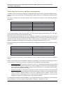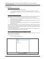
1
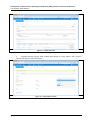
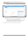
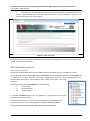
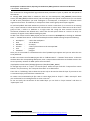
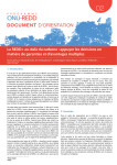
Ministry of Forests and Soil Conservation REDD Forestry and Climate Change Cell Development of a Measurement, Reporting and Verification (MRV) System for Emissions and Removals Contract No.: FCPF/REDD/S/QCBS-7 Working paper N.9 IT PLATFORM USER MANUAL AGRICONSULTING S.p.A. Via Vitorchiano, 123 – 00189 Rome, ITALY Development of a Measurement, Reporting and Verification (MRV) System for Emissions and Removals IT PLATFORM - USER MANUAL The contents of this publication are the sole responsibility of Agriconsulting S.p.A and MRV Team and can in no way be taken to reflect the views of the Nepal Ministry of Forests and Soil Conservation REDD and Climate Change Cell This publication is a property of REDD-Forestry and Climate Change Cell and is part of the MRV project funded by the World Bank. We would like to thank the whole REDD Cell Staff, in particular: Mr. Resham Bahadur Dangi, Chief, REDD Cell; Mr. Shree Krishna Gautam, REDD Cell focal point; Dr. Narendra Chand, Policy and Program Planning Officer, REDD Cell who provided insight and expertise that greatly assisted the project Authors: Mr. Antonio Marzoli Mr. Alberto Laurenti Mr. Davide Malpassini Mr. Daniele Macci Mr. Alessandro Di Stefano Mr. Virgilio Audisio Agriconsulting S.p.A. Page i Development of a Measurement, Reporting and Verification (MRV) System for Emissions and Removals IT PLATFORM - USER MANUAL List of Acronyms DNS : Domain Name System TCP : Transmission Control Protocol IP : Internet Protocol IP Address : Internet Protocol Address AJP : Apache JServ Protocol FTP : File Transfer Protocol PC : Personal Computer DFO : District Forest Office DB : Database GIS : Geographic information system MRV : Measuring, Reporting and Verifying NFMS : National Forest Monitoring Systems PFSF : Pilot Forest Survey Form CSMF : Carbon Stock Measurement Form Agriconsulting S.p.A. Page ii Development of a Measurement, Reporting and Verification (MRV) System for Emissions and Removals IT PLATFORM - USER MANUAL Connecting to the server and basic management IT platform (the set of software configured / developed specifically for the project and the web portal) is hosted on a Linux virtual machine running CentOS 6.5 64bit, made by the virtualization software Virtual Box 4.3. The virtual machine has network interface eth0 configured according to the following network parameters: Parameter IP Address Subnet mask Gateway Primary D.N.S. Secondary D.N.S. Configuration 172.16.80.153 255.255.0.0 172.16.10.56 172.16.10.1 172.16.10.2 In the virtual machine, there are two users: mrv_user and the system administrator root. The login password for both these utilities are agriconsulting. The virtual machine is running on the server "physical" provided for the project. The server uses the Linux operating system, the distribution CentOS 6.5 64bit. On the server there are two users: mrv_user and the root user. The login password for both of these utilities is agriconsulting. The virtualization software VirtualBox 4.3 running the virtual machine is configured with the user mrv_user. The physical server has a network interface eth0 that is configured according to the following network parameters: Parameter IP Address Subnet mask Gateway Primary D.N.S. Secondary D.N.S. Configuration 172.16.80.150 255.255.0.0 172.16.10.56 172.16.10.1 172.16.10.2 The eth1 interface of the server is not configured, it can be used to connect the server to a different subnet. Access to the portal, and thus to different software of IT platform, is possible by connecting the servers on the network. To do this it is necessary to follow one of the following operating modes: Single connection: it is necessary connect the server to a PC through crossover ethernet cable and configure the network card of the PC so that it appears as to be in the same subnet as the server (172.16.xx.xx static IP address, subnet mask and 255.255 .0.0). IT platform will be visible only to the PC connected to the server; Multiple connection: it is necessary to connect the server and the local PC to a hub or Ethernet switch, set up the network adapters of the local PC so that it appears in the same subnet as the server, to avoid IP address conflicts. In this way, IT platform will be visible to all PC on the network. If the pc undertakings have a second network interface (ethernet or wi-fi) you can configure it so that as to connect the PC to the corporate network. For changing the settings of network adapters, you should refer with work instructions for the operating system running on the client machine (eg Windows XP, Windows 7, Windows 8, Linux). Agriconsulting S.p.A. Page 1 Development of a Measurement, Reporting and Verification (MRV) System for Emissions and Removals IT PLATFORM - USER MANUAL If needed, you can work on the server machine or virtual machine without have physical access to server. Specifically: Connection by Linux environments Open a shell command bash and enter the command: ssh <utente>@172.16.80.150, to connect to the server machine with the user <user> ssh <utente>@172.16.80.153, to connect to the virtual machine of IT platform with users <user>. Connection by Windows environments On Windows you need to download the accessories software to operate from remote systems provided. Below is a list of recommended software and described in the following pages: WinSCP (http://winscp.net/eng/index.php): useful to move and / or copy files from / to your local PC to / from the remote; PuTTY (http://www.chiark.greenend.org.uk/~sgtatham/putty/download.html): used to open remote command shell; Xming (http://sourceforge.net/projects/xming/): X11 server to run graphical applications locally on the server. The installation of WinSCP and PuTTY are considered essential while Xming is optional and useful only if you want to run graphical applications remotely on the server. In the following we will consider two typical use cases of the proposed software, assuming that on the client is installed as a Windows 7 operating system. For more information about the use of these software please refer to the documentation consulted and / or downloaded at the website indicated above. Access to / editing remote files on the virtual machine of IT platform Situation: access to the virtual machine (172.16.80.153) to copy or modify files in the home mrv_user directory using WinSCP; Steps to follow to complete the task: o Run the programm WinSCP (figura 1); Figure 1 – Running WinSCP Agriconsulting S.p.A. Page 2 Development of a Measurement, Reporting and Verification (MRV) System for Emissions and Removals IT PLATFORM - USER MANUAL o Once you start the program, create a new connection and fill the required fields with the network parameters of the virtual machine (Figure 2) you can save the connection settings for future sessions of work without the need to recompile the required information. When done, press the Login button. Figure 2 – Connecting to server o The interface of software will be presented in two sections: on the left you will see the files in the local PC and on the right those on the remote server (Figure 3). Now you can move to the desired folder on the server, in this example / home / mrv_user, and copy and / or edit the files. Figure 3 – Local Files (left) and remote files (right) Agriconsulting S.p.A. Page 3 Development of a Measurement, Reporting and Verification (MRV) System for Emissions and Removals IT PLATFORM - USER MANUAL o In Figure 3 the button, that allows you to run PuTTY directly into WinSCP without making a new connection, it is highlighted in red. The Linux shell terminal will be open to the same server that is connected to WinSCP (Figure4).. In order to perform the operation correctly, you must first configure the path where the application is installed. To do this, open the menu Options \ Preferences, select the menu item Integrations \ Applications; fill in the field "Path PuTTY" indicating the location of the file putty.exe within your system. Select the option “Open Telnet sessions in PuTTY for FTP sessions”. Confirm the changes to the settings. Figure 4 – Running PuTTY from WinSCP Agriconsulting S.p.A. Page 4 Development of a Measurement, Reporting and Verification (MRV) System for Emissions and Removals IT PLATFORM - USER MANUAL Running remotely the virtual machine manager Situation: Using PuTTY to remotely open the graphical manager of the virtual machine (Virtual Box) on the server: Steps to follow to complete the task: o Run the Xming server, answer yes to any requests of the operating system to allow network access to the software. Make sure that the application is running on by identifying the icon in the Windows system tray; o Run PuTTY; o Configure PuTTY to connect to physical server (Figure 5A) and enable forwarding of graphics calls to the local X11 server (Figure 5B); Figure 5A (on the left) e 5B (on the right) Agriconsulting S.p.A. Page 5 Development of a Measurement, Reporting and Verification (MRV) System for Emissions and Removals IT PLATFORM - USER MANUAL o Make the connection by pressing the "Open"; o Enter the user's login credentials of mrv_user ; o From the command prompt, run the command: virtualbox o You will then see locally the screenshot of the graphical manager of Virtual Box (Figure 6), from which you can graphically manage the virtual machine on which you are running IT platform. Figure 6 – Graphical manager of Virtual Box The virtual machine running on the user mrv_user of the "physical" server it is configured to auto-start on boot of the server and it is automatically closed when turning off the server through the halt command or equivalent; it is not necessary any operation of start / stop of virtual machine. Should it be necessary to stop or restart the virtual machine manually, you can run or graphically enter to the operator (described above) or run the following commands from a remote terminal as user mrv_user: Poweroff: VBoxManage controlvm "MRV Test" poweroff Restart: VBoxManage controlvm "MRV Test" reset Start: VBoxManage startvm "MRV Test" --type headless To check the list of running virtual machine, you can run the command: VBoxManage list runningvms. For a comprehensive guide of these commands to manage remotely virtual machines, refer to the manual of virtualization software Virtual Box, available at the web: https://www.virtualbox.org/wiki/Documentation Agriconsulting S.p.A. Page 6 Development of a Measurement, Reporting and Verification (MRV) System for Emissions and Removals IT PLATFORM - USER MANUAL Web Portal The web portal is the point of access to all services provided and developed for the project MRV System Nepal; it’s realized by customizing the open source software Liferay Portal 6.2. This user manual will describe the main management operations and maintenance of the portal; further information about the usage of Liferay Portal product are available directly at the project website: https://www.liferay.com/en/documentation/liferay-portal/6.2/user-guide. Overview of the Web Portal The portal can be accessed at http://172.16.80.153 or, alternatively, to http://172.16.80.153:8080; to enter you must have previously connected terminal or PC to the local subnet of the server (see also chapter "Connecting to the Server and basic management") and then type the address in the address bar of any web browser (figure 7) . Figura 7 –Web Portal The portal is composed of a public section, visible to all visitors of the web site (guest users), and of a private section, accessible only to registered users in the system. Registering a new account is paid by the administrator of the portal. The public section of the portal is composed of a section with information about the project MRV System Nepal, and another one that offers visitors two of the instruments developed ad-hoc for IT platform: WebGIS: viewer of geographic data of the project MRV System Nepal Metadata: Catalogue of geo-referenced data. Private section of the portal is visible to users only after login (fig.8). It includes the following menus: Documents: in this section, user can upload and download files Field data: software for data acquisition, developed for Nepal MRV System Reporting: software for reporting, developed for Nepal MRV System Agriconsulting S.p.A. Page 7 Development of a Measurement, Reporting and Verification (MRV) System for Emissions and Removals IT PLATFORM - USER MANUAL Admin Tools: administration panel of the softwares described above Figure 8 – Web Portal (Private Section) Private section's menus are visible to registered users, according to their permissions. In this manual are described the user profile, the sections of tools and softwares made for this platform, and some parts of administration section of the portal. For further information about portal configuration (e.g. changing menu items, changing permissions to menu items, adding menu items or web pages), please refer to user manual of Liferay Portal version 6.2. Management of groups, roles and user credentials In this portal are defined several sets of users, that can be grouped as follows: NATIONAL_USR: National User Group SUBNATIONAL_USR: Subnational User Group LOCAL_COM_USR: Local User Group DFO_USR: DFO (District Forest Office) User Group For each of users group is associated a role, used to handle access and permissions of all sections of the portal: Role Role Description Groups National Role Role for the national users NATIONAL_USR Subnational Role Role for the subnational users SUBNATIONAL_USR Local Role Role for the local community users LOCAL_COM_USR DFO Role Role for the DFO users DFO_USR Agriconsulting S.p.A. Page 8 Development of a Measurement, Reporting and Verification (MRV) System for Emissions and Removals IT PLATFORM - USER MANUAL In addition to ad-hoc roles created for this web portal, we mention the following default roles of Liferay Portal: Administrator: role of administrator of the portal; Site administrator: role of administrator of website; Access to each section can be summarized as follow: Public Portal Sections REDD+ in Nepal Section Methodolog y Section WISDOM Section Private Portal Sections WebGIS and Metadata Documents Field Data Reporting Admin Tools Role Local Role DFO Role National Role Subnational Administrator Site Administrator Guest In the portal there is a pre-registered user for each role described until now, so that we can have a generic vision of this product: Role Registered User Registered User Password [email protected] national [email protected] subnational Local Role [email protected] local DFO Role [email protected] dfo [email protected] agriconsulting [email protected] siteadmin National Role Subnational Role Administrator Site Administrator Agriconsulting S.p.A. Page 9 Development of a Measurement, Reporting and Verification (MRV) System for Emissions and Removals IT PLATFORM - USER MANUAL Create new users If necessary, it is possibile to create a new user in the web portal. To do that, please follow these operative steps: Log in as Administrator user; From the dockbar (bar in the upper right of the browser) select the menu item “Admin”, and then select “Control Panel” (fig.9); Figure 9 – Menu Admin From “Control Panel” menu, select “User and Organizations” (fig.10), then click to “Add” → “User” (fig.11); Figure 10 – Control Panel Agriconsulting S.p.A. Page 10 Development of a Measurement, Reporting and Verification (MRV) System for Emissions and Removals IT PLATFORM - USER MANUAL Figure 11 – Create new users Compile the form (fig.12), then confirm data clicking to “Save” button. User e-mail is used as username to access the portal; Figure 12 – Compiling user’s data Agriconsulting S.p.A. Page 11 Development of a Measurement, Reporting and Verification (MRV) System for Emissions and Removals IT PLATFORM - USER MANUAL Come back to “Users and Organizations” menu, find the new user created, and then click to “Actions” button and select “Edit” item. Will be proposed a form to modify user data (fig.13); Figure 13 – Modifying user’s data Registration of the new user will be terminated after compiling at least the following sections: o o o Password: insert a temporary password in the required text fields; User Groups: select one of the group described above in this section (e.g. NATIONAL_USR) so that application can define user's permissions inside the portal; Roles: they are automatically compiled, based on selected user group; When compilation has been done, click the “Save” button for changes to take effect. Agriconsulting S.p.A. Page 12 Development of a Measurement, Reporting and Verification (MRV) System for Emissions and Removals IT PLATFORM - USER MANUAL The new user can now login into the portal. For the first login, system will ask user to insert a new password and to choose a question with the relative answer, so that user can restore password in case of loss (fig.14). Figura 14 – New user’s login To create new roles, user groups and detailed informations of management of portal users, please refer to Liferay Portal 6.2 user manual. MRV WebGIS Management Spatial data repository Spatial data used by WebGIS are stored in different places, depending if they are rasters or vectors. Vector data are stored in the RDBMS named mrvnepal built with PostgreSQL/PostGIS. The mrvnepal DB is organized in several schemas, containing homogeneous data for some characteristics (i.e.: administrative boundaries, environmental data, national level data, local level data, etc.). Schemas’ prefixes used in mrvnepal DB are the following: o o o ll nl op local level national level other project To manage mrvnepal DB you can use pgAdmin III, an opensource tool (user: postgres, password: postgres). Raster data (GeoTIFF) are stored in a file system folder in CentOS MRV Server: /opt/apache-tomcat-6.0.37/webapps/geoserver/data/data/MRV_NEPAL/ Official coordinate system for MRV Nepal spatial data is EPSG:4326. Agriconsulting S.p.A. Page 13 Development of a Measurement, Reporting and Verification (MRV) System for Emissions and Removals IT PLATFORM - USER MANUAL Spatial data management Desktop GIS - QGIS In order to prepare data to be published by the WebGIS you need to work with a desktop GIS software, e.g. QGIS, an opensource GIS software used for this project. Using QGIS you can: perform topology check on vector data, perform geoprocessing operations, delete, update, add attributes and check their integrity and relationships, mosaic, cut, georeference, transform, reclass rasters (using GRASS and/or GDAL), build appropriate legends, symbols and labels, set scale dependencies, save rendering styles in SLD standard XML format Server GIS - GeoServer GeoServer1 is an open source software server written in Java that allows users to share and edit geospatial data. Designed for interoperability, it publishes data from any major spatial data source using open standards. The Web Administration Interface is a web-based application used to configure all aspects of GeoServer, from adding and publishing data to changing service settings. The system administrator (user: admin, password: geoserver) can load spatial data from mrvnepal DB into GeoServer and publish them using different OGC services, mainly WMS (Web Map Service). 1 For GeoServer complete documentation refer to http://docs.geoserver.org/stable/en/user/ Agriconsulting S.p.A. Page 14 Development of a Measurement, Reporting and Verification (MRV) System for Emissions and Removals IT PLATFORM - USER MANUAL We recommend to change default login administration parameters if plan to publish the web portal on the internet. To manage MRV spatial data in GeoServer there are two Workspaces, mrv_national (national data extent) and mrv_local (local data extent). But according with the specific circumstances you can decide to add as many workspaces you need. Analogous to a namespace, a workspace is a container which organizes other items. In GeoServer, a workspace is often used to group similar layers together. To load and publish data with GeoServer you have to create a new Store (or to connect to an existing one). A store connects to a data source that contains raster or vector data. A data source can be a file or group of files, a table in a database or a single raster file. Using the store construct means that connection parameters are defined once, rather than for each piece of data in a source. As such, it is necessary to register a store before loading any data. To add a new vector store for MRV project you have to connect to mrvnepal DB, so clicking on “Add New Store” > “PostGIS” data source. In the next window please leave default settings except the following: Workspace Host Database Schema User Password : : : : : : <select the workspace> 172.16.80.153 mrvnepal <name of the schema in the mrvnepal DB> postgres postgres Once you are connected to a PostGIS Store the list of postGIS layers appears and you can select the one to be published. To add a new raster store for MRV project click on “Add New Store” > “GeoTIFF” data source. In the next window select the corresponding Workspace, enter a unique name and browse to the data source in the server repository. GeoTIFF for MRV system are stored here: /opt/apache-tomcat-6.0.37/webapps/geoserver/data/data/MRV_NEPAL/ To manage layers click on “Layers” on the left panel. Select the layer and click “Compute from native bounds” and, if necessary, also “Compute from data” to set data extent. Then click on “Publishing” tab to select the correct style to be used to draw the layer. If you want to use a customized style you should have created it first. To create a new customized style (for raster or vector data) click on “Styles” > “Add a new Style”. Here you can browse for an existing SLD file or write a new one2. To see and verify the correctness of the loaded layer you can click on “Layer Preview” and then on “OpenLayers” link. 2 For a comprehensive documentation about SLD see http://docs.geoserver.org/stable/en/user/styling/index.html Agriconsulting S.p.A. Page 15 Development of a Measurement, Reporting and Verification (MRV) System for Emissions and Removals IT PLATFORM - USER MANUAL WebGIS Management We use a customized version of NFMS software platform3 (originally developed by FAO for UN-REDD Programme) to disseminate spatial data about MRV project in Nepal. Use the following settings to manually manage WebGIS layers and appearance: FILE /var/portal/layers.json Description The file layers.json is in the root of the custom directory. It contains the information to associate user interface elements (layer list pane on the left side of the page) to the WMS layers provided by GeoServer (or by other external sources), and customize legends, online legends thumbnails, and identify which layers can be queried. It also allows to group layers into a three levels tree. The layers.json file is divided into three sections: layers contexts contextGroups layers section Each object in the layers section of the JSON document has a correspondence with the layers defined in GeoServer. The correspondence is many to one, meaning that more than one object in layers can be associated with the same GeoServer layer. Follows a description of each element in the layers object: 3 For detailed technical documentation see http://nfms4redd.org/doc/index.html Agriconsulting S.p.A. Page 16 Development of a Measurement, Reporting and Verification (MRV) System for Emissions and Removals IT PLATFORM - USER MANUAL id: the layer identifier. Should be unique. label: label to be shown on the user interface - its value points to an element in the translation messages file (see above) through substitution tag ${...}. See messages_<language_code>.properties file to customize labels. baseUrl: the base url of the associated GeoServer layer. WMSName: the name of the associated GeoServer WMS layer. imageFormat: the format of the image (usually image/jpeg, image/png, image/png8, or image/gif). visible (optional): "true" or "false" (defaults to "true") Whether the layer is visible or not (if not, it’s used only for queries. When a layer is queryable, a WMS getFeatureInfo request is sent to the server when clicking on it. In the sample above the reddPlusProjects_simp layer is a simplified version of reddPlusProject, used to highlight the contour of polygons. legend (optional): the file name of the layer legend. It is resolved to the custom dir path static/loc/<language_code>/images/<legend> by the application. sourceLink (optional): the link to the data source. sourceLabel (optional): the label to be used for the source link. queryable (optional): "true" or "false" (defaults to "false") whether the layer can be queried or not. wmsTime: it can be either: o a list of time instances, using the following formats: o “YYYY”, for yearly data. i.e. "2012" “YYYY-MM”, for monthly data. i.e. "2012-08" “YYYY-MM-DD”, for daily data. i.e. "2012-08-15" A reference to a GeoStore layer. In this case, the value is constructed with a replacement tag ${time.**geostore_layer_name**}. For example, ${time.forest_mask_mosaic} will match the forest_mask_mosaic layer in GeoStore, so the time values will read from GeoStore’s layerUpdate resources for the given layer. The legend, sourceLink and sourceLabel elements are used to show the layer legends in the Legend pane: Agriconsulting S.p.A. Page 17 Development of a Measurement, Reporting and Verification (MRV) System for Emissions and Removals IT PLATFORM - USER MANUAL context section contexts puts in relation layer objects with real elements in the User Interface - see image below. A context can cointain one or more layers. In this section you can set the overlay order for visible layers according to their relative position in the layer tree of the context section. Follows a description of each element in the context object: contextGroups section id: the context identifier. Should be unique. label: label to be shown on the user interface - its value points to an element in the translation messages file (see above) through substitution tag ${...}. See messages_<language_code>.properties file to customize labels. layers: array with references to layer id‘s in the layers section. infoFile (optional): html file with the info related to the context. It is resolved to the custom dir path static/loc/<language_code>/html/<infoFile>. It is loaded when clicking on the . inlineLegendUrl (optional): url of the legend image to be shown at the left of the layer name, if available (see image below). It’s only usable if the layers has a legend that fits a 20x20 pixel image. active (optional): indicates if layer will be active when page is first loaded. The contextGroups defines the tree structure (up to three levels) of the layers pane. It’s a recursive structure. group: Agriconsulting S.p.A. o At the first level it defines the different expandable elements in the “accordion” layers pane (“MRV Subnational/local level” in the image above). o At the second level (optional) it defines a grouping for the contexts (“----- Kaayerkhola -----” in the image above). o At the last (second or third level) it defines the context conPage 18 Development of a Measurement, Reporting and Verification (MRV) System for Emissions and Removals IT PLATFORM - USER MANUAL tained in the group (“Study area boundaries” in the image above). Each context string in the items array must match one of the contexts defined earlier. label: o label to be shown on the user interface - its value points to an element in the translation messages through ${...} replacement syntax. See messages_<language_code>.properties file to customize labels. FILE /var/portal/static/custom.js Description Some custom portal actions have to be defined as javascript functions. For MRV project we use EPSG:3857 for coordinate extent. Here you can set: UNREDD.maxExtent the maximum extent for the layers UNREDD.restrictedExtent limit map navigation to this extent where possible. If you wish to limit the zoom level or resolution, use maxResolution. UNREDD.maxResolution UNREDD.mapCenter XY coordinates for the map center UNREDD.defaultZoomLevel UNREDD.wmsServers base URLs for the WMS layers UNREDD.layerInfo to link click events to customized popups FOLDER /var/portal/static/loc/< language_code >/html/ Description Contains HTML files with additional info (for layers, for groups, etc.): the html file is loaded when clicking on the . FOLDER /var/portal/static/loc/< language_code >/images/ Description Contains PNG files for thematic legends. FOLDER /var/portal/messages/ Description File names must be placed under $PORTAL_CONFIG_DIR/messages, and named messages_<language_code>.properties. They contain localized string that are used to dynamically translate portal contents to get the localized text depending on the user’s selected language. They contain key = value pairs, where key is the unique identifier of the localized text, and value is the actual translation. The files that make use of the message files are: Agriconsulting S.p.A. header.tpl and footer.tpl - the portal header and footer templates. Page 19 Development of a Measurement, Reporting and Verification (MRV) System for Emissions and Removals IT PLATFORM - USER MANUAL layers.json - used to define the layers and its rendering. To refer to the localized string from these files, add a replacement tag of the form ${...}, like in the example in layers.json file: "label": "${env_data_ecoregion}". FOLDER /opt/apache-tomcat-6.0.37/webapps/portal/images/ Description Contains logo images to be incorporated in HTML info files. MRV Metadata Catalogue for Nepal To manage metadata catalog for MRV project we use GeoNetwork platform, an opensource software designed and developed by FAO. For a complete documentation about how to administer and how to customize web interface we recommend to refer to GeoNetwork User Manual4. It is important to notice that this Catalog could refer to any type of metadata, not only geographical data, but also documents, video, pictures, static maps, datasets, etc. For MRV project we use ISO 19139 standard notification5 to store XML file metadata. To enter Administration interface login is required (user: admin, password: admin). We recommend to change default login parameters if plan to publish the Metadata Catalog on the internet. 4 5 http://geonetwork-opensource.org/manuals/2.10.3/eng/users/index.html http://www.iso.org/iso/catalogue_detail.htm?csnumber=32557 Agriconsulting S.p.A. Page 20 Development of a Measurement, Reporting and Verification (MRV) System for Emissions and Removals IT PLATFORM - USER MANUAL Once logged in and clicking on Administration link you can add, delete or modify Categories, to facilitate research, and you can also delete, insert, add, modify, import or create new metadata. To create new metadata you should use the “(iso19139) Template for MRV data”, selecting it from the list. Document Management All registered users are allowed to access to document management section of the portal (fig.15). In this section, users can upload and download documents with a few simple steps; this section is based on the “Documents and Media” default section of Liferay Portal. There are three directory inside the document management: MRV Nepal Project Documents Local Documents National Documents In the folder “MRV Nepal Project Documents”, users can upload all or part of the documents of MRV System Nepal project (e.g. working paper, full proposal); these documents will be made available to registered users. According to data sensibility of each document, it will be appropriate to set the right visibility restriction rules, setting ad-hoc permissions to access documents. The folder “National Documents” is designed to contain all the National User and DFO User documents. User with these two roles can add new documents and folders inside this directory. Users with the role “Local Role” or “Subnational Role” can view these documents, but they can't add anything. Finally, users with the role “Administrator” or “Site Administrator” can access in write/read mode to data in each folder and modify permissions to data or folder when necessary. Adding a document inside a folder is simple. Just follow these steps: Click to a folder name to enter inside it; Click to “Add” button and then click to “Basic Document” menu item; Select file to upload, compile metadatas associated with the document and, optionally, set the permissions referred to the registered users (fig.16 below). Prototype of documental management have a limitation: documents added inside a folder doesn't have the same permissions of the folder itself. User can handle manually this permission after the upload operation. Agriconsulting S.p.A. Page 21 Development of a Measurement, Reporting and Verification (MRV) System for Emissions and Removals IT PLATFORM - USER MANUAL Figure 15 – Document management Figure 16 – Insert new document Agriconsulting S.p.A. Page 22 Development of a Measurement, Reporting and Verification (MRV) System for Emissions and Removals IT PLATFORM - USER MANUAL Field Data: MRV Pilot Forest Survey Form (PFSF) e Carbon Stock Measurement Form (CSMF) The portlet available on the "Field Data" menu item allows users to capture, in the information system developed for the prototype, the data necessary for the production of reports concerning the calculation of biomass and carbon stocks . The portlet consists of eight form grouped as follows: Main Lookup Management: this form allows users to capture the preliminary data useful for the compilation of the next forms, such as the plot’s data, the management regime , the districts and the personnel carrying out the surveys . The system is supplied with the look-up tables already partially filled (fig. A); Plot Campaign: this form is used to acquire data of a plot for a certain year, specifying Management Regime (a Community Forest generalization) and REDD Project for which measurements are done (fig. B) ; Pilot Forest Survey Form (PFSF): this form allows user to acquire more informations about a plot; most of these fields are auto-completed (e.g. species, keywords) or it can be selected through a drop-down menu (e.g. Pilot) (fig.C); Carbon Stock Measurement Form (CSMF): this is the section with the higher number of forms (5 forms). It allows users to acquire informations about a plot, useful to calculate biomass and carbon stock. For this purpose, data inserted in Form 3 “Tree – DBH and Height Measurements” are crucial. (fig. C,D,E,F,G,H) PFSF and CSMF forms are designed to be filled independently, even if acquired data refer to the same Plot Campain (Plot, Year, Management Regime and REDD Project). With these settings, user that will compile forms can work with more agility, allowing an horizontal approach (the data in these forms can be inserted by the same person) and a vertical approach (each form of different plots can be filled in by different persons) of work. Fig. A Agriconsulting S.p.A. Page 23 Development of a Measurement, Reporting and Verification (MRV) System for Emissions and Removals IT PLATFORM - USER MANUAL Fig. B Fig. C Agriconsulting S.p.A. Page 24 Development of a Measurement, Reporting and Verification (MRV) System for Emissions and Removals IT PLATFORM - USER MANUAL Fig. D Fig. E Agriconsulting S.p.A. Page 25 Development of a Measurement, Reporting and Verification (MRV) System for Emissions and Removals IT PLATFORM - USER MANUAL Fig. F Fig. G Agriconsulting S.p.A. Page 26 Development of a Measurement, Reporting and Verification (MRV) System for Emissions and Removals IT PLATFORM - USER MANUAL Fig. H Reports Reporting software, as well as data acquisition software, was developed as a portlet, so that it can be integrated inside Liferay Portal. This tool allows users to visualize six different reports, made starting from acquired data and calculating through different mathematical algorithms, depending on the tree species. To evaluate the tool potentiality without acquiring thousands of data manually, the platform was loaded in advance with a fixed set of real data (see Chapter “Administration Tools”). Reports that user can use can be divided into two types: “Volumes and Biomass” and “Biomass and Carbon Stock”. These reports contains data aggregated for each year, and then are further aggregated for “Sample Plot”, “Community” and “Stratum”. Reporting form (fig. X1) is simple to use: once selected the desired report for typology and aggregation level, user can produce the report simple clicking the “Execute” button, and the software will compile dynamically the report data (fig. X2,X3,X4,X5). The term “dynamically” indicates that user can immediately generate a new report after he has inserted new data into the system. Agriconsulting S.p.A. Page 27 Development of a Measurement, Reporting and Verification (MRV) System for Emissions and Removals IT PLATFORM - USER MANUAL Fig. X1 Fig. X2 Agriconsulting S.p.A. Page 28 Development of a Measurement, Reporting and Verification (MRV) System for Emissions and Removals IT PLATFORM - USER MANUAL Fig. X3 Fig. X4 Agriconsulting S.p.A. Page 29 Development of a Measurement, Reporting and Verification (MRV) System for Emissions and Removals IT PLATFORM - USER MANUAL Fig. X5 Administration Tools The administration tools are useful to support data insert form and reports. The main purpose of these tools is that of loading in advance a default set of real data, so that reporting software can elaborate and produce reports based on real data that could be inserted inside the relative form at any time. In this way, user can realize the potentiality of the developed system without filling in the form. The form of this section shows three buttons (fig.XX), which are: Delete DB: this function erases the application database, deleting all data except the lookup tables used by the system to run applications. Load Species: this function loads tree species with the relative parameters useful for calculate biomass and carbon stock. Load DB: this function loads example data to watch reports. This system is provided with the example data already loaded inside the database, so that users aren’t forced to insert data. The system can be reset at any time to allow users to start with a system without any data. To do that, user can execute the two functions “Delete DB” and “Load Species” exclusively in this order. Agriconsulting S.p.A. Page 30 Development of a Measurement, Reporting and Verification (MRV) System for Emissions and Removals IT PLATFORM - USER MANUAL Figure XX – Administration Tools Summary of system configuration Credentials to access the server: “Physical” server (172.16.80.150) o Username: root / mrv_user o Password: Agriconsulting Virtual machine “MRV Test” (172.16.80.153) o Username: root / mrv_user o Password: Agriconsulting Credentials to access the website: Portal Administrator o Username: [email protected] o Password: Agriconsulting MRV_Nepal Site Administrator o Username: [email protected] o Password: siteadmin User with National profile o Username: [email protected] o Password: national User with Subnational profile o Username: [email protected] o Password: subnational User with DFO profile o Username: [email protected] o Password: dfo User with Local profile o Username: [email protected] o Password: local Agriconsulting S.p.A. Page 31 Development of a Measurement, Reporting and Verification (MRV) System for Emissions and Removals IT PLATFORM - USER MANUAL The web portal and the MRV softwares “Pilot Forest Survey Form” (PFSF), “Carbon Stock Measurement Form” (CSMF) and reporting portlet use the relational DBMS PostgreSQL 9.3 for data storage. This DBMS is installed into the virtual machine stored into the virtual machine. The connection data to PostgreSQL DBMS and to database applications are: IP Address: 172.16.80.153 o Port: 5432 o DBMS Administrator: postgres o DBMS Administator password: postgres Web-Application Database (Insert data form and data visualization portlets) o Database: mrv_data o User: mrvnepal o Password: mrvnepal Web Portal Database (Liferay Portal) o Database: liferay o User: liferay o Password: liferay The web portal, data input, reporting and GIS Tools are web applications running on Apache Tomcat servlet container; particularly: Nepal REDD+ WebGIS, MRV Metadata Catalogue for Nepal (Geonetwork) and Geoserver run on Tomcat version 6, installed on the /opt/apache-tomcat-6 .0.37 directory. Web Portal (Liferay Portal 6.2) and related data input and reporting portlets run on Tomcat version 7, installed on the /opt/liferay-portal-6.2.0-ce-ga1/tomcat-7.0.42/ directory. Cofiguration ports of the two servers are: Tomcat 7: Port TCP 8080 / AJP 8009 Tomcat 6: Port TCP 8081 / AJP 8010 Both servers are configured to run automatically at virtual machine startup. If there is necessary to manually start/stop the servlet containers, it can be used the services realized for this purpose. Just launch a command shell as root user and type one of the following command: To start Tomcat 6, run “service tomcat6 start” command To stop Tomcat 6, run “service tomcat6 stop” command To start Tomcat 7, run “service tomcat7 start” command To stop Tomcat 7, run “service tomcat7 stop” command Operating system of virtual machine (172.16.80.153) is configured to redirect calls to port 80 to AJP port of Tomcat 7 servlet container; this operating model was realized configuring the system daemon “httpd”, particularly configuring “mod_proxy_ajp” module (configuration file: /etc/httpd/conf.d/proxy_ajp.conf). Please refer to CentOS 6.5 operating system documentations to make changes at this configuration. For further information, please visit the website http://www.centos.org. Agriconsulting S.p.A. Page 32