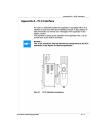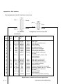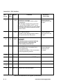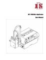
1
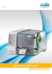
ULT-PA3000XT Applicator
User Manual
Industrial Labeling Systems,
Corporation
10 Kidder Road
Chelmsford, MA 01824 USA
Tel: +1-978-250-4414
Fax: +1-978-250-1633
www.ils-barcode.com
e-mail : [email protected]
All specifications about delivery, design, performance and weight are given to the best of our current
knowledge and are subject to change without prior notice.
2
3
Table of Contents
Table of Contents
Copyright ........................................................................................................................ 2
Table of contents ............................................................................................................ 4
1. Product Description ................................................................................. 6
Function ................................................................................................................. 6
Important Features ................................................................................................ 7
Technical Data ....................................................................................................... 7
Tamp Pads ............................................................................................................. 8
Blow Pads .............................................................................................................. 9
Roll-on Pads .......................................................................................................... 9
2. Delivery Contents .................................................................................. 10
3. General Safety Instructions .................................................................. 11
4. Applicator Component Location .......................................................... 12
5.
Mounting............................................................................................ 14
Mounting the Applicator on the Printer ..................................................................
Piercing the Universal Tamp Pad ..........................................................................
Preparing the Applicator for Using a Tamp Pad Type A1312 ...........................................
Mounting the Pad .....................................................................................................
Mounting the Stopper for the Operation Mode "Blow On" ................................................
14
15
16
17
18
6.
Connections ..................................................................................... 19
7.
Printer Configuration .......................................................................... 20
Standard Method for Changing the Printer Configuration ................................................ 20
Quick Mode for Adjusting the Delay Times ........................................................... 21
Configuration Parameter for the Applicator ........................................................... 22
8.
Adjustments ..................................................................................... 26
8.1.Mechanical Adjustments ....................................................................................
Adjusting the Pad in the Print Direction .................................................................
Adjusting the Level and the Sides of the Cylinder Unit .....................................................
Aligning the Pad to the Dispense Edge .................................................................
Opening the Holes on the Blow Tube ....................................................................
Tuning the Blow Tube ...........................................................................................
Adjusting the Stopper for the Operation Mode "Blow On" ..............................................
8.2.Pneumatic Adjustments ....................................................................................
Control Valves .............................................................................................................
Pressure Reducing Valves ..........................................................................................
Throttle Valves at the Cylinder ..............................................................................
Throttle Valves at the Manifold ..............................................................................
4
26
26
27
28
28
29
30
32
32
34
35
36
9. Operation .............................................................................................37
Loading Labels and Transfer Ribbon .................................................................. 37
Notice about Programming .................................................................................. 37
Test Mode Using the Pre-dispense Key without Print Job .................................... 38
Test Mode Using the Pre-dispense Key with Print Job ......................................... 39
Adjusting the Peel Position .................................................................................. 40
Standard Operation ............................................................................................. 41
Appendix A - PLC Interface
Appendix B - Error Messages
Appendix C - Function of the LED of the Electronics
Index
5
1. Product Description
ULT-PA3000
1. Product Description
Function
The Tamp Applicator is an optional device to use with the P, A3/300P,
A4/300P and A4/600P printers for automatically applying the printed label
onto the product.
The labels are transferred with a pad, which moves between the two positions,
starting position and labeling position, by a compressed-air driven
pneumatic cylinder.
In the starting position, the label is picked up from the printer by the pad. A sensor
at the cylinder signals when the pad is in the starting position. The label is
removed from the carrier ribbon directly at the dispense plate of the printer. It is
sucked on the pad by a vacuum via drillings at the bottom of the pad. For support,
the label is also blown against the pad with an air current coming from a blow tube.
The correct transfer of the label is controlled by a vacuum sensor. Next,
the pad is moved down into the labeling position, which is confirmed by another
sensor (labeling position sensor). Here, the label is transferred onto the
product.
The label can be applied with three different methods :
1. Tamp on
The label remains in a fixed position. The label is pressed directly onto the
product.
2. Blow on
The pad moves to a pre-adjusted position approximately 10mm away
from the product. The labels is blown onto the product by an air jet stream.
The print and apply cycle performs in a fixed position or in linear
movement of the product.
3. Roll on
The label is dispensed and moved until touching the roller of the roll on pad. At
the labeling position the roller is pressed onto the product. Then the label is
applied and rolled on by the movement of the product.
While the pad is moving back into the starting position, the vacuum
sensor checks whether the label has been removed from the pad.
6
Industrial Labeling Systems
1. Product Description
Important Features
The supporting air and the vacuum as well as the speed of the cylinder are
adjustable. That way the applicator can be adapted to different label
materials and sizes.
The operating pressure for the cylinder is reduced in comparison to the main
pressure of the applicator. So the risk of injury is reduced as far as possible.
To avoid contamination within the vacuum channels these are cleaned by air
pressure impulse at the end of each application.
For operation in a networked system the 15-pin or 25-pin applicator's PLC
(programmable logic control) interface with potential free inputs and
outputs can be used.
Technical Data
Tamp on
Blow on
Roll on
Label width in mm
25 - 116
25 - 100
25 - 116
Label height in mm
25 - 150
25 - 100
80 - 150
Cylinder stroke in mm
220/300
Stroke of tamp
below printer in mm
Compressed air press.
70/150
5 bar
Product surface
flat
Table 1 Technical Data
Industrial Labeling Systems
7
1. Product Description
8
Industrial Labeling Systems
1. Product Description
Industrial Labeling Systems
9
2. Delivery Contents
10
Industrial Labeling Systems
3. General Safety Instructions
3. General Safety Instructions
CAUTION !
Make sure that the printer is disconnected from the power supply and the
shutoff valve at the applicator is closed, while installing the delivered
components.
CAUTION !
In operation, moving parts are easily accessible.
This applies especially for the sector, where the pad is moved between the
starting and the labeling position.
During operation do not reach into that sector and keep long hair, loose
clothes, and jewellery distant. Before any manipulations in those
areas, close the shutoff valve.
CAUTION !
Do not try to manipulate or repair parts that are not described in the manuals
of the tamp applicator or the printer.
Industrial Labeling Systems
11
4. Applicator Component Location
12
Industrial Labeling Systems
4. Applicator Component Location
Industrial Labeling Systems
13
5. Mounting
14
Industrial Labeling Systems
5. Mounting
Piercing the Universal Tamp Pad
On the bottom of the pads there are holes for sucking and holding the labels by
vacuum. When an universal tamp pad is delivered these holes are covered by a foil
and must be opened according to the label size. For that purpose a piercing pin is
included in the delivery contents.
Fig. 5b Piercing the sliding foil (holes to be opened are bold)
1. Place a label (1) to be operated on the bottom side of the pad (2). The
label must be aligned to the side edge and stand over the rear edge of the pad
by 2 mm.
2. Open all the holes, which are certainly covered by the label. Open the
holes completely by turning the piercing pin (3) inside the holes.
CAUTION !
Do not open holes, which are located less than 1mm from a label edge.
Industrial Labeling Systems
15
5. Mounting
16
Industrial Labeling Systems
5. Mounting
Industrial Labeling Systems
17
5. Mounting
18
Industrial Labeling Systems
6. Connections
6. Connections
1. Prepare the connections to the power supply and to the computer as
described in the manual of the printer.
2. To contact the PLC interface use the 15-pin or 25-pin connector (for
more details see appendix A).
3. Make sure that the shutoff valve (3) is closed (lever at the valve is
turned across the air flow direction).
4. Connect the applicator to the compressed air supply.
The connector (2) for the compressed air supply is located at the
service unit. The connector is suitable for a 1/4" coupling plug (1).
5. The air pressure for operating the applicator is pre-adjusted to 5 bar.
Check the pressure at the manometer of the service unit. Correct
the adjustment if necessary : - Pull knurled knob (4) up.
- Turn knob to tune required operating pressure of 5 bar.
By turning knob clockwise the pressure rises. Push knob down.
6. Open the shutoff valve. (3/ lever is turned in the air flow direction) 7.
Switch on the power supply of the printer.
CAUTION !
The pad will immediately be moved in the starting position !
Industrial Labeling Systems
19
7. Printer Configuration
7. Printer Configuration
The tamp applicator, with its standard components, can be operated in different
ways. While the original process stays the same, the operation mode can be
chosen within the printer configuration. The most important setting is the
selection between the operation modes "Stamp on", "Blow on" and "Roll on".
Additionally the applicator has different application modes concerning the
order of printing and applying within one labeling cycle.
Print / Apply
Apply / Print
Waiting position up
Stamp on
Blow on
Roll on
x
x
x
x
x
x
Apply / Print
Waiting position down
x
Table 7a Operation and application modes
Further all operating modes can be adjusted by setting different time
delays.
Standard Method for Changing the Printer Configuration
NOTICE !
Please note the detailed information about the printer
configuration in der Operator's Manual of the printer !
1. Switch to the Offline Menu by pressing the _____ key.
3. The parameters are arranged in a tree like structure. Pressing the
key as well as the
key will scroll between the secondary
menus. By pressing the key, the selected secondary menu will be
chosen.
20
Industrial Labeling Systems
7. Printer Configuration
4. The parameters for the applicator configuration can be found under "Setup" ->
"Machine parameters" -> "Applicator".
5. Make the parameter setting as necessary.
6. Press the key several times if necessary to return to the "Online"
mode.
Quick Mode for Adjusting the Delay Times
Beside the standard method for the printer configuration there is a quick
mode to adjust the delay times available.
NOTICE !
The quick mode settings can be made during operation . The
changings affect directly the current print job.
1. Switch to the quick mode by pressing the ______ key and keep it
pressed down for at least 2 seconds.
2. The first delay time appears on the display. Adjust the delay time by
pressing the
key or the
key.
3. To switch between the different delay times press the key.
4. Press the _____ key to leave the quick setup mode. The selected
delay times are stored in the printer.
Industrial Labeling Systems
21
7. Printer Configuration
Configuration Parameter for the Applicator
Setup
Machine param.
Parameter
Meaning
Selection
Applicator
Mode of oper.
Setting the operation mode
Default : Stamp on
Mode of appl.
Setting the application mode
Default : Print-Apply
Waiting position of the pad with
dispensed label
for Blow on + Apply-Print only
Default : up
Setting the blow time
Parameter only appears in the
operation mode Blow on
Default : 0 ms
Setting the roll-on time
Parameter only appears in the
operation mode Roll on
Default : 0 ms
Setting the switch-on delay for the
supporting air
Default : 0 ms
Setting the switch-off delay for the
supporting air
Default : 270 ms
Setting the start delay
Default : 0 ms
Waiting position
Blow time
Roll-on time
Support delay on
Support del. off
Delay time
Lock time
Setting the locking time
Default : 0 ms
Peel position
Shift the position of the dispensed
label relative to the dispense plate
Default : 0,0 mm
Setting of the vacuum control
Default : EIN
Vacuum control
Stamp on
Blow on
Roll on
Print-Apply
Appy-Print
up
down
0 ... 2500 ms
in steps
of 10 ms
0 ... 5000 ms
in steps
of 10 ms
0 ... 2500 ms
in steps
of 10 ms
0 ... 2500 ms
in steps
of 10 ms
0 ... 2500 ms
in steps
of 10 ms
0 ... 2500 ms
in steps
of 10 ms
+9,9 ... -9,9 mm
in steps
of 0,1 mm
On
Off
Table 7b Applicator parameters
22
Industrial Labeling Systems
7. Printer Configuration
Mode of operation
With that parameter the methods for applying the labels on to the
product (Tamp, Blow, Roll on) can be selected.
Mode of application
The tamp applicator can be operated in two different ways referring the order of
printing and labeling within one labeling cycle.
"Print/Apply"
The print of a label is released by an external start signal (via PLC interface). At the
same moment the vacuum on the pad as well as the supporting air from the blow
tube are switched on. When the label is printed and picked up from the carrier
ribbon, the supporting air is switched off. Then the lift cylinder is driven to move the
pad down towards the labeling position. A sensor signals when the labeling
position is reached.
Following, the vacuum is switched off and the label is placed onto the product.
After that, the lift cylinder is driven to move the pad back into the starting
position. Thus, the labeling cycle is finished.
"Apply/Print"
Before starting the cyclic operation the printing and picking up of the first
label has to be released separately by a special signal via PLC interface.
Thus at the start of the cyclic operation when sending the start signal via
PLC, the first label is already on the pad. The following process is similar to the
mode "Print/Apply", but at the end of the cycle the next label is printed and
picked up by the pad. Thus, the labeling cycle is finished.
Industrial Labeling Systems
23
7. Printer Configuration
Waiting position
NOTICE !
That parameter is available only when the operation mode "Blow on" and
the application mode ''Apply/Print'' are selected.
Waiting position up
At the cyclic operation the pad with the printed label waits in the starting
position near the dispense plate of the printer for the start signal.
Waiting position down
At the cyclic operation the pad with the printed label waits in the labeling
position for the start signal. So the cycle starts directly with blowing the
label on to the product.
Blow time
Roll-on time
That parameter is available when the operation mode "Blow on" is selected.
The time period can be adjusted, when the blowing air for the transfer of the
label onto the product is switched on.
That parameter is available when the operation mode "Roll on" is selected.
The time period can be adjusted, when the roll-on pad remains in the
labeling position.
Support delay on
The supporting air from the blow tube is not immediately switched on
when the print of the label is released but delayed. The air is switched on, when the
label has covered a distance. This delay helps to prevent a turning or swinging
at the front of the label and, consequently, avoids faults when the label is being
picked up from the printer.
Support delay off
Delayed to the process of the label being picked up, the supporting air is switched
off.
In many cases, after being picked up by the pad the label edge may still stick on the
carrier ribbon. This may affect the accuracy of the label positioning or even cause
faults in the labeling. Therefore, switching off the air blow delayed can be useful to
separate the label from the carrier ribbon and neatly place the label on the surface
of the pad.
24
Industrial Labeling Systems
7. Printer Configuration
Delay time
The parameter determines the time period between the start signal and
the start of the labeling process. This delay makes it possible to release
the start of the process controlled by a sensor, for instance, when a sensor
is located within an assembly line in front of the labeling place.
Lock time
All start signals coming in following the first start signal are ignored
when they arrive within the lock time.
Peel position This parameter allows the adjustment of the presentation position of the
printed label on the dispense plate. Peel position with the initial offset value
of “0“ causes the printed label to be peeled off from the liner leaving approximately
a .1“ (2mm) wide strip of the label still adhering to the liner. The amount of label
left adhering to the liner can be altered with this parameter.
Positive offset values cause more of the label surface to protrude past the
dispense plate.
In the software an extra peel offset value is available. The offset values
from “Peel position“ and from software are added together for execution. The
software value does not replace the “Peel position“ value, but temporarily
adjusts it for the current job.
NOTICE !
The parameter of the printer configuration should be used for the basic
adjustment to optimize the labeling operation in the test
mode using the _____ key and the pre-dispense key (see chapter
"Test mode"). Adjustments for the several print jobs should be done with
the software parameter.
Vacuum control
The label transfer from the printer to the applicator is checked by a vacuum
sensor. If the transfer failes, the sucking holes on the pad will not be
covered by the label. Therefore no vacuum can originate on the pad. Following the
error message "Vacuum plate empty" will be shown and the label strip will be
fed back. If the parameter "Vacuum control" is disabled, the error
treatment described above will not be carried out. This can be helpful especially
during adjustments, because the immediate backfeed will be cancelled.
That way it is more easy to check the reasons for the faulty transfer.
For standard operation enable the vacuum control.
Industrial Labeling Systems
25
8. Adjustments
8. Adjustments
8.1. Mechanical Adjustments
The mechanical adjustments should be made in two steps.
To avoid possible collisions of the pad with other parts of the printerapplicator
system, please roughly align the pad in all directions before connecting the
applicator to the compressed air supply. The sensitive adjustment to
optimize the labeling process must be made with the compressed air
switched on.
Fig. 8.1a Adjusting the pad in the print direction
The pad (3) can be shifted in the print direction to adjust the distance between
pad and the dispense edge (4) of the printer.
1. Loosen the screw (1).
2. Shift the cylinder unit including the pad (3) inside the elongated hole
(2).
The distance between the pad and the dispense edge should be about
2mm.
3. Tighten the screw (1).
26
Industrial Labeling Systems
8. Adjustments
Industrial Labeling Systems
27
8. Adjustments
Aligning the Pad to the Dispense Edge
1
2
Fig. 8.1d Aligning the pad to the dispense edge 1.
Loosen the screw (1).
2. Adjust the parallelism between the rear edge of the pad (2) and the
dispense edge (3) by turning the pad.
3. Tighten the screw.
1
23
Fig. 8.1e Opening the holes on
the blow tube
The blow tube (1) for the
supporting air is designed for labels with a width of 120 mm. In regular distances of
15 mm the blow tube has six holes for the supporting air.
When the applicator is delivered only the two inner holes are open. The other
four holes are closed by plastic rings (2).
To adjust the supporting air to the label width, the plastic rings can be
removed from the holes.
Open all holes (3), which affect certainly the area of the label.
28
Industrial Labeling Systems
8. Adjustments
Industrial Labeling Systems
29
8. Adjustments
30
Industrial Labeling Systems
8. Adjustments
1. Place a product sample (7) at the labeling point.
2. Loosen the screws (3) enough so that you can move the stopper (2)
along the guide bars.
3. Pull the tubes (1,4) out of the push-in-fittings
4. Move the pad manually in the required labeling position.
NOTICE !
The distance between the blow pad (6) in the labeling position and the
product surface (7) must not exceed 10 mm.
5. Move the stopper (2) against the guide block (5) and tighten the
screw (3).
6. Insert the tubes (1,4) into the appropriate push-in-fittings on the
cylinder.
7. Open the shutoff valve and switch on the printer.
Industrial Labeling Systems
31
8. Adjustments
8.2. Pneumatic Adjustment
Control Valves
Fig. 8.2a Control valves
For adjusting the applicator, some functions can be released directly by
operating the control valves (3, 4, 5). To reach the control valves, loosen
two screws (1) on the front and remove the cover (2).
That way, three electric switchable control valves for compressed air
become accessible. For manual tuning, the valves can also be operated by
integrated keys.
Valve (3) to control the lift cylinder
When the printer is turned on, the pad is kept in the starting position. Switching the
valve will move down the pad into the labeling position. Normally the backswitching of the valve is controlled by the signal of the labeling position sensor.
NOTICE !
A manual release of the valve by pressing the integrated keys is only
possible with the printer switched off !
When the key 6 is pressed, the pad moves down as far as possible and
stays in that position. When operated manually, there is no controlling by the
labeling position sensor. When the key 7 is pressed, the pad moves up.
32
Industrial Labeling Systems
8. Adjustments
Double valve (4) to control the blow air
This valve controls the blow air on the pad.
In the operation mode "Blow on" the label will be blown on to the
product by switching on the valve. In the operation modes "Stamp
on" and "Roll on" the blow air is switched on for a short time after each
application to avoid contaminations within the vacuum channels.
For all functions described above, both internal valves are switched on.
By pressing the keys 8 or 9 the blow air is only switched on by one of
internal valves.
Double valve (5) to control vacuum and supporting air
One of the internal valves operates the vacuum nozzle and, consequently,
controls the vacuum on the pad for picking up the label. The other valve controls
the switch-on of the supporting air at the blow tube.
By pressing the key 10 the supporting air is switched on. Pressing the
key 11 activates the vacuum on the pad.
Industrial Labeling Systems
33
8. Adjustments
Pressure Reducing Valves
12
Fig. 8.2b Pressure reducing
valves
The pneumatic control of the
applicator contains two pressure reducing valves (1,2). Using those
valves the pressure for the two air chambers of the cylinder can be limited in
comparison to the main pressure.
The setting of the valve 1 adjusts the pressure for the upper chamber
and affects mainly the downward movement of the pad. Valve 2 limits the
pressure for the lower chamber and the speed for the upward pad movement.
NOTICE !
When the applicator is delivered, the pressure reducing valves are
adjusted to 2.5 bar and sealed. That way the pad speeds are limited and
the risk of injury is minmized.
On the other hand this setting guarantees a certain operation also when
heavy pads are used.
For that reason do not change the settings of the pressure reducing
valves !
34
cab - Produkttechnik GmbH & Co KG
8. Adjustments
The speed of the pad movement can be regulated via two throttle valves (1, 3)
on the cylinder. Those valves regulate the output speed of the
compressed air from the concerning cylinder chambers.
The valves are adjustable by turning the throttle screws (2, 4). Turning
clockwise will close the valves.
Opening the bottom valve (3) speeds up the pad moving down,
opening the top valve (1) accelerates the upward movement.
NOTICE !
The application pressure of the pad is mainly dependendon the downward
speed of the pad.
In order to reduce the application pressure turn clockwise the screw
(4). That way the downward speed of the pad will be reduced. But
the speed reduction is limited. The time for the downward movement of
the pad may not exceed 2 seconds.
Industrial Labeling Systems
35
8. Adjustments
36
Industrial Labeling Systems
9.
Industrial Labeling Systems
37
Operation
9. Operation
Test Mode Using the Pre-dispense Key without Print Job
The whole labeling process can be simulated without the need of a print job or a
connection to a computer by alternately pressing the
key and the pre-dispense key (1).
NOTICE !
Please use that test mode to adjust the parameter "Peel position" in
the printer configuration !
If the printer has no print job, pessing the
key will release the feed of a
blank label. At the same moment the vacuum at the pad as well as the supporting
air (blow tube) are switched on. After the label has been picked up by the pad, the
supporting air is switched off.
Pressing the pre-dispense key (1) will drive the lift cylinder to move the
pad down into the labeling position. A sensor signals when the labeling
position is reached.
Following, the vacuum is switched off and the label is placed onto the product.
Then, the lift cylinder is driven to move the pad back into the starting position.
Fig. 9b Pre-dispense key
38
Industrial Labeling Systems
9. Operation
Test Mode Using the Pre-dispense Key with Print Job
By pressing the pre-dispense key (1), half cycles of the labeling process
can alternately be released, provided that there is a print job.
1(st) half cycle
Pressing the key will release the print of one label. At the same moment the
vacuum at the pad as well as the supporting air (blow tube) are switched on. After
the label has been printed and picked up by the pad, the supporting air is
switched off.
2(nd) half cycle
Pressing the key will drive the lift cylinder to move the pad down into the labeling
position. The sensor signals when the labeling position is reached.
Following, the vacuum is switched off and the label is placed onto the product.
Then, the lift cylinder is driven to move the pad back into the starting position.
NOTICE !
If the label is removed from the pad manually after the first half cycle of the
labeling process, the print process will be repeated when the predispense key is pressed again.
Industrial Labeling Systems
39
9. Operation
Adjusting the Peel Position
To optimize the taking-over of the labels by the pad there are two different
parameters available for adjusting the peel position.
CAUTION !
A two-step method to adjust the peel position is described below. It is very
important to follow that procedure for a certain start after label loading and
for the re-start after error treatment !
1. Peel position in the printer configuration
First the parameter "Peel position" in the printer configuration must be adjusted (see
chapter "Printer Configuration"). That parameter should be used to compensate
tolerances between different printers. The setting of the parameter will be
stored on the printer. Adjust the printer parameter "Peel position" in such
a way, that the blank labels are totally peeled-off from the liner. For the
adjustment use the test mode without print job and simulate the
application process with the key and the pre-dispense key.
2. Peel position in the software
A second peel-off parameter is available in the software. The software value
does not replace the “Peel position“ value of the printer configuration, but
temporarily adjusts it for the current job. The offset values from “Peel
position“ and from software are added together for execution.
NOTICE !
Please make sure, that the basic adjustment described above was
made before adjusting the software peel-off parameter.
Adjust the software parameter with a real print job in such a way, that the
printed labels are totally peeled-off from the liner. It is recommended to
operate the applicator in the test mode with the pre-dispense key.
40
Industrial Labeling Systems
9. Operation
Standard Operation
1. Check all external connections before starting.
2. Load the material corresponding to the instructions in the chapter
"Loading labels and transfer ribbon". Make sure that the locking system is
locked.
3. Open the shutoff valve. 4.
Switch on the printer.
NOTICE !
Make sure that the pad is not covered by a label when switching on the
printer-applicator system.
5. Before starting the first print job, press the ______ key on the printer.
This generates a synchronous running. Remove the processed labels
manually. After a few seconds the printer carries out a brief reverse feed and
the edge of the next label is positioned at the print line.
This synchronizing also has to be carried out when the print job has been
interrupted with the_______________ key.
NOTICE !
Synchronizing is not necessary when the printhead was not lifted
between print jobs. This also applies if the printer was powered off
between print jobs.
6. Start a print job.
7. Start the labeling process via PLC interface.
If an error occurs while the applicator is operating, this is shown in the display of
the printer (for types of errors and how to treat them see appendix B).
Industrial Labeling Systems
41
9. Operation
42
Appendix A - PLC Interface
Industrial Labeling Systems
A-1
Appendix A - PLC Interface
Pin Assignment of the PLC Interface Connectors
Pin 1
Pin 14
Pin 1
Pin 9
Pin 8
Pin 25
Pin 13
Fig. A-2 Pin
Pin 15
Assignment of the PLC Interface
Connectors
Pin
25 pin
1
2
3
4
5
6
7
8
9
10
11
12
13
14
15
16
17
18
19
20
21
22
23
24
25
Pin
15 pin
1
2
3
4
5
6
7
8
9
10
11
12
13
14
15
Signal
Signal
old *
Direction
E0.1 (+)
E0.2 (+)
E0.3 (+)
A0.1
A0.2
A0.3
A0.4
GND
A0.5
XSTRT
XSTP
XDREE
XDNB
XEDG
XSAA
XSOE
GND
XEDST
Input
Input
Input
Output
Output
Output
Output
Output
Output
E0.5 (-)
XRSR
Input
E0.1 (-) XSTRTR
E0.2 (-)
XSTPR
E0.3 (-) XDREER
A0.7
XSUE
A0.8
XETF
COM
RÜL
24V (Out)
24P
A0.9
XESP
E0.5 (+)
A0.10
Input
Input
Input
Output
Output
Output
Output
Output
XRS
Input
/XSOE
Output
Function
Start signal
Stop signal (external error)
Print first label
Printer not ready
No existing print job
General error message
Pad in starting position
Ground (0V) of the printer
Special signal X command
not used
External RESET (reverse line)
do not connect
do not connect
Start signal (reverse line)
Stop signal (reverse line)
Print first label (reverse line)
Pad in labeling position
Applicator fault
Common potential (for all outputs)
Operating voltage +24V, Si T 100mA
Special signal X command
not used
External RESET
do not connect
Pad in starting position (inverted)
Tabelle A-1 Pin Assignment of the PLC Interface Connectors *
Signal names at Apollo and Hermes applicators
A-2
Industrial Labeling Systems
Appendix A - PLC Interface
Comments on the Signals
NOTICE !
The numbers in the brackets concern to the 15 pin connector !
Pin
Pin
25 pin 15 pin
.
Signal
Comment
Activation /
active state
1
1
E0.1 (+) Start signal
To start the cyclic labeling process.
Switch on +24V
between pin1 and
pin14 (9)
2
2
E0.2 (+) Stop signal (external error)
The following functions are released
- to finish the print of a label and its
picking-up by the pad
- to interrupt or to stop the beginning of the
labeling process
- to make the pad moving back into the
starting position
- to disregard of all following start signals
- if activated during the labeling phase, the
display will show the message 'Host stop/
error'. (no message during print process)
Switch on +24V
between pin2 and
pin15 (10)
3
3
E0.3 (+) Print first label
for application mode "Apply/Print" only :
to release the print of the first label and
its picking-up by the pad
Switch on +24V
between pin3 and
pin16 (11)
4
4
A0.1
Printer not ready
Error message of the printer.
The error type is shown on the display.
After error correction, the print of the last
label will be repeated.
Contact between
pin4 and pin19 (14)
is open.
5
5
A0.2
No existing print job. State message.
There is no print job currently available.
Contact between
pin5 and pin19 (14)
is open.
Table A-2 Comments on the signals
Industrial Labeling Systems
A-3
Appendix A - PLC Interface
Pin
25 pin
Pin
15 pin
Signal
Comment
Activation /
active state
6
6
A0.3
General error message
General error message of both, printer
and applicator.
This message is shown when one of the
two errors either XDNB or XETF occurs.
Important in case that only one error signal
of the applicator can be analysed from the
system control.
Contact between
pin6 and pin19 (14)
is open.
7
7
A0.4
Pad in starting position
The pad is in the starting position where it
picks up the label from the printer.
Contact between
pin7 and pin19 (14)
is open.
8
8
GND
9
A0.5
Ground (0V)
CAUTION !
Pin 8 must not be connected with the
ground of the PLC. Otherwise the
dc decoupling would be lost.
Special signal x command (bit 0)
is controlled by the X command in the
direct programming
for detailed description of the X command
see the programming manual
if bit 0 is set :
Contact between
pin9 and pin19
is closed.
10
11
E0.5 (-) Reverse line of the external RESET signal
12
13
14
9
E0.1 (-) Reverse line of the start signal
Table A-2 Comments on the signals (continuation)
A-4
Industrial Labeling Systems
Appendix A - PLC Interface
Pin
25 pin
Pin
15 pin
Signal
Comment
Activation /
active state
15
10
E0.2 (-) Reverse line of the stop signal
16
11
E0.3 (-) Reverse line of the signal "Print first label"
17
12
A0.7
Pad in labeling position
The pad is in the position where the label
is applied to the product
Contact between
pin17(12) and
pin19 (14)
is open.
18
13
A0.8
Applicator fault
Signal is active after one of the following
errors occured :
- pad has not reached the labeling position
within 2s after the start of the downward
movement
- pad has not reached the starting position
within 2s after the start of the upward
movement
- a printed label has not been picked up by
the pad properly or it fell down during the
movement of the pad (message of the
vacuum sensor)
- the label is still on the pad when the
pad moves back up (message of the
vacuum sensor)
The type of fault is shown in the display
of the printer.
After fault correction, the print of the last
label printed before the fault occured
will not be repeated.
Contact between
pin18(13) and
pin19 (14)
is open.
19
14
COM
Line with common potential for all output
signals
(may be connected with 24V or GND)
Table A-2 Comments on the signals (continuation)
Industrial Labeling Systems
A-5
Appendix A - PLC Interface
Pin Pin
25 pin 15 pin
20
21
15
Signal
Comment
Activation /
active state
24V(Out) Operating voltage +24V, Si T 100mA
The applicator system provides an
operation voltage of 24 V
CAUTION !
You must not apply any external
voltage on pin 20(15) !
The operating voltage allows the use of
the applicator without being part of a
networked system.
Example : To generate the start signal by
a foot switch.
A0.9
Special signal x command (bit 3)
is controlled by the X command in the
direct programming
for detailed description of the X command
see the programming manual
if bit 3 is set :
Contact between
pin21 and pin19
is closed.
22
23
E0.5 (+) External RESET
to reset printer and applicator
Switch on +24V
between pin23 and
pin11
24
25
A0.10 Pad in starting position (inverted)
The pad is in the starting position where it
picks up the label from the printer.
Contact between
pin25 and pin19
is closed.
Table A-2 Comments on the signals (continuation)
A-6
Industrial Labeling Systems
Appendix A - PLC Interface
Circuit Diagrams of Inputs and Outputs
The inputs are optocouplers with a current limiting resistor of 2.4k~ in
the input circuit for an operating voltage of 24V.
For each signal [IN (+)] there is a separate reverse line [IN (-)] at the plug
connector. From that, the following matching pairs of signals result :
Pin14/(9) - E0.1 (-)
Pin2 - E0.2 (+)
Pin15/(10) - E0.2 (-)
Pin3 - E0.3 (+)
Pin16/(11) - E0.3 (-)
Pin23 - E0.5 (+)
Pin11 - E0.5 (-)
Fig. A-3 Circuit of the inputs
A-7
Appendix A - PLC Interface
A-8
Industrial Labeling Systems
Appendix A - PLC Interface
A-9
Appendix A - PLC Interface
A - 10
Industrial Labeling Systems
Appendix A - PLC Interface
Industrial Labeling Systems
A - 11
Appendix A - PLC Interface
A - 12
Appendix B - Error Messages
Appendix B - Error Messages
Error Messages of the Printer
Detailed information about printer errors (e.g. 'Paper out', 'Ribbon out',
etc.), their causes and correction methods can be found in the Operator's manual
for the printer (Appendix C).
NOTICE !
With the installation of an applicator the error treatment expands. This
means in particular, that after correcting the error and before the
correction is quit with the_________ key, an additional label feed
has to be released using the_____ key.
This synchronizes the process of printing and labeling. Possibly dispensed
blank labels have to be removed manually.
After quitting the error message the label caused the error will be printed
once more.
Error Messages of the Applicator
The following table gives an overview of error messages and their possible
causes. It also suggests methods to resolve the problem. After error
correction, always quit the error message of the applicator
with the _____ key.
To reprint the label where the applicator error occurred, a new print job has to be
released.
Resuming the Operation in the Application Mode "Apply/Print"
In the application mode "Apply/Print" a printed label must be picked by the pad
before starting the cyclic operation. Therefore after an error first the signal "Print
first label" must be sent or the pre-dispense key must be pressed before the
cyclic operation can be started.
B-1
Appendix B - Error Messages
A 1000
Error Message
Possible cause
Fehlerbehandlung
Air pressure ins.
Compressed air is switched off.
Check the shutoff valve
Host stop/ error
Labeling process has been
Interrupted by an stop signal via
PLC interface
Label the product manually if
necessary
Label not depos.
Label has not been placed onto
the product; after the pad has
moved back the label still sticks
on the pad
Label the product manually
Lower position
Pad has not reached the labeling
position within 2s after the
movement of the pad
Check the pneumatic
adjustments (esp. the lower
throttle valve of the cylinder);
Check the applicator for
heaviness of its mechanics;
Check the labeling position
sensor (service);
Label the product manually
Refl. sensor blk.
There has been no change of the
switch state at the upper control
sensor (at the cylinder) between
the start of the labeling process
and the signal from the labeling
position sensor
Check the sensor (service)
Upper position
Pad has not reached the starting
position within 2s after the pad
has moved back; or pad has left
starting position unauthorized
Check the pneumatic
adjustments (esp. the upper
the throttle valve of the
cylinder);
Label the product manually
Vac. plate empty
Label has not been picked up
properly by the pad; or label fell off
the pad before it could be placed
onto the product
If possible, place the 'lost' label
onto the product manually;
Otherwise stop print job and
start again with adapted
parameters (e.g. count)
Table B-1 Error Messages of the Applicator
B-2
Industrial Labeling Systems
Appendix C - Function of the LEDs of the Electronics
LED No. Colour Function Active state
1
2
3
4
5
6
7
yellow
yellow
green
green
green
green
green
Label on the pad
On
Operating voltage 5 V On
PLC signal XSTRT On
PLC signal XSTP
On
PLC signal XDREE On
PLC signal XRS
On
not used
C-1
C-2
A 1000
Index
Index
H
Host stop / error A-3, B-2
A
Air pressure ins. B-2 Air
pressure 7, 19 Applicator
fault A-2, A-5 Apply/Print
20, 22ff.
K
Keys (control valves) 32f.
L
B
Blowing air tube 17
Blowing air 24, 33
Blow on 6f., 18, 20, 22ff., 33
Blow pad 6, 9 Blow time 22,
24 Blow tube 6, 12, 28f., 38f.
C
CANCEL key (printer) 41
Connections 19, 41
Connector for compressed air 13,19
Control valves 32 Cover 32, 34
Cylinder unit 12, 16, 26f.
Labeling position 6, 18, 23f., 32,
38f., A-2, A-5
Labeling position sensor 6, 23, 32,
38f.
Label not depos. B-2
Label on the pad C-1
LED C-1
Level adjustment 27
Lock time 22, 25 Lower
position 32, B-2
M
Manifold 36
Manometer 12, 19 MODE
key (printer) 20f.
D
Delay time (start) 22, 25
Delay times 21, 25
Delivery contents 10
Dispense edge 6, 26ff
N
No existing print job A-2f.
O
E
Error 41
Error messages B-1f.
Error messages applicator B-1f.
Error messages printer B-1
F
FEED key (printer) 25, 38f., B-1
G
General error message A-2, A-4
Industrial Labeling Systems
Operating pressure 7, 19
Operating voltage A-2, A-6, C-1
Operation mode 20, 22ff.
Index
P
Pad in labeling position A2, A-5
Pad in starting position A-2, A-4
PAUSE key (printer) B-1 PCB
Applicator control C-1 Peel-off
mode 37 Peel position 22, 25,
38ff. Peripheral port 14 Piercing
pin 10, 15
Pin assignment of the PLC interface
A-2ff.
PLC 41
PLC interface 7, 13, 19, A-1ff.
Pneumatic cylinder 6, 12 Predispense key 13, 25, 38f.
Pressure reducing valves 30
Print/Apply 20, 22f. Printer
configuration 20ff. Printer not
ready A-2f. Print first label A-2f.
Start signal A-2f.
Stopper 10, 18, 30
Stop signal A-2f.
Supporting air 6f., 22, 24, 28f., 33, 36,
38f.
Switch-off delay supporting air 22, 24
Switch-on delay supporting air 22, 24
Synchronizing 41
T
Tamp on 6f.
Tamp pad 6, 8 Technical
data 7 Test mode 38f.
Throttle valves 12, 35f.
U
Universal tamp pad 8, 10, 12, 15f.
Upper position 32, B-2
Q
Quick mode for adjusting delay
times 21
R
Refl. sensor blk. B-2
RESET A-2, A-6
Roll on 6f., 20, 22ff., 33
Roll-on pad 6, 9, 24 Rollon time 22, 24
V
Vacuum 6f., 15, 23, 33, 36, 38f.
Vacuum control 22, 25 Vacuum
nozzle 33 Vacuum plate empty B2 Vacuum sensor 6, 25 Vacuum
tube 17
W
Waiting position 20, 22, 24
S
Safety instructions 11
Service unit 11, 13, 19, 30
Shutoff valve 11, 13, 19, 31, 41, B-2
Side adjustement 27 Signals (PLC) A1ff., C-1 Special signal A-2, A-4, A-6
Speed of the pad movement 7, 35
Stamp on 20, 22f., 33 Starting
position 6, 19, 32, 38f.
Industrial Labeling Systems