1
Tamp Applicator with Lift Cylinder
Type 1300
Operating Instructions
Edition 4/03
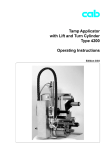
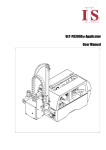
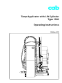
Tamp Applicator with Lift Cylinder Type 1300
cab-Produkttechnik
Gesellschaft für
Computer- und Automationsbausteine mbH & Co KG
Postfach 19 04
Wilhelm-Schickard-Straße 14
Telefon 0721 / 66 26-0
Telefax 0721 / 66 26-249
D-76007 Karlsruhe
D-76131 Karlsruhe
copyright by cab / 9008170 / xxx / x
Angaben zu Lieferumfang, Aussehen, Leistung, Maßen und Gewicht entsprechen unseren Kenntnissen zum Zeitpunkt der
Drucklegung. Änderungen sind vorbehalten.
All specifications about delivery, design, performance and weight are given to the best of our current knowledge and are
subject to change without prior notice.
2
cab - Produkttechnik GmbH & Co KG
Tamp Applicator with Lift Cylinder Type 1300
Table of Contents
Copyright ......................................................................................................................... 2
Table of Contents ............................................................................................................ 3
1. Product Description .................................................................... 4
Function .................................................................................................................. 4
Versions of the Tamp Applicator ............................................................................ 5
Positions of the Pad ............................................................................................... 6
Technical Data ........................................................................................................ 6
2. Equipment Supplied .................................................................... 7
3. Safety Instructions ...................................................................... 8
4. Installation ................................................................................... 9
Installing the Tamp Applicator ................................................................................ 9
Installation of the Service Unit ............................................................................. 11
Connections ......................................................................................................... 12
5. Adjustments ............................................................................... 13
5.1. Mechanical Adjustments ...................................................................................... 13
Angle of the Pad in the Starting Position ............................................................. 13
Adjusting the Level of the Cylinder Unit .............................................................. 14
Tuning of the Blow Tube ...................................................................................... 15
Adjustment of the Labelling Position Sensor ....................................................... 15
5.2. Pneumatic Adjustments ....................................................................................... 16
Control Valves ...................................................................................................... 16
Throttle Valves at the Cylinders ........................................................................... 18
Slide Valve at Cylinder 1 ...................................................................................... 20
Throttle Valves at the Manifold ............................................................................ 21
5.3. Selection of the Operation Mode ........................................................................ 22
Operation Mode 'Printing / Labelling' ................................................................... 22
Operation Mode 'Labelling / Printing - Waiting in the Starting Position' .............. 22
Operation Mode 'Labelling / Printing - Waiting in the Transition Position' .......... 23
Function of the Pre-dispense Key ....................................................................... 24
Setting the Operation Mode and the Delay Times .............................................. 26
Print Info Display .................................................................................................. 29
6. Operation .................................................................................. 30
Appendix A - PLC Interface
Appendix B - Error Messages
Appendix C - Function of the LED of the Applicator Electronics
Index
EC-Conformity Declaration
cab - Produkttechnik GmbH & Co KG
3
Tamp Applicator with Lift Cylinder Type 1300
1.
Product Description
Function
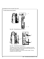
The Tamp Applicator with Lift Cylinder Type 1300 is an extra device to
use with the Hermes label printer for automatically applying the
printed label onto the product.
The labels are transferred with a pad, which moves between the
starting position and labelling position, by two compressed-air driven
pneumatic cylinder.
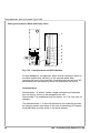
In the starting position, the label is picked up from the printer by the
vacuum plate of the pad. Cylinder 1 is situated in its upper end
position. This position is recognized by sensor 1. Cylinder 2 is swung
to the dispense edge. It is situated in its lower end position. The label
is removed from the carrier ribbon directly at the dispense edge of the
printer. It is sucked on the pad by a vacuum via drillings at the bottom
of the pad. For support, the label is also blown against the pad with an
air current coming from a blow tube. The correct transfer of the label
is controlled by a vacuum sensor.
After taking the label successfully, the pad is moved by cylinder 2 into
the transition position, which is confirmed by sensor 3. Following
cylinder 1 is pushed forwards and the pad is moved into the labelling
position. This position is signaled by sensor 3 (the labelling position
sensor). Here, the label is stamped onto the product by the pad.
Then the pad is moved back into the transition position. This position
is recognized by sensor 1. Next, the pad is swung by cylinder 2 into
the starting position.
While the pad is moving back, the vacuum sensor checks whether the
label has been removed from the pad.
Specially adapted pads can be used for different label sizes.
The control unit of the applicator is connected with the Hermes on its
SPI interface using the peripheral connector for cab-applicators at the
front side of the printer.
For operation in a networked system the applicator's PLC
(programmable logic control) interface with potential free inputs and
outputs can be used.
4
cab - Produkttechnik GmbH & Co KG
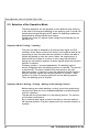
Tamp Applicator with Lift Cylinder Type 1300
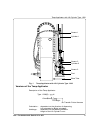
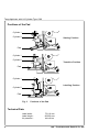
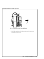
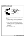
Sensor 1
Cylinder 1
Sensor 3
Cylinder 2
Sensor 2
Pad
Blow Tube
Fig. 1
Tamp Applicator with Lift Cylinder Type 1300
Versions of the Tamp Applicator
Description of the Tamp Applicator
Type 1300(R) - yyy H
Orientation
Lift Height
for Transfer Printer Hermes
Orientation : dependent on the direction of dispensing
Left orientated or Right orientated
Hublänge :
dependent on the labelling distance
Height of the Lift Cylinder in mm
cab - Produkttechnik GmbH & Co KG
5
Tamp Applicator with Lift Cylinder Type 1300
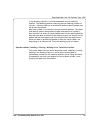
Positions of the Pad
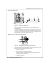
Cylinder 1
Cylinder 2
Starting Position
Pad
Cylinder 1
Cylinder 2
Transition Position
Pad
Cylinder 1
Labelling Position
Cylinder 2
Pad
Fig. 2
Positions of the Pad
Technical Data
Label width :
Label height :
Air pressure :
6
75-116 mm
80-200 mm
4 bis 6 bar
cab - Produkttechnik GmbH & Co KG
Tamp Applicator with Lift Cylinder Type 1300
2.
Equipment Supplied
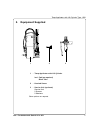
1
1
2
3
- Tamp Applicator with Lift Cylinder
incl. Pad (as required)
Blow Tube
2
- Knurled Screw
3
- Service Unit (optional)
Service Unit
2 Screws
2 Washers
Other options on request.
cab - Produkttechnik GmbH & Co KG
7
Tamp Applicator with Lift Cylinder Type 1300
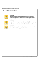
3.
Safety Instructions
CAUTION !
Make sure that the Hermes is disconnected from the power
supply and the valve at the service unit as well as the shutoff
valve at the applicator are closed, while installing the delivered
components.
CAUTION !
In operation, moving parts are easily accessible. Therefore, keep
long hair, loose clothes, and jewellery distant. Before any
manipulations in those areas, close the shutoff valve.
CAUTION !
Do not try to manipulate or repair parts that are not described in
the manuals of the tamp applicator or the Hermes.
8
cab - Produkttechnik GmbH & Co KG
Tamp Applicator with Lift Cylinder Type 1300
4.
Installation
Installing the Tamp Applicator
1
2
1
2
3
4
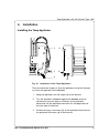
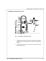
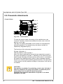
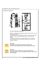
Fig. 4a
Installation of the Tamp Applicator
There are each two hinges (1, 2) at the applicator and at the Hermes
to mount the applicator at the Hermes.
1.
Hang the applicator into the hinges (2) of the Hermes.
2.
Turn the applicator sidewards against the Hermes as far as
necessary to plug the plug-in connector of the applicatorelectronics into the peripheral connector for cab-applicators at
the front side of the printer.
3.
Contact the plug-in connector (3) of the applicator-electronics at
the peripheral connector (4) of the Hermes.
cab - Produkttechnik GmbH & Co KG
9
Tamp Applicator with Lift Cylinder Type 1300
1
2
Fig. 4b Installation of the Tamp Applicator
4.
10
Attach the applicator at the Hermes by screwing the knurled
screw (2) into the hole (1).
cab - Produkttechnik GmbH & Co KG
Tamp Applicator with Lift Cylinder Type 1300
Installation of the Service Unit
1
2
3
Fig. 4c
Installation of the Service Unit
1.
Fasten the service unit (1) at the rear of the Hermes using the
washers and the screws which are contained in the equipment
supplied.
2.
Insert the tube of the service unit (2) into the push-in fitting (3).
Insert the tube firmly.
cab - Produkttechnik GmbH & Co KG
11
Tamp Applicator with Lift Cylinder Type 1300
Connections
2
2
3
4
1
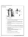
Fig. 4d Connections
1.
Prepare the connections to the power supply and to the computer
as described in the manual of the Hermes.
2.
To contact the PLC interface use the 15-pin connector at the left
side of the applicator below the shutoff valve (for further details
see appendix A).
3.
Make sure that the shutoff valve (1) is closed (lever at the valve is
turned vertical).
4.
The connector (3) for the compressed air supply is located at the
service unit. The connector is suitable for a 1/4" coupling plug (4).
5.
The air pressure for operating the applicator has to be adjusted at
the service unit.
Pull knurled knob (2) up.
Turn knob to tune the required operating pressure (4-6 bar).
By turning knob clockwise the pressure rises.
Push knob down.
-
12
6.
Switch on the power supply of the Hermes.
7.
Open the shutoff valve (1/lever is turned horizontal).
cab - Produkttechnik GmbH & Co KG
Tamp Applicator with Lift Cylinder Type 1300
5.
Adjustments
All label applicators have passed a previous run at the factory.
It may be useful to do some more fine tuning when the applicator is
installed. This refers mainly to those parameters, which are significant
as part of a networked system as well as pneumatic settings, which
have an influence on the application rate.
5.1. Mechanical Adjustments
Angle of the Pad in the Starting Position
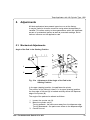
1
2
3
4
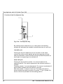
Fig. 5.1a Adjustment of the Angle of the Pad in the
Starting Position
In its upper (starting) position, the pad faces the printer.
The position of the pad unit is best, if in its upper (starting) position
the rear edge of the pad (3) is located vertically above the dispense
edge of the printer (4).
The angle of the pad can be altered as follows :
1.
2.
3.
Loosen the counter nut (2).
Move the cylinder rod (1).
Turning upwards - the pad moves away from the dispense edge.
Turning downwards - the pad moves closer to the dispense edge.
Counter the nut.
cab - Produkttechnik GmbH & Co KG
13
Tamp Applicator with Lift Cylinder Type 1300
Adjusting the Level of the Cylinder Unit
2
1
2
4
3
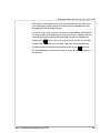
Fig. 5.1b Adjusting the Level
There are two screws (2) at the rear side of the carrier plate (1) of the
applicator.
14
1.
Loosen the knurled screw at the front side of the applicator and
turn the applicator away from the Hermes.
Now the two screws (2) at the rear side of the carrier plate are
accessible.
2.
For level adjustment, loosen the two screws (2) and move the
whole unit.
In the upper (starting) position the pad should be located slightly
above the dispense edge of the Hermes. The distance between
the pad and the dispense edge of the Hermes is recommended to
be around 1 mm.
3.
After adjusting tighten the screws.
cab - Produkttechnik GmbH & Co KG
Tamp Applicator with Lift Cylinder Type 1300
Tuning of the Blow Tube
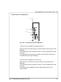
1
Fig. 5.1c
2
3
Tuning the Blow Tube
The blow tube (2) for the supporting air can be rotated around its
longitudinal axis.
To rotate the blow tube and, consequently, change the direction of the
air current, hold slotted screw (3) with a screwdriver while loosening
counter nut (1). Adjust the tube until the air current is aligned with the
dispense edge of the printer. Tighten counter nut.
Adjustment of the Labelling Position Sensor
1
2
Fig. 5.1d
Adjusting the Labelling Position Sensor
The labelling pressure for stamping the label onto the product can be
altered by moving the labelling position sensor.
1.
Loosen the screw (1).
2.
Shift the sensor by moving the cable (2).
Shifting the sensor upwards will reduce the labelling pressure,
shifting downwards will extend it.
3.
Tighten the screw (1).
cab - Produkttechnik GmbH & Co KG
15
Tamp Applicator with Lift Cylinder Type 1300
5.2. Pneumatic Adustments
Control Valves
1
2
3
4
5
Fig. 5.2a Control Valves
To reach the control valves, the casing of the manifold has to be
removed. Therefore, loosen the screws at the cover, two on the left
and one on the right.
That way, four electric switchable control valves for compressed air
become accessible. For manual tuning, the valves can also be
operated by integrated keys (1).
The functions of the valves are as explained below.
'Zylinder' (2/cylinder 1) :
Two-way valve to control cylinder 1.
When the valve is switched off the pad is kept respectively moved in
the upper end position of cylinder 1. Switching on the valve will move
down the pad. Normally the disconnection of the valve is controlled by
the signal of the labelling position sensor. When operated manually,
there is no controlling by the labelling position sensor. The pad moves
to the bottom as far as possible and stays in that position until the key
is released.
CAUTION !
Pay attention to cylinder 2 by switching on this valve. Cylinder 2
has to be situated in its upper end position, it means the pad is
swung away from the peel-off edge of the printer.
Otherwise the movement downwards of cylinder 1 can cause
damages at the pad.
16
cab - Produkttechnik GmbH & Co KG
Tamp Applicator with Lift Cylinder Type 1300
'Stützluft' (3/supporting air) :
This valve controls the switch-on of the supporting air at the blow tube.
'Zylinder' (4/cylinder 2) :
Two-way valve to control cylinder 2.
Switching on the valve will move the pad into the upper end position of
cylinder 2. The pad is swung away from the peel-off edge of the
printer.
'Vakuum' (5/vacuum nozzle) :
This valve operates the vacuum nozzle and, consequently, controls
the vacuum on the pad for picking up the label.
cab - Produkttechnik GmbH & Co KG
17
Tamp Applicator with Lift Cylinder Type 1300
Throttle Valves at the Cylinders
1
2
Fig. 5.2b Throttle Valves at Cylinder 1
3
4
Fig. 5.2c Throttle Valves at Cylinder 2
The speed of the cylinder movement can be regulated via throttle
valves. The setting of those valves determines the speed which the
compressed air escapes the container.
The valves are adjustable by turning the throttle screws. Turning
clockwise will close the valves.
18
cab - Produkttechnik GmbH & Co KG
Tamp Applicator with Lift Cylinder Type 1300
Cylinder 1
-
Cylinder 2
-
Throttle valves 1, 2
A wider opening of valve (2) - accelerates the
downward movement of the pad
A wider opening of valve (1) - accelerates the upward
movement of the pad
Throttle valves 3, 4
A wider opening of valve (3) - accelerates the upward
movement of the pad
A wider opening of valve (4) - accelerates the
downward movement of the pad
cab - Produkttechnik GmbH & Co KG
19
Tamp Applicator with Lift Cylinder Type 1300
Slide Valve at Cylinder 1
1
Fig. 5.2d Slide Valve at Cylinder 1
Cylinder 1 is additional equipped with a slide valve (1), which can only
be actuated manually.
If the slide valve is closed (operate) cylinder 1 is kept in its upper end
position. This fact is special important when the shutoff valve is
closed.
The slide valve should only be opened (bleed), if it is necessary to
move the pad for service for example cleaning the pad, removing
fragments of labels.
CAUTION !
Pay attention to the pad while opening the slide valve.
It should be swung away from the peel-off edge of the printer.
CAUTION !
The slide valve has always to be closed during operation.
Otherwise cylinder 1 can be moved without control. This fact can
cause damages.
20
cab - Produkttechnik GmbH & Co KG
Tamp Applicator with Lift Cylinder Type 1300
Throttle Valves at the Manifold
1
2
Fig. 5.2e Throttle Valves at the Manifold
Throttle valve to regulate the supporting air (1)
With this valve the supporting air to blow the label onto the pad can be
adjusted.
Turn the throttle screw to adjust the valve. Turning clockwise will close
the valve.
The valve has to be tuned in such a way, that the label is blown onto
the pad without turning or swinging.
Throttle valve to regulate the vacuum (2)
With this valve the vacuum to suck the label onto the pad can be
adjusted.
Turn the throttle screw to adjust the valve. Turning clockwise will close
the valve.
The vacuum can be adjusted until the label totally sticks on the
vacuum plate.
cab - Produkttechnik GmbH & Co KG
21
Tamp Applicator with Lift Cylinder Type 1300
5.3. Selection of the Operation Mode
The tamp applicator can be operated in three different ways referring
to the order of printing and labelling of one applying cycle. A mode can
be selected through actuating a DIP switch. All operating modes can
be adjusted by setting different time delays.
Furthermore, there is a special mode using the pre-dispense key for
adjusting, etc.
Operation Mode 'Printing / Labelling'
The print of a label is released by an external start signal (via PLC
interface). At the same moment the vacuum on the pad as well as the
supporting air from the blow tube are switched on. When the label is
printed and picked up from the carrier ribbon, the supporting air is
switched off and cylinder 2 is driven in such a way that the pad is
swung into the transition position. A sensor signals when the transition
position is reached.
Following cylinder 1 is moved downwards. The labelling position
sensor recognizes when the labelling position is reached. The vacuum
is switched off. The label is placed onto the product by the pad.
After that cylinder 1 is driven to move the pad back into the transition
position. A sensor signals the transition position of cylinder 1. Next
cylinder 2 is driven to move the pad back into the starting position.
Thus, the labelling cycle is finished.
Operation Mode 'Labelling / Printing - Waiting in the Starting Position'
Before starting the mode 'labelling / printing' the printing and picking
up of the first label has to be released separately by a special signal
(via PLC interface).
The pad with the printed label is in the starting position. The vacuum
on the plate is switched on.
By an external start signal cylinder 2 is driven to move the pad into
the transition position. A sensor signals when the transition position is
reached.
22
cab - Produkttechnik GmbH & Co KG
Tamp Applicator with Lift Cylinder Type 1300
In the following cylinder1 is moved downwards into the labelling
position. The labelling position sensor signals the labelling position of
cylinder 1. Now the vacuum is switched off and the label is placed onto
the product by the pad.
After that cylinder 1 is moved up into the transition position. The upper
end position sensor recognizes the upper end position of cylinder 1.
Next cylinder 2 is driven to move the pad back into the starting position.
Now the next label is printed. At the same moment, the vacuum on the
pad as well as the supporting air from the blow tube are switched on.
When the label is printed and picked up from the carrier ribbon, the
supporting air is switched off. Thus, the labelling cycle is finished.
Operation Mode 'Labelling / Printing - Waiting in the Transition Position'
This mode differs from the above described mode 'Labelling / Printing Waiting in the Starting Position' in so far as the printed label is
immediately moved into the transition position and is being held there.
Consequently the next cycle begins by moving down cylinder 1 and
pressing the label onto the product.
cab - Produkttechnik GmbH & Co KG
23
Tamp Applicator with Lift Cylinder Type 1300
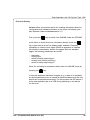
Function of the Pre-dispense Key
1
Fig. 5.3a Pre-dispense Key
By pressing the pre-dispense key (1), half cycles of the labelling
process can alternately be released, provided that there is a print job.
1(st) half cycle
Pressing the key will release the print of one label. At the same
moment the vacuum at the pad as well as the supporting air (blow
tube) are switched on. After the label has been printed and picked up
by the pad, the supporting air is switched off.
2(nd) half cycle
Pressing the key will drive cylinder 2 to move the pad into the
transition position. The sensor signals when the transition position is
reached.
Following cylinder 1 is moved downwards. The vacuum is switched off
and the label is placed onto the product by the pad.
After that cylinder 1 is driven to move up. The upper end position
sensor signals the transition position of cylinder 1. Then, cylinder 2 is
driven to move the pad back into the starting position.
24
cab - Produkttechnik GmbH & Co KG
Tamp Applicator with Lift Cylinder Type 1300
If the label is removed from the pad manually after the first half cycle
of the labelling process, the print process will be repeated when the
pre-dispense key is pressed again.
If there is no print job, only the movements of the pad as described for
the second part of the labelling cycle are carried out, pressing the key.
The first half cycle of the labelling process can also be released by
pressing the
key on the control panel of the printer. In that case,
a blank label is picked up by the pad. That way, the whole labelling
process can be simulated by alternately pressing the
key and
the pre-dispense key without the need of a print job or a connection to
a computer.
cab - Produkttechnik GmbH & Co KG
25
Tamp Applicator with Lift Cylinder Type 1300
Setting the Operation Mode and Delay Times
1
2
3
4
5
6
7
Fig. 5.3b Potentiometers and DIP-Switches
For best adaptation, the applicator offers several methods to adjust to
the whole system and, therefore, to the required needs. After
removing the cover of the manifold, 6 potentiometers as well as 4 DIP
switches become accessible by which the parameters can be set.
Potentiometers
Potentiometer 1 is sealed. Certain voltage settings are pre-adjusted
from the factory and not to be changed by the user.
Potentiometer 2 is preadjusted from the factory, too. The user may not
change it.
The potentiometers 3 - 6 offer the adjustment of the labelling process
by changing certain time delays. If any one of the settings is changed
the actual value is briefly shown in the printer display.
26
cab - Produkttechnik GmbH & Co KG
Tamp Applicator with Lift Cylinder Type 1300
Potentiometer (3) : tSA - switch-off delay supporting air 0...2,5 s
Delayed to the process of the label being picked up, the supporting air
is switched off.
In many cases, after being picked up by the pad the label edge may
still stick on the carrier ribbon. This may affect the accuracy of the
label positioning or even cause faults in the labelling. Therefore,
switching off the air blow delayed can be useful to separate the label
from the carrier ribbon and neatly place the label on the surface of the
pad.
Potentiometer (4) : sSE - switch-on delay supporting air 0...20 mm
The supporting air from the blow tube is not immediately switched on
when the print of the label is released but delayed. The air is switched
on, when the label has covered a certain distance sSE.
This delay helps to prevent a turning or swinging at the front of the
label and, consequently, avoids faults when the label is being picked
up from the printer.
The parameter measures the distance covered by the label before the
supporting air is switched on, and it is not depending on the print
speed. This way, the position of the label can be determined until the
air is switched on.
Potentiometer (5) : tSP - locking time 0...2,5 s
All start signals coming in following the first start signal are ignored
when they arrive within the locking time tSP.
Potentiometer (6) : tVS - start delay 0...2,5 s
The parameter tVS determines the time period between the start signal
and the start of the labelling process. With this delay it is possible to
release the start of the labelling process sensor controlled, for
instance, when a sensor is located on an assembly line in front of the
labelling place.
cab - Produkttechnik GmbH & Co KG
27
Tamp Applicator with Lift Cylinder Type 1300
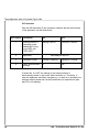
DIP-Switches
With the DIP-switches (7) the operation mode as well as the firmware
of the applicator can be determined.
DIP Switch
Parameter
ON
OFF
1
Waiting position in
operating mode
Labelling/Printing
(only DIP2 and
DIP3 OFF)
Starting Position
Transition Position
2
Applicator
3
Operation mode
Printing / Labelling
Labelling / Printing
4
Save potentiometer
settings
no
yes
has always to be OFF
If switch No. 4 is OFF the setting of the potentiometers is
automatically stored in the printer when switched on. Therefore, in
case the applicator has been changed (e.g. in case of an accident) the
settings are still saved and can be transferred to a replacement (see
also Print info display).
28
cab - Produkttechnik GmbH & Co KG
Tamp Applicator with Lift Cylinder Type 1300
Print Info Display
Hermes offers a convenient option for recalling information about the
configuration and hardware problems in the printer info display (see
also Operator's Manual Hermes section 11).
key to switch from ONLINE mode into OFFLINE
First, press the
mode. Next, to recall the printer information desired, press the
key to see the first of the five display pages available. Press key
repeatedly to view the other pages. When an applicator is installed,
this display is extended by another five pages. After the standard
pages, the following parameters are shown :
-
start delay
locking time
switch-off delay supporting air
blowing time (without meaning)
switch-on delay supporting air.
When the reviewing is completed, switch back into ONLINE mode by
pressing the
key.
In case the applicator has been changed (e.g. in case of an accident)
the stored parameters can be viewed as described above and the new
device can be adjusted accordingly. For that purpose the DIP-switch 4
at the new applicator has to be 'ON' during switching on the device
the first time.
cab - Produkttechnik GmbH & Co KG
29
Tamp Applicator with Lift Cylinder Type 1300
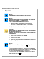
6.
Operation
NOTICE !
Check all external connections before starting to print.
NOTICE !
It is recommended to swing the applicator away from the printer
before loading the labels or the transfer ribbon.
Thus it is easier to do the appropriate handlings.
1.
Make sure that the media is loaded corresponding to the
instructions in the section 'Media Loading' of the Operator's
Manual Hermes.
2.
Attend that the pad is not covered by the label when switching on
the device.
CAUTION !
Attend that the slide valve at cylinder 1 is in the 'operate' position
by starting the labelling cycle.
Otherwise cylinder 1 can be moved without control. This fact can
cause damages.
3.
Switch on the power supply of the Hermes.
4.
Open the shutoff valve.
5.
Switch into the present mode of the Hermes during programming
and set the peel position to remove the labels from the carrier
ribbon to 3.5 mm.
NOTICE !
Before starting the first print job press the
key on the
printer.
This generates a synchronous running. Remove the processed labels
manually. After a few seconds the printer carries out a brief rewind and
the edge of the next label is positioned at the print line.
This synchronizing also has to be carried out when the print job has
been interrupted with the
30
key.
cab - Produkttechnik GmbH & Co KG
Tamp Applicator with Lift Cylinder Type 1300
6.
Start the print job.
7.
Start the labelling process via PLC interface.
If an error occurs while the applicator is operating, this is shown in the
display of the Hermes (for types of errors and how to treat them see
appendix B).
cab - Produkttechnik GmbH & Co KG
31
Tamp Applicator with Lift Cylinder Type 1300
This page is intentionally left blank.
32
cab - Produkttechnik GmbH & Co KG
Applicator - PLC Interface
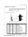
Appendix A - PLC Interface
For use in a networked system the applicator is equipped with a PLC
interface to start and interrupt the labelling process. It also passes on
state information as well as error messages of the applicator to the
system control.
The interface has a 15 pin SUB-D connector.
Pin Assignment of the PLC Interface
Fig. A-1
Pin 15
Pin 8
Pin 9
Pin 1
Connector of the PLC interface
PIN
Signal
Direction
Function
1
2
3
4
5
6
7
8
9
10
11
12
13
14
15
XSTRT
XSTP
XDREE
XDNB
XEDG
XSAA
XSOE
GND
XSTRTR
XSTPR
XDREER
XSUE
XETF
RÜL
24P
input
input
input
output
output
output
output
output
(input)
(input)
(input)
output
output
start signal
stop signal
print first label
printer not ready
no existing print job
general error message
pad in transition position
grounding (0V)
start signal (reverse line)
stop signal (reverse line)
print first label (reverse line)
pad in labelling position
applicator fault
reverse line (for all output signals)
operating voltage +24V, Si T 100mA
output
Table A-1 Pin Assignment of the PLC Interface
cab - Produkttechnik GmbH & Co KG
A-1
Applicator - PLC Interface
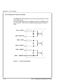
Circuit Diagrams of Input and Output
The inputs are optocouplers with a current limiting resistor of 2.4kW
in the input circuit.
For each signal X[IN] there is a separate reverse line X[IN]R via the
plug connector. From that, the following matching pairs of signals
result :
PIN1 - XSTRT
PIN9 - XSTRTR
PIN2 - XSTP
PIN10 - XSTPR
PIN3 - XDREE
PIN11 - XDREER
Fig. A-2
A-2
Circuit of the Inputs
cab - Produkttechnik GmbH & Co KG
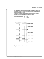
Applicator - PLC Interface
All outputs are realized through solid state relays which outputs are
connected among one another one-sided. The joint line is lead to the
plug connector as RÜL signal.
The switch function of the outputs is to open or close the contact
between the joint line RÜL and the respective output.
Electrical requirements :
Umax = 42V
Imax = 100mA
PIN4 - XDNB
PIN5 - XEDG
PIN6 - XSAA
PIN7 - XSOE
PIN12 - XSUE
PIN13 - XETF
PIN14 - RÜL
Fig. A-3
Circuit of the Outputs
cab - Produkttechnik GmbH & Co KG
A-3
Applicator - PLC Interface
Comments on the Signals
PIN1 - XSTRT - Start signal
The signal will release the start of the labelling process. It is active
when a current flows between PIN1 and PIN9.
PIN2 - XSTP - Stop signal
The signal is active when a current flows between PIN2 and PIN10.
It can release the following functions :
- to finish off the print of a label and its picking-up by the pad
- to interrupt or to stop the beginning of the labelling process
- to make the pad moving back into the starting position
- to command the disregard of all following signals
- if the stop signal has been activated during the labelling phase, the
display will show the message 'Host stop/ error'. (does not show
message during print process)
PIN3 - XDREE - Print first label
Within the operation mode 'Labelling / Printing', the current flow
between PIN3 and PIN10 activates the print of the first label and its
picking-up by the pad.
When the labelling process is started by the XSTRT signal within the
operation mode 'Labelling / Printing', the cylinder will start to place the
label onto the product at once. Only after that, a new label is printed.
Therefore, the provision of the first label has to be assigned by a
separate signal.
In the 'Printing / Labelling' mode this signal has no function.
PIN4 - XDNB - Printer not ready
This is an error message of the Hermes printer.
The details and type of error can be learnt from the printer display.
('Ribbon out'; 'Paper out'; 'No label')
In this state the contact between PIN4 and PIN14 is opened.
After error correction, the print of the last label will be repeated.
A-4
cab - Produkttechnik GmbH & Co KG
Applicator - PLC Interface
PIN5 - XEDG - No existing print job
State message.
There is no print job currently available.
In this state the contact between PIN5 and PIN14 is opened.
PIN6 - XSAA - General error message
General error message of both, printer and applicator.
This message is shown when one of the two errors either XDNB or
XETF occurs. This signal is important in case that only one error
signal of the applicator can be analysed from the system control.
In this state the contact between PIN6 and PIN14 is opened.
PIN7 - XSOE - Pad in transition position
The signal is active when the pad is in the transition position where
cylinder 1 is in its upper end position.
In this state the contact between PIN7 and PIN14 is opened.
PIN8 - GND - Grounding (0V)
PIN9 - XSTRTR - Reverse line of the start signal XSTRT
PIN10 - XSTPR - Reverse line of the stop signal XSTP
PIN11 - XDREER - Reverse line of the print first label signal XDREE
PIN12 - XSUE - Pad in labelling position
The signal is active when the pad is in its labelling position.
In this state the contact between PIN12 and PIN14 is opened.
cab - Produkttechnik GmbH & Co KG
A-5
Applicator - PLC Interface
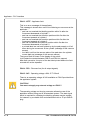
PIN13 - XETF - Applicator fault
This is an error message of the applicator.
This message is shown when one of the following errors occurs at the
applicator :
- pad has not reached the labelling position within 2s after the
movement downwards of cylinder 1
- pad has not reached the transition position within 2s after the
movement upwards of cylinder 1
- pad has not reached the transition position within 2s after the
movement upwards of cylinder 2
- pad has not leaved the transition position within 2s after the
movement downwards of cylinder 2
- a printed label has not been picked up by the pad properly or it fell
down during the movement of the cylinder (message of the vacuum
sensor)
- the label is still on the vacuum plate of the pad when the cylinder
moves back up (message of the vacuum sensor)
The type of fault is shown in the display of the printer.
In this state the contact between PIN13 and PIN14 is opened.
After fault correction, the print of the last label printed before the fault
occured will not be repeated.
PIN14 - RÜL - Reverse line (for all output signals)
PIN15 - 24P - Operating voltage +24V, Si T 100mA
There is an operating voltage of 24V available on PIN15 provided from
the applicator system.
CAUTION !
You must not apply any external voltage on PIN15 !
The operating voltage on the plug connector allows the use of the
applicator without being part of a networked system. The start signal
which is required for releasing the labelling process may be caused,
for instance, by a suitable foot controlled switch with a 15 pin SUB-D
plug.
A-6
cab - Produkttechnik GmbH & Co KG
Applicator - PLC Interface
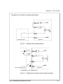
Examples for Circuits to Creating a Start Signal
24V
PIN15
PIN1
PIN9
Fig. A-4
GND
PIN8
Releasing Switch
Applicator
Example with releasing switch
brown
24V
PIN15
white/
black*
PIN1
PIN9
blue
PIN8
Sensor with pnp-output
GND
Applicator
* dependent on the used sensor
Fig. A-5
Example for an optical sensor with pnp-output
cab - Produkttechnik GmbH & Co KG
A-7
Applicator - PLC Interface
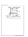
brown
24V
PIN15
PIN1
white/
black*
PIN9
blue
Sensor with npn-output
PIN8
GND
Applicator
* dependent on the used sensor
Fig. A-6
A-8
Example for an optical sensor with npn-output
cab - Produkttechnik GmbH & Co KG
Applicator - Error Messages
Appendix B - Error Messages
Error Messages of the Printer
Detailed information about printer errors (e.g. 'Paper out', 'Ribbon out',
etc.), their causes and correction methods can be found in the
Operator's Manual Hermes (Appendix C).
NOTICE !
With the installation of an applicator the error treatment expands.
This means in particular, that after correcting the error and before
the correction is quit with the
has to be released using the
key, an additional label feed
key. This synchronizes the
process of printing and labelling. Possibly dispensed blank
labels have to be removed manually.
After quitting the error message the label caused the error will be
printed once more.
Error Messages of the Applicator
The following table gives an overview of error messages and their
possible cause. It also suggests methods to resolve the problem.
After error correction, always quit the error message of the applicator
with the
key.
To reprint the label where the applicator error occurred, a new print job
has to be released.
cab - Produkttechnik GmbH & Co KG
B-1
Applicator - Error Messages
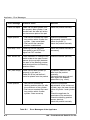
Error message
Possible cause
Solution
Label not depos.
Label has not been placed onto
the product; after cylinder 1 has
moved back the label still sticks
on the vacuum plate of the pad
Label the product manually
1. Pad has not reached the transition position within 2s after the
cylinder 1 has moved back
2. Pad has left the transition
position unauthorized
Check the pneumatic
adjustments (upper throttle
valve of cylinder 1);
Label the product manually
Upper position
Host stop / error
Labelling process has been
interrupted by an XSTP stop
signal via PLC interface
Label the product manually if
necessary
Refl. sensor blk.
There has been no change of the
switch state at the upper control
sensor (at the cylinder) between
the start of the labelling process
and the signal from the labelling
position sensor
Check the sensor (service)
Vac. plate empty
Label has not been picked up
properly by the pad; or
Label fell off the pad before it
could be placed onto the product
If possible, place the 'lost'
label onto the product
manually;
Otherwise stop print job and
start again with adapted
parameters (e.g. count)
Lower position
1. Pad has not reached the
labelling position within 2s after
the movement of the cylinder
2. Pad has not reached the transition position within 2s after
cylinder 2 has moved up
Table B-1
B-2
Check the pneumatic
adjustments of the concerned
cylinder (esp. the lower throttle
valve of cylinder 1 and cylinder
2);
Check the applicator for
heaviness of its mechanics;
Check the labelling position
sensor (service);
Label the product manually
Error Messages of the Applicator
cab - Produkttechnik GmbH & Co KG
Applicator - Function of the LEDs of the Electronics
Appendix C - Function of the LEDs of the Electronics
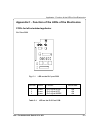
PCB's for left-orientated applicator
PLC Port PCB
1
3
2
Fig. C-1
LED on the PLC port PCB
LED No
Colour
Function
green
green
green
PLC signal XSTRT
PLC signal XSTP
PLC signal XDREE
1
2
3
Table C-1
Active state
ON
ON
ON
LED on the PLC Port PCB
cab - Produkttechnik GmbH & Co KG
C-1
Applicator - Function of the LEDs of the Electronics
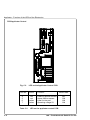
PCB Applicator Control
5
4
6
7
Fig. C-2
LED on the Applicator Control PCB
LED No
Colour
Function
red
red
yellow
yellow
Labelling position sensor
Upper position sensor
Label on the pad
Operating voltage 5V
4
5
6
7
Table C-2
C-2
Active state
OFF
ON
ON
ON
LED on the applicator control PCB
cab - Produkttechnik GmbH & Co KG
Applicator - Function of the LEDs of the Electronics
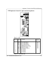
PCB Applicator Control for right-orientated applicator
1 2 3 11 10 9
4
8
5
6
7
Fig. C-3
LED on the PCB
LED-No. Colour
1
2
3
4
5
6
7
8
9
10
11
green
green
green
red
red
yellow
yellow
red
red
red
red
Function
PLC signal XSTRT
PLC signal XSTP
PLC signal XDREE
Upper position sensor
Labelling position sensor
Label on the pad
Operating voltage 5V
no function
no function
no function
no function
Active
state
ON
ON
ON
ON
ON
ON
ON
Table C-3 LED on the PCB
cab - Produkttechnik GmbH & Co KG
C-3
Applicator - Function of the LEDs of the Electronics
This page is intentionally left blank.
C-4
cab - Produkttechnik GmbH & Co KG
Tamp Applicator with Lift Cylinder Type 1300
Index
A
Air pressure 12
Applicator control 4, C-2
Applicator fault A-5
B
Blow tube 4f., 7, 15f., 22f.
C
CAN key (Hermes) 31
Compressed air supply 12
Connections 12, 30
Control valves 16
Copyright 2
Cover 26
Cylinder 4ff., 16ff., 22ff.
D
Delay times 26
DIP switches 22, 26, 28
Dispense edge 4, 13f.
E
Equipment supplied 7
Error messages B-1f.
Error messages applicator B-1f.
Error messages printer B-1
Errors 31
F
FF key (Hermes) 25, 31, B-1
G
General error message A-4
H Host stop / error A-3, B-2
K
Knurled screw 7, 10, 14
cab - Produkttechnik GmbH & Co KG
L
Labelling position 4, 6, 16, 22f., A-1f.
Labelling position sensor 4, 15f., C-2
Labelling pressure 15
Labelling / Printing 22, 28
Label not deposited B-2
LED C-1f.
Level adjustment 14
Lift cylinder 4f.
Locking time 27, 29
Lower position 4, B-2
M
Manifold 16, 24, 26
N
No existing print job A-4
O
ONL key (Hermes) 29
Operating pressure 12
Operation modes 22f., 26, 28
P
Pad 4f., 7, 13f., 16, 20ff., 30, A-3, A-5,
B-2, C-2
Pad in transition position A-1, A-4
Pad in starting position A-1, A-4
Peripheral port (Hermes) 9
PLC 30
PLC-connection C-1
PLC interface 4, 12, 22, A-1ff.
Pneumatic cylinder 4
Potentiometer 26f.
Pre-dispense key 24f.
Printer not ready A-1, A-3
Print first label A-1, A-3
Print info display 29
Printing / Labelling 22, 28
PSE key (Hermes) 29, B-1
Tamp Applicator with Lift Cylinder Type 1300
R
Reflective sensor blocked B-2
S
Safety instructions 7
Save settings 28
Sensor 4f., 22ff.
Service unit 7f., 11f.
Shutoff valve 8, 12, 20, 30
Signals (PLC) A-1f., C-1
Slide valve 20, 30
SPI interface 4
Start delay 27, 29
Starting position 4, 6, 13f., 22ff., 26f.,
A-1f.
Start signal A-1, A-3
Stop signal A-1, A-3
Supporting air 4, 15f., 21ff.
Switch-off delay supporting air 27, 29
Switch-on delay supporting air 27, 29
T
Technical data 6
Throttle valves 18, 21
Transition position 4, 6, 16, 22f., A-1,
A-5, B-2
U
Upper position 4, 16f., 20, 24, B-2
V
Vacuum
Vacuum
Vacuum
Vacuum
4, 16, 21ff.
nozzle 16
plate empty B-2
sensor 4
cab - Produkttechnik GmbH & Co KG
Tamp Applicator with Lift Cylinder Type 1300
cab-Produkttechnik
Gesellschaft für Computerund Automationsbausteine mbH & Co KG
Wilhelm-Schickard-Straße 14
D-76131 Karlsruhe
EC-Conformity Declaration
Herewith we declare that the following described machine, from the design and style
and as we sell it, complies with the relevant EC Safety and Health Requirements.
This declaration will lose the validity if there are any changes of the machine or the
purpose without our consent.
Description:
Applicator
Type:
Tamp Applicator
with Lift Cylinder Type 1300
Applied EC Regulations and Norms:
- EC Machinery Regulations
- Machine Safety
98/37/EU
EN 292-2:1991+A1:1995
- EC Low Voltage Regulations
- Data and Office Machine Safety
73/23/EEC
EN 60950:1992+A1:1993
EN 60950/A2:1993+A3:1995
+A4:1997
- EC Electromagnetic Compatibility Regulations
- Threshold values for the Interference
of Data Machines
- Limits for harmonic current emission
89/336/EEC
EN 55022:1998
- Limits of voltage fluctuation and flicker
- Immunity characteristicsLimits and methods of measurement
Signature for the producer:
cab Produkttechnik Sömmerda
Gesellschaft für Computerund Automationsbausteine mbH
99610 Sömmerda
Sömmerda, 01.10.01
Erwin Fascher
Managing Director
cab - Produkttechnik GmbH & Co KG
EN 61000-3-2:1995+A1:1998
+A2:1998+A14:2000
EN 61000-3-3:1995
EN 55024:1998