1
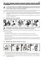
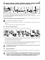
OPERATING INSTRUCTIONS MIX 30 - 109a MIX 30 - 309a Z15.051 0907 V02 ING PS Mixer US 2 English Mixer 3 Dear customer, we congratulate you for choosing a high quality product which will surely satisfy your expectations. With our thanks for choosing us, we kindly invite you to examine the present operating instructions manual before operating your new device. SUMMARY 1 2 IMPORTANT SAFETY SUGGESTIONS AND PRECAUTIONS ...................................................... 4 4 Technical data plate and CE marking .............. 5 Acoustic pressure level ................................... 5 7 4.2 Transportation of the packed device ................ 6 6 Unpacking ....................................................... 6 8 5.1 5.2 5.3 5.4 5.5 Placing and check of the parts ........................ 7 Device’s parts reassembling ............................ 8 Electrical connection ....................................... 8 Connection to the water network ..................... 9 Initial functioning check .................................. 10 Washing the tank accurately .........................16 Washing the impeller and tap accurately........16 Sanitizing ....................................................... 17 MAINTENANCE .....................................................17 8.1 INSTALLATION ...................................................... 7 Warnings ....................................................... 11 Controls and indicators .................................. 11 Heating and cooling mixing cycles .................13 Setting Up......................................................13 Production .....................................................14 Partial tap washing ........................................ 15 WASHING .............................................................16 7.1 7.2 7.3 CARRYINGAND UNPACKING ............................... 6 4.1 5 Lid's magnetic sensor ..................................... 5 TECHNICAL DATA .................................................. 5 3.1 3.2 DEVICE’S OPERATION ......................................... 11 6.1 6.2 6.3 6.4 6.5 6.6 SAFETY DEVICES .................................................. 5 2.1 3 6 8.2 8.3 9 Maintenance during the components disassembling ................................................18 Check of safety devices .................................18 Yearly maintenance .......................................18 PERIODS OF INACTIVITY ....................................19 10 MALFUNCTIONS .................................................. 19 WARNING: GENERAL/MECHANICAL DANGER DANGEROUS VOLTAGE DANGEROUS TEMPERATURE A TEXT IN UPPER-CASE, IDENTIFIED BY ONE OF THE SYMBOLS ABOVE, CONTAINS INSTRUCTIONS THAT, IF NOT FOLLOWED, MAY CAUSE HARM TO PEOPLE. A text in lower-case, identified by this symbol, contains instructions that, if not followed, could cause damages or malfunctions to the device, or falls in its quality. English Mixer 4 1 IMPORTANT SAFETY SUGGESTIONS AND PRECAUTIONS CAREFULLY READ THE INSTRUCTIONS CONTAINED IN THE PRESENT OPERATING INSTRUCTIONS MANUAL BEFORE INSTALLING AND OPERATING THIS DEVICE. THESE INSTRUCTIONS HAVE BEEN DRAFTED FOR THE SAFETY OF INSTALLATION, OPERATIONAND MAINTENANCE OF THIS DEVICE. The present manual of Operating Instructions, placed on the device in the packing and supplied with the Technical Handbook, the EC’s conformity certification and the electrical tests schedule, is an essential part of the mixer (also defined, in the present manual of operating instructions, simply with the term, device) and must be preserved for any future consultation. The technical handbook must always be given, together with the device, to the Assistance Service’s personnel or to the technicians, to whom you will eventually request assistance. In case of selling or transferring to other user, all the above mentioned documentation must be handed to the new user, so that he can be informed of the operation and relative technical information and safety instructions. RESIDUAL HAZARD: DURING THE HOT AND COLD MIXING CYCLES, THE PRODUCT BECOMES VERY HOT (+65...+85°C). SERIOUS HEALTH DAMAGE CAN BE CAUSED BY CONTACT WITH THE LID [5], THE TAP [11] AND THE DEVICE'S SURFACE [35] TOO. WHEN LID IS OPENED THE MACHINE STOPS, HOWEVER, THE MIXTURE REMAINS VERY HOT.PLEASE FOLLOW THESE RULES: Always check that the heating and cooling mixing cycles are completed or the product’s temperature, as shown on the display, is sufficiently low before opening the lid or the tap. Pay attention if an electrical power supply failure (or a blackout) occurs during a hot and cold mixing cycle, as the mixture’s temperature inside the tub could be still very high and the device thermometer would not be able to display it. If in doubt whether the mixture’s temperature is sufficiently low, do not open the lid or the tap, unless it is absolutely necessary. Should this occur, wear protective clothing (gloves, overalls, etc.), in order to avoid direct contact with the product. DO NOT INTRODUCE YOUR FINGERS OR OBJECTS IN THE DEVICE’S LOOPHOLES. DO NOT REMOVE OR HIDE, FOR ANY REASON, ANY LABEL APPLIED ON THE DEVICE. NEVER OPEN THE PROTECTING PANELS. THE DEVICE DOES NOT CONTAIN, IN ITS INSIDE, PARTS WHICH CAN BE OPERATED BY THE USER. THE USER MUST NOT EXECUTE OPERATIONS WHICH ARE NOT CLEARLY CONTAINED IN THE PRESENT USER’S MANUAL. ANY OPERATION WHICH REQUIRES TOOLS NOT GIVEN IN THE DEVICE’S EQUIPMENT IS TO BE CARRIED OUT ONLY BY THE ASSISTANCE SERVICE OR BY TECHNICALLY AUTHORISED PERSONNEL. Always unplug the device before undertaking any operation requiring access to the device’s moving parts (i.e. the beater). Any modifying of the electrical supply must be exclusively performed by professionally qualified and certified personnel. Any use of the machine other than heating and cooling mixture is considered improper. Do not connect and/or operate the device when any part is missing, except for specifically mentioned cases. The device has been made to be operated by adults, prohibit children to play with it. - avoid dispersing the freezing gas and the oil contained in the device; - carry out the draining and/or recycling according to the local provisions of the law currently in force on this matter. Modifying, or attempting to modify this device, can be dangerous and would void any type of warranty. Always use original spare parts. In the event of the use of the device being no longer required, deactivate the machine by severing the electric cable (after unplugging it from wall socket). In addition, follow these recommendations: English Operating instructions 2 5 SAFETY DEVICES DO NOT ALTER THE SAFETY DEVICES AND DO NOT UTILIZE THE MACHINE IF THE SAFETY DEVICES ARE DAMAGED OR MALFUNCTIONING. THE MANUFACTURER IS NOT RESPONSIBLE FOR POSSIBLE DAMAGES CAUSED TO PEOPLE OR OBJECTS BY THE ALTERING OR BYPASSING SUCH DEVICES OR RELATIVE CIRCUITS. 2.1 Lid's magnetic sensor This safety device, featuring an approved type magnet [1] and a magnetic contact [2] avoids accidents caused by the accidental starting of the beater when the lid is open. In consequence the device can't operate when the lid is open, and if it is opened during its functioning the beater immediately stops. In any case the lid's magnetic sensor MUST NOT be considered a control to be used for the normal stop of the device. DURING THE NORMAL USE, THE DEVICE MUST BE STOPPED ONLY BY USING THE BUTTONS ON THE CONTROL KEYPAD, AND NOT BY OPENING THE LID. The magnet [1] and the magnetic contact [2] must be assembled as follows: the grooves [3] and the stencilled semicircle [5] on the bottom of the magnet [1] must coincide with the grooves [4] (marked by a white line down the side) and the stencilled semicircle [6] on top of the magnetic contact [2]. The device will not work unless all parts have been correctly assembled in accordance with these instructions. 3 TECHNICAL DATA 3.1 Technical data plate and CE marking The technical data plate and CE marking must not be removed. It is placed on the back side of the device and identifies: - the name and address of the manufacturer [1]; - the designation of the model [2]; - the relative serial number [3] and the year of construction [4]; - the values of voltage and frequency [5]; - the type of cooling [6], the power [7] and current [8] consumption; - the type and quantity of freezing gas contained [9]; - the values of high and low pressure [10] and the CE marking [11]. 3.2 Acoustic pressure level The average equivalent continuous acoustic pressure level of this device is quoted in the Technical Handbook (Technical Data section). This data has been measured at 1 meter from the surface of the device and at 1.60 meters from groundlevel, during the device’s functioning. English Mixer 6 4 CARRYING AND UNPACKING Note: We suggest you to let the Assistance Service or qualified technicians carry out the transportation, unpacking and installation. TO LIFT THE DEVICE ALWAYS USE AN ADEQUATE LIFTING DEVICE. ATTEMPTING TO LIFT IT MANUALLY IS DANGEROUS AND CAN DAMAGE YOUR HEALTH. The device’s weight specifications, both inclusive of packaging and net, can be found in both the supplied documents and on the packaging itself. To prevent the oil contained in the compressor to flow into the refrigerating circuit, it is necessary to always keep the device in upright position, both during carrying and during the installation and operation. Always follow the instructions on the packing. 4.1 Transportation of the packed device The packing has been projected to assure at the device the highest protection. It is therefore suggested to transport the device while it is packed as near as possible at the place where it will be installed. To carry the packed device, use an elevator, or a bench trolley, inserting its forks in the basement’s holes. 4.2 Unpacking - WOOD PACKING: unnail the top panel, then separate the lateral panels. - CARDBOARD PACKING; cut the strips and remove the cardboard from the top; After having opened the packing, make sure the device isn’t damaged. In case of doubt, do not use it, and call the Seller. THE OPENING OF THE LATERAL PANEL IS ONLY ALLOWED TO THE ASSISTANCE SERVICE OR TO QUALIFIED TECHNICIANS AND MUST BE MADE BEFORE CONNECTING IT. MAKE SURE NOT TO DAMAGE THE INTERNAL PARTS OF THE DEVICE. English Operating instructions 7 - Remove both the lateral panels unscrewing the relevant fixing screws [21]; - Find and unscrew the bolts [22] which fix the device’s frame at the packing’s basement; The outlet of the supply cable is placed on the device’s lower side. During the lifting make sure not to damage it. - Lift the device from the basement, possibly working on the lower side, near the wheels, and however, only on the frame’s carrying parts. Remove the basement, and lean the device on the floor avoiding bumps; DO NOT insert objects, ropes or brackets for the lifting THROUGH the device, since these could damage the inside parts. - Re-close the lateral panels; - Replace or move the packing, which is produced with entirely recyclable materials ( 5 ). INSTALLATION THE INSTALLATION MUST BE CARRIED OUT ONLY BY THE ASSISTANCE SERVICE OR BY TECHNICALLY AUTHORISED PERSONNEL AND IN COMPLIANCE WITH THE LAWS IN FORCE, ALWAYS FOLLOWING INSTRUCTIONS OF THE MANUFACTURER. 5.1 Placing and check of the parts Place the device on the floor, on a flat and steady surface. Install the device away from any source of heat, avoiding a direct exposition to sun radiation and making sure that air can freely circulate around each side of the device itself. The devices with AIR CONDENSING need at least a 20'' (50cm) free space in front of the condenser’s grill, to assure the refrigerating plant correct functioning. Further information are reported on the Technical Book (Technical Data section). Check that all of the listed components are present: - Lid [5]; - Drip tray [26] with bracket [27]; - Tap [11] including: inner body [12]; piston [13]; cover [14], lever [15]; fastening knob [16]; - all the technical documentation (in addition to this handbook): the Technical Handbook, the EC’s Conformity Certification and Electrical Test’s Schedule. English Mixer 8 5.2 Device’s parts reassembling - Before inserting the tap, turn the lever [15] fully to the LEFT (OPEN position). Failing to do so might prevent the tap from fully inserting in the slot; - Ease (do not fully unscrew it) knurled fastening knob [16]; - If necessary, lubricate the piston’s end [13], inside the slot [3], and their gaskets, with food-compatible grease (i.e. vaseline); - Fully insert [11] into the slot [3] and tighten fastening knob [16]; Check that the knob’s head [16] is correctly and firmly fixed in the slot [3], as to avoid damage to the gaskets and subsequent leakages. - Turn tap’s lever fully to the RIGHT (CLOSED position). Check that there is no excessive strain on the part. - Install drip tray [26] (with its bracket [27]) onto the front panel. 5.3 Electrical connection THE SUPPLY’S VOLTAGE REQUIRED BY THE DEVICE IS HIGH, SO, IT IS PARTICULARLY DANGEROUS. THE WORKS ON THE SUPPLY’S ELECTRIC CIRCUITS MUST BE MADE WORKMANLIKE BY QUALIFIED STAFF. THE ELECTRIC SAFETY OF THIS AUTOMATIC DEVICE IS REACHED ONLY WHEN THE SAME IS CORRECTLY CONNECTED, BY QUALIFIED AND CERTIFIED PERSONNEL, TO AN EFFICIENT EARTHING SYSTEM, MADE AS PROVIDED FOR IN FORCE SAFETY REGULATIONS. The manufacturer must not be considered responsible for eventual damages caused by an inadequate electric or earthing system. All the electric device's features required for the system’s proportioning are reported on the Technical Data Plate and on the Technical Handbook. FOR PREPARING THE ELECTRIC SYSTEM WHICH SUPPLIES THE DEVICE, IT IS COMPULSORY TO FOLLOW THE PRESCRIPTIVE STANDARDS IN FORCE. IN PARTICULAR: - The electric capacity of the system must exactly match the supply’s voltage and frequency required by the device; - the current capacity of the system must be suitable for the device’s input; - the system must end with an accepted 4 pole electric socket and with electric and mechanical suitable characteristics. The electric socket’s poles must be marked with appropriate letters (phases R-S-T + earth); the earth’s pole must be recognizable; - the electric socket must prevent, through appropriate mechanical measures, the plug’s wrong connection; - the electric socket must have, above or annexed, a breaker, conformed to the in force safety laws, with an associated gearing placed near the device, in a position easily reachable by the operator. It must also be protected by fuses, above or annexed, with characteristics suited at the current absorbed by the device. A WRONG CONNECTION ON THE EARTH TERMINAL MAY CAUSE SERIOUS DANGER. English Operating instructions 9 A 4 pole plug, suitable with the current socket, must be installed at the end of the device's power supply cable. The device’s power supply cable is composed by 3 or 4 coloured wires, and eventually marked with appropriate bands, which must be connected to the relevant plug’s terminals, as shown in the following table. A WRONG CONNECTION IN THE PLUG’S INSIDE MAY CAUSE SERIOUS DANGER. FOR THE CONNECTION, ONLY ADDRESS YOUR SELVES TO QUALIFIED AND AUTHORIZED TECHNICIANS. Kind of supply Wire colour Wire marking band Code marked near plug’s terminal EARTH GREEN None Phase R BLACK R or L1 Phase S RED S or L2 Phase T WHITE T or L3 PE or Before using the device it is necessary to: - connect it to the water network, if the device features a water condenser (Ref. Par. 5.5); - carry out the initial functioning checking (Ref. Par. 5.6). 5.4 Connection to the water network If your machine is provided with an AIR condenser, only water INLET pipe is necessary (for washing operations); in case the machine is provided with a WATER condenser, both INLET and OUTLET pipes are necessary. FOR THOSE MACHINES PROVIDED WITH A WATER CONDENSER: Do not let water from a TOWER in, unless they have been specifically designed to utilize water from a tower. Unless otherwise specified, the machine is designed to utilize water from a WELL. Note: In the “Technical Data” section of the Technical Handbook you will find the necessary specifications regarding the water’s correct temperature in order to operate the machine. The use of below standard tubes and connections may cause water drops, with consequent inconvenience for Your laboratory and, if the drop is abundant with squirts, damage the device. Use linen-rubber tubes for water connection, arranged for 218 PSI (15 bar), interposing a valve or a faucet [B] ABOVE the delivery pipe; use a 3/4" rubber holder [C], well fixed with a proper band [D] to connect the tubes at the device’s union. Note: Tubes for the water feeding of households are on the market (ex. dishwashers) which, in addition to being cheap, feature the requested characteristics and are predisposed with a rubber holder. Pipe unions are placed on the machine's rear panel, they are labelled IN: [A] and marked: fresh water INLET OUT: waste water OUTLET Pipe unions for washing extraction tap [E] are placed on the machine,s rear panel. English Mixer 10 Follow the following precautions to avoid damages at the device’s water circuit: - do not invert the connection of tubes; - if water in the area presents a high quantity of spur, install a suitable decalcification or filtration device above the delivery pipe (IN marked); - if not otherwise mentioned in the Technical Handbook, the incoming water’s pressure must be comprehended between 22 Psi (1,5 Bar) and 87 Psi (6 Bar), (ideal pressure 41 Psi- 3 Bar). If the pressure in the device is higher, it is necessary to interpose a pressure limiting device, appropriately regulated, above the delivery pipe. AVOID CONSTRICTION OR NARROW TURNS OF THE TUBES. Note: The water outcoming the condensator, though being hot and not drinkable, is not polluted and can be reutilised. Before storing the device in rooms with a temperature lower to 32 °F (0°C) it is INDISPENSABLE to get rid of the water in the condensator (with WATER condensation) and in the inlet, outlet and washing pipes. Call the Assistance Service. 5.5 Initial functioning check At the end of the installation, and before utilising the device, it is indispensable to let a qualified technician check the correct connection, by performing the following procedure. - Before proceeding, check that the socket's Main switch is in position "0"; - insert the plug and turn the Main switch to position "1": only the green lights of the START button [Z1] should light up on the control panel; - close the lid and press the START button [K1]. The machine prepares to operate and tank temperature appears on the display; Note: - press the SLOW BEATING ACTION button [K4] and observe BEATER rotation. If it is ANTICLOCKWISE (as shown in the drawing) the machine is connected correctly and is ready for use; Note: - if the display shows “ooo" (three small squares), the lid is not correctly closed. If so, the device cannot start. do not unnecessarily start the heating or cooling mixing cycle. if rotation is in a CLOCKWISE direction, three-phase connection voltage is wrong and must be modified as follows: English Operating instructions 11 - Turn off the device by pressing ON/OFF [K1]; TURN THE SOCKET’S MAIN SWITCH TO POSITION "0" AND PULL OUT THE PLUG; 6 6.1 - Open the plug’s shell and invert TWO of the THREE conductors connected at the phases (R-S, R-T or S-T); - Close the plug’s shell, plug in the device and repeat the check. DEVICE’S OPERATION Warnings WHEN USING THE DEVICE, AS WITH ALL ELECTRICAL APPARATUS, ESSENTIAL RULES MUST BE COMPLIED WITH, PARTICULARLY: - never touch it if your feet or hands are wet; - never operate it while barefoot; - never pull the supply cable to disconnect it from the mains network; - avoid liquids to penetrate in the device, for example during its cleaning; - forbid children and unable people to operate it. In case of failure and/or malfunctioning of the device - and every time you notice damages, mainly at the supply cable or at the safety devices - switch it off from the main breaker and unplug it. Contact qualified and certified personnel for assistance. NEVER operate the machine in DRY conditions or with an amount of mixture other than the one recommended. The beater is designed to shift liquids, NOT to grind solids. NOT RESPECTING THESE RULES, IN ADDITION TO VOIDING ANY FORM OF WARRANTY, CAN SERIOUSLY COMPROMISE THE SAFETY, PERFORMANCES AND FUNCTIONING OF THE SAME DEVICE. 6.2 Controls and indicators All controls and indicators for the use of the device are grouped in a single control panel placed on the frontal panel. Its functioning is electronically managed in low voltage. In this manual, the buttons and indicators are identified with the relative symbol, and/or with an imprint ([K…] for pushbuttons, [Z…] for indicators). The functioning of every control is described hereby: to obtain the best results, an acknowledgment is suggested. ON/OFF Pushbutton [K1] When the electric supply is connected, the machine is ready to be turned on, the green indicator [Z1] is on. When pressing [K1], the machine is on, a short electronic test is performed and the other pushbuttons are enabled. The display shows the temperature inside the tub, in °C. English Mixer 12 ADJUSTMENT Pushbuttons [K2] - [K3] These pushbuttons are enabled only after pressing SET UP [K8]. They increase or decrease set values. For more details on their use, see Par. 6.4 “Setting Up”. MANUAL BEATING Pushbutton [K4] When pressing the pushbutton, its indicator [Z4] goes on and the beater starts operating CONTINUOUSLY. When pressing the pushbutton again, the beater stops and the indicator goes out. HIGH HEATING TO 85 °C (185 °F) Pushbutton [K5] When pressing, a full automatic High Temperature heating and cooling mixing cycle commences. On completion, the machine enters the Preservation mode. For more details see Par. 6.3. “Heating and cooling cycles”. The indicator [Z5] remains on for the entire duration of the cycle. LOW HEATING TO 65 °C (149 °F) Pushbutton [K6] When pressing, a full automatic Low Temperature heating and cooling mixing cycle commences. On completion, the machine enters the Preservation mode. For more details see Par. 6.3 “Heating and cooling cycles”. The indicator [Z6] remains on for the entire duration of the cycle. MANUAL REFRIGERATION/PRESERVATION Pushbutton [K7] When the pushbutton’s indicator [Z7] is on, the machine is in preservation mode: the mixture inside the tub is maintained at a temperature of approximately 4°C (39 °F) (or the final preset temperature). The beater, starting at the same time as the refrigerator, shifts the mixture to maintain it homogenous and to maintain the temperature uniform. Press the pushbutton to manually turn on (indicator on) or off (indicator off) the Preservation mode, to stop heating stage during heating and cooling mixing cycle. SET UP Pushbutton [K8] When pressing, the display shows the heating and cooling mixing cycle’s main settings. Should the need arise to modify them, press ADJUSTMENT [K2] and [K3]. For more details see Par. 6.4 “Setting Up”. WASH Pushbutton [K9] When pressing, the automatic washing of the tap commences. See also Par. 6.7 “Washing the tap”. Digital Display When turning on and during regular functioning, the display always shows the temperature inside the tub (together with that of the mixture inside); - During setting up, the display shows current settings; - If it shows “ooo ” (three small squares), the lid is either open or incorrectly closed. English Operating instructions 6.3 13 Heating and cooling mixing cycles The total cycle lasts approximately 90…100 minutes and varies according to the mixture quantity, type and thickness. High heating and cooling mixing cycle This is a high temperature thermic cycle, devised for those ingredients requiring such procedure. The machine heaths the mixture to the required temperature [Ta] (between 80°C / 176 °F and 90°C / 194 °F), then chills it to the required Preservation Temperature [Tca]. Low heating and cooling mixing cycle This is a lower temperature but extended thermic cycle, devised for delicate ingredients. The machine heaths the mixture to the required temperature [Tb] (between 60°C / 140 °F and 70°C / 158 °F) and maintains this temperature for 30 minutes. The mixture is then chilled to the required Preservation Temperature [Tcb]. 6.4 Setting Up The machine has been adjusted during testing with optimal settings. Do not modify settings unless strictly necessary. Note: - Set up the machine when not in function, before starting production. Press ON/OFF [K1], the machine is now on. Press SET UP [K8]. On the display “P1” will flash, showing that you are now in SET UP mode and can proceed to set up the required temperature for the High heating and cooling mixing automatic cycle; Note: If you wait longer than 7…8 seconds without pressing any pushbutton, any new setting will be automatically stored and the SET UP mode will terminate. - press SET UP [K8] again. The display shows the High heating and cooling mixing temperature [Ta]. If required, adjust temperature by pressing ADJUSTMENT [K2] or [K3]. The manufacturer’s settings is +85°C. The adjustment range is +80°C…+90°C; - press SET UP [K8] again. The display shows the preservation temperature at the end of the automatic High heating and cooling mixing cycle [Tca]. If required, adjust temperature by pressing ADJUSTMENT [K2] or [K3]. The manufacturer’s setting is +4°C (39 °F). The adjustment range is +1°C (34 °F)…+6°C (43 °F); English Mixer 14 - press SET UP [K8] again. On the display “P2” will flash, showing that you can proceed to set up the required temperature for the Low heating and cooling mixing automatic cycle; - press SET UP [K8] again. The display shows the Low temperature [Tb]. If required, adjust temperature by pressing ADJUSTMENT [K2] or [K3]. The manufacturer’s setting is 65°C (149 °F). The adjustment range is +60°C (140 °F) …+70°C (158 °F); - press SET UP [K8] again. The display shows the preservation temperature at the end of the automatic Low heating and cooling mixing cycle [Tcb]. If required, adjust temperature by pressing ADJUSTMENT [K2] or [K3]. The manufacturer’s setting is +4°C. The adjustment range is +1°C…+6°C; - when you press SET UP [K8] again (or wait for a few seconds), the settings are stored, the SET UP mode terminates and the machine is ready to be used. 6.5 Production In devices with water condensation, check that the condensation water’s faucet is open; - Before beginning the production, wash, rinse and proceed at the hygienisation with a detergent and disinfecting solution (see section 7 - WASHING). Note: If you plan to have more than one consecutive production cycles, you can avoid the washing between a cycle and the other, making sure you begin with the clearer mixtures. - check that the START light [Z1] is on. If not, check that the plug has been inserted properly and that the Main switch is in position "1"; - check that the lid is closed, otherwise the device will not operate; - press ON/OFF [K1]. - check that the mix extraction tap is well turned off (turned completely towards the right) and transfer the mix into the tank. MAXIMUM tank capacity is 30 litres, recommended MINIMUN quantities are generally: - 1/4 of maximum capacity during heating and cooling mixing; - 1/5 of maximum capacity during preservation. Too little mixture can cause excessive overheating or the development of ice and cause damage or irregular squirts and foam during production; too much mixture can slow down or not complete the process of heating and cooling mixing cycles and cause overspills. - add ingredients to be heat and cool with the mixture; - close lid; if you require to pre-blend the ingredients, operate whipper by pressing MANUAL BEATING [K4], when ready, press it again, to stop whipper; English Operating instructions - 15 start required for heating and cooling mixing cycle by pressing HIGH [K5] or LOW [K6] temperature cycle; RESIDUAL HAZARD: DURING HEATING, THE PRODUCT BECOMES VERY HOT (+65 / 149 °F...+85°C / 185 °F ). SERIOUS HEALTH DAMAGE CAN BE CAUSED BY CONTACT WITH THE LID [5], THE TAP [11] AND THE DEVICE'S SURFACE [35] TOO. WHEN LID IS OPENED THE MACHINE STOPS, HOWEVER, THE MIXTURE REMAINS VERY HOT. IS THEREFORE RECOMMENDED THAT YOU ALWAYS CHECK THAT HEATING AND COOLING MIXING CYCLE IS COMPLETED OR, IN ANY CASE, THAT DISPLAY SHOWS A SUFFICIENTLY LOW TEMPERATURE BEFORE OPENING LID OR TAP. - wait until production is completed. This is indicated when HIGH or LOW TEMPERATURE CYCLE indicators [Z5] or [Z6] go out and PRESERVATION’s indicator [Z7] is on. The display will show the Preservation temperature. Note: On completion of the cycle, the machine maintains mixture at the preset temperature, provided that lid is correctly closed and PRESERVATION’s indicator [Z7] is on. In case ingredients need adding to the mixture: - press correct pushbutton to stop cycle in progress and open the lid; - add ingredients and close the lid; - press the same pushbutton to start cycle. When the mixture is ready to be dispensed: - turn drip tray [26] sideways and place suitable container beneath the tap; - open the tap turning the handle to the left in order to release the required amount of mixture. Close the tap and relocate drip tray beneath it. In case all of the mixture is extracted, turn machine off. In case less than 1/4 of the mixture remains in the tub, it is recommended to remove all of it and put in the refrigerator, as it could cause foam or squirts. 6.6 Partial tap washing Immediately following an extraction of mix (however small), all trace of the mix must be removed from the inside of the tap. Note: partial washing is carried out with the tap off. Place a container under the extraction tap and press the WASH button [K9]. Allow the water to run until it is clear. Then stop the process by pressing the WASH button [K9] again. English Mixer 16 7 WASHING THE FATS CONTAINED IN THE ICE-CREAM MIXTURES ARE IDEAL FOR THE GROWTH OF BACTERIA, WE RECOMMEND TO WASH AND CLEAN WITH THE MAXIMUM CARE EVERY PART IN CONTACT WITH PRODUCT, WHEN THE USE OF THE DEVICE IS SUSPENDED. In accordance with present hygiene norms, all parts of the machine which come into contact with the product must be accurately washed. During washing, all removable components must be disassembled and washed separately. Note: Additionally to the operations mentioned in this Chapter, it is recommended to clean machine’s outer panels and all of its outside parts, taking particular care to clean drip tray [26] and its bracket [27], after removing them from the front panel. For a long life of the device we suggest not to use too hot water, solvents, abrasive detergents, or rough sponges, in particular on the plastic parts. 7.1 Washing the tank accurately WASHING MUST THE CARRIED OUT ONLY WHEN THE MAIN SWITCH IS IN POSITION "O". DO NOT ALLOW WATER OR OTHER LIQUIDS TO PENETRATE THE MACHINE OR ITS MOTORS When production is completed, if the machine is not in use, even for a period of a few hours, all traces of mixture must be removed from all surfaces. - Check that tap is closed; - open lid and pour warm water (2 gallon at 104°F)and FOOD-COMPATIBLE detergent (2 oz) in the tank; - wash the entire tub’s surface, the lid, the beater’s shaft and whipper using disposable material or suitable brush; - before emptying the tank - place container beneath the tap and open it to empty the tank, press the start button and run machine for 3 minutes; - repeat operation with clean water (at room temperature) and, with the tap still open, press the tap wash button until the water comes out clear. 7.2 Washing the impeller and tap accurately - Extract the plug [20] and pull out the impeller [7] from the beater shaft [6]; - Each component must be washed using a suitable brush in a solution consisting of 2 oz of detergent suitable for use with food preparation equipment in 2 gallons of hot water (104°C). Rinse each part using water at room temperatures. Note: To simplify maintenance, all of the tap’s components can be dismantled by the operator, quickly and effortlessly, without the aid of any tool. English Operating instructions 17 - Turn lever [15] to the LEFT to open tap; - ease knurled fastening knob [16] and remove tap from slot [3]; - remove lever [15] and remove cover [14]; - remove piston [13] from tap’s inner body [12]; - remove gaskets [G] (see Par. 8.1); - Each component mentioned in points 6-7 must be washed using a suitable brush in a solution consisting of 2 oz of detergent suitable for use with food preparation equipment in 2 gallons of hot water (104°F). Rinse each part using water at room temperature. Note: The gaskets must be periodically replaced (ref. Par. 8.1). 7.3 Sanitizing - Prepare a solution consisting of 2 oz of Spartan Chemical SANI-T-10 disinfectant in 2 gallons of water at room temperature. Immerse all the components mentioned in Par. 7.2 in this solution for 5 minutes. - Remove the components from the solution; lubrificate the seals and the inner surfaces of the tap joint using grease suitable for use with food preparation equipment. Re-asemble all the sanitized parts in their original positions. - Pour a solution consisting of 2 oz of Spartan Chemical SANI-T-10 disinfectant in 2 gallons of water at room temperature into the tank. Clean all the tank surfaces and the lid, using disposable sterile material or suitable brush. Press the stir button and allow the machine to run for 5 minutes before emptying the tank. - Rotate the spillage collector to one side, position a container under the tap and open it to empty the tank. - The machine should be rinsed first with a disinfectant solution and then with the drinking water, ensuring that the correct hygiene procedures are observed, in accordance with national or local regulations. - Each time the machine is cleaned, it must be sanitized, using sterile gloves. Sanitization must be carried out on a regular basis, in accordance with local hygiene regulations. 8 MAINTENANCE The device requires a very limited maintenance. Periodically, we suggest to: - check the good state of the parts of the device. The disassembly, for example during the accurate washing, is an ideal opportunity for a similar check (ref. Par. 8.1); - check that electric power cable, pipe fittings (rubber holder) and water pipes are not damaged; - Try the efficiency of the safety disposals (ref. Par. 8.2). It is then useful to maintain the external panels clean and the surrounding area. Dust, paper fragments or other small objects may penetrate in the device through the ventilation loopholes (in particular if equipped with air condensation and rapidly compromise its correct functioning. The inside parts, to which the user MUST NOT accede, must be checked by the Assistance Service (ref. Par. 8.3) English Mixer 18 8.1 Maintenance during the components disassembling Check the integrity of gaskets (indicated with [G] in the figure) and substitute those that are deteriorated. Use exclusively original gaskets realised with food rubber. The spare bag contains a complete series of gaskets approved by the manufacturer. A replacement of all gaskets once every year is suggested. We suggest you to always keep a spare supply: to order it, reference to the Spares Section contained in the Technical Handbook. To correctly replace the gaskets it is necessary to: - remove old gaskets with an appropriate tool, possibly non- metallic, paying attention not to damage them or their seatings; - lubricate new gaskets with food- compatible grease before replacing. 8.2 Check of safety devices Periodically, check the efficiency of all the safety devices, carrying out the following check: - turn off the machine by pressing the START button [K1]. Turn the Main switch to position "0". If the Main switch functions properly, the START command light [Z1] will turn itself off; - close the lid and turn the main switch to position "1"; - press ON/OFF [K1] and then MANUAL BEATING [K4] (the beater’s shaft will start). Open the lid. If the lid’s magnetic sensor is functioning correctly, the beater’s shaft will stop and the display will show 3 small squares. If the machine’s functioning is as described, the safety devices are efficient. THE MACHINE MUST NOT BE USED IF ONE OR MORE OF THE SAFETY DEVICES SHOULD RESULT DAMAGED OR MALFUNCTIONING! 8.3 Yearly maintenance Periodically (basing yourself on the environmental conditions in which the device operates) and in any case once every year, make sure to have a general checkup. THE CHECK-UP MUST BE MADE BY THE AUTHORISED ASSISTANCE SERVICE, OR, IN ANY CASE, BY TECHNICALLY AUTHORISED PERSONNEL WITH ADEQUATE TOOL. THE MAINTENANCE OPERATIONS RESERVED TO THE SERVICE ASSISTANCE CAN BE DANGEROUS IF CARRIED OUT BY NON-PROFESSIONALS, THEREFORE, FOR HIS OWN SAFETY, THE USER MUST NEVER CARRY THEM OUT. English Operating instructions 9 19 PERIODS OF INACTIVITY If long periods of inactivity are foreseen, proceed as follows: - wash up completely the device (see Chapter 7); - switch off the socket's breaker and unplug the device; - check that the Main Breaker is on the “0” position; - close the water faucet and relieve pressure from inside the delivery pipe by unscrewing one of the pipe fittings. Remove both delivery and drain pipes and let all water out. Before using the pipes again, following a long period of inactivity, check for any damages or cracks and replace, if necessary, pipe fittings’ gaskets. - if the device will be stored in a different place, group all the documentation, together with the present manual, and enclose it at the device (for example inside the tub). Before storing the device in rooms with a temperature lower to 0°C (32°F) it is INDISPENSABLE to get rid of the water in the condensator (with WATER condensation) and in the inlet, outlet and washing pipes. Call the Assistance Service. 10 MALFUNCTIONS WE RECOMMEND YOU TO CALL IMMEDIATELY THE ASSISTANCE SERVICE IF A MALFUNCTION DIFFERENT FROM THOSE HERE DESCRIBED IS FOUND. Note: the following malfunctions do not refer to problems noticed in the installation phase, but ONLY on correctly installed - and already functioning - devices. THE DEVICE DOES NOT SEEM TO BE WORKING AT ALL. With the Main Breaker on 1 the ON/OFF indicator [Z1] DOES NOT TURN ON. Cause: The plug is not correctly plugged. The socket is defective. A qualified technician should substitute it. Power in the socket is missing. Check that the Main Switches, the breakers and the differentials (lifesavers) on the electric plant are closed. If they aren’t, before closing them, make sure that no one is making electrical maintenance. A protective fuse of the electric plant is cut down. Find and eliminate the eventual cause of overcharge. Substitute cut down fuses with others of the same kind. The supply cable is defective. BEFORE, cut down electrical feeding at the socket by opening the breaker above it, then disconnect the plug and call the Assistance Service. DO NOT TOUCH THE DAMAGED ELECTRICAL CABLES BEFORE HAVING CUT DOWN THE ELECTRICAL SUPPLY! With the Main Breaker on 1 the ON/OFF indicator [Z1] TURNS ON, but the display shows 3 small squares and the device does not work. Cause: The lid is not correctly closed or tends to open; The lid’s magnet is damaged. Call the Assistance Service. The lid magneto has been positioned incorrectly. Call the Assistance Service THE MAGNETIC CONTACT AND THE RELATIVE MAGNET ARE IMPORTANT SAFETY DISPOSALS! English Mixer 20 With the Main Breaker on 1 the ON/OFF indicator [Z1] TURNS ON, but the device does not work. Cause: Break down of inside parts or at the electronic controls. Call the Assistance Service. THE DEVICE CAUSES REPEATED RELEASES OF THE ELECTRICAL PROTECTIONS OR THE INTERRUPTION OF FUSES. Cause: The capacity of the electrical plant is not sufficient to feed the device. The electrical characteristics of protections and fuses are not adequate. Inside breakdown of the device. Call the assistance service. THE REFRIGERATION IS INSUFFICIENT OR DISACTIVATES IN AN ANOMALOUS WAY. Cause: The thermical protection of the compressor has been activated, due to excessive stress (repeated startings, high pressure, overheating). Stop the device, wait a few minutes and try starting again. If the device doesn't work or inconvenient frequently repeat, call the assistance service. Note: it may be necessary to wait up to 30 minutes for the thermal protections to cool down. WATER CONDENSATION Cause: The flow of condensation water is interrupted or insufficient. The water tubes present constrictions. Avoid constrictions or narrow turns. The water condensation faucet/s are partially or totally closed. The static pressure valve must be newly regulated, otherwise it is broken. Call the Assistance Service. Note: To check if the water correctly flows and if the static pressure valve is regulated, it is sufficient to temporarily detach the water outlet tube (at the end not connected at the device). Water must flow only when the refrigerating plant is in function. The incoming water’s temperature is higher than that prescribed in the Technical Handbook. Cause: The compressor is overheated due to a lack of ventilation. Clean the loopholes and restore the minimal distances for the circulation of air at the sides of the device. Note: It may be necessary to wait up to 30 minutes for the thermal protections to cool down. Break down at the refrigerating plant, or at the electrical controls. Call the Assistance Service. English Operating instructions 21 UNUSUAL NOISINESS. The noise comes mainly from the tank, when beating is on. Cause: There are solids or heavy sediments inside the tank or on the beater. Stop the machine, wait until mixture has cooled down, empty the tank and remove them. The beater’s motor is damaged. Call Assistance Service. The noise does NOT come from the tank, but is heard even when no beating is on. Cause: Inside break down. Call the Assistance Service. ALARM CODE The Display shows an alarm code P – – / PEE TAKE THE POWER SUPPLY OFF at once by the Main Breaker. Note: Alarm signals are unusual but possible under special circumstances. Before deciding that machine is out of order, switch machine off for as long as it takes to normalize temperatures (30...60 minutes), turn back on and check for alarm signals. Alarm code “P – –”: the TANK's temperature probe detects a temperature HIGHER than the safety limits. Note: If a very high TEMPERATURE is programmed (see par. 6.3, P1 programming) the alarm may go ff (this occurs, however, only in certain circumstances). Cause: Machi e is running dry or product in the tank is insufficient. Restore minimum quantity of product. Cause: The tank temperature probe is broken (interrupted or out of tolerance range). Call Assistance Service. Alarm code “PEE”: the TANK's temperature probe detects a temperature LOWER than the safety limits. Cause: The tank temperature probe is broken (due to a short circuit) or wiring is damaged. Call Assistance Service. Cause: The control circuits can't take the power supply off to the compressor (it is kept on). Relevant power relay has likely locked. Call the Assistance Service. Cause: The tank temperature probe is broken (cut off or out of range). Call Assistance Service. English Mixer 22 ROSS & TELME PRODUCT LINE WARRANTY 1. Scope: Stoelting, LLC warrants to the first user (the “Buyer”) that the freezing cylinders, hoppers, compressors, drive motors, speed reducers, beaters and agitator of Stoelting batch and custard freezers will be free from defects in materials and workmanship under normal use and proper maintenance appearing within two (2) years, and that all other components of such equipment manufactured by Stoelting will be free from defects in material and workmanship under normal use and proper maintenance appearing within twelve (12) months after the date that such equipment is originally installed. 2. Disclaimer of Other Warranties: THIS WARRANTY IS EXCLUSIVE; AND STOELTING HEREBY DISCLAIMS ANY IMPLIED WARRANTY OF MERCHANTABILITY OR FITNESS FOR PARTICULAR PURPOSE. 3. Remedies: Stoelting,’s sole obligations, and Buyer’s sole remedies, for any breach of this warranty shall be the repair or (at Stoelting’s option) replacement of the affected component at Stoelting’s plant in Kiel, Wisconsin, or (again, at Stoelting’s option) refund of the purchase price of the affected equipment, and, during the first twelve (12) months of the warranty period, deinstallation/reinstallation of the affected component from/into the equipment. Those obligations/remedies are subject to the conditions that Buyer (a) signs and returns to Stoelting, upon installation, the Checklist/Warranty Registration Card for the affected equipment, (b) gives Stoelting prompt written notice of any claimed breach of warranty within the applicable warranty period, and (c) delivers the affected equipment to Stoelting or its designated service location, in its original packaging/crating, also within that period. Buyer shall bear the cost and risk of shipping to and from Stoelting’s plant or designated service location. 4. Exclusions and Limitations: This warranty does not extend to parts, sometimes called “wear parts”, which are generally expected to deteriorate and to require replacement as equipment is used, including as examples but not intended to be limited to o-rings, auger seals, auger support bushings and drive belts. All such parts are sold AS IS. Further, Stoelting shall not be responsible to provide any remedy under this warranty with respect to any component that fails by reason of negligence, abnormal use, misuse or abuse, use with parts or equipment not manufactured or supplied by Stoelting, or damage in transit. THE REMEDIES SET FORTH IN THIS WARRANTY SHALL BE THE SOLE LIABILITY STOELTING AND THE EXCLUSIVE REMEDY OF BUYER WITH RESPECT TO EQUIPMENT SUPPLIED BY STOELTING; AND IN NO EVENT SHALL STOELTING BE LIABLE FOR ANY INCIDENTAL OR CONSEQUENTIAL DAMAGES, WHETHER FOR BREACH OF WARRANTY OR OTHER CONTRACT BREACH, NEGLIGENCE OR OTHER TORT, OR ON ANY STRICT LIABILITY THEORY. September 1, 2006 Form 721-053, Rev. 0 English Operating instructions 23 COSTRUTTORE: CONSTRUCTEUR: CONSTRUCTOR: Servizio Assistenza: Service d’Assistance: Servicio Asistencia: MANUFACTURER: HERSTELLER: FABRIKANT: Technical Service: Kundendienst: Servicedienst: