1
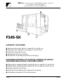
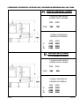
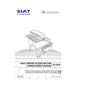
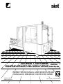
siat
®
AUTOMATIC CASE FORMER F145-SX
FORMATORE AUTOMATICO PER CASSE IN CARTONE F145-SX/ML
INSTRUCTIONS MANUAL AND SPARE PARTS LIST
MANUALE DI ISTRUZIONI E PARTI DI RICAMBIO
English edition
Edizione Italiana
Cod. pubbl.: 3.0.01344.98A
®
siat
Instruction manual for the use, safety,
maintenance and spare parts concerning the
case former machine model F145-SX Type B.
Manuale di istruzioni per l'uso, la sicurezza, la
manutenzione e le parti di ricambio del formatore
F145-SX Tipo B.
This publication is property of SIAT S.P.A.
Via Puecher, 22 - 22078 TURATE (CO) - ITALY
Tel. 02-964951 - Fax. 02-9689727
Pubblicazione di proprietà della Siat S.p.A.
Via Puecher, 22 - 22078 TURATE (CO) - ITALY
Tel. 02-964.951 - Fax 02-968.9727
Edition April 1998
Edizione Aprile 1998
The reproduction of this manual is strictly
forbidden. All rights reserved © Siat S.p.A. 1998.
Vietata la riproduzione. Tutti i diritti riservati
© Siat S.p.A. 1998.
The manufacturer reserves the right to modify the
product at any time without notice.
il fabbricante si riserva di apportare modifiche alle
macchine senza preavviso.
Publication n. 3.0.01344.98A
Release I
Pubblicazione n° 3.0.01344.98A
Revisione I
F145-SX
2
A0498
siat S.p.A. - Via Puecher, 22 - 22078 TURATE (CO) ITALY - P.O. BOX 1
Tel. (02) 964951 - Telefax (02) 9689727
http://www.siat.com - E-Mail: [email protected]
F145-SX
AUTOMATIC CASE FORMER
●
●
●
●
●
Maximum box size h. 50 cm x w. 35 cm x l. 56 cm
Minimum box size h. 12 cm x w. 15 cm x l. 22 cm
Adhesive tape w. 50 mm
Belt speed 21 m per minute
Production 12 boxes per minute (average)
FORMATORE AUTOMATICO DI SCATOLE IN CARTONE CON UNITÀ DI
SIGILLATURA DELLA SCATOLA CON NASTRO ADESIVO
●
●
●
●
●
Dimensione massima della scatola h. 50 cm x w. 35 cm x l. 56 cm
Dimensione minima della scatola h. 12 cm x w. 15 cm x l. 22 cm
Nastro adesivo da 50 mm
Velocità di avanzamento scatole 21 m/minuto
Produzione massima 12 scatole/minuto
A1100
3
F145-SX
INDEX
INDICE
Sezione
Section
Manufacturing specifications
1.1
Norme costruttive
1.1
Manual, how to use the
1.2
Manuale, come utilizzarlo
1.2
Serial Number
2.1
Numero di matricola
2.1
After-sale service
2.2
Assistenza tecnica
2.2
Warranty
2.3
Garanzia
2.3
Safety
3
Sicurezza
3
Operators' skill levels
3.6
Qualifiche operatori
3.6
Technical specifications
4
Dati tecnici
4
Dimensions and weight
4.2.-4.6
Dimensioni e pesi
4.2.-4.6
Noise measurement
4.10
Rumorosità
4.10
Transportation
5
Trasporto
5
Unpacking
6
Disimballo
6
Installation
7
Installazione
7
Theory of operation
8
Funzionamento
8
Controls
9
Comandi
9
Safety devices
10
Dispositivi di sicurezza
10
Set-up and adjustments
11
Preparazione all'uso e regolazioni
11
Tape replacement
11.1
Sostituzione nastro
11.1
Operation
12
Uso della macchina
12
Cleaning
12.5
Pulizia
12.5
Trouble shooting
12.8
Diagnosi inconvenienti
12.8
Maintenance
13
Manutenzione
13
Lubrication
13.4-13.6
Lubrificazione
13.4-13.6
Blade replacement
13.8
Sostituzione lame
13.8
Belt replacement
13.9
Sostituzione cinghie
13.9
Adjustment of belt tension
13.19
Registrazione cinghie
13.19
Log of maintenance work
13.13
Registro inerventi di manutenzione
13.13
Fire emergency
14.2
Incendio
14.2
Enclosures
15
Allegati
15
Electric Schematics
16.2
Schemi elettrici
16.2
Pneumatic Schematic
16.3
Schema pneumatico
16.3
Spare parts
last section
Ricambi
in fondo al manuale
F145-SX
4
A0498
ABBREVIATIONS AND ACRONYMS
ABBREVIAZIONI E SIGLE
LIST OF ABBREVIATIONS, ACRONYMS AND UNUSUAL
TERMS TO BE FOUND IN THIS MANUAL
TABELLA DELLE ABBREVIAZIONI, SIGLE
E TERMINI NON DI USO COMUNE UTILIZZATI
NEL MANUALE
All.
= Allegato
Dis.
= Disegno
Es.
= Esempio
Fig.
= Figura ricambi
Max.
= Massimo
Min.
= Minimo/a
Mod.
= Modello della macchina
N.
= Numero
N/A
= Non si applica (Not Applicable)
OFF
= Macchina ferma
ON
= Macchina in moto
OPP
= Polipropilene Orientato
PLC
= Programmable Logic Control
(Apparecchiatura di controllo a
logica programmabile)
= polypropylene
PP
= Polipropilene
PTFE
= Polytetrafluorethylene
PTFE
= Politetrafluoroetilene
PVC
= Polyvinylchloride
PVC
= Polivinilcloruro
Ref.
= reference mark
Ric.
= Richiami
SIAT SPA
= Società Internazionale Applicazioni
SIAT SpA
= Società Internazionale Applicazioni
Dwg.
= drawing
Encl.
= enclosure
Ex.
= example
Fig.
= figure showing spare parts
Max.
= maximum
Min.
= minimum
Mod.
= machine model
N.
= number
N/A
= not applicable
OFF
= machine stopped
ON
= machine running
OPP
= oriented polypropylene adhesive tape
Pict.
= picture
PLC
= Programmable Logic Control
PP
Tecniche (Società per Azioni)
Tav.
Tecniche (Società per Azioni)
= Illustration
Tav.
= Tavola illustrata
w
= width
w
= Larghezza
h
= height
h
= Altezza
l
= length
l
= Lunghezza
ol
= overall length
ol
= Lunghezza fuori tutto
cbh = conveyor bed height
A0498
cbh = Altezza piano di lavoro
5
F145-SX
1-INTRODUCTION
1-PREMESSE
1.1
MANUFACTURING SPECIFICATIONS
NORME COSTRUTTIVE
The automatic case former machine Mod.
F145-SX has been designed and
manufactured following the "Machine
Directives 89/392" and subsequent revisions,
in compliance with the legal requirements at
the date of inception.
Il formatore automatico Mod. F145-SX è
stato progettato e costruito secondo la
Direttiva Macchine CEE 89/392 e successive
modifiche, rispondendo ai requisiti richiesti
dalla legislazione alla data di costruzione.
THE REFERENCE DOCUMENTS ARE:
Directives 89/392/CEE and the guidelines for
their application
CEN/TC 146/WG2 on packaging machinery
CEN/TC 189/N44 on printing machinery
I DOCUMENTI DI RIFERIMENTO SONO:
Direttiva 89/392/CEE e linee guida per l'applicazione.
CEN/TC 146/WG2 macchine da imballaggio
CEN/TC 189/N44 macchine da stampa
EN 292
1 - 2 Basic concepts - terminology specification
EN 294 Safety Distances (upper limbs)
EN 349 Minimum gap
EN 418 Emergency Stop Equipment
EN 457 Auditory Danger Signals
EN 775 (ISO 10218) Manipulating - Industrial
Robots
EN 23741 Acoustics - Broad-Band
EN 23742 Acoustics - Discrete Frequency and
Narrow Band
EN 292
HOW TO READ AND USE THE INSTRUCTION
MANUAL
COME LEGGERE E UTILIZZARE IL MANUALE
ISTRUZIONI
1.2.1 IMPORTANCE OF THE MANUAL
The manual is an important part of the
machine; all information contained herein is
intended to enable the equipment to be
maintained in per fect condition and
operated safely.
Ensure that the manual is available to all
operators of this equipment and is kept up to
date with all subsequent amendments.
Should the equipment be sold or disposed
of, please ensure that the manual is passed
on.
Electrical and pneumatic diagrams are
included in the manual. Equipment using
PLC controls and/or electronic components
will include relevant schematics or
programmes in the enclosure, and in
addition the relevant documentation will be
delivered separately.
IMPORTANZA DEL MANUALE
Il manuale è parte integrante della
macchina, le informazioni in esso contenute
vi aiuteranno a mantenere la vostra
macchina in per fette condizioni ed a
lavorare in piena sicurezza.
Custodire il manuale per tutta la durata del
prodotto.
Assicurarsi che qualsiasi emendamento
pervenuto sia incorporato nel testo.
Passare il manuale a qualsiasi utente o
successivo proprietario della macchina.
Gli schemi elettrici e pneumatici sono
normalmente allegati al manuale.
Per le macchine più complesse dotate di
PLC o di elettronica dedicata, gli schemi
possono essere attaccati al quadro
comandi o consegnati a parte.
1.2
F145-SX
1 - 2 Basic concepts - terminology ÷
specification
EN 294 Safety Distances (upper limbs)
EN 349 Minimum gap
EN 418 Emergency Stop Equipment
EN 457 Auditory Danger Signals
EN 775 (ISO 10218) Manipulating - Industrial
Robots
EN 23741 Acoustics - ampio spettro (Broad-Band)
EN 23742 Acoustics - Discrete Frequency and
Narrow Band (Banda stretta)
6
A0498
1-INTRODUCTION
1-PREMESSE
1.2.2 MANUAL MAINTENANCE
Keep the manual in a clean and dry place
near the machine. Do not remove, tear or
rewrite parts of the manual for any reason.
Use the manual without damaging it.
In case the manual has been lost or
damaged, ask your after sale service for a
new copy, quoting the code number of the
document.
CONSERVAZIONE DEL MANUALE
Conservare il manuale in luogo pulito e
asciutto, a portata di mano, vicino alla
macchina.
Non asportare, strappare o riscrivere per
alcun motivo parti del manuale
Usare il manuale senza danneggiarlo.
In caso di perdita o danneggiamento,
richiedere una copia al proprio servizio
assistenza/ricambi citando il codice
documento.
1.2.3 CONSULTING THE MANUAL
The manual is composed of:
- pages which identify the document and
the machine pag. 1÷3
- index of the subjects: pag. 4
- instructions and notes on the machine:
sections 2÷14
- enclosures, drawings and diagrams:
sections 15÷16
- spare parts: last section.
All pages and diagrams are numbered. The
spare parts lists are identified by the figure
identification number. All the notes on safety
measures or possible dangers are identified
by the symbol:
CONSULTAZIONE DEL MANUALE
Il manuale è composto da:
- pagine di identificazione del documento
e della macchina: pag. 1÷3;
- indice analitico per argomenti: pag. 4;
- istruzioni e note sulla macchina:
capitoli 2÷14;
- allegati, disegni e schemi: capitoli 15÷16;
- ricambi: in fondo al manuale.
Tutte le pagine e le tabelle sono numerate e
le tavole ricambi sono identificate con il
numero della figura.
Tutte le note sulla sicurezza e su possibili
pericoli sono identificate dal simbolo:
All the important warning notes related to
the operation of the machine are identified
by the symbol:
The parts typed in bold refer to technical
data or technical notes on a specific
subject.
Tutte le note di avvertimento importanti per il
funzionamento della macchina sono
identificati dal simbolo:
Le parti evidenziate in grassetto contengono
particolari riferimenti a caratteristiche o note
tecniche specifiche per l'argomento in
questione.
1.2.4 HOW TO UPDATE THE MANUAL IN CASE OF
MODIFICATIONS TO THE MACHINE
Modifications to the machine are subject to
manufacturer’s internal procedures.
The user receives a complete and up-todate copy of the manual together with the
machine.
Afterwards the user may receive pages or
parts of the manual which contain
amendments or improvements made after
its first publication.
The user must use them update this manual.
METODOLOGIA DI AGGIORNAMENTO DEL
MANUALE IN CASO DI MODIFICHE ALLA
MACCHINA
Le modifiche alla macchina sono regolate
da opportuna procedura inter na del
costruttore.
L'utilizzatore riceve il manuale completo e
aggiornato insieme alla macchina e può
ricevere pagine o parti del manuale
contenenti emendamenti successivi alla
prima pubblicazione, che dovranno essere
integrate nel manuale a cura dell'utilizzatore.
☞
A0498
☞
7
F145-SX
2-GENERAL INFORMATION
2.1
2-INFORMAZIONI GENERALI
SERIAL NUMBER OF THE MACHINE AND NAME
OF THE MANUFACTURER
DATI DI IDENTIFICAZIONE DEL COSTRUTTORE E
DELLA MACCHINA
Siat S.p.a
22078 TURATE - ITALY
MODEL
SERIAL NUMBER
2.2
TYPE
YEAR
V
PHASE
Hz
W
A
DRAW.
FOR AFTER-SALE SERVICE AND SPARE PARTS
PLEASE APPLY TO:
Siat
PER ASSISTENZA TECNICA E RICAMBI
RIVOLGERSI
AGENT/DISTRIBUTOR OR LOCAL
AFTER SALE SERVICE:
AGENTE/DISTRIBUTORE O SERVIZIO
ASSISTENZA TECNICA LOCALE:
S.p.a
Via Puecher, 22
22078 TURATE (CO) - ITALY
Tel. 02-964951
Fax. 02-9689727
F145-SX
8
A1100
2-GENERAL INFORMATION
2.3
2-INFORMAZIONI GENERALI
WARRANTY
GARANZIA
Within the limits of what is set forth below, Seller agrees
to repair or replace without cost to Buyer any
defective goods when such defect occurs within a
period of six (6) months from the date in which Seller's
goods have been put into use, but in no event
beyond eight (8) months from the date of shipment.
Expressly excluded from this warranty are those parts
subject to normal wear and tear (by way of illustration,
but not limitation, such parts as belts, rubber rollers,
gaskets, brushes, etc.) and electrical parts.
Buyer must immediately notify Seller of any defect,
specifying the serial number of the machine.
Buyer shall send to Seller the defective item for repair
or replacement. Seller will perform the repairs or
provide a replacement within a reasonable period of
time. Upon effecting such repair or replacement, Seller
shall have fulfilled its warranty obligations. In the event
the repairs or replacement must be effected at the
place where the machine is installed, all expenses for
labor, travel and lodging of Seller's personnel shall be
sustained by the Buyer. Buyer will be invoiced in
conformity with Seller's standard charges for the
services rendered.
Nei limiti di quanto sotto espresso il fornitore si
impegna a riparare tutti gli eventuali difetti di
costruzione che si manifestino durante i sei (6) mesi di
garanzia decorrenti dalla messa in servizio della
macchina, ma comunque non oltre otto (8) mesi
dalla data di spedizione.
Sono espressamente esclusi quei pezzi per i quali è
previsto un normale consumo (come cinghie, rulli in
gomma, guarnizioni, spazzole, etc.) nonché le parti
elettriche.
Per godere della garanzia il cliente deve
immediatamente notificare al fornitore i difetti che si
manifestano, citando il numero di matricola della
macchina. Il committente deve inviare al fornitore il
pezzo difettoso per la riparazione o sostituzione. Il
fornitore eseguirà le riparazioni in un ragionevole
periodo di tempo. Con tale riparazione o sostituzione
il fornitore adempie pienamente ai propri obblighi di
garanzia. Qualora le riparazioni o sostituzioni
debbano essere fatte nel luogo ove la macchina è
installata, le spese di manodopera, viaggio e
soggiorno dei tecnici o montatori saranno
interamente a carico del committente.
Seller is not responsible for defects resulting from:
l fornitore non è responsabile dei difetti derivanti da:
- Improper use of the machine
- Lack of proper maintenance
- Tampering with the machine or repairs effected by
the Buyer.
- Cattivo uso della macchina
- Mancata manutenzione
- Manomissioni o riparazioni eseguite dal
committente.
Seller will not be liable for any injury to persons or things
or for the failure of production. With respect to the
materials not manufactured by Seller, such as motors
and electrical equipment, Seller will grant to Buyer the
same warranty Seller receives from its supplier of such
materials. Seller does not warrant the compliance of its
machines with the laws of non-EEC countries in which
the machines may be installed, nor does it warrant
compliance with laws or standards relating to the
prevention of accidents or pollution. Adaptation of
Seller's machines to the aforesaid laws or standards
shall be the responsibility of Buyer who assumes all
liability therefore. Buyer shall indemnify and hold Seller
harmless against any claim by third parties resulting
from failure to comply with the aforesaid laws and
standards.
Il fornitore non sarà inoltre responsabile di eventuali
danni a persone o cose distinte dalla macchina
oggetto della garanzia, né di eventuale mancata
produzione.
Per i materiali non costruiti dal fornitore, come
apparecchiature elettriche e motori, questi
concede al committente la stessa garanzia che egli
riceve dai fornitori di detti materiali.
Il fornitore non garantisce la conformità delle
macchine alle disposizioni di legge vigenti nei paesi
extra U.E. in cui esse verranno installate ed in
particolare a quelle relative alla prevenzione degli
infortuni ed all'inquinamento. L'adeguamento delle
macchine alle suddette norme è posto a carico del
committente il quale si assume ogni relativa
responsabilità, mandandone indenne il fornitore ed
impegnandosi a sollevarlo da ogni responsabilità a
qualsivoglia pretesa dovesse insorgere da terzi per
effetto dell'inosservanza delle norme stesse.
A0498
9
F145-SX
3-SAFETY
3-SICUREZZA
3.1
GENERAL SAFETY INFORMATION
AVVERTENZE GENERALI DI SICUREZZA
Read all the instructions carefully before
starting the work with the machine; please
pay particular attention to sections marked
by the symbol
Leggere attentamente tutte le istruzioni
prima di utilizzare la macchina; prestare
particolare attenzione alle sezioni dove si
incontra questo simbolo
3.2
The machine is provided with a
LOCKABLE EMERGENCY STOP
BUTTON fixed in the central part
of the protection on control side;
when this button is pressed, it
stops the machine at any point in
the working cycle.
Il formatore automatico F145-SX
dispone di un pulsante Stop
Emergenza a ritenuta posto sul
montante centrale della protezione
lato comandi, se premuto arresta la
macchina in qualsiasi punto del ciclo.
Disconnect the machine from the
mains before any maintenance
operation.
Staccare la spina di alimentazione
dalla presa di corrente prima di ogni
operazione di manutenzione.
Keep this manual in a handy place near the
machine: its information will help you to
maintain the machine in good and safe
working condition.
Conservare questo manuale di istruzioni: le
informazioni in esso contenute vi aiuteranno
a mantenere la vostra macchina in perfette
condizioni ed a lavorare in piena sicurezza.
DEFINITION
OF
QUALIFICATIONS
DEFINIZIONE DELLE QUALIFICHE DEGLI
OPERATORI
THE
OPERATORS'
- Machine operator
- Maintenance technician
- Electrician
- Manufacturer’s technician
-
Only persons who have the skills described in
the following page should be allowed to
work on the machine.
It is the responsibility of the user to appoint
the operators having the appropriate skill
level and the appropriate training for each
category of job.
Il lavoro con la macchina può essere svolto
solo da persone aventi le qualifiche definite
qui di seguito.
Sarà responsabilità dell'utilizzatore definire le
persone qualificate ai vari livelli di intervento
e dare alle stesse l'idoneo addestramento e
le consegne operative come definite in
questo manuale.
F145-SX
10
Operatore conduttore di macchina;
Manutentore meccanico;
Manutentore elettrico;
Tecnico del costruttore
A0498
3-SAFETY
3-SICUREZZA
SKILL 1
QUALIFICA 1
MACHINE OPERATOR
This operator is trained to use the machine
with the machine controls, to feed cases into
the machine, make adjustments for different
case sizes, to change the tape and to start,
stop and restart production.
N.B.: the factory manager must ensure that
the operator has been properly trained on
all the machine functions before starting
work.
CONDUTTORE DI MACCHINA
Operatore addestrato e abilitato alla
conduzione della macchina attraverso
l'uso dell'interruttore generale e dello
stop di emergenza, introduzione della
scatola, regolazioni delle dimensioni
macchina sulla scatola, cambio nastro,
avviamento, fermata e ripristino della
produzione.
NOTA: i responsabili di stabilimento e di
reparto presteranno estrema
attenzione che il conduttore macchina
sia stato addestrato a tutte le
operazioni prima di cominciare a
lavorare con la macchina.
SKILL 2
QUALIFICA 2
MECHANICAL MAINTENANCE TECHNICIAN
This operator is trained to use the machine as
the MACHINE OPERATOR and in addition is
able to work with the safety protection
disconnected, to check and adjust
mechanical parts, to carry out maintenance
operations and repair the machine.
He is not allowed to work on live electrical
components.
MANUTENTORE MECCANICO
Tecnico qualificato in grado di
condurre la macchina come il
CONDUTTORE MACCHINA e in più di
farla funzionare con protezioni
disabilitate, di intervenire sugli organi
meccanici per regolazioni, manutenzioni, riparazioni.
Non è abilitato a interventi su impianti
elettrici sotto tensione.
SKILL 2a
QUALIFICA 2a
ELECTRICAL MAINTENANCE TECHNICIAN
This operator is trained to use the machine as
the MACHINE OPERATOR and in addition is
able to work with the safety protection
disconnected, to make adjustments, to carry
out maintenance operations and repair the
electrical components of the machine.
He is allowed to work on live electrical
panels, connector blocks, control equipment
etc.
MANUTENTORE ELETTRICISTA
Tecnico qualificato in grado di
condurre la macchina come il
CONDUTTORE MACCHINA e in più di
farla funzionare con protezioni
disabilitate, di intervenire sulle
regolazioni e sugli impianti elettrici per
manutenzione e riparazione.
Opera in presenza di tensione
all'interno di quadri elettrici e scatole di
derivazione, apparecchiature di
controllo etc.
SKILL 3
QUALIFICA 3
SPECIALIST FROM THE MANUFACTURER
Skilled operator sent by the manufacturer or
its agent to perform complex repairs or
modifications, when agreed with the
customer.
TECNICO SPECIALIZZATO DEL COSTRUTTORE
Tecnico qualificato del costruttore o
del suo rappresentante per operazioni
complesse, quando concordato con
l'utilizzatore.
A0498
11
F145-SX
3-SAFETY
3-SICUREZZA
3.3
INSTRUCTIONS FOR A SAFE USE OF THE
MACHINE
Only persons who have the skills described
on the following paragraph 3.6 are allowed
to work on the machine.
It is responsibility of the user to appoint the
operators having the appropriate skill level
and the appropriate training for each
category of job.
PRESCRIZIONI PER INTERAGIRE IN MODO
SICURO CON LA MACCHINA
Il lavoro con la macchina può essere svolto
solo da persone aventi le qualifiche definite
al paragrafo 3.6 che segue.
Sarà responsabilità dell'utilizzatore definire le
persone qualificate ai vari livelli di intervento
e dare alle stesse l'idoneo addestramento e
le consegne operative come definite in
questo manuale.
3.4
STATE OF THE MACHINE
List of the modes which are possible with this
machine:
- automatic running;
- running with safety protections removed or
disabled;
- stopped by using the main switch;
- stopped by using the lockable emergency
stop button;
- electric power disconnected;
- compressed air disconnected.
STATI DELLA MACCHINA
Elenco degli stati possibili con questa
macchina:
- Marcia automatica;
- Marcia con protezioni ridotte;
- Arresto con interruttore generale;
- Arresto con pulsante di emergenza ritenuto;
- Collegamento elettrico disconnesso;
- Collegamento aria compressa disconnesso.
F145-SX
12
A0498
3-SAFETY
3.5
NUMBER OF THE OPERATORS
The operations described hereinafter have been analized by the manufacturer; the number
of operators shown for each operation is suitable to perform it in the best way.
A smaller or larger number of operators could be unsafe.
3.6
OPERATORS’ SKILL LEVELS
The table below shows the minimum operator's skill for each operation with the machine.
OPERATION
STATE OF THE MACHINE
Installation and set up of the
Running with safety protections
machine.
disabled.
Adjustment of the box size.
Tape replacement.
Replacement of blades.
Replacement of drive belts.
Stopped by pressing the EMERGENCY
NUMBER OF
OPERATORS
2 and 2a
2
1
1
1
1
2
1
2
1
2
1
2a
1
3
1
3
1
STOP button.
Stopped by pressing the EMERGENCY
STOP button.
Electric power disconnected.
Electric and pneumatic power
disconnected.
Ordinary maintenance
Electric and pneumatic power
(mechanical).
disconnected.
Ordinary maintenance
Electric and pneumatic power
(electrical).
disconnected.
Extraordinary maintenance
Running with safety protections
(mechanical).
disabled.
Extraordinary maintenance
Running with safety protections
(electrical).
disabled.
A0498
OPERATOR'S
SKILL
13
F145-SX
3-SICUREZZA
3.5
NUMERO DEGLI OPERATORI
Le operazioni sotto descritte sono state analizzate dal fabbricante; il numero degli operatori
indicato per ciascuna di esse è adeguato per svolgere la funzione in modo ottimale. Un
numero di operatori inferiore o superiore potrebbe mettere in pericolo la sicurezza del
personale coinvolto.
3.6
QUALIFICA DEGLI OPERATORI
È indicata per ogni operazione la qualifica minima dell'operatore.
OPERAZIONE
QUALIFICA
OPERATORE
NUMERO
OPERATORI
2 e 2a
2
1
1
1
1
2
1
2
1
2
1
2a
1
Marcia con protezioni ridotte.
3
1
Marcia con protezioni ridotte.
3
1
STATO DELLA MACCHINA
Installazione e preparazione
all'uso.
Regolazione dimensione
Marcia con protezioni ridotte.
Ferma con STOP EMERGENZA ritenuto.
scatola.
Sostituzione nastro.
Ferma con STOP EMERGENZA ritenuto.
Sostituzione lame.
Collegamento elettrico e pneumatico
disconnesso.
Sostituzione cinghie di
Collegamento elettrico e pneumatico
trascinamento.
disconnesso.
Manutenzione meccanica
Collegamento elettrico e pneumatico
ordinaria.
disconnesso.
Manutenzione elettrica
Collegamento elettrico e pneumatico
ordinaria.
disconnesso.
Manutenzione meccanica
straordinaria.
Manutenzione elettrica
straordinaria.
F145-SX
14
A0498
3-SAFETY
3.7
3-SICUREZZA
RESIDUAL HAZARDS
The case former F145-SX has been designed with
a safety protection which stops the machine
when the operator opens it to access the moving
parts. The safety protection should never be
removed or disabled. Notwithstanding the safety
precautions conceived by the designers of the
machine, it is essential that the operator and
service personnel be warned that the following
uneliminable residual hazards exists.
PERICOLI RESIDUI
Il formatore F145-SX è stato progettato con una
protezione antinfortunistica che interrompe il
funzionamento quando l’operatore la apre per
accedere alle parti in movimento. Tale protezione
antinfortunistica non deve mai essere rimossa o
disattivata. Nonostante le precauzioni adottate
dai progettisti per la sicurezza, è essenziale che
l’operatore e i tecnici addetti alla manutenzione
siano preventivamente informati dei seguenti
pericoli residui non eliminabili.
WARNING! Tape cutting blades.
Never remove the safety device which
covers the blade on the top and bottom
taping units.
Blades are extremely sharp. Any error may
cause serious injuries.
ATTENZIONE! Lame taglio nastro.
Non rimuovere il dispositivo di sicurezza che
copre la lama di taglio delle unità nastranti
superiore ed inferiore.
Le lame sono estremamente taglienti. Un
errore può causare severe ferite.
WARNING! Side drive belts.
Never work on the machine with loose hair
or loose garments such as scar fs, ties or
sleeves.
Although protected, the drive belts may be
dangerous.
ATTENZIONE! Cinghie di trascinamento
laterali
Non avvicinare mai alla macchina capelli o
indumenti liberi come foulard, cravatte o
maniche larghe. Anche se protette, le
cinghie di trascinamento possono essere
pericolose.
A0498
15
F145-SX
3-SAFETY
3-SICUREZZA
WARNING! Cavity in the conveyor bed.
Never put your hands inside any part of the
machine while it is working.
Serious injury may occur.
ATTENZIONE! Cavità sul piano di scorrimento
uscita scatola.
Non inserire mai le mani all'interno della
macchina durante il moto.
Pericolo di schiacciamento.
WARNING! Chains and pinions driving the
case feeder.
Keep hands away from the lower side of the
adjustable feeder bed as they may be
trapped between whain and pinion.
ATTENZIONE! Catene trascinamento
magazzino cartoni.
Non inserire mai le mani sotto il piano
regolabile. Pericolo di schiacciamento tra la
catena ed il pignone.
WARNING! Feeder bed.
Keep hands away from the moving parts
which pick up the cases from the feed.
When it is necessary to access the case
forming mechanism, only do so through the
safety door, after pressing the emergency
stop button.
ATTENZIONE! Magazzino cartoni.
Non inserire mai le braccia tra il carrello
porta ventose e il magazzino cartoni, se non
attraverso la porta della protezione dopo
aver premuto lo stop emergenza a ritenuta.
Pericolo di schiaccamento.
Correct position for the operator’s hands
during the filling of the box storage.
Posizione corretta delle mani dell’operatore
durante la fase di riempimento del
magazzino cartoni.
F145-SX
16
A0498
3-SAFETY
3-SICUREZZA
3.8
RECOMMENDATIONS AND MEASURES TO
PREVENT OTHER HAZARDS WHICH CANNOT BE
ELIMINATED
The operator must stay on the working
position shown on pag. 66. He must never
touch the running driving belts or put his
hands inside any cavity.
The operator must pay attention to the
blades during the tape replacement.
RACCOMANDAZIONI
E
MISURE
DI
PREVENZIONE CONTRO I PERICOLI RESIDUI
CHE NON POSSONO ESSERE ELIMINATI
L'operatore è invitato a restare nella posizione
di lavoro indicata a pag. 66, a non toccare
mai le cinghie in movimento, a non toccare
mai nessun punto dell'interno macchina in
funzione, a non mettere le mani in nessuna
cavità, ad alimentare la macchina tenendo
le mani nella giusta posizione, a prestare
molta attenzione alle lame durante il cambio
nastri.
3.9
PERSONAL SAFETY MEASURES
(Safety glasses, safety gloves, safety
helmet, safety shoes, air filters, ear
muffs). None is required, except when
recommended by the user.
MEZZI PERSONALI DI PROTEZIONE
(Occhiali, guanti, elmetto, scarpe,
filtri/respiratori, cuffie antirumore).
Nessuno,
se
non
raccomandati
dall'utilizzatore.
3.10 PREDICTABLE ACTIONS WHICH ARE
INCORRECT AND NOT ALLOWED
DIVIETI RELATIVI A COMPORTAMENTI NON
CONSENTITI
O
NON
CORRETTI,
RAGIONEVOLMENTE PREVEDIBILI
- Never try to stop or hold the box while it is
being driven by the belts.
Use only the EMERGENCY STOP BUTTON.
- Non cercate mai di contrastare l'azione di
trascinamento della scatola.
Utilizzare sempre il pulsante STOP EMERGENZA.
- Never work without the safety protections.
- Non utilizzate la macchina con le protezioni
smontate.
- Never remove or disable the safety devices.
- Non smontare le protezioni.
- Only authorised personnel should be
allowed to carry out the adjustments,
repairs or maintenance which require
operation with reduced safety
protections. During such operations,
access to the machine must be restricted.
When the work is finished, the safety
protections must immediately be
reactivated.
- Solo il personale autorizzato avrà facoltà
di effettuare le regolazioni, riparazioni e
manutenzioni che richiedono l'azionamento
della macchina con le protezioni ridotte.
Durante tali operazioni l'accesso alla
macchina sarà ristretto ai soli operatori
aventi idonee qualifiche. Al termine di ogni
intervento sarà subito ripristinato lo stato
della macchina con protezioni attive.
- The cleaning and maintenance
operations must be performed after
disconnecting the electric power.
- Le operazioni di pulizia e manutenzione
devono essere fatte dopo aver tolto
l'energia elettrica.
- Clean the machine using only dry clothes
or light detergents.
Do not use solvents, petrols etc.
- Pulire con panni asciutti o blande soluzioni
detergenti. Non usare solventi, benzine
etc.
- Do not modify the machine or any part of
it. The manufacturer will not be
responsible for any modifications.
- Non modificare la macchina o parti di
macchina. La Siat non risponde delle
conseguenze.
- We advise to apply directly to Siat for
modifications.
- Consigliamo di richiedere eventuali
modifiche alla Siat S.p.A.
- Follow carefully the installation instructions
of this manual. The manufacturer will not
be responsible for damages caused by
improper installation.
- Seguire attentamente le istruzioni di
installazione di questo manuale.
La Siat S.p.A. non risponde di
inconvenienti causati da caso contrario.
A0498
17
F145-SX
3-SAFETY
3.11
3-SICUREZZA
TABLE OF WARNINGS, LABELS, PLATES AND DRAWINGS TO BE FOUND ON THE MACHINE
RIEPILOGO DEGLI AVVERTIMENTI, ETICHETTE, TARGHE, DISEGNI RIPORTATI SULLA MACCHINA
SYMBOLS
LEGENDA SIMBOLI
COLOURS
LEGENDA COLORI
DANGER AND PARTS IN MOVEMENT
PERICOLO E PARTI IN MOVIMENTO
YELLOW COLOUR
COLORE GIALLO
COMPULSORY ACTIONS/PROHIBITION
OBBLIGO/DIVIETO
RED COLOUR
COLORE ROSSO
CONTROLS AND INFORMATION
COMANDI E INFORMAZIONI
LIGHT BLUE COLOUR
COLORE AZZURRO
Before starting any maintenance operation the
electrical power must be disconnected.
a
Indica che é obbligatorio scollegare la spina
dalla presa di alimentazione prima di iniziare
ogni operazione di manutenzione.
Label code:
3.0.01097.96A
Codice etichetta:
Shows the sharp knife on the taping head.
b
Indica il pericolo di lama tagliente dell’unità
nastrante.
Label code:
3.0.01028.96A
Codice etichetta:
Tape threading path for bottom taping unit
and position of the sharp knife.
c
Indica il percorso nastro dell’unità nastrante
inferiore e il pericolo di lama tagliente.
F145-SX
18
Label code:
3.0.01024.96A
Codice etichetta:
A0498
3-SAFETY
3-SICUREZZA
Shows the running direction of the belts.
d
Indica la direzione di marcia delle cinghie
di trascinamento.
Label code:
3.0.01040.96A
Codice etichetta:
Shows the point for earth wire connection on the
machine frame.
e
Indica il punto in cui il filo di protezione è collegato
Label code:
al corpo macchina (messa a terra).
Codice etichetta:
3.0.01039.96A
Caution! Dangerous high voltage.
f
Attenzione! Pericolo alta tensione.
Label code:
3.0.01100.96A
Codice etichetta:
Caution! Disconnect the electric plug from the mains
before any cleaning/servicing operation and before
opening the electrical panel.
g
Attenzione! Staccare la spina di alimentazione dalla
presa di corrente prima di qualsiasi operazione di
pulizia/manutenzione e prima di aprire il
Label code:
3.0.01099.96A
quadro elettrico.
Codice etichetta:
Caution! Turn off the compressed air before each
maintenance operation.
h
Attenzione! Disattivare l’aria compressa prima
di ogni operazione di manutenzione.
Label code:
3.0.01166.97A
Codice etichetta:
Identification data of the machine model, serial
number and manufacturer.
i
Riporta i dati di identificazione del modello, numero
di matricola e fabbricante della macchina.
Label code:
3.4.01103.95
Codice etichetta:
A0498
19
F145-SX
4-PRELIMINARY INFORMATION ON THE MACHINE - INFORMAZIONI PRELIMINARI SULLA MACCHINA
4.1
GENERAL DESCRIPTION OF THE MACHINE
Automatic case former with side dragging
and manual sizing with sealing of the lower
part of the box with self-adhesive tape.
DESCRIZIONE GENERALE DELLA MACCHINA
For matore automatico di scatole con
trascinamento laterale e dimensionamento
manuale con sigillatura della parte inferiore della
scatola con nastro autoadesivo.
4.2
TECHNICAL SPECIFICATIONS
- Production = 800 boxes/hour (average)
- Standard power supply = 230/400 V 50Hz 3Ph
- N.2 motors (HP 0,18) KW 0,12
- Taping unit K11, tape width 50 mm.
- Weight = 630 Kg.
- Belts speed = 21 m per minute
- Compressed air = 6 Bar max.
DATI TECNICI
- Produzione media = 800 scatole/ora
- Alimentazione standard = 230/400V 50Hz 3Ph
- N. 2 motori (HP 0,18) kW 0,12
- Unità nastrante K11 larghezza nastro 50 mm
- Peso = 630 kg
- Velocità cinghie = 21 m/minuto
- Aria compressa max 6 Bar.
4.3
TAPE DIMENSIONS
DIMENSIONI NASTRO
Suitable adhesive tapes:
Nastri adesivi idonei:
C
PVC
OPP
ADHESIVE PAPER - CARTA ADESIVA
A =
B =
C =
410 mm max
50 mm
76 mm
A
4.4
PURPOSE OF THE MACHINE
The machine is designed to seal
with adhesive tape cases having
the dimensions (in millimeters)
shown in section 4.5, by applying a
strip of adhesive tape on the lower
part.
.
The machine supplied with the standard electric
system is not designed for use in atmosphere with
risk of deflagration. In such conditions the
machine must be equipped with antideflagration components and/or air motors.
F145-SX
B
USO PREVISTO
La sigillatura con nastro adesivo di
scatole delle dimensioni (in millimetri)
indicate al paragrafo 4.5 tramite
l'applicazione di una striscia di nastro
adesivo sulla parte inferiore
La macchina con l'impianto elettrico standard non
è adatta per l'impiego in atmosfera esplosiva, dove
sono necessari componenti antideflagranti e/o
motori ad aria.
20
A0498
4-PRELIMINARY INFORMATION ON THE MACHINE - INFORMAZIONI PRELIMINARI SULLA MACCHINA
4.5 BOX-SIZE RANGE
GAMMA DI DIMENSIONE SCATOLE
The F145-SX Former is manually adjustable for the
forming and sealing of the lower part of the boxes
whose dimension are included in the following
range.
Il Formatore F145-SX è regolabile manualmente
per la formatura e la sigillatura della parte inferiore
di scatole le cui dimensioni rientrano nella gamma
sotto indicata.
F145
W
H
L
Min.
150
220
220
Max.
350
450
560
h
w
A0901
21
l
F145-SX
4-PRELIMINARY INFORMATION ON THE MACHINE - INFORMAZIONI PRELIMINARI SULLA MACCHINA
4.6
DIMENSIONS
DIMENSIONI
MACHINE OVERALL DIMENSIONS - DIMENSIONI MACCHINA
length/lunghezza
2300 mm.
width/larghezza
2140 mm.
height/altezza
min. 1570 max. 1670 mm. (without casters/senza ruote)
min. 1670 max. 1770 mm. (with casters/con ruote)
4.7
F145-SX
CONVEYOR BED HEIGHT
ALTEZZA PIANO DI LAVORO
The case former F145-SX allows for a wide
range of conveyor bed height.
Il formatore F145-SX consente un ampio
margine di regolazione dell'altezza del
piano di scorrimento delle scatole.
22
A0498
4-PRELIMINARY INFORMATION ON THE MACHINE - INFORMAZIONI PRELIMINARI SULLA MACCHINA
A
WITH LEGS WITHOUT CASTERS
CON GAMBE SENZA RUOTE
CONVEYOR BED HEIGHT
ALTEZZA PIANO RULLIERE
CBH
MIN
MAX
545
700
OVERALL DIMENSIONS
DIMENSIONI GENERALI
H
L
W
B
MIN
1570
2300
2140
MAX
1670
2300
2140
WITH LEGS WITH CASTERS
CON GAMBE CON RUOTE
CONVEYOR BED HEIGHT
ALTEZZA PIANO RULLIERE
CBH
MIN
MAX
665
800
OVERALL DIMENSIONS
DIMENSIONI GENERALI
H
L
W
A0498
23
MIN
1670
2300
2140
MAX
1770
2300
2140
F145-SX
4-PRELIMINARY INFORMATION ON THE MACHINE - INFORMAZIONI PRELIMINARI SULLA MACCHINA
4.8
MAIN COMPONENTS
The machine is composed of:
COMPONENTI PRINCIPALI
La macchina è composta da:
N. 2
N. 8
N. 8
N. 1
N. 2
N. 3
N. 1
N. 1
N. 1
N. 13
N. 2
N. 8
N. 8
N. 1
N. 2
N. 3
N. 1
N. 1
N. 1
N. 13
frames
adjustable legs
casters for legs
taping unit
side drive belts assembly
electric motors
emergency stop button
anti-accident protection
control panel
pneumatic cylinders
For the technical features of the
electric parts refer to section
15-ENCLOSURES
4.9
bancali
gambe regolabili
ruote per gambe
unità nastrante
motorizzazioni laterali
motori elettrici
tasto STOP EMERGENZA
protezione antinfortunistica
pannello comandi
cilindri pneumatici
Per le caratteristiche tecniche dei
componenti elettrici, vedere la sezione
15-ALLEGATI
OPERATIVE FLOW
The operator, after having filled the
box storage with boxes and adjusted
the machine, presses the Start Cycle
button.
The machine automatically picks up a
box from the box storage and pushes it
through the driving belts where it is
taped and expelled on idle or motordriven rollers at the exit.
FLUSSO OPERATIVO
L’operatore, dopo aver riempito di
scatole il magazzino cartoni e regolato
la macchina, preme il pulsante Start
Ciclo.
La
macchina
preleva
automaticamente un cartone dal
magazzino, lo for ma e lo spinge
attraverso le cinghie di trascinamento
dove vieno nastrato ed espulso su di
una rulliera folle o motorizzata in
uscita.
4.10
F145-SX
MISURA DEL LIVELLO DI RUMORE
Pressione acustica rilevata ad una distanza
di 1 metro dalla macchina con nastro
adesivo inserito: 78 dB. Pressione acustica ad
una altezza di 1,6 metri dalla macchina con
nastro adesivo inserito: 78 dB.
Rilevazioni effettuate con uno strumento tipo
SPYRI-MINOPHON
MACHINE NOISE MEASUREMENT
Acoustic pressure at 1 meter distance
from the machine with the tape roll
inserted: 78 dB. Acoustic pressure at a
height of 1,6 meter above the machine
with the tape roll inserted: 78 dB.
The
measurement
has
been
per for med by a SPYRI-MINOPHON
24
A0498
5-SHIPMENT-HANDLING-STORAGE - TRASPORTO-MOVIMENTAZIONE-IMMAGAZZINAMENTO
5.1
SHIPMENT AND HANDLING OF THE PACKED
MACHINE
The machine is fixed on the pallet with four
bolts and can be uplifted by using a
forktruck.
The packaging is suitable to travel by land
and by air. Optional seafreight packaging
available.
PACKAGING OVERALL DIMENSIONS
l = length 2550 mm
w = width 2250 mm
h = height 1950 mm
Weight kg. 780
During the shipment it is not possible to stack.
TRASPORTO E MOVIMENTAZIONE MACCHINA
IMBALLATA
La macchina è fissata al bancale con N. 4 bulloni
passanti e può essere sollevata con un normale
carrello a forche.
L'imballo standard è adatto per viaggiare via
terra e per via aerea. Imballo via mare a richiesta.
DIMENSIONE IMBALLO
l = lunghezza 2550 mm
w = larghezza 2250 mm
h = altezza 1950 mm
Peso kg. 780
Durante la fase di trasporto non è possibile
sovrapporle.
5.2
PACKAGING FOR OVERSEAS SHIPMENT
(OPTIONAL)
The machines shipped by sea freight are
covered by an aluminum/polyester/
polythene bag which contains dehydrating
salts.
IMBALLO OLTREMARE
(OPZIONALE)
Le macchine spedite via mare sono avvolte in
un sacco in materiale accoppiato
alluminio/poliestere/ politene, contenente
sali disidratanti.
A0498
25
F145-SX
5-SHIPMENT-HANDLING-STORAGE - TRASPORTO-MOVIMENTAZIONE-IMMAGAZZINAMENTO
5.3
SHIPMENT AND HANDLING OF THE UNPACKED
MACHINE
The unpacked machine can only be moved
short distances and indoors only.
The transportation of the machine without
packaging may cause damage and
accidents. In case it is necessary to relocate
the machine, lift it with belts as shown in Figure.
TRASPORTO E MOVIMENTAZIONE MACCHINA
DISIMBALLATA
La macchina disimballata non deve essere
trasportata se non per brevissime distanze e
all'inter no dei reparti. Il trasporto della
macchina priva di imballo può causare danni
e infortuni. Nel caso si rendesse necessario
spostarla, sollevarla con un carrello elevatore
o con una gru.
MACHINE OVERALL DIMENSIONS - DIMENSIONI MACCHINA
length/lunghezza
2300 mm.
width/larghezza
2140 mm.
height/altezza
min. 1570 max. 1670 mm. (without casters/senza ruote)
min. 1670 max. 1770 mm. (con ruote/with casters)
Weight/Peso kg 630
5.4
STORAGE OF THE PACKED OR UNPACKED
MACHINE
IMMAGAZZINAMENTO DELLA MACCHINA
IMBALLATA O DISIMBALLATA
If the machine is left inactive for a long
period, please take the following
precautions:
Precauzioni per una lunga inattività della
macchina:
- store the machine in a dry and clean
place;
- immagazzinare in luogo asciutto e pulito;
- if the machine is unpacked it is necessary
to protect it from the dust and do not
stack anything over the machine.
- se la macchina è disimballata è
necessario proteggerla dalla polvere e
non sovrapporre alcunché.
F145-SX
26
A0498
6-UNPACKING
6.1
6-DISIMBALLO
The envelope attached to the external side
of the packing case contains the instructions
concerning the unpacking of the machine.
Busta all'esterno dell'imballo contenente le
istruzioni per il disimballo della macchina.
Machine layout inside the packing.
Posizione della macchina all'inter no
dell'imballo.
Unnail the top cover and using the proper
tools and gloves, take the studs away. Pay
attention to the studs and the wood splinters.
Schiodare e rimuovere il coperchio della
cassa utilizzndo attrezzi idonei e guanti di
protezione. Prestare attenzione ai chiodi ed
alle schegge di legno.
A0498
27
F145-SX
6-UNPACKING
6-DISIMBALLO
Unnail and remove the four side walls of the
case. Take care to hold each wall to avoid
that it may fall to the floor causing damages
or injuries (minimum 2 persons).
Schiodare e rimuovere le quattro pareti della
cassa di legno. Porre attenzione ad evitare
che le pareti cadano a terra causando
danni a persone o cose (minimo 2 persone).
MACHINE PROTECTION
Remove the plastic protection, without using
a cutter or other tools.
PROTEZIONE MACCHINA
Rimuovere la protezione in plastica senza
utilizzare lame o altri attrezzi.
For all the other operations, please follow the
instructions contained in the manual.
Recuperare la valigetta contenente il
manuale istruzioni in modo da eseguire tutte
le fasi successive utilizzando come guida il
manuale stesso.
F145-SX
28
A0498
6-UNPACKING
6-DISIMBALLO
Use a forktruck to carry the machine to its
working location. (Weight kg 700)
Trasportare la macchina con un muletto
fino al punto in cui essa sarà collocata.
(Peso kg 700)
Unscrew the nuts and remove the brackets
which fix the machine to the pallet.
Allentare i dadi e rimuovere, con la chiave
in dotazione, le squadrette di bloccaggio
che fissano la macchina al bancale.
A0498
29
F145-SX
6-UNPACKING
6-DISIMBALLO
Uplift the machine by using a forktruck. Pay
attention to place the forks in the points shown in
the Picture and remove the wooden pallet
(Machine weight Kg. 630).
Sollevare con un muletto o con una gru la
macchina avendo cura di posizionare le forche
come indicato in figura (Peso della macchina kg.
630) e rimuovere il bancale in legno.
6.2
SMALTIMENTO DELL'IMBALLO
L'imballo della macchina Mod. F145-SX è
composto da:
- bancale in legno;
- cassa in legno;
- staffe di fissaggio in acciaio;
- protezione in politene espanso;
- regge in plastica (PP)
- sali disidratanti in argilla (solo via mare)
- sacco in materiale accoppiato composto da
poliestere-alluminio-politene (solo via mare).
Per lo smaltimento comportarsi secondo le
norme vigenti nel proprio paese.
PACKAGING DISPOSAL
The packaging of the machine Mod. F145-SX
is composed of:
- wooden pallet
- wooden box
- steel fixing brackets
- polythene foam protection
- plastic straps (PP)
- clay dehydrating pouches
(only for seafreight shipments)
- aluminum/polyester/polythene bag
(only for seafreight shipments)
For the disposal of these materials please
follow the provisions of the law in your
country.
F145-SX
30
A0498
7-INSTALLATION
7-INSTALLAZIONE
7.0
SAFETY MEASURES
(Read section 3 carefully).
SICUREZZA
(Leggere attentamente il capitolo 3).
7.1
ENVIRONMENTAL CONDITIONS REQUIRED
CONDIZIONI AMBIENTALI
-
Min. temperature = 5° C
Max. temperature = 40° C
-
Temperatura min. = 5° C
Temperatura max. = 40° C
-
Min. humidity 30%
Max. humidity 80%
-
Umidità min. 30%
Umidità max. 80%
-
Dust-free environment
-
Ambiente esente da polvere
7.2
SPACE REQUIRED FOR OPERATION AND
MAINTENANCE
A
Min. distance from the wall:
A = 1000 mm.
B = 1000 mm.
C = 1000 mm
B
Min. height = 2500 mm.
SPAZIO NECESSARIO PER L'USO E LA
MANUTENZIONE
Distanza dal muro min.
A = 1000 mm
B = 1000 mm
C = 1000 mm
C
Altezza min. = 2500 mm
7.3
SPARE PARTS AND THREADING TOOL
FOR TAPING HEADS SUPPLIED WITH THE
MACHINE
For a detailed description see section
13.1.
SET RICAMBI E TIRANASTRO PER UNITÁ
NASTRANTI IN DOTAZIONE ALLA
MACCHINA
Per la descrizione dettagliata vedere
la sezione 13.1.
A0498
31
F145-SX
7-INSTALLATION
7.4
7-INSTALLAZIONE
MACHINE POSITIONING - PIAZZAMENTO
CASTERS MOUNTING DRAWING
SCHEMA MONTAGGIO RUOTE
=A
=B
CASTER WITH BRAKE - RUOTE CON FRENO
CASTER WITHOUT BRAKE - RUOTE SENZA FRENO
A
Lift the machine with a fork truck, placing
the forks in the indicated points.
To make easy the moving of the machine it
is possible to mount the casters (AS7
optional).
Take away feet and mount the casters as
shown in the picture.
B
Sollevare con un carrello elevatore la
macchina, posizionando le forche nei punti
indicati.
Per agevolare lo spostamento della
macchina è possibile montare le ruote
(optional AS7).
Togliere i piedini e montare le ruote come
illustrato nello schema.
Unlock the screws of the clamps, remove
the leg according to the graduated scale.
Lock the screws at the desired lenght.
Repeat the operation on all the legs.
Sbloccare le viti dei morsetti, sfilare la
gamba facendo riferimento alla scala
graduata. Bloccare le viti all’altezza
desiderata. Ripetere l’operazione su tutte
le gambe.
F145-SX
32
A1100
7-INSTALLATION
7.5
7-INSTALLAZIONE
CRANKS POSITIONING
Completely unloose the screw.
POSIZIONAMENTO MANOVELLE
Svitare completamente la vite.
Place the crank for the adjustment of the
contrast slide for outcoming boxes.
Posizionare la manovella di regolazione
scivolo contrasto uscita scatole.
Completely unloose the screw.
Svitare completamente la vite.
Place the crank for the adjustment of the
box-holder carriage. Lift the storage and
remove the two polystyrene blocks.
Posizionare la manovella per la regolazione
del carrello porta scatole. Sollevare il
magazzino e rimuovere i due blocchi in
polistirolo.
A0498
33
F145-SX
7-INSTALLATION
7.6
7-INSTALLAZIONE
STRAPS REMOVAL
Remove the plastic straps which lock the
pushing carriage and remove the polistyrene
blocks.
RIMOZIONE FASCETTE
Tagliare le fascette in plastica che bloccano
il carrello spintore e rimuovere i blocchi in
polistirolo.
Cut the strap which blocks the taping unit.
Tagliare la fascetta che blocca l’unità
nastrante.
F145-SX
34
A0498
7-INSTALLATION
7.7
7-INSTALLAZIONE
INSTALLATION OF THE LIGHT
Insert the light into its housing.
INSTALLAZIONE SEGNALATORE LUMINOSO
Inserire il segnalatore luminoso nel proprio
alloggiamento.
7.8
PNEUMATIC CONNECTION
Connect a 8 mm diameter hose to the plug
and fix it by the supplied clamp.
COLLEGAMENTO PNEUMATICO
Collegare un tubo da 8 mm al raccordo e
fissarlo con la fascetta fornita in dotazione.
A0498
35
F145-SX
7-INSTALLATION
7-INSTALLAZIONE
7.9
PRELIMINARY ELECTRIC CHECK-OUT
CONTROLLI ELETTRICI PRELIMINARI
Before connecting the machine to the
mains please carry out the following
operations:
Prima di collegare la macchina alla presa
di corrente compiere i seguenti controlli:
7.9.1
Make sure that the socket is provided with
a ground protection circuit and that both
the mains voltage and the frequency
match the specifications on the machine
plate.
Accertarsi che la presa sia munita di
circuito di protezione di terra e che la
tensione e la frequenza di alimentazione
corrispondano a quelle riportate sulla
targhetta della macchina.
7.9.2
Check that the connection of the machine
to the mains meets the safety regulations in
your country.
È responsabilità dell'utilizzatore accertare
che il collegamento della macchina alla
rete rispetti le norme in vigore nel luogo
dell'installazione.
7.9.3
The machine is fitted with a main switch
having a maximum breaking power of 6 kA
and a short-circuit breaker pre-set at 120 A.
The user will be responsible of testing the
short-circuit current in its facility and should
check that the short-circuit amperage
setting on the main switch of the machine is
compatible with all the components of the
mains system.
La macchina è dotata di interruttore
generale con potere di interruzione di 6 kA
e sganciatore di corto circuito che
interviene a 120 A.
È responsabilità dell'utilizzatore controllare
la corrente di corto circuito del suo
impianto e verificare che l'intensità di
corrente prevista ai morsetti dell'interruttore
generale sia compatibile con l'impianto
stesso.
7.10
MACHINE CONNECTION TO THE MAINS
AND CHECK-OUT
ALLACCIAMENTO ALLE FONTI DI ENERGIA E
RELATIVI CONTROLLI
Power supply = kW 0,240
Maximum breaking power of the main
switch = 6 kA (230/400 V)
For technical features of the main
switch: see section 15-ENCLOSURES.
Potenza installata = kW 0,240
Potere di interruzione dell'interruttore
generale = 6 kA (230/400V)
Per
le
caratteristiche
tecniche
dell'interruttore generale: vedere sezione
15-ALLEGATI.
- Push the LOCKABLE EMERGENCY STOP
BUTTON
- The magnetothermic main switch is
normally turned OFF.
- Connect the cable supplied with the
machine to a plug which complies with
the safety regulations of your country.
- Premere il tasto STOP EMERGENZA a
ritenuta.
- L'interruttore principale magneto-termico
è nor malmente sulla posizione OFF.
- Collegare, al cavo fornito con la
macchina, una spina conforme alla
nor mativa del paese dell'utilizzatore.
F145-SX
36
A0498
7-INSTALLATION
7-INSTALLAZIONE
7.11 CHECK-OUT OF PHASES
(FOR THREE-PHASE MAINS ONLY)
CONTROLLO DELLE FASI
(PER ALIMENTAZIONE TRIFASE)
Procedure to be followed in order to
connect correctly the position of the phases:
- Remove any tools from the conveyor bed.
- Release the lockable emergency stop
button turning it clockwise.
- Move the main switch on the ON position.
- Press the Engines Start button.
- Check the rotation direction of the side
drive belts.
- In case they rotate in the wrong way,
please reverse 2 phases on the plug.
Procedura da seguire per il corretto
collegamento dell'ordine delle fasi:
- Rimuovere eventuali attrezzi appoggiati
sulla macchina.
- Sbloccare il pulsante stop di emergenza a
ritenuta, girandolo in senso orario.
- Portare l’interruttore principale sulla
posizione ON.
- Premere il pulsante Start motori.
- Controllare, prima di usare la macchina, il
senso di rotazione delle cinghie di
trascinamento.
- Nel caso girassero nel senso contrario,
invertire 2 fasi sui morsetti della spina di
collegamento.
Correct rotation direction of the side drive
belts.
Senso di rotazione delle cinghie di
trascinamento.
A0498
37
F145-SX
8-THEORY OF OPERATION
8-FUNZIONAMENTO
8.1
DESCRIZIONE DEL FUNZIONAMENTO
L’operatore dopo aver riempito di scatole il
magazzino cartoni e regolato la macchina,
preme il pulsante marcia.
DESCRIPTION OF THE WORKING CYCLE
The operator, after filling the box storage with
boxes and having adjusted the machine,
presses the start button.
After pressing the START button, the suckersholder carriage approaches the box holder
storage.
Premuto il pulsante MARCIA, il carrello portaventose si avvicina al magazzino portacartoni.
The suckers suck the first box. The carriage
goes back dragging the box which is
automatically opened by the box- opener
lever.
Le ventose risucchiano la prima scatola.
Il ritor no del carrello trascina con se il
cartone che viene automaticamente aperto
dalla leva apri-scatole.
The suckers-holder carriage with the open
box stops at the sensor.
Il carrello porta-ventose con la scatola
aperta si fer ma in corrispondenza del
sensore.
F145-SX
38
A0498
8-THEORY OF OPERATION
8-FUNZIONAMENTO
The sucker mounted on the pushing carriage
attracts the box and the lower paddle closes
the back lap of the box.
La ventosa montata sul carrello spintore,
attira verso di sé la scatola e la spatola
inferiore chiude la falda posteriore della
scatola.
After these operations, the two pneumatic
cylinders mounted on the side motor devices
position the box.
The suckers-holder carriage detaches from
the box and goes back to its position
Dopo queste operazioni, i due cilindri
pneumatici montati sulle motorizzazioni
laterali, provvedono a mettere in posizione
la scatola.
Il carrello porta-ventose si stacca dalla
scatola e ritorna in posizione.
The carriage pushes the box among the
driving belts while the contrast lever closes
the front lap of the box.
Il carrello spinge la scatola tra le cinghie di
trascinamento mentre la leva di contrasto
chiude la falda anteriore della scatola.
A0498
39
F145-SX
8-THEORY OF OPERATION
8-FUNZIONAMENTO
The box, by shading the photocell located
above the driving belts, starts the side lapclosing devices which fold the laps.
La scatola, oscurando la fotocellula
posizionata sopra le cinghie di
trascinamento, aziona i chiudifalda laterali
che ripiegano le falde.
The formed box goes through the taping
group which seals the lower part with
adhesive tape.
La scatola così formata passa attraverso il
gruppo nastrante che provvede alla
sigillatura della parte inferiore con il nastro
adesivo.
F145-SX
40
A0498
8-THEORY OF OPERATION
8-FUNZIONAMENTO
8.2
OPERATING MODES
The case sealer Mod. F145-SX has only one
automatic working mode, with:
- The EMERGENCY STOP BUTTON unlocked
- The start button pushed ON
- Pneumatic circuit activated.
DESCRIZIONE DEI MODI DI MARCIA
La nastratrice Mod. F145-SX lavora solo in
modo automatico:
- pulsante STOP EMERGENZA non ritenuto;
- pulsante marcia inserito ON.
- impianto pneumatico attivato.
8.3
HOW TO STOP THE MACHINE
DESCRIZIONE DEI MODI DI ARRESTO
8.3.1 NORMAL STOP PROCEDURE
When the main switch is turned OFF, the machine
stops immediately at any point of the working
cycle.
The same thing happens in case of electric blackout or when the machine is disconnected from
the mains.
Air pressure remains ON.
ARRESTO NORMALE
L'arresto della macchina è immediato in
qualsiasi punto del ciclo commutando su
OFF l'interruttore generale.
Vale la stessa cosa in caso di interruzione
dell'alimentazione di rete.
L’impianto pneumatico rimane attivato.
8.3.2 EMERGENCY STOP
The lockable button for emergency stop is
located on the infeed side of the top head.
(This part is not produced by the machine
manufacturer. For its technical specifications
see section 15-ENCLOSURES).
ARRESTO DI EMERGENZA
Pulsante a fungo per l'arresto di emergenza
a ritenuta.
(Componente a bordo macchina non
fabbricato dal costruttore. Per le
caratteristiche tecniche vedere la sezione
15-ALLEGATI)
A0498
41
F145-SX
9-CONTROLS IN BRIEF
9-COMANDI IN BREVE
9.1
PANNELLO COMANDI
CONTROLS BOARD
1
3
5
7
15
9
10
11
12
13
14
2
1
2
3
4
5
6
7
8
9
10
11
12
13
14
15
F145-SX
4
6
8
box counter
box counter excluder
engines start
start
voltage lamp
stop
reset
MAN/AUTO - STEP/STEP cycle selector
box storage / tape end / operation
anomaly lamp
thermal lamp
emergency stop lamp
cycle interruption
low pressure lamp
tape brake lamp
main switch
1
2
3
4
5
6
7
8
9
10
11
12
13
14
15
42
Contatore scatole
Esclusore contascatole
Start motori
Marcia
Spia tensione
Arresto
Reset
Selettore ciclo MAN/AUTO PASSO/PASSO
Spia magazzino cartoni / fine nastro /
anomalia di funzionamento
Spia termica
Spia stop emergenza
Interruzione ciclo
Spia bassa pressione
Spia rottura nastro
Interruttore Generale
A0300
9-CONTROLS IN BRIEF
9.2
9-COMANDI IN BREVE
EMERGENCY STOP BUTTON
STOP EMERGENZA
It is located on the machine controls side; if it is
pressed it stops the machine at any point of the
cycle closing also the pneumatic circuit.
Posto sul lato comandi della macchina, se
premuto arresta la macchina in qualsiasi punto
del ciclo chiudendo anche il circuito
pneumatico.
9.3
DRIVING BELTS ADJUSTMENT CRANK
MANOVELLA REGOLAZIONE CINGHE DI
TRASCINAMENTO
It adjusts the width of the belts according to
the width of the box to be taped.
Regola la larghezza delle cinghie sulla
larghezza della scatola da nastrare.
9.4
CRANK FOR THE ADJUSTMENT OF THE HEIGHT
OF THE BOX STORAGE
MANOVELLA
REGOLAZIONE
ALTEZZA
MAGAZZINO CARTONI
It adjusts the position of the box storage
according to the width of the box to be
formed.
Regola la posizione del magazzino cartoni in
funzione della larghezza della scatola da
formare.
A0498
43
F145-SX
9-CONTROLS IN BRIEF
9.5
9-COMANDI IN BREVE
CRANK FOR THE ADJUSTMENT OF THE
CONTRAST SLIDE
MANOVELLA REGOLAZIONE SCIVOLO DI
CONTRASTO
It adjusts the height of the contrast slide so
that the box remains with the lower laps
lowered during the taping.
Regola l’altezza dello scivolo di contrasto
affinchè la scatola rimanga con le falde
inferiori abbassate durante la nastratura.
9.6
SUCKERS CARRIAGE LOCK
BLOCCO CARRELLO VENTOSE
By loosening the lock knob, it is possible to
adjust in a horizontal sense the position of
the suckers according to the lenght of the
box.
Allentando il pomolo di blocco è possibile
regolare in senso orizzontale la posizione
delle ventose sulla lunghezza della scatola.
9.7
LOCK RING NUT FOR THE VER TICAL
ADJUSTMENT OF THE SUCKER
GHIERA DI BLOCCO PER REGOLAZIONE
VERTICALE DALLA VENTOSA
By loosening it, it allows the adjustment of
the single sucker in a vertical sense
according to the height of the box.
Allentandolo, permette la regolazione della
singola ventosa in senso verticale in base
all’altezza della scatola.
F145-SX
44
A0498
9-CONTROLS IN BRIEF
9.8
9-COMANDI IN BREVE
PUSHING CARRIAGE SENSOR
SENSORE CARRELLO SPINTORE
It adjusts the stop position of the carriage
according to the preset length.
Regola la posizione di arresto del carrello in
funzione della lunghezza predisposta.
9.9
LOCK KNOB ON BACK PUSHER
POMOLO DI BLOCCO SU
POSTERIORE
SPINTORE
By loosening it, it is possible to adjust the
position of the pusher according to the
width of the box.
Allentandolo si regola la posizione dello
spintore in funzione della larghezza della
scatola.
9.10
BOX STORAGE PRESSURE REGULATOR
REGOLATORE DI PRESSIONE MAGAZZINO
CARTONI
It adjusts the feed strenght of the chain
and of the pusher on the box storage.
Unlock the knob and turn clock-wise to
increase the pressure; counter-clock wise
to decrease it.
Regola la forza di avanzamento della
catena e dello spintore sul magazzino
cartoni.
Sbloccare il pomolo e girare in senso orario
per aumentare la pressione; in senso
antiorario per diminuirla.
A0300
45
F145-SX
9-CONTROLS IN BRIEF
9.11
9-COMANDI IN BREVE
PNEUMATIC SYSTEM CONTROLS
COMANDI IMPIANTO PNEUMATICO
B
Compressed air ON/OFF valve (A).
Main pressure regulator at the entrance of
the circuit (B).
Valvola ON/OFF aria compressa (A).
ON
OFF
Regolatore di pressione generale in
ingresso al circuito (B).
A
9.12
KNOB FOR THE REGULATION OF THE
PRESSURE OF THE LEVER FOR THE RIGHT BOX
SUPPORT
MANOPOLA REGOLAZIONE PRESSIONE LEVA
SOSTEGNO-SCATOLA DX
- By turning it clock-wise the turning
strenght of the lever is increased.
- By turning it counter-clock wise the
turning strenght of the lever is
decreased.
- Ruotandola in senso orario si aumenta la
forza di rotazione della leva.
- Ruotandola in senso antiorario si riduce la
forza di rotazione della leva.
9.13
KNOB FOR THE REGULATION OF THE
PRESSURE OF THE LEVER FOR THE LEFT BOX
SUPPORT
MANOPOLA REGOLAZIONE PRESSIONE LEVA
SOSTEGNO-SCATOLA SX
- By tur ning it clock-wise the tur ning
strenght of the lever is increased.
- By tur ning it counter-clock wise the
turning strenght of the lever is decreased.
- Ruotandola in senso orario si aumenta la
forza di rotazione della leva.
- Ruotandola in senso antiorario si riduce la
forza di rotazione della leva.
F145-SX
46
A0498
9-CONTROLS IN BRIEF
9-COMANDI IN BREVE
9.14
CONTA-SCATOLE
BOX-COUNTER
Lamps
Spie
1
2
3
1
2
3
4
Power supply lamp
Keys inhibition lamp
Current value. Types height: 8 mm (non
significant zeroes are eliminated)
Set value. Types height: 4 mm (it indicates
the values during the setting phases)
4
Spia alimentazione
Spia inibizione tasti
Valore attuale. Altezza caratteri: 8 mm (gli zeri
non significativi sono soppressi)
Valore impostato. Altezza caratteri 4 mm
(indica i valori durante le fasi di impostazione)
Operational keys
Tasti operativi
5
5
6
7
8
A0498
Setting keys (1....6)
(each key changes the value of the
corresponding digit. Key 6 of models H7CRC-SC can be used to change the set value
from positive to negative). Activated
during the setting phases.
Display key
(It switches on the display of the set value).
For the two presettings models, it switches
between the first and second
preselection).
Mode key
(It switches from RUN to SET mode).
It changes the mode functions.
Reset key
(it resets the current value and the
outputs).
6
7
8
47
Tasti di impostazione (1 ....6)
(ogni tasto varia il valore della cifra
corrispondente. Il tasto 6 dei modelli H7CR-C, SC può essere utilizzato per cambiare il valore
impostato da positivo a negativo). Attivi
durante le fasi di impostazione.
Tasto visualizzazione
(commuta sul display del valore impostato. Per
i modelli a due preselezioni, commuta tra la
prima e la seconda preselezione).
Tasto di modo
(commuta da RUN a modo SET).
Cambia le funzioni nel modo
Tasto di riassetto
(riassetta il valore attuale e le uscite)
F145-SX
10-SAFETY DEVICES OF THE MACHINE - DESCRIZIONE DEI SISTEMI DI SICUREZZA DELLA MACCHINA
10.1 ANTI-ACCIDENT GUARD
PROTEZIONE ANTINFORTUNISTICA
The automatic former F145-SX is equipped
with a total anti-accident guard.
Il formatore automatico F145-SX dispone di
una protezione antinfortunistica totale.
When one of the doors of the anti-accident
guard is opened, the machine stops. The
microswitch mounted on the door
automatically cuts the power supply and the
compressed air.
Quando una delle porte della protezione
antinfortunistica viene aperta, la macchina
si arresta. Il microinterruttore montato sulla
porta toglie automaticamente la tensione e
l’aria compressa.
If this interruption takes place during the work
cycle, interrupting the machine program halfway, before resuming the cycle the following
operations are necessary:
Se questa interruzione avviene durante il ciclo di
lavoro, interrompendo così a metà il programma
della macchina, prima di riprendere il ciclo si
rendono necessarie le seguenti operazioni:
1) Remove the box inside the machine;
2) Close the protection door;
3) Move the MAN/AUTO selector in the MAN
position;
4) Press the STOP/RESET button
5) Move the MAN/AUTO selector in the AUTO
position;
6) Press the VACUUM PUMP button;
7) Press the START button
1)
2)
3)
4)
5)
6)
7)
F145-SX
48
Rimuovere la scatola all’interno della macchina;
chiudere la porta della protezione;
portare il selettore MAN/AUTO in posizione MAN
premere il pulsante STOP/RESET;
portare il selettore MAN/AUTO in posizione AUTO
premere il pulsante POMPA VUOTO;
premere il pulsante MARCIA.
A0498
10-SAFETY DEVICES OF THE MACHINE - DESCRIZIONE DEI SISTEMI DI SICUREZZA DELLA MACCHINA
10.2 BLADE GUARDS
Both the top and bottom taping units have a
blade guard.
PROTEZIONI LAME
La lama di entrambe le unità nastranti è
protetta da un dispositivo a molla.
10.3 BELT GUARDS
The drive belts are protected by safety
covers on their external sides and by flexible
elements on the exit side. These protections
must be immediately replaced if damaged.
PROTEZIONI CINGHIE
Le cinghie di trascinamento sono protette sul
lato esterno da carter e sul lato posteriore
da elementi flessibili a bandiera. Queste
protezioni devono essere prontamente
sostituite se danneggiate.
10.4 EMERGENCY STOP BUTTON
The lockable emergency stop button is
placed in handy position.
STOP DI EMERGENZA
Il pulsante di emergenza a ritenuta è
collocato
in
posizione
facilmente
raggiungibile.
10.5 ELECTRIC SYSTEM
The electric system is protected by a ground
wire whose continuity has been factorytested during the electrical test. The system is
also subject to insulation and dielectric
strength tests.
(See section ENCLOSURES 15.5)
A0498
IMPIANTO ELETTRICO
L'impianto elettrico è protetto da un filo di
terra, la cui continuità è oggetto di prova e
collaudo finale, insieme alla prova di
isolamento e di rigidità dielettrica
dell'impianto. (Ved. Par. ALLEGATI 15.5)
49
F145-SX
11-SET UP AND ADJUSTMENTS - PREPARAZIONE ALL'USO E REGOLAZIONI
11.0 SAFETY
SICUREZZA
All the set-up operations and adjustments
must be carried out when the machine is
stopped and the EMERGENCY STOP BUTTON
is locked.
Tutte le oprazioni di preparazione e di
regolazione devono essere effettuate con
macchina fer ma e pulsante STOP
EMERGENZA ritenuto.
11.1 TAPE LOADING ON THE BOTTOM UNIT
MONTAGGIO DEL NASTRO NELL’UNTIÀ
INFERIORE
By means od the crank lift the box contrast
slide so that the removal of the bottom unit is
easier.
Tramite la manovella sollevare lo scivolo
contrasto scatola in modo da facilitare
l’estrazione dell’unità inferiore.
Remove the bottom taping unit from its
housing and put it on a working bench.
Sfilare l’unità nastrante dal proprio alloggiamento ed appoggiarla su un piano di
lavoro.
Put a tape roll on the drum.
Posizionare una bobina di nastro sul
portarotolo.
F145-SX
50
A0498
11-SET UP AND ADJUSTMENTS - PREPARAZIONE ALL'USO E REGOLAZIONI
WARNING! Very sharp blade. It may cause
serious injuries.
ATTENZIONE! Lama molto affilata, può
causare severe ferite.
Attach the tape leg to the threading tool
(supplied with the tools kit).
Incollare il nastro al tiranastro.
Insert the plastic threading leader through
the taping unit. Take care to keep hands
away from the tape cutting blades. (see
section 3.11-c).
Inserire il tiranastro nell'unità nastrante,
facendo molta attenzione a tenere le
mani fuori dalla portata delle lame taglianastro (Vedi punto 3.11-c).
Follow the path through the unit as shown
on Picture and make sure that the
adhesive side is placed on the correct
side.
Far percorrere al nastro il tratto indicato
nella Figura curando che il lato adesivo si
trovi sul lato indicato dalla freccia.
Pull and cut off the excess tape.
Put again the taping
head into its seat.
Tirare e tagliare il
nastro
in
eccedenza.
Reinserire l'unità
nastrante nel suo
alloggiamento.
A0498
51
F145-SX
11-SET UP AND ADJUSTMENTS - PREPARAZIONE ALL'USO E REGOLAZIONI
11.2
☞
☞
11.3
☞
☞
11.4
☞
☞
1
TAPE DRUM ALIGNMENT
Check the centering of the tape on the rollers of
the taping unit.
If needed, unlock bolt 1 and adjust screw 2.
2
REGOLAZIONE DEL PORTAROTOLO
Verificare la centratura del nastro sui rulli
dell'unità.
Se necessario, sbloccare il dado 1 e registrare la
vite 2.
TAPE DRUM FRICTION BRAKE ADJUSTMENT
Check the tape tension:
- with PVC tape the drum must be free
- with OPP tape the drum must be
slightly frictioned
REGOLAZIONE DELLA FRIZIONE DEL NASTRO
Verificare la tensione del nastro:
- portarotolo libero per nastro in PVC
- portarotolo
legger mente
frizionato
per nastro in OPP
ADJUSTMENT OF TAPING UNITS ACCORDING TO
THE TYPE OF BOXES
Adjust the main spring:
- decrease the spring load for light
cardboard cases;
- increase the spring load for robust
cardboard cases.
REGOLAZIONE DELLE UNITÀ NASTRANTI PER IL TIPO
DI SCATOLE
Regolare la molla principale:
- su scatole leggere dare meno carico alla molla;
- su scatole robuste dare più carico alla molla.
SPECIAL ADJUSTMENTS - REGOLAZIONI SPECIALI
11.5
CHANGE OF THE TAPE LEG LENGTH
The tape leg length can vary from 70 to 50 to 30 mm.
To adjust the tape leg length refer to the manual of the
K11 taping unit, supplied with the machine.
MODIFICA LUNGHEZZA LEMBO NASTRO
La lunghezza del lembo nastro può variare da 70 a
50 a 30 mm.
Per questo tipo di regolazione, fare riferimento al
manuale dell’unità nastrante K11, fornito con la
macchina.
F145-SX
52
A0498