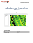
1
 SOFTWARE MANUAL
STRETCHOUTTM
(for use with Gatewing X100 UAS) Version 1.2
Publication Date: 9 October 2012
© 2011 Gatewing.
Gatewing® is a registered trademark of Gatewing NV.
Stretchout™ and X100™ are trademarks of Gatewing NV.
All other registered trademarks, trademarks and names of products and companies used in this
document belong to their respective owners.
All Rights Reserved. No part of this document may be photocopied, reproduced, stored in a
retrieval system, or transmitted, in any form or by any means, whether electronic, mechanical, or
otherwise, in whole or in part, without the prior written permission of Gatewing.
Gatewing NV
Ottergemsesteenweg 439 / 11
9000 Gent, Belgium
www.gatewing.com
Tel: +32 9 335 05 15
Fax +32 9 335 88 03
Mail: [email protected]
2
Software Manual: Stretchout
Version 1.2
TABLE OF CONTENTS
SYMBOLS USED IN THIS MANUAL
1. INTRODUCTION TO STRETCHOUT
2. DOWNLOADING STRETCHOUT
2.1 System Requirements
3. INSTALLING STRETCHOUT
3.1 Stretchout
3.2 Licensing Stretchout
4. MANAGING PROJECTS IN STRETCHOUT
4.1 Opening Screen Toolbar: Overview
4.2 Opening Screen Toolbar: Using the Buttons
4.2.1 Add Flight
4.2.2 Remove Flight
4.2.3 Flight Path
4.2.4 Stretchout and Cloud Processing
4.2.5 Export
5. PROCESSING WORKFLOW IN STRETCHOUT
5.1 Navigating the Processing Screen
5.2 Processing Screen Toolbar: Overview
5.3 Ground Control
5.3.1 Importing Ground Control Points (GCPs)
5.3.2 Setting the Coordinate System
5.3.3 Insert Ground Control Points Module
5.3.4 Navigating the Insert Ground Control Points Module
5.3.5 Editing Ground Control
5.4 Image Processing
5.4.1 Local Processing
5.4.2 Pix4D Cloud Processing
5.5 Managing Multiple Flights
6. FEEDBACK / CONTACT GATEWING
3
Software Manual: Stretchout
Version 1.2
SYMBOLS USED IN THIS MANUAL
A caution message indicates an important reminder about correct procedures and
practices in the operation of your software. Ignoring these reminders may result in
incorrect results without leading to actual error messages. A hint message indicates helpful hints or shortcuts. A reference message directs you to an internal reference within the document, a related
document or a web link. 4
Software Manual: Stretchout
Version 1.2
1. INTRODUCTION TO STRETCHOUT
Welcome to the Gatewing image processing software known as Stretchout, to be
used in conjunction with the Gatewing X100 aerial mapping and surveying
system.
The Gatewing X100 unmanned aircraft system (UAS) flies automatically along a
pre-programmed path, taking pictures at a specified altitude, along parallel lines
and with specified overlap between the image exposures. At the same time,
position information of the pictures is recorded for further processing. This image
acquisition is used to map terrain for orthophoto creation, digital terrain model
creation or photogrammetry.
But before you can use the images from the Gatewing X100 to generate an
orthophoto or digital elevation model (DEM), you must first have accurate
information about the orientation of the aircraft and its position when each image
was taken and the time at which each image was taken. Some of this information
is referred to as “geotags,” which identify each image uniquely with an exposure
station position. These data are recorded in a log file aboard the aircraft. The
process of associating each image with its exposure station position is referred to
as “synchronizing” or “geotagging” the images.
That’s where Stretchout comes in.
Stretchout synchronizes or geotags the images once the images and log file
information have been uploaded. Next, the images and exposure information can
be exported to a stand-alone image processing software package such as
AgiSoft PhotoScan Pro, Pix4UAV Gatewing Edition or EnsoMOSAIC. The
resulting data products from such image processing packages include
orthomosaics, DEMs and detailed reconstruction parameters in various formats
allowing 3D visualization in GIS software and compatible packages for potential
post-processing.
5
Software Manual: Stretchout
Version 1.2
2. DOWNLOADING STRETCHOUT
Contact your dealer or Gatewing support for obtaining the latest installer file of
Stretchout.
2.1 System Requirements Operating system minimum recommended Windows XP or later (64 bit) Windows XP or later (64 bit) CPU Any 64 bit processor Any 64 bit processor RAM 2 GB 4 GB Free hard disk space for processing 10 GB 10 GB 3. INSTALLING STRETCHOUT
3.1 Stretchout Stretchout is included free with each Gatewing X100 UAS System Kit and can
run “rapid” processing for a rough and quick result. While not a 100% guarantee
of good results, Stretchout can be used a bit like a proofing tool. However, it is
also possible that the provided rapid processing may not deliver a (complete)
result due to the type of land surface measured and the adverse effects of
working at a reduced resolution, although processing with a professional image
processing solution may produce a good result. However, many users may find
the orthomosaics from Stretchout to be adequate for their purposes (e.g. GIS
background layers).
3.2 Licensing Stretchout To install Stretchout properly, your computer must be connected to the Internet at
the time of starting your first processing session. This is so that verification of the
license can be done. Without this connection, Stretchout will not start the
processing window.
6
Software Manual: Stretchout
Version 1.2
Log-in credentials (username/password) are communicated by your dealer or
Gatewing. These credentials are valid for Stretchout.
If you are planning to use the program on a computer where the Internet will not
be accessible, be sure to run your first processing session in an environment
where the connection is feasible. Even if your computer is not connected to the
Internet later, Stretchout will run normally after a proper installation.
Users may install Stretchout on any computer.
7
Software Manual: Stretchout
Version 1.2
4. MANAGING PROJECTS IN STRETCHOUT
Stretchout allows you to manage the data (input and output) for each specific
flight that you do with the Gatewing X100. Each flight has associated with it a set
of imagery, data log files that are created by the plane while in flight and, if
applicable, a listing of ground control point coordinates.
To open Stretchout, double-click the Stretchout icon
the Windows Start menu.
on your Desktop or from
When you open Stretchout, you will see an opening screen that allows you to
manage your flights.
The flight list will show the project name, number of images, number of Ground
Control Points (GCPs), time and date of the first acquisition in a flight and
duration of the flight. Flights can be sorted according to any of the columns by
clicking the appropriate column header.
4.1 Opening Screen Toolbar: Overview The following actions are available in the toolbar on Stretchout’s opening screen:
8
Software Manual: Stretchout
Version 1.2
●
the
button allows you to add flights
●
the
button removes flights from the list
●
the
button allows you to see the complete flight path in 3D
●
the
button launches the Stretchout processing module
●
the
button allows you to export your flight information to other
processing software packages.
●
the
button allows you to upload your project to the Pix4D Cloud
If available, you may return to the primary toolbar by clicking
at any time.
4.2 Opening Screen Toolbar: Using the Buttons 4.2.1 Add flight
Clicking
on the toolbar allows you to indicate the location of the log files and
the images that need to be synchronized. The log files contain image acquisition
information, such as the position and orientation of the X100. These files can be
stored anywhere on your local, external or network drives, and log files from
different flights do not need to be stored together or in a common directory.
After you click,
use the LOG FILE button to indicate the location of the file of
the flight you want to add. The format of the log file is logyyyymmdd_hhmmss.txt.
Next, the FLY FILE button allows you to select the corresponding file. The format
of the fly file is logyyyymmdd_hhmmss.fly.
Finally, the IMG DIR button will prompt you to select the folder containing the
images. Click on the folder once to highlight it, and then choose SELECT.
The X100 system may take images while the aircraft is on the launcher.
Additionally, the operator may have taken test images before the flight. Be sure
these images are deleted from the set of images that are in the folder selected by
IMG DIR. Otherwise, the processing results will be erroneous and not likely to be
useful.
9
Software Manual: Stretchout
Version 1.2
The LOG FILE, FLY FILE and IMG DIR buttons will turn blue when a valid
location is set for them. After you have set the IMG DIR by clicking SELECT, you
will see a dialogue box summarizing the file names of the LOG and FLY files and
the number of images. The dialogue box will prompt you to enter a flight name
and confirm by clicking ADD. The flight will be added to the list with a
consecutive ID number.
For project names, use only alphanumeric characters. Do not use any
special characters including space, dash, underscore, etc. Project names are not
case sensitive.
Two flights can have exactly the same project name. Projects with the same
name are stored in the internal database based on the differing project ID
number, image count, duration and date and time of the flight.
Make sure to identify properly for yourself the corresponding files and
images of each flight, especially when you have multiple flights over the same
area. Mixing up flight files and images may go unnoticed at this stage but leads
to flaws in the image processing or to error messages stating that the data
cannot be processed. 4.2.2 Remove flight
Select a flight (a single click in the list will highlight the flight in blue) and click
to remove the flight from the list.
You will be asked for confirmation to remove a flight. 10
Software Manual: Stretchout
Version 1.2
Removing a flight from the list will not remove the flight and image files from your
disk.
4.2.3 Flight path
To create a representation of the flight path for a selected flight in the list, click
the
button. The corresponding KML file will be created in the folder
containing the log file. The logged GPS positions will be used to create a line of
flight from takeoff to landing.
A link to the KML file will be shown in the toolbar above the flight list. The link will
open the KML file using the default software assigned to KML files on your
system (typically Google Earth).
11
Software Manual: Stretchout
Version 1.2
4.2.4 Stretchout and Cloud Processing
Select a flight and click
a separate window.
or
to launch the Stretchout Processing Screen in
The processing module will be opened in a separate window. You can switch
back to the opening screen to manage your flights at any time, and by selecting
other flights you can open any number of parallel processing windows.
Note that if you begin local processing in several processing windows, this
usually means that each process will be processed sequentially, as you generally
will not have enough computing resources to have your processing run on
separate threads that are as fast as a single processing job.
How you initiate local or cloud processing and all functions you can access
in the processing module are covered in the “Processing Workflow” section of
this manual, Page 14.
If Ground Control Points (GCPs) are identified in the Stretchout Processing
Screen, they will be shown in the GCP column in the table view. 12
Software Manual: Stretchout
Version 1.2
4.2.5 Export
Select a flight and click the
button to bring up the options to export a flight for
processing in other compatible software packages.
Clicking AgiSoft PhotoScan1 will create a flightname.psz file and display a
link to the file in the toolbar.
Clicking Pix4UAV Gatewing Edition (formerly known as Stretchout Pro) creates a
flightname.p4d file and displays a link to the file in the toolbar.
The EnsoMosaic2 button creates both a flightname.trp and a
flightname.gps file. Also, a link to these files is displayed in the toolbar. A
warning message appears when the EnsoMOSAIC export is selected, reminding
users to enter the path to the calibration file of the camera used for this particular
flight in the corresponding field of the created TRP file, which can be done in any
text editor.
Clicking Generic will create a flightname.csv file and display a link to the file in
the toolbar. This file contains the image positions (GPS X,Y,Z) and orientations
(UAV roll, pitch, yaw) as recorded in the aircraft log file.
All export files are by default created in the same folder as the LOG file.
Please refer to the user manual of the software packages supported in the Export
function for information on how to use the exported files. 1
PhotoScan is a product of AgiSoft LLC (http://www.agisoft.ru/products/photoscan/professional/). 2
EnsoMOSAIC is a product of MosaicMill Oy (http://www.ensomosaic.com/) 13
Software Manual: Stretchout
Version 1.2
5. PROCESSING WORKFLOW IN STRETCHOUT
5.1 Navigating the processing screen Projects can be processed through local desktop processing and/or through
Pix4D cloud processing.
Click
on the opening screen to open the Stretchout processing window. The
window layout is presented in the figure below.
In the main panel, the image acquisition positions are displayed as blue dots on a
selectable background of either a grid, map or satellite view. When you hover the
mouse over the main panel, the coordinates are displayed in the lower right
corner.
Putting the mouse arrow on an image position will display the image name next
to the coordinate display. View the corresponding image by double clicking the
blue dot.
The Project Summary panel gives an overview of the project size, GCPs and
coordinate system, along with processing status and statistics. The display of
image acquisition centers, potential GCPs and polygons drawn to select
processing areas (see further) can be toggled in the Layers panel.
14
Software Manual: Stretchout
Version 1.2
5.2 Processing Screen Toolbar: Overview The following actions are available in the toolbar on Stretchout’s processing
screen:
● Click
in the Stretchout Processing Window to open the project menu
from which the user can save projects, add projects, change the
coordinate system and toggle the summary view.
● The
button allows you to run the image processing on your local
machine.
● The
button allows you to upload your project to the Pix4D Cloud.
● Click the
button to include your Ground Control Points.
● Click the
button to modify your Ground Control Points.
●
The
button shows you the processing quality report.
●
The
button shows you the build-in help content.
●
The
button allows you to select a background image.
5.3 Ground Control 5.3.1 Importing Ground Control Points (GCPs)
To improve the accuracy of your mapping and DEMs, you can use ground control
points that are well distributed across the area and elevation ranges of the
project to fix the solved photogrammetric model within the accuracy of your
ground control system. Generally, accuracy of the positioning of ground control
must be one-half to three times the ground sampling distance or GSD (the
distance represented by a single pixel). Typically, in a flight that is operated at
150 m above ground level (AGL), GSD will be 5 cm. Thus, to be meaningful,
ground control must have an absolute accuracy in the range of 2.5 to 15 cm.
Remember that the referencing of the data products will be limited by the
accuracy inherent in the internal consistency of the ground control coordinates
you input.
Ground control points are any photo-identifiable points for which you have
coordinates in a single system (datum and projection). These points must be
clearly visible in the photographs. Many times, markings are placed on the
ground before flight to ensure that the points are visible, but more permanently
visible structures such as corners of road marks and artificial constructions can
15
Software Manual: Stretchout
Version 1.2
also be used. The general recommendations for custom-made ground control
point markers include a unique appearance with an unambiguous point of
measurement on the images, a non-reflective color contrasting with the
substrate, a size of at least five times the image pixel size, and ease of use in the
field.
When ground control points are available, these should be entered first, before
beginning processing. If you have already processed the imagery, you can enter
the ground control information and reprocess the data for higher quality
positioning, consistent with the accuracy of your ground control.
Enter GCP names and coordinates using the ADD GCP
toolbar.
button on the
A dialogue box appears when you click the
button from which you can import
ground control points in a list (created in a spreadsheet program or text editor) by
clicking the “from .csv” button.
Next to the “from .csv” button, there is a direct link to the GCP file format
topic in the help file.
The names (identifiers) and coordinates of the respective ground control points
can be imported either as space, tab or comma separated TXT or CSV files; both
forms are accepted. Ground control points listed in TXT or CSV files should not
contain any headers. Records are listed each on a separate line in the following
order: identifier,latitude[decimal degrees],longitude[decimal
degrees],height[meter] for GCPs measured in WGS84 lat/long degrees or
identifier,x[meter],y[meter],z[meter] for GCPs measured in any
projected coordinate system, where x denotes the west-to-east position and y
refers to the south-to-north position. Note that lat/long coordinates should be
formatted as decimal degrees, with negative entries for western and southern
hemispheres. When using a spreadsheet as GCP editor, please make sure your
system country settings are set to use a point as decimal separator (instead of a
comma).
16
Software Manual: Stretchout
Version 1.2
5.3.2 Setting the Coordinate System
After the GCP file has been selected, you can use one of three options to set the
coordinate system (datum and projection zone) in which the ground control
points are measured. Click the “from list” button to access drop-down lists from
which you can select the respective datum and coordinate system (projection).
Alternatively, you can set the datum and corresponding coordinate system by
indicating the unique EPSG code (see www.epsg.org).
If the desired coordinate system is not available in the drop-down lists, you can
add a coordinate system by uploading a PRJ file in well-known text format using
the “from .prj” button. However, only PRJ files containing the seven TOWGS84
(also called Helmert) parameters can be used.
The status panel below the coordinate system selection buttons displays the
GCP file name, datum and coordinate system. When you click OK, the insert
ground control points module opens automatically if the coordinates of the
ground control points match the project coordinates reasonably well.
In case of mismatches — for example, if the x and y fields have been changed in
the GCP text file, or if a wrong coordinate system was selected — the “insert
ground control points module” will not open, and the following error message will
be displayed in the status panel:
17
Software Manual: Stretchout
Version 1.2
The datum and coordinate system in which the GCPs are added in the
project and set in this dialogue box will determine the datum and coordinate
system of the output files. Hence, for projects without ground control, the default
output coordinate system is WGS84 UTM, while the output files of projects with
ground control will be georeferenced in the datum and coordinate system of the
GCPs by default.
5.3.3 Insert Ground Control Points Module
In the main panel of the processing window, the positions of the ground control
points, as determined from the coordinates you have entered, will be indicated at
first by red crosses.
If possible, check the positions of the ground control points in the main
panel of the processing window thoroughly. Selecting a wrong coordinate system
may not lead to the error message described above if such an error causes only
a minor shift.
Hovering the mouse over a cross will display the GCP identifier next to the
coordinate display in the lower right corner. The following warning will appear in
the project summary panel:
18
Software Manual: Stretchout
Version 1.2
For a project to be processed with GCPs, ground marker positions should be
indicated on the images for at least three GCPs. When enough GCPs have been
indicated in the corresponding images, the warning message in the project
summary panel on the processing window disappears.
Although a project can theoretically be processed with as little as three
(without error estimates) or four GCPs (allowing error estimates), it is strongly
advisable to add as many GCPs per project as possible, with five as a practical
minimum and more for larger projects (consisting of multiple flights). Even more
importantly, GCPs should be well spread out across the terrain towards the
edges but also in the center, in x, y and z. Ideally, marker positions should only
be indicated on images where the measurement point can be determined at the
pixel level.
For each GCP to be included, the corresponding positions should be indicated on
at least two images. When this is done, the label “Not enough image points”
disappears from the GCP identifier list, and the cross in the main panel of the
processing window turns green.
19
Software Manual: Stretchout
Version 1.2
GCP ground marker positions should ideally be indicated on as many
images as possible, provided they are not blurred. Indicating the GCP on images
where the ground marker(s) are blurry may introduce small errors.
5.3.4 Navigating the Insert Ground Control Points Module
The insert ground control points module consists of three panels:
● The left panel shows the ground control point identifiers in alphabetical
order.
● The middle panel shows the list of images in the project.
● The right panel shows the selected image on which a ground control point
may be indicated by clicking on the ground markings visible in the image.
20
Software Manual: Stretchout
Version 1.2
To remove an inserted ground control point from an image, right click on the
image name in the list and choose DELETE CLICKED GCP.
To remove a GCP from the project, including all of its ground marker positions
indicated on all the images, right click on the identifier in the left panel list and
choose DELETE.
Zoom in and out on the displayed photo by using the mouse scroll wheel or a
touch pad.
By default, the items in the image list are sorted according to position, with
the closest position to the respective GCP identifier displayed first in the list. The
closest position is calculated based on comparison of the GPS-recorded image
position and the coordinates in the GCP text file.
You can also sort the image list alphabetically by right-clicking in the image list
and choosing SORT IMAGES BY>.
Pan by holding the right mouse button while dragging.
You can insert a ground control point into a photo with a single click of the
left mouse button; simply clicking again anywhere in the photo will move the
ground control point to the new pixel that was clicked.
5.3.5 Editing Ground Control
21
Software Manual: Stretchout
Version 1.2
Ground control can be edited after initial entry. Users may find that they have to
add or delete ground control points or need to select the ground control marker
location(s) more accurately. This can be performed by clicking on the edit ground
control button
window.
or by double-clicking on a ground control point in the main
By clicking “save project” in the
project menu, the number of actually
indicated GCPs (which may differ from the total number of GCPs in the added
file) will be added to the database in the Stretchout opening screen (visible after
closing and re-opening the opening screen). When generating a PhotoScan .psz
file from the
export list, the identifiers and the location of these GCPs on the
images will also be stored in the generated project file.
5.4 Image Processing In the processing screen, you can optionally import ground control points and
indicate ground marker positions. You can then choose to process your flight
locally using the
using the
button or submit it to the Pix4D cloud server for processing
button.
5.4.1 Local Processing
Click the local processing button
to start the processing on your machine.
This will add the following pane to the bottom of the processing window:
The desired steps can be selected, before clicking the Start button. You have the
choice to carry out the steps one by one or by selecting all the steps at once.
When launching the local processing from Stretchout, no changes can be
made to the processing parameters (i.e., rapid initial processing, four times
reduced resolution) and step 2 (dense matching) is not available.
22
Software Manual: Stretchout
Version 1.2
Step 1: In the “Initial project processing” section at the bottom, rapid processing
is done at one-fourth of the original image resolution, possibly leading to
incomplete results, while dramatically increasing processing speed. When step 1
is completed, the Automatic Reconstruction Report shows up in a pane at the
right side of the processing window or can be consulted by clicking the report
button
. The report can also be consulted in PDF format by clicking the PDF
link in the report pane (the PDF file can be found in the results folder of the
project, which is automatically generated in ../projectname/results in the
directory where the project log file resides).
Step 3: In the “Generate Orthomosaic” section, the resolution is fixed at four
times the native image resolution.
The area for which end products will be generated can be set by clicking Draw
under Orthomosaic area in the Project menu. Any polygon can be drawn by left
clicking in the map pane to insert a vertex and right clicking to close the
orthomosaic area. The orthomosaic area should be drawn before starting step 3.
The area display can be toggled in the layers pane. The Stretchout processing
generates the orthomosaic in GeoTIFF format, available in the
../projectname/results folder. This folder is automatically generated by
Stretchout in the same directory where your X100 logfile resides.
5.4.2 Pix4D Cloud Processing
Click the cloud processing button
to upload your project. Fill in your username
and password and click the "upload" button to start transferring your images to
our cloud server. The username and password combination is exactly the same
as the one used for registering the software (see “Licensing Stretchout”, p. 7).
You can monitor the processing status at our cloud page:
http://gatewing.pix4d.com
More information on Gatewing cloud processing is explained here:
http://gatewing.pix4d.com/faq
23
Software Manual: Stretchout
Version 1.2
You can always stop the upload by closing down the Cloud Processing window.
It is possible to resume the upload at any time.
When you are using the cloud, an e-mail is sent to you as soon as the initial
processing is over. The corresponding Automatic Reconstruction Report can
then be downloaded as a PDF file.
You should thoroughly review the report generated at initial processing before
making the decision to move forward with the purchase of your desired products,
Ortho or Full:
● Ortho contains a basic orthomosaic;
● Full creates orthomosaic (GeoTIFF, KML tiles), DEM (GeoTIFF, XYZ),
internal and external orientation parameters and several export formats.
24
Software Manual: Stretchout
Version 1.2
5.5 Managing Multiple Flights Combining several adjacent flights for processing as one block can be done in
the following way:
Step 1: Add your flights individually to the list in the Stretchout opening screen by
indicating the respective files and folders and naming them appropriately.
Make sure there are no flights with identical image file names (this may
occur if you have for instance acquired some of the flights you want to merge
with several cameras). If so, batch rename the files but avoid brackets or spaces
or any other special characters.
Step 2: For each flight, click the processing button
to open the Stretchout
processing window. You don't have to do anything further here, just click close
again and choose "save". This creates a Stretchout project .p4d file in the same
folder as the log file for the respective flight.
Step 3: Select one of the flights and click the processing button
again to start
adding other flight projects; as the main window shows up, go to the project
menu button
in the toolbar and click "add project". From there on, browse to
the .p4d files for the other flights you want to add - repeat this for each flight. You
will see the added photos show up in the main window allowing you to check if
the projects are contiguous and complete (and see if the ground control points
are covered by the flights, if you have ground control points available)
If you have ground control points, you do not need to add these for each
separate flight before adding projects. You can simply merge your projects first
using the process described above, and then add your ground control points for
the whole contiguous block at once to save time.
Step 4: Go to the processing menu
again and choose "save as..." to rename
your project to the whole contiguous block. When you click upload to the cloud
or process locally
processed as one. 25
Software Manual: Stretchout
Version 1.2
next, the whole project with multiple flights will be
6. FEEDBACK / CONTACT GATEWING
Gatewing encourages your comments concerning this manual or software. We
are committed to providing documentation and software that meet your needs.
Please send any comments by contacting us at [email protected].
Please include the name of the document/software and any comments, errors
found or suggestions you have for improving this manual or the software’s
operation.
Contact Gatewing customer support:
Tel: +32(0)2/669 66 69
E-mail: [email protected]
26
Software Manual: Stretchout
Version 1.2