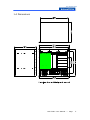
1
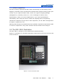
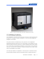
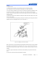
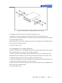
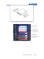
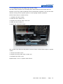
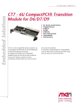
MIC-3081
10U high 8-slot
enclosure with CT bus
and rear I/O for
CompactPCI™ backplane
Advantech CompactPCI™
Modular Industrial Computer
Copyright Notice
This document is copyrighted, 2003. All rights are reserved. The original
manufacturer reserves the right to make improvements to the products described in
this manual at any time without notice. No part of this manual may be reproduced,
copied, translated or transmitted in any form or by any means without the prior
written permission of the original manufacturer. Information provided in this
manual is intended to be accurate and reliable. However, the original manufacturer
assumes no responsibility for its use, nor for any infringements upon the rights of
third parties which may result from its use.
Acknowledgements
PICMG™ , CompactPCI™ and the PICMG™ , CompactPCI™ logos are trademarks of
the PCI Industrial Computers Manufacturers Group. All other product names or
trademarks are properties of their respective owners.
CE Notification
The MIC-3081, developed by Advantech Co., Ltd., has passed the CE test for
environment specifications when shielded cables are used for external wiring. We
recommend the use of shielded cables.
Part No. 2008308100
1st Edition
Printed in Taiwan
Apr 2003
MIC-3081 User Manual --- Page
II
Product warranty
Advantech warrants to you, the original purchaser, that each of its products will be
free from defects in materials and workmanship for one year from the date of
purchase.
This warranty does not apply to any products which have been repaired or altered
by persons other than repair personnel authorized by Advantech, or which have
been subject to misuse, abuse, accident or improper installation. Advantech
assumes no liability under the terms of this warranty as a consequence of such
events.
Because of Advantech’s high quality-control standards and rigorous testing, most of
our customers never need to use our repair service. If an Advantech product is
defective, it will be repaired or replaced at no charge during the warranty period. For
out-of-warranty repairs, you will be billed according to the cost of replacement
materials, service time and freight. Please consult your dealer for more details.
If you think you have a defective product, follow these steps:
1. Collect all the information about the problem encountered. For example, CPU
speed, Advantech products used, other hardware and software used, etc. Note
anything abnormal and list any on-screen messages you get when the problem
occurs.
2. Call your dealer and describe the problem. Please have your manual, product,
and any helpful information readily available.
3. If your product is diagnosed as defective, obtain an RMA (return merchandise
authorization) number from your dealer. This allows us to process your return more
quickly.
4. Carefully pack the defective product, a fully-completed Repair and Replacement
Order Card and a photocopy proof of purchase date (such as your sales receipt) in
a shippable container. A product returned without proof of the purchase date is not
eligible for warranty service.
5. Write the RMA number visibly on the outside of the package and ship it prepaid to
your dealer.
MIC-3081 User Manual --- Page
III
Packing List
Before installation, ensure that the following materials have been received:
• One MIC-3081 CompactPCI™ enclosure with backplane
• One box of accessories
• One warranty certificate
• One CD-ROM for user’s manual (PDF file)
• One quick startup guide
If any of these items are missing or damaged, contact your distributor or sales
representative immediately.
Technical Support and Sales Assistance
If you have any technical questions about the MIC-3081 or any other Advantech
products, please visit our support website at:
• http://www.advantech.com.tw/support
For more information about Advantech's products and sales information, please
visit:
• http://www.advantech.com.
MIC-3081 User Manual --- Page
IV
Contents
1. General Information...................................................................... 1
1.1 Introduction ................................................................................. 2
1.2 Features........................................................................................ 3
1.3 Specifications ................................................................................ 4
1.3.1 General .......................................................................................... 4
1.3.2 Hot-swap Fans ................................................................................ 4
1.3.3 Power Supply .................................................................................. 5
1.4 Dimensions ............................................................................ 6
2. Installation ................................................................................. 7
2.1 Initial Inspection ........................................................................... 8
2.2 The MIC-3081/8 Illustration ............................................................ 9
2.3 Installation Procedures .................................................................. 11
2.3.1 Card Installation and Removal .......................................................... 11
2.3.2 Before Operating the System ........................................................... 13
2.3.3 Installing Peripherals ...................................................................... 13
2.3.4 Installing a 5.25" Device ................................................................. 14
2.3.5 Installing a 3.5" Floppy Disk Drive ................................................... 15
2.3.6 Replacing the Hot-swap Fan and Air Filter ......................................... 16
Figures
Figure 1-1: MIC-3032/8 dimensions ......................................................................... 6
Figure 2-1: Front view of MIC-3081/8 ...................................................................... 9
Figure 2 -2: Rear view of MIC-3081/8 ...................................................................... 10
Figure 2 -3: Installing a card into the chassis ............................................................ 12
Figure 2-4: Attaching the mounting brackets to a 5.25" device .................................... 14
Figure 2 -5: Attaching the mounting brackets to a 3.5" floppy disk drive ....................... 15
Figure 2 -6: Recommended device bay configuration .................................................. 16
MIC-3081 User Manual --- Page
V
MIC-3081 User Manual --- Page
VI
1
General Information
MIC-3081 User Manual --- Page
1
1.1 Introduction
The MIC-3081 series CompactPCI is a 10U-high enclosure with eight CompactPCI
slots for rack mounting, which is provided as a flexible, configurable development
platform. It supports 8-slot backplane H.110 CT bus backplane and rear I/O, which
is designed to speed the implementation of telecom Internet and Industrial
automation applications.
Optimal for cooling airflow with hot-swap fans
A 2.5U space underneath the card slots accommodates two 163 CFM high-speed
fans, to provide forced cooling air into the system. There are also two high-speed
blowers on the top (1.5U space) for linear air flow to optimal the chassis cooling
system. All the fans in this chassis are individually hot-swappable, allowing users to
replace any of the fans without interrupting the operation of the system. The fan’s
tachometer output enables the alarm module to monitor the speed of the fans. A
protective circuit has been designed into the fan backplane to reduce spikes and
noise during fan hot-swapping. This design allows users to replace new fans safely
without turning the system off.
System fault detection and alarm notification
The MIC-3081A is integrated with a system fault-detection and alarm notification
(MIC-3921). Versatile power supply options and configurations can be made
according to particular application requirements. The MIC-3081B can optional with
an intelligent chassis management module, the MIC-3924A, to monitor and report
internal conditions via SNMP trap, email, pager and beep sounds. The system’s
status including CPU (SBC) temperature, system power voltage levels, and fan
speeds can be easily checked from remote web browser for administrator
monitoring. The chassis management module’s serial port can be linked to a modem,
to communicate to a remote host for real time monitoring, module configuration
and alarm reporting. No software needed for remote monitoring since the
SNMP/HTTP protocol provide an open platform for all the operating system.
Hot-swap passive backplane with H.110 CT-bus
The 6U-sized 8-slot backplane of the MIC-3081 supports 32/64-bit operation, the
backplane complies with PICMG 2.1 hot-swap specification. Eight CompactPCI slots
are available. Slot 8 is dedicated to the system master, while slot 1 through 7are
available for 32/64-bit CompactPCI peripheral boards. Connectors P3 and P5 on
each peripheral slot of the telephony backplane are configured for rear I/O, while
connector P4 is configured for the ECTF H.110 CT-bus (TDM telephony bus). The
MIC-3081 User Manual --- Page
2
backplane may be configured for +3.3V or +5V V(I/O) CompactPCI device support.
A short-bar is provided on the backplane to select the desired V(I/O) voltage. The
eight rear I/O are provided directly behind the backplane for IEEE1101.11
specification, 80mm depth transition board. Slot 8 is dedicated to the system
master, and slot #1 through #7 are available for additional rear I/O boards.
10U-High CompactPCI™ Enclosure with 8-slot Backplane
There are two MIC-3081 models:
• MIC -3081A/8-4R: MIC-3081 clone system, w/ 8-slot CompactPCI™ 6U
backplane (MIB-3021CT), advance intelligent alarm module (MIC-3921)
• MIC -3081B/8-4R: MIC-3081 clone system, w/ 8-slot CompactPCI™ 6U
backplane (MIB-3081A), chassis management module (MIC-3924A)
1.2 Features
•
10U-high enclosure, 19-inch enclosure
•
8-slots 6U CompactPCI backplane
•
Supports rear I/O
•
H. 110 CT bus compliant (PICMG 2.5)
•
460W single ATX or 560 W N+1 redundant ATX power supply
•
Hot swappable fan modules and blowers
•
Advance intelligent alarm module / chassis management module as option
•
Device bay accommodates up to three devices
1.3 Specifications
1.3.1 General
• 6U Slot: 6U CompactPCI x 8, transition x 8 (80mm, IEEE1101.11 compatible)
• Bus : 32-bit/33MHz, 64-bit/66MHz
• VI/O Voltage: 3.3 V/5 V (short-bar selectable)
• Fan: 2 (163 CFM/each, 15 cm) on the chassis bottom (Inlet)
• Blowers : 2 (40 CFM/each, 12 cm) on the chassis top (Outlet)
• Power Requirement Input: AC 100-240V @ 47-63 Hz, full range
• Safety: CE, TUV, CUL, UL
• Dimensions (W x H x D, mounting flanges not included): 444 x 446 x 342 mm
(17.48” x 17.56” x 13.46”)
• Weight: 18 kg (39.65 lb)
• Serviceability MTTR: 5 minutes
• Standard: PICMG 2.0, R3.0 CompactPCI specifications
MIC-3081 User Manual --- Page
3
PICMG 2.1, R2.0 CompactPCI Hot-Swap specifications
PICMG 2.5, R1.0 CompactPCI Computer Telephony specification
1.3.2 MIC-3081A/8-10R 560W N+1 redundant ATX MIC -3921 &
MIC-3081B/8-10R 560W N+1 redundant ATX MIC -3924A
• Output: 560 W (N+1 redundant) ATX*
• Max. Load: +3.3 V @ 36 A*, +5 V @ 58 A*, -5 V @ 0.5 A, +12 V @ 20 A
-12 V @ 1.5 A, +5 V @ 1.5 A
• Min. Load: +3.3 V @ 0.3 A*, +5 V @ 2.0 A*, -5 V @ 0.0 A, +12 V @ 0.5 A
-12 V @ 0.0 A, +5 V @ 0.1 A
• Temperature: 0-50ºC, (32-122ºF)
• Shock: 10 G
• Vibration (5-500 Hz): 1.0 Grms
1.3.3 MIC-3081A/8-10A 460W single ATX MIC -3921
• Output: 460 W (N+1 redundant) ATX*
• Max. Load: +3.3 V @ 45 A**, +5 V @ 40A*, -5 V @ 0.0 A, +12 V @ 16 A
-12 V @ 1.5 A, +5 V @ 1.5 A
• Min. Load: +3.3 V @ 0.3 A*, +5 V @ 2.0 A*, -5 V @ 0.0 A, +12 V @ 0.5 A
-12 V @ 2.0 A, +5 V @ 3.5 A
• Temperature: -20 ~ 80 ºC, (-4 ~ 176 ºF)
• Humidity: 10-95% @ 40ºC non-condensing
• Shock: 30 G
• Vibration (5-500 Hz): 2.0 Grms
MIC-3081 User Manual --- Page
4
1.4 Dimensions
MIC-3081 User Manual --- Page
5
2
Installation
MIC-3081 User Manual --- Page
6
2.1 Initial Inspection
We have carefully inspected the MIC-3081 mechanically and electrically before
shipping. It should be free of marks and scratches and in perfect working order upon
receipt. As you unpack the MIC-3081, check it for signs of shipping damage
(damaged box, scratches, dents, etc.). If it is damaged or fails to meet
specifications, notify our service department or your local representative
immediately. Also notify the carrier. Retain the shipping carton and packing
material for inspection by the carrier. After inspection, we will make arrangements
to repair or replace the unit.
Warning! We strongly recommend that only qualified, experienced personnel install
or remove components. They must exercise extreme caution when doing so.
2.2 The MIC-3081 Illustration
The MIC-3081 is designed to be installed and maintained easily.
Figure 2-1 and Figure 2-2 illustrate important components on the front and rear side
of the enclosure.
Figure 2-1: Front view of MIC-3081
MIC-3081 User Manual --- Page
7
Figure 2-2: Rear view of MIC-3081A (with advance intelligent alarm module)
2.3 Installation Procedures
2.3.1 Card Installation and Removal
The CompactPCI™ connectors are firm and rigid, and require careful handling while
plugging and unplugging. Improper installation of a card can easily damage the
backplane of the chassis.
The system card can be installed only in the system slot. The CompactPCI™
specification allows the system slot to be in any position in the backplane. Do not
insert the system card into any other slot, or insert a peripheral card into the system
slot. The MIC-3081 accepts different backplanes, so the location of the system slot
may vary. The system slot is marked by a triangle enclosing the slot number. Please
refer to the backplane user's manual.
The insert/eject handles on CompactPCI™ cards help users to install and remove
the cards easily and safely. Follow the procedures below to install a card into a
MIC-3081 User Manual --- Page
8
chassis:
To install a card:
1. Hold the card vertically. Be sure that the card is oriented correctly.
The components of the card should be pointing to the right-hand side.
2. Be sure that the handles of the card are not latched. Release the handles if they
are latched. Handles from different vendors may have different latch designs.
Caution: Keep your fingers away from the latch hinges to prevent your fingers from
getting pinched.
3. Insert the card into the chassis by sliding the upper and lower edges of the card
into the card guides.
4. Push the card into the slot gently by sliding the card along the card guide until the
handles meet the rectangular holes of the cross rails. 1 2
Figure 2-3: Installing a card into the chassis
Note: If the card is correctly positioned and has been slid all the way into the chassis,
the handles should match the rectangular holes. If not, remove the card from the
card guide and repeat step 3 again. Do not try to install a card by forcing it into the
chassis.
5. Pull the upper handle down and lift the lower handle up to push the card into
place.
6. Secure the card by locking the handles into place.
MIC-3081 User Manual --- Page
9
To remove a card:
1. Unscrew the screws on the card front panel. Release the locking latches on the
handles.
2. Lift the upper handle up and press the lower handle down to release the card from
the backplane.
3. Slide the card out.
2.3.2 Before Operating the System
Before operating your system, first check your power supply source. Adjust the
switch on the power supply to the correct voltage. Two mounting flanges are
included for users who would like to install the MIC-3081 on a 19" rack or on a panel.
These flanges can be installed on the front side for rack mounting or on the rear side
for panel mounting. Four rubber stands can be attached to the bottom of the chassis
for desktop operation. They are not required for rack mounting.
2.3.3 Installing Peripherals
The device bay of the MIC-3081 accepts three devices, include two 5.25"/3.5"
devices and one 3.5" floppy disk drive. There are two types of mounting brackets
shipped with the MIC-3081. Three pairs of mounting brackets are designed for
mounting 5.25" devices such as hard disk drives or CD-ROM drives. Please refer to
Figure 2-4 for an illustration of mounting. However, if users would like to use a 3.5"
hard disk drive in the MIC-3081, extension brackets (3.5" to 5.25") are required.
These extension brackets are commonly available in PC shops, or users can contact
an Advantech distributor to order them. For mounting a 3.5" floppy disk drive, a pair
of mounting brackets is provided. Users can mount the floppy disk drive on the top
tray in the device bay. Please refer to Figure 2-5 for an illustration of mounting.
Figure 2-6 shows the recommended device bay configuration.
2.3.4 Installing a 5.25" Device
Follow the procedures below to install a 5.25"/3.5" device:
1. Fasten one pair of mounting brackets to both sides of a 5.25" device (or a 3.5"
device with extension brackets). Note that the guide edges of the mounting
brackets should be on the lower side.
MIC-3081 User Manual --- Page
10
Figure 2-4: Attaching the mounting brackets to a 5.25" device
2. Unfasten and remove the cover plate of the device tray.
3. Insert the device with attached mounting brackets into the device tray.
4. Fasten the mounting brackets to the device bay, and then fasten the cover plate
(for internal devices only).
5. Open the back cover of the chassis, and connect the cables to the installed device
and to the rear transition board.
6. Close the back cover.
2.3.5 Installing a 3.5" Floppy Disk Drive
A space is reserved for a 3.5" floppy disk drive on the top of the device bay. Follow
the procedures below to install a 3.5" floppy disk drive.
1. Fasten one pair of mounting brackets to both sides of a 3.5" floppy disk drive.
Note that the guide edges of the mounting brackets should be on the lower side.
2. Unfasten and remove the top cover plate of the device tray.
3. Insert the floppy disk drive with attached mounting brackets into the device tray.
4. Fasten the mounting brackets to the device bay.
5. Open the back cover of the chassis, and connect the cables to the installed device
and to the rear transition board.
6. Close the back cover.
MIC-3081 User Manual --- Page
11
Figure 2-5: Attaching the mounting brackets to a 3.5" floppy disk drive
1x 3.5” FDD
drive bay
Up to 3x 3.5”
5.25 drive bays
(w/single ATX)
Redundant
560W P/S or 460
single ATX
Figure 2-5: Recommended device bay configuration
MIC-3081 User Manual --- Page
12
2.3.6 Replacing the Hot-swap Fan and Air Filter
The MIC-3081 provides two hot-swap fans underneath the card slots and two
blowers on the top. Each fan/blower can be individually replaced. This can be done
without turning off the system power or interrupting system operation.
Follow these steps to replace a fan:
1. Unfasten the fan's holder.
2. Slide the fan's holder out.
3. Replace the old fan with a new one.
4. Slide the fan's holder in.
5. Fasten the new fan's holder.
The air filter may become dirty after a period of time. Follow these steps to replace
a filter:
1. Remove the filter cover.
2. Replace the dirty filter with a clean one.
3. Reattach the filter cover.
Repeat steps 1 to 3 to replace other filters.
MIC-3081 User Manual --- Page
13