1
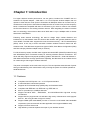
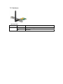
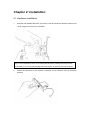
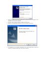
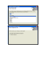
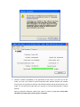
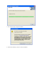
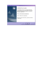
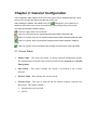
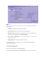
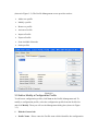
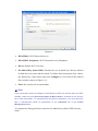
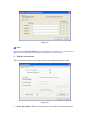
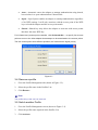
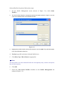
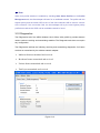
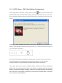
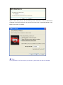
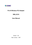
802.11n Wireless PCI Express Adapter
WNL-9501
User’s Manual
Version: 1.00
Date: August 2010
Copyright
Copyright
© 2010 by PLANET Technology Corp. All rights reserved. No part of this
publication may be reproduced, transmitted, transcribed, stored in a retrieval system, or
translated into any language or computer language, in any form or by any means, electronic,
mechanical, magnetic, optical, chemical, manual or otherwise, without the prior written
permission of PLANET.
PLANET makes no representations or warranties, either expressed or implied, with respect to
the contents hereof and specifically disclaims any warranties, merchantability or fitness for any
particular purpose. Any software described in this manual is sold or licensed "as is". Should
the programs prove defective following their purchase, the buyer (and not PLANET, its
distributor, or its dealer) assumes the entire cost of all necessary servicing, repair, and any
incidental or consequential damages resulting from any defect in the software. Further,
PLANET reserves the right to revise this publication and to make changes from time to time in
the contents hereof without obligation to notify any person of such revision or changes.
All brand and product names mentioned in this manual are trademarks and/or registered
trademarks of their respective holders.
Federal Communication Commission Interference Statement
This equipment has been tested and found to comply with the limits for a Class B digital device,
pursuant to Part 15 of FCC Rules. These limits are designed to provide reasonable protection
against harmful interference in a residential installation. This equipment generates, uses, and
can radiate radio frequency energy and, if not installed and used in accordance with the
instructions, may cause harmful interference to radio communications. However, there is no
guarantee that interference will not occur in a particular installation. If this equipment does
cause harmful interference to radio or television reception, which can be determined by turning
the equipment off and on, the user is encouraged to try to correct the interference by one or
more of the following measures:
1. Reorient or relocate the receiving antenna.
2. Increase the separation between the equipment and receiver.
3. Connect the equipment into an outlet on a circuit different from that to which the
receiver is connected.
4. Consult the dealer or an experienced radio technician for help.
FCC Caution
To assure continued compliance. (example-use only shielded interface cables when
connecting to computer or peripheral devices). Any changes or modifications not expressly
approved by the party responsible for compliance could void the user’s authority to operate the
equipment.
This device complies with Part 15 of the FCC Rules. Operation is subject to the Following two
conditions: ( 1 ) This device may not cause harmful interference, and ( 2 ) this Device must
accept any interference received, including interference that may cause undesired operation.
Federal Communication Commission (FCC) Radiation
Exposure Statement
This equipment complies with FCC radiation exposure set forth for an uncontrolled
environment. In order to avoid the possibility of exceeding the FCC radio frequency exposure
limits, human proximity to the antenna shall not be less than 20 cm (8 inches) during normal
operation.
R&TTE Compliance Statement
This equipment complies with all the requirements of DIRECTIVE 1999/5/CE OF THE
EUROPEAN PARLIAMENT AND THE COUNCIL OF 9 March 1999 on radio equipment and
telecommunication terminal Equipment and the mutual recognition of their conformity (R&TTE).
The R&TTE Directive repeals and replaces in the directive 98/13/EEC (Telecommunications
Terminal Equipment and Satellite Earth Station Equipment) As of April 8,2000.
Safety
This equipment is designed with the utmost care for the safety of those who install and use it.
However, special attention must be paid to the dangers of electric shock and static electricity
when working with electrical equipment. All guidelines of this and of the computer manufacture
must therefore be allowed at all times to ensure the safe use of the equipment.
EU Countries Intended for Use
The ETSI version of this device is intended for home and office use in Austria Belgium,
Denmark, Finland, and France (with Frequency channel restrictions). Germany, Greece,
Ireland, Italy, Luxembourg .The Netherlands, Portugal, Spain, Sweden and United Kingdom.
The ETSI version of this device is also authorized for use in EFTA member states Iceland,
Liechtenstein, Norway and Switzerland.
WEEE regulation
To avoid the potential effects on the environment and human health as a result of
the presence of hazardous substances in electrical and electronic equipment,
end users of electrical and electronic equipment should understand the meaning
of the crossed-out wheeled bin symbol. Do not dispose of WEEE as unsorted
municipal waste and have to collect such WEEE separately.
Revision
User’s Manual for PLANET 802.11n Wireless PCI Express Adapter
Model: WNL-9501
Rev: 1.0 (August 2010)
Part No. EM-WNL9501
Table of Contents
Chapter 1: Introduction ................................................................................ 6
1-1 Features........................................................................................................6
1-2 Safety Information .......................................................................................7
1-3 Specification .................................................................................................8
1-4 Package Contents .......................................................................................8
1-5 Hardware ......................................................................................................9
Chapter 2: Installation................................................................................. 10
2-1 Hardware Installation ................................................................................10
2-2 Utility Installation........................................................................................ 11
Chapter 3: General Configuration ........................................................... 18
3-1 Current Status ............................................................................................18
3-2 Profile Management..................................................................................19
3-3 Add or Modify a Configuration Profile ....................................................20
3-4 Remove a profile .......................................................................................25
3-5 Switch another Profile...............................................................................25
3-6 Export a Profile ..........................................................................................26
3-7 Import a Profile ..........................................................................................26
3-8 Scan Available Networks..........................................................................27
3-9 Auto Profile Selection Management .......................................................27
3-10 Diagnostics...............................................................................................29
3-11 Check Driver Information........................................................................30
3-12 Check Receive and Transmit Statistical Information .........................30
3-13 WPS Configuration .................................................................................30
3-13-1 WPS Setup - PBC (Push-Button Configuration).............................32
3-13-2 WPS Setup - PIN .................................................................................34
Chapter 4: APPENDIX ................................................................................ 36
4-1 Troubleshooting .........................................................................................36
4-2 Specifications .............................................................................................38
Chapter 1: Introduction
For higher wireless transfer performance, we are glad to introduce the PLANET 802.11n
wireless PCI Express adapter – WNL-9501. It is a PCI Express wireless adapter that can
operate in either Ad-Hoc mode (Point to Point/Point to Multipoint without an Access Point) or
Infrastructure mode (Point to Point/Point to Multipoint with an Access Point) 2.4GHz frequency
band; it’s backward compatible with 802.11b and 802.11g for users to create a new wireless
environment based on the existing wireless network. With integrating the latest innovative
802.11n technology, the maximum data rate of WNL-9501 is up to 150Mbps which is almost
three times of standard G.
Featuring smart antenna technology, the 802.11n design helps combat distortion and
interference, so this Network Card can send its data streams with greater distances and be
more reliable. The WNL-9501 supports the most convenient security, ” Wi-Fi Protected Setup
(WPS) “which is the way to build connection between wireless network clients and this
wireless router. This WNL-9501 supports two types of WPS, Push-Button Configuration (PBC)
and PIN code (key Wireless adapter card pin number).
For WLAN security issues, the WNL-9501 supports 64/128-bit WEP (Wired Equivalent Privacy)
and WPA/WPA2 (Wi-Fi Protected Access) for securing wireless network connections. The
driver and utility support most popular operating systems, Windows XP , Vista and Windows 7.
With advanced features and high performance capability, the WNL-9501 is an excellent choice
for constructing a wide range of wireless solutions.
The power consumption of the card is also very low. This card provides several levels of power
saving modes allowing user customizes the way of saving the power from his/her portable or
handheld devices.
.
1-1 Features
z
z
z
z
z
z
z
z
z
z
Compliant with PCI Express 1.0a - x1 PCI Express standard
2.4GHz ISM band, unlicensed operation
Supports Wi-Fi Protected Setup (WPS) utility and hardware button
Compliant with IEEE 802.11b, IEEE 802.11g, IEEE 802.11n
802.11n provides up to 150Mbps data rate
Support 64/128-bit WEP , WAP/WAP2 , and WPA/WPA2-PSK high-level security
mechanisms
Support Ad-Hoc (support 802.11b and 802.11b/g mode) / Infrastructure mode (support
802.11b , 802.11b/g and 802.11b/g/n mix mode)
Support WMM (WiFi Multi-Media) function to meet the multi-media data bandwidth
requirement. (the connected AP and the application must support WMM as well)
Support of Power Save mode
High-efficiency antenna expands the scope of your wireless network
z
z
QoS function: Control the bandwidth required for different applications
Support of most popular operating systems including Windows XP , Vista and Windows
7.
1-2 Safety Information
In order to keep the safety of users and your properties, please follow the safety instructions:
1. This wireless network card is designed for indoor use only. DO NOT expose this network
card to direct sun light, rain, or snow.
2. DO NOT put this network card at or near hot or humid places, like kitchen or bathroom. Also,
do not left this wireless network card in the car with direct sunlight.
3. This network card is small enough to put in a child’s mouth, and it could cause serious injury
or could be fatal. If they throw the network card, the card will be damaged. PLEASE KEEP
THIS NETWORK CARD OUT THE REACH OF CHILDREN!
4. This network card will become hot when being used for long time (This is normal and is not
a malfunction). DO NOT put the network card on a paper, cloth, or other flammable objects
after the network card has been used for a long time.
5. There’s no user-serviceable part inside the network card. If you found that the network card
is not working properly, please contact your dealer of purchase and ask for help. DO NOT
disassemble the network card by your self, warranty will be void.
6. If the network card falls into water, DO NOT USE IT AGAIN BEFORE YOU SEND THE
CARD TO THE DEALER OF PURCHASE FOR INSPECTION.
7. If you smell something strange or even see some smoke coming out from the network card,
switch the computer off immediately, and call dealer of purchase for help.
1-3 Specification
Product
802.11n Wireless PCI Express Adapter
Models
WNL-9501
Interface
PCI-E 2.0
Standards Conformance
Compliant with 802.11b / 802.11g / 802.11n
IEEE 802.11b: 11/5.5/2/1M
IEEE 802.11g: 54/48/36/24/18/12/9/6
IEEE 802.11n:
UP to 150 Mbps
Infrastructure Mode, Ad-Hoc Mode
WEP 64/128bit, WPA, WPA2,WPA-PSK,WPA2-PSK
802.11b: DSSS, CCK, QPSK, BPSK
802.11g: OFDM
802.11n: 64QAM, 16QAM, QPSK, BPSK
CSMA / CA
15dBm (max)
Status
2.412~2.472GHz(Euro ETSI) 13 Channels
Data Transfer Rate
Operating Mode
Security
RF Modulation
Media Access Protocol
Output Power
LED Indicators
Channels
Management
Built-in utility or Windows XP Zero Configuration utility
Operating systems
Windows XP / Vista / Windows 7
1-4 Package Contents
Before you begin the installation, please check the items of your package. The package should
include the following items:
1 x WNL-9501
1 x External Antenna
1 x Driver and User's manual CD
1 x Quick Installation Guide
If any of the above items is missing, contact your supplier as soon as possible.
1-5 Hardware
LED definition
LED Name
Light Status
Description
Status
On
System is working
Off
No Power
Chapter 2: Installation
2-1 Hardware Installation
1.
SWITCH THE COMPUTER OFF, remove the cover and insert the wireless network card
into an empty PCIe slot of your computer.
Tip: It’s recommended to touch some metal material before installing the network card,
or the static on your body may damage the components on network card and computer.
2.
Fasten the antennas to the antenna connectors on the network card by clockwise
direction.
3.
You can bend the antenna to fit actual needs:
4.
To improve radio reception, please adjust antennas to the position shown in the picture.
2-2 Utility Installation
Note 1: If you had ever installed the other Wireless Cards before, please uninstall
the existed drivers and utilities first.
Note 2: The installation below is performed in Windows XP system. The
installations in Windows XP , Vista and Windows 7are similar.
1. Power on the computer. The system will find the new hardware and display the below
message. Click “Cancel” to skip.
2. Insert the bundled CD into the CD-ROM drive to launch the auto run program. Once
completed, a menu screen will appear.
3. Click the “setup.exe Utility” hyperlink to initiate the install wizard.
4. Read the License Agreement carefully. Click “Yes” to accept it and continue.
5. It is suggested to use “PLANET Configuration Tool”, which provides fully access to all
functions, to manage the WNL-9501. Click “Next” to continue.
1
6. However, wireless compatibility is not guaranteed in this mode. If you want to use this
mode, you may not be able to communicate with older wireless devices and wireless
access point, such as 802.11b devices, but the data transfer rate will be enhanced in this
mode. You can select this mode when you only plan to communicate with 802.11 Draft-N
devices.
After you finish the selection, please click ‘Next’ to continue. If you see ‘Found New
Hardware’ message again, please ignore it and wait.
7. Click “Continue Anyway” to begin the installation.
8. Please choose “Restart my computer” to finish the installation.
Chapter 3: General Configuration
The Configuration Utility appears as an icon on the system tray of Windows while the card is
running. You can open the utility by double-click on the icon.
After Installing the Adapter, the Adapter’s tray icon
will appear in your system tray. It
appears at the bottom of the screen, and shows the signal strength using color and the
received signal strength indication (RSSI).
If the icon is gray, there is no connection.
If the icon is red, there is poor signal strength and the RSSI is less than 5dB.
If the icon is yellow, there is poor signal strength and the RSSI is between 5dB and 10dB.
If the icon is green, there is good signal strength and the RSSI is between 10dB and
20dB.
If the icon is green, there is excellent signal strength and the RSSI is more than 20dB.
3-1 Current Status
¾
Profile Name - This shows the name of current selected configuration profile.
The configuration of Profile name will be described on the General tab of Profile
Management.
¾
Link Status - This shows whether the station is associated to the wireless
network.
¾
Wireless Mode - Here displays the wireless mode.
¾
Network Type - The type of network and the station currently connected are
shown here. The options include:
•
Infrastructure (access point)
•
Ad Hoc
) Note:
You can configure the network type and wireless mode on the Advanced tab of Profile
Management.
¾
IP Address - This displays the computer’s IP address.
¾
Control Channel - This shows the currently connected channel.
¾
Data Encryption - Here displays the encryption type the driver is using. You can
configure it on the Security tab of Profile Management.
¾
Server Based Authentication - This shows whether the server based
authentication is used.
¾
Signal Strength - This shows the strength of the signal.
Click Advanced on the screen above, you can see advanced information about the
program and its operations.
3-2 Profile Management
After you click ‘802.1x Setting’, a new window will appear:
Click the Profile Management tab of the WNL-9501 and the next screen will appear
(shown in Figure 3-2). The Profile Management screen provides tools to:
¾
Add a new profile
¾
Modify a profile
¾
Remove a profile
¾
Activate a Profile
¾
Import a Profile
¾
Export a Profile
¾
Scan Available Networks
¾
Order profiles
Figure 3-2
3-3 Add or Modify a Configuration Profile
To add a new configuration profile, click New on the Profile Management tab. To
modify a configuration profile, select the configuration profile from the Profile list
and click Modify. Then you will see the Management dialog box (shown in Figure
3-3).
1.
Edit the General tab
¾
Profile Name - Please enter the Profile name which identifies the configuration
profile. This name must be unique. Note that the profile names are not
case-sensitive.
¾
Client Name - Please enter the Profile name which identifies the client machine.
¾
Network Names (SSIDs) - Please enter the IEEE 802.11 wireless network name.
This field has a maximum limit of 32 characters.
Figure 3-3
2.
Edit the Security tab
Select the Security tab in the screen above, and then you can edit the fields to
configure the profile. To define the security mode, select the radio button of the
desired security mode as follows.
Figure 3-4
¾
WPA/WPA2: Wi-Fi Protected Access
¾
WPA/WPA2 Passphrase: Wi-Fi Protected Access Passphrase
¾
802.1x: Enables 802.1x security.
¾
Pre-Shared Key (Static WEP): Enables the use of shared keys that are defined
on both the access point and the station. To define shared encryption keys, choose
the Shared Key radio button and click Configure to fill in the Define Shared
Keys window (shown in Figure 3-5).
¾
None: No security (not recommended).
) Note:
If the access point which the Adapter is associated has WEP set and the client has WEP
enabled, make sure that Allow Association to Mixed Cells is checked on the Security
tab to allow association. To complete WEP encryption configuration, you must select the
802.11 Authentication Mode as appropriate on the Advanced tab of this Profile
Management dialog.
To configure the Encryption Keys under the Pre-Shared keys (Static WEP) Security
mode:
Figure 3-5
) Note:
Select different Security Options, the configurations are different; you can select the
appropriate security option and configure the exact key as your need.
3.
Edit the Advanced tab
This screen below allows you to make advanced configuration for the profile.
Figure 3-6
¾
Power Save Mode - Please select the power save mode in the drop-down list.
¾
•
Maximum - Selects maximum mode to let the access point buffer incoming
messages for the Adapter. The Adapter will detect the access point if any
messages are waiting periodically.
•
Normal - Normal mode uses maximum when retrieving a large number of
packets, then switches back to power save mode after retrieving the packets.
•
Off - Turns power saving off, thus powering up the Wireless PCI-E Adapter
continuously for a short message response time.
Network Type: There are basically two modes of networking:
•
Infrastructure - All wireless clients will connect to an access point or
wireless router.
•
Ad-Hoc - Directly connecting to another computer, for peer-to-peer
communication, using wireless network adapters on each computer, such as
two or more PW-DN481D wireless adapters.
) Note:
1)
An Infrastructure network contains an Access Point or wireless router. All the wireless
devices or clients will connect to the wireless router or access point.
2)
An Ad-Hoc network contains only clients, such as laptops with wireless desktop
adapters. All the adapters must be in Ad-Hoc mode to communicate.
¾
Wireless Mode: Specifies 2.4 GHz 150 Mbps, 2.4 GHz 54 Mbps or 2.4 GHz 11
Mbps operation in an access point network. The Wireless adapter must match the
wireless mode of the access point with which it associates.
¾
Wireless Mode when Starting an Ad Hoc Network: Specifies 2.4 GHz 54/11
Mbps to start an Ad Hoc network if no matching network name is found after
scanning all available modes. This mode also allows the selection of the channel
that the Wireless Adapter uses. The channels available depend on the regulatory
domain. If the adapter finds no other ad hoc adapters, the channel that the adapter
starts the ad hoc network with will be selected automatically. The Adapter must
match the wireless mode and channel of the clients it associates.
¾
802.11 Authentication Mode: Select which mode the Adapter uses to
authenticate to an access point:
•
Auto - Automatic causes the adapter to attempt authentication using shared,
but switches it to open authentication if shared fails.
•
Open - Open System enables an adapter to attempt authentication regardless
of its WEP settings. It will only associate with the access point if the WEP
keys on both the adapter and the access point match.
•
Shared - Shared-key only allows the adapter to associate with access points
that have the same WEP key.
For infrastructure (access point) networks, click Preferred APs… to specify four access
points at most to the client adapter that attempts to be associated to the access points.
The four access points have different priorities; the frontal has the higher priority.
Figure 3-7
3-4 Remove a profile
1.
Go to the Profile Management tab (shown in Figure 3-2).
2.
Select the profile name in the Profiles List.
3.
Click Remove.
) Note:
The profile being used can’t be removed.
3-5 Switch another Profile
1.
Go to the Profile Management screen (shown in Figure 3-2).
2.
Select the profile name required in the Profiles List.
3.
Click Activate.
3-6 Export a Profile
1.
From the Profile Management screen (shown in Figure 3-2), highlight the profile
to export.
2.
Click Export…, the Export Profile window will then appear below.
3.
Browse the directory to export the profile to.
4.
Click Save. The profile should then be exported to the specified location.
Figure 3-8
3-7 Import a Profile
1.
From the Profile Management screen (shown in Figure 3-2), click Import….
Then the Import Profile will appear below.
2.
Browse to the directory where the profile is located.
3.
Highlight the profile name.
4.
Click Open, the imported profile will then appear in the Profiles List.
Figure 3-9
3-8 Scan Available Networks
1.
Click Scan on the Profile Management screen (shown in Figure 3-2), the
Available Infrastructure and Ad Hoc Networks window will appear below.
2.
Click Refresh to refresh the list at any time.
3.
Highlight a network name and click Activate to connect to an available network. If no
configuration profile exists for that network, the Profile Management window will open the
General tab screen. Fill in the Profile name and click OK to create the configuration
profile for that network.
Figure 3-10
3-9 Auto Profile Selection Management
The auto selection feature allows the adapter to automatically select a profile from the
list of profiles and use it to connect to the network. To add a new profile into the Auto
Selected Profiles list, please follow these steps.
1.
On the Profile Management screen (shown in Figure 3-2), click Order
Profiles….
2.
The Auto Profiles Selection management window will appear (shown in Figure 3-11) with
a list of all created profiles in the Available Profiles.
Figure 3-11
3.
Highlight the profiles to add to auto profile selection, and click Add. The profile will appear
in the Auto Selected Profiles box.
4.
Highlight a profile in the Auto Selected Profiles box.
5.
Click Move Up or Move Down as appropriate.
) Note:
The first profile in the Auto Selected Profiles box has highest priority, while the last profile
has the lowest priority.
6.
Click OK.
7.
Check the Auto Select Profiles checkbox on the Profile Management tab
(shown in Figure 3-2).
) Note:
When auto profile selection is enabled by checking Auto Select Profiles on the Profile
Management tab, the client adapter will scan for an available network. The profile with the
highest priority and the same SSID as one of the found networks will be used to connect
to the network. If the connection fails, the client adapter will try the next highest priority
profile that matches the SSID until an available network is found.
3-10 Diagnostics
The Diagnostics tab of the AR52 Wireless Lite-N Client Utility (AWCU) provides buttons
used to retrieve receiving and transmitting statistics. The Diagnostics tab does not require
any configuration.
The Diagnostics tab lists the following receiving and transmitting diagnostics for frames
received or transmitted by the wireless network adapter:
¾
Multicast frames transmitted and received
¾
Broadcast frames transmitted and received
¾
Unicast frames transmitted and received
¾
Total bytes transmitted and received
Figure 3-12
3-11 Check Driver Information
Click the Adapter Information button in the screen above, you will see the adapter
information, including general information about the wireless network adapter and the
Network Driver Interface Specification (NDIS) driver. Access the adapter information
from the Diagnostics tab.
¾
Card Name - The name of the wireless network adapter.
¾
MAC Address - The MAC address of the wireless network adapter.
¾
Driver - The driver name and path of the wireless network adapter driver.
¾
Driver Version - The version of the wireless network adapter driver.
¾
Driver Date - The creation date of the wireless network adapter driver.
¾
Client Name - The name of the client computer.
3-12 Check Receive and Transmit Statistical Information
The Advanced Statistics show receiving and transmitting statistical information
about the following receiving and transmitting diagnostics for frames received by or
transmitted to the wireless network adapter.
Figure 3-13
3-13 WPS Configuration
Wi-Fi Protected Setup (WPS) is the latest wireless network technology which makes wireless
network setup become very simple. If you have WPS-enabled wireless access point, and you
want to establish a secure connection to it, you don’t have to configure the wireless access
point and setup data encryption. All you have to do is go to the WPS setup page of this
wireless card, click a button, and then press a specific button on the wireless access point you
wish to establish a secure connection - just three simple steps!
The WNL-9501 is compatible with WPS. To use this function, the wireless access point you
wish to connect to must support WPS function too. Now, please follow the following
instructions to establish secure connection between WPS-enabled wireless access point and
your wireless network card:
WPS (Wi-Fi Protected Setup) function allows you to add a new wireless device to an
existing network quickly.
If the wireless Router supports Wi-Fi Protected Setup (WPS), you can establish a wireless
connection between wireless adapter and router using either Push Button Configuration (PBC)
method or PIN method.
First, the WPS software should be installed. Insert the Resource CD into your CD-ROM drive,
and open the folder named WNL-9501. Double-click WPS.exe in the proper folder to start the
installation, then the following screen for preparing setup will appear. Click ‘WPS
Configuration’ tab, and the following settings will appear:
Then, please follow the clue of the Operation System to complete the WPS installation. After
that, WPS function can be enabled. Here we will introduce how to configure the WPS (For the
configuration of WPS, here takes the Wireless Router of our company for example).
3-13-1 WPS Setup - PBC (Push-Button Configuration)
1.Set ‘Config Mode’ to ‘Enrollee’, and then push the ‘WPS’
button on your wireless access
point (the button used to activate WPS standby mode may have another name), or use other
way to start WPS standby mode as the instruction given by your wireless access point’s user
manual.
2. Before you start to establish the wireless connection by using WPS, you can click ‘Rescan’
button to search for WPS-enabled access points near you, to make sure the WPS function of
your access point is activated.
3.All access points found will be displayed. Please make sure the access point you wish to
connect is displayed. If not, please click ‘Rescan’ few more times. You can also click
‘Information’ button to see the detailed information about selected access point.
4.Click ‘PBC’ button now to start to establish wireless connection by WPS, and please be
patient (This may require several seconds to one minute to complete). When you see ‘WPS
status is connected successfully’ message, it means the connection between your WNL-9501
and access point is successfully connected by WPS, and the information about access point
you connected to will be displayed.
Sometime WPS may fail, and you can click ‘PBC’ button few more times to try again. When an
access point is connected, you can click ‘Disconnect’ to disconnect your wireless network card
from a connected access point, or select another WPS-enabled wireless access point, then
click ‘Connect’ to establish connection to selected access point, if there are more than one
WPS-enabled access point found. You can also click ‘Rotate’ button, and next access point on
the list will be selected to establish connection.
If you want to delete a found access point from the list, select it and click ‘Delete’ button.
3-13-2 WPS Setup - PIN
The PIN number of your WNL-9501 is an eight-digit number located at the upper-right position
of configuration utility. Remember it, and input the number to your wireless access point as the
WPS PIN code (Please refer to the user manual of your wireless access point for instructions
about how to do this).
Click ‘PIN’ button now, and wait for few seconds to one minute. If a wireless access point with
correct PIN code is found, you’ll be connected to that access point:
You may have to click ‘PIN’ for few more times to try again. If you still can not connect to
access point by this way, please make sure the PIN code you provided to access point is
correct.
Open the WPS Utility and you will see following screen. Click Next to continue. Then screen
will appear. Select the third option and enter the PIN value which is generally labeled on the
bottom of the router. Click Next.
) Note:
If you generate a new PIN code for your Router, please enter the new one instead.
Chapter 4: APPENDIX
4-1 Troubleshooting
This chapter provides solutions to problems usually encountered during the installation and
operation of the adapter.
Q. The PLANET WNL-9501 does not work properly.
A.
1. Right click on My Computer and select Properties. Select the device manager and click on
the Network Adapter. You will find the Adapter if it is installed successfully. If you see the
yellow exclamation mark, the resources are conflicting. You will see the status of the
Adapter. If there is a yellow question mark, please check the following:
2. Make sure that your PC has a free IRQ (Interrupt Request, a hardware interrupt on a PC.)
3. Make sure that you have inserted the right adapter and installed the proper driver. If the
Adapter does not function after attempting the above steps, remove the adapter and do the
following:
4. Uninstall the driver software from your PC.
5. Restart your PC and repeat the hardware and software installation as specified in this User
Guide.
Q. I cannot communicate with the other computers linked via Ethernet in the
Infrastructure configuration.
A.
1. Make sure that the PC to which the Adapter is associated is powered on.
2. Make sure that your Adapter is configured on the same channel and with the same security
options as with the other computers in the Infrastructure configuration.
Q. What should I do when the computer with the Adapter installed is unable to connect
to the wireless network and/or the Internet?
A.
1. Check that the LED indicators for the broadband modem are indicating normal activity. If not,
there may be a problem with the broadband connection.
2. Check that the IP address, subnet mask, gateway, and DNS settings are correctly entered
for the network.
3. In Infrastructure mode, make sure the same Service Set Identifier (SSID) is specified on the
settings for the wireless clients and access points.
4. In Ad-Hoc mode, both wireless clients will need to have the same SSID. Please note that it
might be necessary to set up one client to establish a BSS (Basic Service Set) and wait
briefly before setting up other clients. This prevents several clients from trying to establish a
BSS at the same time, which can result in multiple singular BSSs being established, rather
than a single BSS with multiple clients associated to it.
5. Check that the Network Connection for the wireless client is configured properly.
If Security is enabled, make sure that the correct encryption keys are entered on both the
Adapter and the access point.
Q. I can’t find any wireless access point / wireless device in ‘Site Survey’ function.
A.
1. Click ‘Rescan’ for few more times and see if you can find any wireless access point or
wireless device.
2. Please move closer to any known wireless access point.
3. ‘Ad hoc’ function must be enabled for the wireless device you wish to establish a direct
wireless link.
4. Please adjust the position of network card (you may have to move your computer if you’re
using a notebook computer) and click ‘Rescan’ button for few more times. If you can find the
wireless access point or wireless device you want to connect by doing this, try to move
closer to the place where the wireless access point or wireless device is located.
Q. Nothing happens when I click ‘Launch config utilities’
A.
1. Please make sure the wireless network card is firmly inserted into your computer’s PCI slot.
If the Planet configuration utility’s icon is black, the network card is not detected by your
computer. Switch the computer off and insert the card again. If this doesn’t work, contact
the dealer of purchase for help.
2. Reboot the computer and try again.
3. Remove the driver and re-install.
4. Contact the dealer of purchase for help.
Q. I can not establish connection with a certain wireless access point
A.
1. Click ‘Connect’ for few more times.
2. If the SSID of access point you wish to connect is hidden (nothing displayed in ‘SSID’ field in
‘Site Survey’ function), you have to input correct SSID of the access point you wish to
connect. Please contact the owner of access point to ask for correct SSID.
3. You have to input correct passphrase / security key to connect an access point with
encryption. Please contact the owner of access point to ask for correct passphrase / security
key.
4. The access point you wish to connect only allows network cards with specific MAC address
to establish connection. Please go to ‘About’ tab and write the value of ‘Phy_Addess’ down,
then present this value to the owner of access point so he / she can add the MAC address
of your network card to his / her access point’s list.
Q. The network is slow / having problem when transferring large files
A.
1. Move closer to the place where access point is located.
2. Enable ‘Wireless Protection’ in ‘Advanced’ tab.
3. Try a lower TX Rate in ‘Advanced’ tab.
4. Disable ‘Tx Burst’ in ‘Advanced’ tab.
5. Enable ‘WMM’ in ‘QoS’ tab if you need to use multimedia / telephony related applications.
6. Disable ‘WMM – Power Save Enable’ in ‘QoS’ tab.
7. There could be too much people using the same radio channel. Ask the owner of the access
point to change the channel number.
4-2 Specifications
Normal
Interface
PCI-E Interface
Standards
IEEE 802.11n; IEEE 802.11g; IEEE 802.11b;
Operating System
Windows XP ,Vista and Windows 7
11b: 1/2/5.5/11Mbps
Radio Data Rate
11g: 6/9/12/18/24/36/48/54Mbps
11n: Up to 150Mbps
11b: CCK, QPSK, BPSK;
Modulation
11g: OFDM;
11n: QPSK, BPSK, 16-QAM, 64-QAM;
Media Access Protocol
CSMA/CA with ACK
Data Security
WPA/WPA2; 64/128/152-bit WEP; TKIP/AES
Spread Spectrum
Direct Sequence Spread Spectrum (DSSS)
Safety & Emissions
FCC, CE
Environmental and Physical
Operating Temp.
0℃~40℃ (32℉~104℉)
Storage Temp.
-40℃~ 70℃ (-40℉~158℉)
Working Humidity
10% ~ 90% RH, Non-condensing
Storage Humidity
5% ~ 90% RH, Non-condensing
EC Declaration of Conformity
For the following equipment:
*Type of Product
*Model Number
802.11n Wireless PCI Express Adapter
WNL-9501
:
:
* Produced by:
Manufacturer‘s Name :
Manufacturer‘s Address:
Planet Technology Corp.
11F, No 96, Min Chuan Road
Hsin Tien, Taipei, Taiwan, R.O.C.
is herewith confirmed to comply with the requirements set out in the Council Directive on the
Approximation of the Laws of the Member States relating to 1999/5/EC R&TTE.
For the evaluation regarding the R&TTE the following standards were applied:
EN 300 328 V1.7.1
EN 62311
EN 301 489-1 V1.8.1
EN 301 489-17 V2.1.1
EN 55022
EN 61000-3-2
EN 61000-3-3
EN 61000-4-2
EN 61000-4-3
EN 61000-4-4
EN 61000-4-5
EN 61000-4-6
EN 61000-4-11
(2006-10)
(2008)
(2008-04)
(2009-05)
(2006, A1: 2007, Class B)
(2006)
(2008)
(2001)
(2006)
(2004)
(2006)
(2007)
(2004)
Responsible for marking this declaration if the:
⌧ Manufacturer
Authorized representative established within the EU
Authorized representative established within the EU (if applicable):
Company Name:
Planet Technology Corp.
Company Address:
11F, No.96, Min Chuan Road, Hsin Tien, Taipei, Taiwan, R.O.C
Person responsible for making this declaration
Name, Surname
Tom Shih
Position / Title :
Product Manager
Taiwan
Place
17th Sep., 2010
Date
Legal Signature
PLANET TECHNOLOGY CORPORATION
e-mail: [email protected]
http://www.planet.com.tw
11F, No. 96, Min Chuan Road, Hsin Tien, Taipei, Taiwan, R.O.C. Tel:886-2-2219-9518 Fax:886-2-2219-9528