1
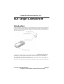
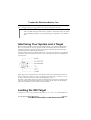
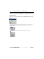
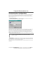
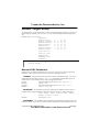
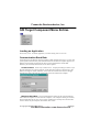
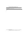
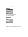
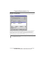
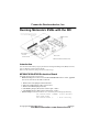
Freescale Semiconductor, Inc.
Debugger
Serial Debug
Interface
SDI target
© Copyright 1987-2003 Metrowerks
For More Information: www.freescale.com
Debugger
Freescale Semiconductor, Inc.
Product Manual
Manual Date
Debugger - SDI
6-Aug-2003
© Copyright 1987-2003 Metrowerks
For More Information: www.freescale.com
Debugger
Freescale Semiconductor, Inc.
SDI Target Component
Introduction
An advanced feature of this debugger for the embedded system development world is the ability
to load different Framework targets. This document introduces the SDI Serial Debug Interface.
The SDI is a Motorola interface that the debugger uses to communicate with an external system
(also called a target system).
With this interface, you can
download an executable program from the environment. The destination of this program is an
external target system, based on a Motorola MCU, that executes the program. the debugger
receives feedback of real target-system behavior.
The debugger fully supervises and monitors the target-system MCU. That is, the debugger controls the CPU execution. You can read and write in internal or external memory (even when the
© Copyright 1987-2003 Metrowerks
Debugger
For More Information: www.freescale.com
Freescale Semiconductor, Inc.
CPU is running); single-step, run, or stop the CPU; and set breakpoints in the code.
Note:
Uninvolved Components As an external MCU executes the
code, the SDI cannot provide memory statistics. This means that you cannot
use the SDI for profiling, coverage analysing, watchpoints, or I/O simulation.
Interfacing Your System and a Target
Motorola designed the SDI around a serial communication link. Any available communication
device of your system (PC or SUN) supports the SDI. The SDI target driver fully handles the
communication protocol between the SDI and your system; loading the SDI target component
automatically includes loading the SDI target driver.
The target hardware must have a BDM connector, for connection to the SDI. You can set the baud
rate (Please see the SDI Default Environment section). The diagram below shows the BDM port
6-pin connector.
SDI-to-target-system communication is serial. Motorola defines the communication protocol in
the CPU 12 Reference Manual, section 8 (Development and Debug Support). However, you do
not need to know this protocol to conduct an SDI debugging session.
The target system supplies power to the SDI, provided that target-system power conforms to the
TTL norm. If it does not, the SDI should have its own supply. Please refer to the SDI hardware
manual, SDI INTERFACE USER’S MANUAL, from Motorola.
Loading the SDI Target
Usually, the PROJECT.INI file specifies the target: Target=Motosil. The MotoSIL driver
© Copyright 1987-2003 Metrowerks
Debugger
For More Information: www.freescale.com
Freescale Semiconductor, Inc.
automatically detects the SDI target connection to your system. However, if the driver detects
nothing, an error message informs you that the target is not connected or that the target is connected to a different port. A Communication Configuration dialog appears, so that you can set the
correct baud-rate and communication-port parameter values. Please see the Communication Configuration section, below.
If the PROJECT.INI file target setting is incorrect, load the SDI driver. From the main menu,
select Component | Set Target..., as shown below. Then choose MotoSIL from the list of possible
targets.
The MotoSIL driver automatically ties to find the SDI target, behaves as described above for
automatic detections.
If MotoSIL does not detect any target, the MotoSIL menu remains in the main menu bar:
After successful target loading, the SDI menu replaces the Target or MotoSIL menu.
© Copyright 1987-2003 Metrowerks
Debugger
For More Information: www.freescale.com
Freescale Semiconductor, Inc.
Communication Configuration
In most situations, the debugger uses its default values to set communication with SDI automatically. In case of any problem, the dialog box below appears, so that you can correct settings.
Make sure that your host-computer parameter values are correct; make sure that the serial communication setting is correct.
Communication Device If your host and target are not connected, or if the connection is not via the expected device, this dialog box appears:
Type the name of an available communication device in the Communication Device edit box, use
the drop-down control to set the baud rate, then click Connect. (The default communication
device is COM1.) If the debugger cannot establish connection with the specified device, a message box lets you try a different communication device. Once communication succeeds, the
debugger saves the communication device as the default for a later debugging session. To exit the
dialog box and the environment, click Cancel.
Note: Saving the communication device and the baud rate through this dialog box
overrides environment variables BAUDRATE and COMDEV of the
DEFAULT.ENV file.
Data Format The SDI data format is 8 data bits, 1 stop bit, no parity, and a variable baud
rate. The default speed is 9600 baud, unless you change this default via the Target-menu selection
SDI | Communication... (please see the dialog box below).
Communication speeds of 1200 through 57600 baud are available, depending on the host-computer hardware.
© Copyright 1987-2003 Metrowerks
Debugger
For More Information: www.freescale.com
Freescale Semiconductor, Inc.
Default Target Setup
As with any target, you can use the Target menu to load the SDI target component, or you can set
the SDI target as a default in the PROJECT.INI file. This file should be in the working directory.
Example of PROJECT.INI file.
[DEFAULTS]
Window0=Source
0
0 50 40
Window1=Assembly 50
0 50 40
Window2=Register 50 40 50 30
Window3=Memory
50 70 50 30
Window4=Data
0 40 50 25
Window5=Command
0 65 50 20
Window6=Module
0 85 50 15
Target=Motosil
[Motorola ESL]
COMDEV=COM2
BAUDRATE=57600
SHOWPROT=1
Note: Please see the core debugger manual for more information about the
PROJECT.INI file.
Motorola ESL Parameters
In normal use, you set these parameters in the PROJECT.INI file once, interactively, during
installation. You use these parameter values in subsequent debugging sessions.
COMDEV This parameter specifies the host-computer communication port. COM1 is the
default communication device for PCs; /dev/ttya is the default communication device for
UNIX systems. To set a different device, follow the appropriate pattern:
For a PC:
Any valid communication device (COM1,COM2,etc.).
Example:
COMDEV=COM2
For SUN:
Any valid communication device (/dev/ttya, etc.).
Example:
comdev=/dev/ttyb
BAUDRATE This parameter specifies the communication baud rate between the host
computer and the target. The default is 9600 baud, but you may set any of these baud rates:
1200, 2400, 4800, 9600, 19200, 28800,
38400, 57600, 115200.
Example:
BAUDRAUTE=19200
SHOWPROT This parameter controls reporting of commands and responses in the command line window. The SHOWPROT value 0 specifies not reporting commands and responses. The
© Copyright 1987-2003 Metrowerks
Debugger
For More Information: www.freescale.com
Freescale Semiconductor, Inc.
SHOWPROT value 1 specifies reporting commands and responses. The Show Protocol checkbox,
of the Communication Device Specification dialog box, is another way to control this feature.
Please see the section Communication Configuration, Communication Device Specification.
EEPROM Programming
To download code or data into on-chip EEPROM, the debugger must know the EEPROM address
range. Use environment variables EEPROM_START and EEPROM_END to convey this information.
EEPROM_START specifies the address of the first byte of EEPROM; EEPROM_END specifies the
address of the last byte of EEPROM.
Example:
EEPROM_START=0x0D00
EEPROM_END=0xFFF
This example specifies EEPROM in the memory range 0xD000 to 0x0FFF. During writes to
these addresses, EEPROM programming automatically downloads a program to modify memory
or variables interactively.
Note: You cannot use these environment variables to program FLASH memory.
© Copyright 1987-2003 Metrowerks
Debugger
For More Information: www.freescale.com
Freescale Semiconductor, Inc.
The Debugger Status Bar for the SDI
Once you have loaded the SDI target component, the debugger status bar gives specific information. From left to right, this information is: the serial-communication baud rate, the running mode,
the target E-clock frequency, and the current MCU-Id.
© Copyright 1987-2003 Metrowerks
Debugger
For More Information: www.freescale.com
Freescale Semiconductor, Inc.
SDI Target Component Menu Entries
Loading an Application
Choose SDI | Load... to load the application you want to debug, such as a.ABS file.
Communication Baud Rate
You should specify the baud rate for host-computer-to-SDI communication early in a session. The
system operates most efficiently at the maximum baud rate that the host computer supports. The
debugger sets this baud rate automatically when it starts communication with the SDI.
However, you can modify this baud rate, as text below explains.
Communication Select SDI | Communication... to display the dialog box below. If you
know the maximum rate your host supports, use the drop-down control to select that rate. (The
SDI does not support 115200). Otherwise, select 57600. If communication fails, the debugger
automatically reduces the baud rate communication succeeds with the host computer.
Maximum Baud Rate The maximum baud rate depends on the speed and interrupt
load of the host computer. For slow notebook computers, or for computers running in a network,
the maximum baud rate may be as low as 19200. A buffered I/O card may allow the maximum
rate of 57600 for any host computer. The default value is 9600.
© Copyright 1987-2003 Metrowerks
Debugger
For More Information: www.freescale.com
Freescale Semiconductor, Inc.
Show Protocol If you check the Show Protocol checkbox, the system reports all commands and responses in the command line window.
Note: Motorola or Metrowerks support personnel use this feature.
© Copyright 1987-2003 Metrowerks
Debugger
For More Information: www.freescale.com
Freescale Semiconductor, Inc.
MCU Selection
To specify the MCU, choose SDI | Set MCU.... This open the MCU Selection dialog box.
This dialog box contains drop-list combo controls for the name and MCU-ID of the currently
selected MCU. Use these controls to make any appropriate changes.
The control selections are from the file MDSEMCU.INI. If the drop-lists do not include the name
or MCU-ID you want, you must update your installation.
The debugger saves your selections, to be the defaults for your next session.
E-clock Frequency
To specify the E-clock frequency, choose SDI | Set MCU Speed.... This opens the Set MCU Speed
dialog box.
This dialog box shows the E-clock frequency that the MCU is to use, typically half the oscillator
frequency. The SDI must know the E-clock frequency for proper BDM communication.
You can type a specific frequency in the edit box. Optionally, you can click the Search button, to
have the debugger test communication with several frequencies, in this order:
8 MHz, 4 MHz, 2 MHz, 1 MHz, 500 kHz, 250 kHz, 125 kHz, 62.5 kHz, 6 MHz, 3 MHz, 1.5
MHz, 750 kHz, 375 kHz, 187.5 kHz, 93.75 kHz, 46.875 kHz, 7 MHz, 3.5 MHz, 1.75 MHz, 875
kHz, 437.5 kHz, 218.75 kHz, 109.375 kHz, 54.687 kHz, 5 MHz, 2.5 MHz, 1.25 MHz, 625 kHz,
312.5 kHz, 156.25 kHz, 78.125 kHz, 39.062 kHz, 32.768 kHz, 16.384 kHz.
If the debugger cannot verify communication, a message so informs you.
At startup, the debugger uses the specified frequency. Should this frequency fail, and if you have
checked the Auto detect checkbox, the debugger tries to find an appropriate frequency.
The debugger saves your selections, to be the defaults for your next session.
© Copyright 1987-2003 Metrowerks
Debugger
For More Information: www.freescale.com
Freescale Semiconductor, Inc.
Memory Configuration
To view the memory layout, choose SDI | Memory Map.... This opens the Memory Configuration
dialog box.
This dialog box shows the default memory configuration for the MCU being used. Check the Auto
select box to have the system load this setup automatically. The system reads memory-layout
information from the specific MCU personality file. The personality-file decomposition is:
00nnnVvv.MEM — nnn is the 3-digit hexadecimal representation of
the MCUid, and vv is the version number.
The system looks up the personality file in the “PROG\MEM” subdirectory of your installation.
Note: In this product version, the Memory Configuration dialog box only displays
the default memory layout.
© Copyright 1987-2003 Metrowerks
Debugger
For More Information: www.freescale.com
Freescale Semiconductor, Inc.
SDI Target Startup File
The debugger executes startup command file STARTUP.CMD right after the system loads the SDI
target driver. This file must be in the working directory. You can use any command in this file,
taking advantage of the large set of commands that Core Debugger User guide introduces.
Example of startup.cmd file contents:
wb 0x0035
0x00
wb 0x0012
0x11
SDI Reset Command File
Choose Reset, from the Target/SDI menu, to execute SDI reset command file RESET.CMD.
This file must be in the working directory. You can use any command in this file.
Note: Entering the RESET command in the Command Line does NOT execute the
reset command file.
Loading the SDI Component
The debugger target component monitors the SDI interface. Loading the SDI target component
includes loading the SDI driver. Load the SDI target component through the PROJECT.INI file.
Alternatively, go to the main menu, select Component | Set Target..., then choose Motosil. The
debugger base installation does not include installation of the SDI target DLL.
On-chip Hardware Breakpoint
You can use an on-chip hardware breakpoint module implement breakpoints. To do so, you must
initialize the environment variable HWBPMODULEADR (in the DEFAULT.ENV file) with the
address of the hardware breakpoint module. Make sure that the line is not in a remark. If you will
not use hardware breakpoints, you may remove the environment-variable line.
Example:
HWBPMODULEADR=0x20
This example shows the value to be used for the M68HC12B32.
© Copyright 1987-2003 Metrowerks
Debugger
For More Information: www.freescale.com
Freescale Semiconductor, Inc.
.
Note: The SDI supports only two hardware breakpoints at the same time. Additional breakpoints must software breakpoints.
Note: If you debug code in FLASH memory, do not set more than two breakpoints.
Note: Actions such as "stepping over” and “stepping out” use one internal breakpoint, so restrict you to just one hardware breakpoint.
© Copyright 1987-2003 Metrowerks
Debugger
For More Information: www.freescale.com
Freescale Semiconductor, Inc.
Running Motorola’s EVBs with the SDI
Introduction
You can use the SDI with any target system that has a background debug mode (BDM) connector,
such as a Motorola evalution boards (EVB).
Please see the section Interfacing Your System and a Target.
MC68HC812A4EVB Evaluation Board
This EVB supports an HC12A4 processor.
• Hardware setup (taken from the Motorola HC12A4EVBUM/D hardware manual, Appendix
F) to run the SDI with the MC68HC812A4EVB:
1. Remove the CSD jumper from header W11.
2. Move the CSP0 jumper to W11 pins 2 and 3.
3. Remove the BKGD jumper (W30).
4. The MODA jumper (W34) must connect pins 1 and 2.
5. The MODB jumper (W42) must connect pins 1 and 2.
•
Software setup to be inserted in the RESET.CMD file of your current project directory:
wb 0x000B 0xF0 //MODE: forces Normal
Exp Wide mode
wb 0x000B 0xF0 //
: this forcing
© Copyright 1987-2003 Metrowerks
Debugger
For More Information: www.freescale.com
Freescale Semiconductor, Inc.
must be done twice!!
wb 0x0011 0x00 //INITRG
wb 0x0010 0x08 //INITRM
wb 0x0012 0x11 //INITEE, move on-chip
EEPROM from $F000
//
to $1000
Note: Motorola’s hardware setup steps 4 and 5 force the HC12A4 operating mode
to Single Chip. This enables starting the background debugger. Subsequently, you must force by software (as shown above in the RESET.CMD file)
the Expanded Wide mode to access the 16 kilobytes of on-board RAM
($C000 - $FFFF).
After the setup above, the new SDI memory map is:
$0000-$01FF, CPU registers, on-chip (MCU)
$0800-$0BFF, user data area, 1 Kilobyte on-chip RAM (MCU)
$1000-$1FFF, user code area, 4 Kilobyte on-chip EEPROM (MCU)
$C000-$FFFF, user code/data area, 16 Kilobytes external RAM (U4, U5A)
Please see as well Motorola’s SDI INTERFACE USER’S MANUAL and MC68HC812A4EVB
manual.
The SDI installation disk includes demo programs; you can load and run all these demos with the
SDI and on the MC68HC812A4EVB.
MC68HC912B32EVB Evaluation Board
This EVB supports an HC912B32 processor.
To run the SDI with the MC68HC912B32EVB:
-You do not need to set any jumpers.
-If necessary, software can download the ROM monitor program directly to the processor EEPROM.
Please see as well Motorola’s SDI INTERFACE USER’S MANUAL and MC68HC912B32EVB
manual.
Connection between SDI and HC12B32EVB
Boards such as the HC12A4EVB have a 10-pin BDM male connector. But boards such as the
HC12B32EVB have a 6-pin BDM male connector. For a 6-pin board connector, use the 6-pin
female connector of the SDI ribbon cable.
Note that the ribbon cable red wire (wire number 1) does not extend to the 6-pin connector. The 6pin connector wires are 4 through 9. Accordingly, cable wire number 4 must connect to pin 1 of
the HC12B32EVB BDM-in / W9 connector.
The number “1” beside the BDM-in connector identifies pin 1. Another way to identify pin 1 of
the connector is to note the square solder pad under the connector, on the top side of the board.
© Copyright 1987-2003 Metrowerks
Debugger
For More Information: www.freescale.com
Freescale Semiconductor, Inc.
Power Supply
The SDI INTERFACE USER’S MANUAL, section 2 (INTERFACE HOOKUPS), explains the SDI
standard interface hook-up, low-voltage interface hook-up, and alternative hook-up conversions.
© Copyright 1987-2003 Metrowerks
Debugger
For More Information: www.freescale.com
Freescale Semiconductor, Inc.
SDI COMMANDS
This section explains the commands specific to the SDI.
Use these commands as you would any others, typing them in the Command Line component or
inserting them into a command file.
For further details about commands, please see the debugger manual appendix, Debugger Commands, as well as the section Command Line Component.
BAUD
––––––––––––––––––––––––
–
Short Description
sets the communication baud rate
Syntax
BAUD [rate]
rate: Specifies the new baud rate; must be one of these decimal integer constants:
1200, 2400, 4800, 9600, 19200, 28800, 38400, 57600.
Description
The BAUD command sets or displays the baud rate for communication between the system controller and the host computer. For maximum performance, the baud rate should be as high as the
host computer can accommodate. The maximum rate is 57600; the default baud rate is 9600.
Without a rate value, the command displays the Communications Baud Rate Specification dialog
box for interactive rate selection. If the host computer cannot support the requested rate, an “Out
of synchronization” alert box appears. Select the RETRY option to retry communication at 9600
baud. Select the ABORT option to exit to the operating system. You also may use the menu to
open the baud rate dialog box.
example: BAUD 57600
Changes the communication baud rate to 57600, the maximum rate.
© Copyright 1987-2003 Metrowerks
Debugger
For More Information: www.freescale.com
Freescale Semiconductor, Inc.
RESET
––––––––––––––––––––––––
–
Short Description
resets the emulation processor
Syntax
RESET
Description
The RESET command resets the emulator and the emulation processor. The system does not execute the reset command file (RESET.CMD).
TARGETRESET
––––––––––––––––––––––––
–
Short Description
resets the SDI target interface
Syntax
TARGETRESET
Description
The TARGETRESET command:
• Resets the target interface,
• Resets the emulation processor,
• Initializes the debugger program counter to the reset vector value, and
• Executes the reset command file (RESET.CMD).
© Copyright 1987-2003 Metrowerks
Debugger
For More Information: www.freescale.com
Freescale Semiconductor, Inc.
21
Contents
SDI Target Component . . . . . . . . . . . . . . . . . . . . . . . . . . 3
Introduction . . . . . . . . . . . . . . . . . . . . . . . . . . . . . . . . . . . . . . . . . . . 3
Interfacing Your System and a Target . . . . . . . . . . . . . . . . . . . . . . . 4
Loading the SDI Target . . . . . . . . . . . . . . . . . . . . . . . . . . . . . . . . . . 4
Communication Configuration. . . . . . . . . . . . . . . . . . . . . . . . . . . . . 6
Default Target Setup . . . . . . . . . . . . . . . . . . . . . . . . . . . . . . . . . . . . 7
Motorola ESL Parameters . . . . . . . . . . . . . . . . . . . . . . . . . . . . . . . . . . . . . . . . . . . . 7
EEPROM Programming . . . . . . . . . . . . . . . . . . . . . . . . . . . . . . . . . . . . . . . . . . . . . 8
The Debugger Status Bar for the SDI . . . . . . . . . . . . . . . . . . . . . . . 9
SDI Target Component Menu Entries . . . . . . . . . . . . . . . . . . . . . . 10
Loading an Application. . . . . . . . . . . . . . . . . . . . . . . . . . . . . . . . . . . . . . . . . . . . . 10
Communication Baud Rate . . . . . . . . . . . . . . . . . . . . . . . . . . . . . . . . . . . . . . . . . . 10
MCU Selection . . . . . . . . . . . . . . . . . . . . . . . . . . . . . . . . . . . . . . . . . . . . . . . . . . . 12
E-clock Frequency . . . . . . . . . . . . . . . . . . . . . . . . . . . . . . . . . . . . . . . . . . . . . . . . 12
Memory Configuration . . . . . . . . . . . . . . . . . . . . . . . . . . . . . . . . . . . . . . . . . . . . . 13
SDI Target Startup File . . . . . . . . . . . . . . . . . . . . . . . . . . . . . . . . . 14
SDI Reset Command File. . . . . . . . . . . . . . . . . . . . . . . . . . . . . . . . 14
Loading the SDI Component . . . . . . . . . . . . . . . . . . . . . . . . . . . . . 14
On-chip Hardware Breakpoint . . . . . . . . . . . . . . . . . . . . . . . . . . . . 14
Running Motorola’s EVBs with the SDI . . . . . . . . . . . . . . . . . . . . 16
Introduction . . . . . . . . . . . . . . . . . . . . . . . . . . . . . . . . . . . . . . . . . . . . . . . . . . . . . . 16
MC68HC812A4EVB Evaluation Board . . . . . . . . . . . . . . . . . . . . . . . . . . . . . . . . 16
MC68HC912B32EVB Evaluation Board . . . . . . . . . . . . . . . . . . . . . . . . . . . . . . . 17
Power Supply . . . . . . . . . . . . . . . . . . . . . . . . . . . . . . . . . . . . . . . . . . . . . . . . . . . . 18
SDI COMMANDS . . . . . . . . . . . . . . . . . . . . . . . . . . . . . 19
BAUD. . . . . . . . . . . . . . . . . . . . . . . . . . . . . . . . . . . . . . . . . . . . . . . 19
RESET . . . . . . . . . . . . . . . . . . . . . . . . . . . . . . . . . . . . . . . . . . . . . . 20
TARGETRESET . . . . . . . . . . . . . . . . . . . . . . . . . . . . . . . . . . . . . . 20
Index . . . . . . . . . . . . . . . . . . . . . . . . . . . . . . . . . . . . . . . . 23
For More Information: www.freescale.com
©Metrowerks, Inc., 1993, 2001
HI-WAVE
22
Freescale Semiconductor, Inc.
For More Information: www.freescale.com
©Metrowerks, Inc., 1993, 2001
HI-WAVE
Index
Freescale Semiconductor, Inc.
Index
23
I
I/O 4
L
Loading an application 10
B
BAUD 19
Baud Rate 6, 10
BAUDRATE 6, 7
BDM 17
BDM connector 4
Breakpoint 14, 15
C
COMDEV 6, 7
Communication 4, 10
Communication Baud Rate 10
Communication Configuration 6
Communication device 6
Connection between SDI and EVBs 17
Coverage 4
M
MC68HC812A4EVB 16
MC68HC912B32EVB 17
MCU 3
MCU selection 12
Memory Map... 13
Motosil 7
P
Power Supply 18
Profiling 4
PROJECT.INI 7
Protocol 4, 11
R
D
Data Format 6
DEFAULT.ENV 6, 14
RESET 20
RESET.CMD 14
S
E
E-clock frequency 12
EEPROM Programming 8
EEPROM_END 8
EEPROM_START 8
EVB 16
F
FLASH 8
H
Hardware Breakpoint 14
HWBPMODULEADR 14
SDI 3
Connection 6
Interfacing 4
Loading 14
Memory Configuration 13
Menu entries 10
Power supply 4
Reset command file 14
Startup file 14
Target Configuration 10
SDI driver 4
Serial communication 4
SHOWPROT 7
Simulation 4
STARTUP.CMD 14
Status Bar 9
System interfacing 4
For More Information: www.freescale.com
©Metrowerks, Inc., 1993, 2001
HI-WAVE
24
Freescale Semiconductor, Inc.
T
Target 3
Target Setup 7
W
Watchpoint 4
For More Information: www.freescale.com
© Copyright 1997 HIWARE
HI-WAVE