1
Freescale Semiconductor, Inc.
Freescale Semiconductor, Inc...
MCUEZMMDS0508/D
FEBRUARY 1998
MCUez
MMDS0508 TARGET
USER’S MANUAL
© Copyright 1998 MOTOROLA and HIWARE AG; All Rights Reserved
For More Information On This Product,
Go to: www.freescale.com
Freescale Semiconductor, Inc.
Important Notice to Users
Freescale Semiconductor, Inc...
While every effort has been made to ensure the accuracy of all information in this document, Motorola
assumes no liability to any party for any loss or damage caused by errors or omissions or by statements
resulting form negligence, accident, or any other cause. Motorola further assumes no liability arising out of
the application or use of any information, product, or system described herein; nor any liability for incidental
or consequential damages arising from the use of this document. Motorola disclaims alll warranties
regarding the information contained herein, whether expressed, implied, or statutory, including implied
warranties of merchantability or fitness for a particular purpose. Motorola makes no representation that the
interconnection of products in the manner described herein will not infringe on existing or future patent
rights, nor do the descriptions contained herein imply the granting or license to make, use, or sell equipment
constructed in accordance with this description.
Information contained in this document applies to REVision (1) MCUez.
The computer program contains material copyrighted by Motorola Inc., first published 1997, and may be
used only under a license such as the License For Computer Programs (Article 14) contained in Motorola’s
Terms and Conditions of Sale, Rev. 1/79.
Trademarks
This document includes these trademarks:
MCUez is a trademark of Motorola Inc.
EXORciser is a trademark of Motorola Inc.
The MCUez development, emulation, and debugging application is based on Hi-Wave, a software
technology developed by HIWARE. Hi-Wave is a registed trademark of HIWARE AG.
AIX, IBM, and PowerPC are trademarks of International Business Machines Corporation.
SPARC is a trademark of SPARC International, Inc.
Sun and SunOS are trademarks of Sun Microsystems, Inc.
UNIX is a trademark of Novell, Inc., in the United States and other countries, licensed exclusively through
X/Open Company, Ltd.
X Window System is a trademark of Massachusetts Institute of Technology.
For More Information On This Product,
Go to: www.freescale.com
Freescale Semiconductor, Inc.
CONTENTS
CHAPTER 1 INTRODUCTION
Freescale Semiconductor, Inc...
1.1 INTRODUCTION . . . . . . . . . . . . . . . . . . . . . . . . . . . . . . . . . . . . . . . . . . . . . . . . . . . . . . . . . . . 1-1
1.2 DEFINITIONS, ACRONYMS AND ABBREVIATIONS . . . . . . . . . . . . . . . . . . . . . . . . . . . . 1-1
CHAPTER 2 MMDS0508 TARGET COMPONENT
2.1 INTRODUCTION . . . . . . . . . . . . . . . . . . . . . . . . . . . . . . . . . . . . . . . . . . . . . . . . . . . . . . . . . . . 2-1
2.2 TARGET/SYSTEM INTERFACE . . . . . . . . . . . . . . . . . . . . . . . . . . . . . . . . . . . . . . . . . . . . . . 2-1
2.2.1 Hardware Connection . . . . . . . . . . . . . . . . . . . . . . . . . . . . . . . . . . . . . . . . . . . . . . . . . . . . 2-1
2.2.2 Loading The MMDS0508 Target. . . . . . . . . . . . . . . . . . . . . . . . . . . . . . . . . . . . . . . . . . . . 2-1
2.3 CONFIGURATION DIALOG. . . . . . . . . . . . . . . . . . . . . . . . . . . . . . . . . . . . . . . . . . . . . . . . . . 2-3
2.3.1 Communication Configuration . . . . . . . . . . . . . . . . . . . . . . . . . . . . . . . . . . . . . . . . . . . . . 2-3
2.3.2 Communication Device Specification Dialog . . . . . . . . . . . . . . . . . . . . . . . . . . . . . . . . . . 2-3
2.3.3 Data Format . . . . . . . . . . . . . . . . . . . . . . . . . . . . . . . . . . . . . . . . . . . . . . . . . . . . . . . . . . . . 2-4
2.4 MCUEZ STATUS BAR FOR THE MMDS . . . . . . . . . . . . . . . . . . . . . . . . . . . . . . . . . . . . . . . 2-4
2.5 MMDS0508 MENU . . . . . . . . . . . . . . . . . . . . . . . . . . . . . . . . . . . . . . . . . . . . . . . . . . . . . . . . . 2-4
2.5.1 MMDS0508 Menu Entries. . . . . . . . . . . . . . . . . . . . . . . . . . . . . . . . . . . . . . . . . . . . . . . . . 2-5
2.5.1.1 Communication . . . . . . . . . . . . . . . . . . . . . . . . . . . . . . . . . . . . . . . . . . . . . . . . . . . . . 2-5
2.5.1.1.1 Baud Rate . . . . . . . . . . . . . . . . . . . . . . . . . . . . . . . . . . . . . . . . . . . . . . . . . . . . . . 2-6
2.5.1.1.2 Show Protocol . . . . . . . . . . . . . . . . . . . . . . . . . . . . . . . . . . . . . . . . . . . . . . . . . . 2-6
2.5.1.2 Memory Map . . . . . . . . . . . . . . . . . . . . . . . . . . . . . . . . . . . . . . . . . . . . . . . . . . . . . . . 2-6
2.5.1.2.1 Configuration . . . . . . . . . . . . . . . . . . . . . . . . . . . . . . . . . . . . . . . . . . . . . . . . . . . 2-6
2.5.1.2.2 About Personality (.MEM) Files . . . . . . . . . . . . . . . . . . . . . . . . . . . . . . . . . . . . 2-6
2.5.1.2.3 Dual-Port RAM . . . . . . . . . . . . . . . . . . . . . . . . . . . . . . . . . . . . . . . . . . . . . . . . . 2-8
2.5.1.2.4 Memory . . . . . . . . . . . . . . . . . . . . . . . . . . . . . . . . . . . . . . . . . . . . . . . . . . . . . . . 2-9
2.5.1.3 Emul Signals . . . . . . . . . . . . . . . . . . . . . . . . . . . . . . . . . . . . . . . . . . . . . . . . . . . . . . . 2-9
2.5.1.3.1 MCU Clock . . . . . . . . . . . . . . . . . . . . . . . . . . . . . . . . . . . . . . . . . . . . . . . . . . . . 2-9
2.5.1.3.2 Reset . . . . . . . . . . . . . . . . . . . . . . . . . . . . . . . . . . . . . . . . . . . . . . . . . . . . . . . . . 2-10
2.5.1.4 Bus Trace . . . . . . . . . . . . . . . . . . . . . . . . . . . . . . . . . . . . . . . . . . . . . . . . . . . . . . . . . 2-10
2.6 DEFAULT TARGET SETUP . . . . . . . . . . . . . . . . . . . . . . . . . . . . . . . . . . . . . . . . . . . . . . . . . 2-10
2.6.1 Motorola ESL Parameters . . . . . . . . . . . . . . . . . . . . . . . . . . . . . . . . . . . . . . . . . . . . . . . . 2-10
2.6.1.1 COMDEV. . . . . . . . . . . . . . . . . . . . . . . . . . . . . . . . . . . . . . . . . . . . . . . . . . . . . . . . . 2-10
2.6.1.2 BAUDRATE. . . . . . . . . . . . . . . . . . . . . . . . . . . . . . . . . . . . . . . . . . . . . . . . . . . . . . . 2-11
2.6.1.3 SHOWPROT . . . . . . . . . . . . . . . . . . . . . . . . . . . . . . . . . . . . . . . . . . . . . . . . . . . . . . 2-11
MCUEZEVS0508/D
iii
For More Information On This Product,
Go to: www.freescale.com
Freescale Semiconductor, Inc.
Freescale Semiconductor, Inc...
CHAPTER 3 BUS ANALYZER
3.1 INTRODUCTION . . . . . . . . . . . . . . . . . . . . . . . . . . . . . . . . . . . . . . . . . . . . . . . . . . . . . . . . . . . 3-1
3.1.1 Trace Modes. . . . . . . . . . . . . . . . . . . . . . . . . . . . . . . . . . . . . . . . . . . . . . . . . . . . . . . . . . . . 3-1
3.1.2 Trace Buffer . . . . . . . . . . . . . . . . . . . . . . . . . . . . . . . . . . . . . . . . . . . . . . . . . . . . . . . . . . . . 3-1
3.1.3 Textual Or Graphical . . . . . . . . . . . . . . . . . . . . . . . . . . . . . . . . . . . . . . . . . . . . . . . . . . . . . 3-1
3.2 USING THE BUS ANALYZER . . . . . . . . . . . . . . . . . . . . . . . . . . . . . . . . . . . . . . . . . . . . . . . . 3-1
3.2.1 Trigger Setup . . . . . . . . . . . . . . . . . . . . . . . . . . . . . . . . . . . . . . . . . . . . . . . . . . . . . . . . . . . 3-3
3.2.2 Sequencer Setup . . . . . . . . . . . . . . . . . . . . . . . . . . . . . . . . . . . . . . . . . . . . . . . . . . . . . . . . . 3-4
3.2.3 Time Tag Clock Setup . . . . . . . . . . . . . . . . . . . . . . . . . . . . . . . . . . . . . . . . . . . . . . . . . . . . 3-7
3.3 COLLECTING DATA . . . . . . . . . . . . . . . . . . . . . . . . . . . . . . . . . . . . . . . . . . . . . . . . . . . . . . . . 3-8
3.3.1 Arming The Analyzer . . . . . . . . . . . . . . . . . . . . . . . . . . . . . . . . . . . . . . . . . . . . . . . . . . . . 3-8
3.3.2 Disarming The Analyzer . . . . . . . . . . . . . . . . . . . . . . . . . . . . . . . . . . . . . . . . . . . . . . . . . . 3-8
3.3.3 Start Emulation . . . . . . . . . . . . . . . . . . . . . . . . . . . . . . . . . . . . . . . . . . . . . . . . . . . . . . . . . 3-8
3.3.4 Status Bar . . . . . . . . . . . . . . . . . . . . . . . . . . . . . . . . . . . . . . . . . . . . . . . . . . . . . . . . . . . . . . 3-8
3.3.5 Halt Data Collection. . . . . . . . . . . . . . . . . . . . . . . . . . . . . . . . . . . . . . . . . . . . . . . . . . . . . . 3-9
3.3.6 Halt Emulation . . . . . . . . . . . . . . . . . . . . . . . . . . . . . . . . . . . . . . . . . . . . . . . . . . . . . . . . . . 3-9
3.3.7 Recording Bus Data . . . . . . . . . . . . . . . . . . . . . . . . . . . . . . . . . . . . . . . . . . . . . . . . . . . . . . 3-9
3.3.8 Trigger Event . . . . . . . . . . . . . . . . . . . . . . . . . . . . . . . . . . . . . . . . . . . . . . . . . . . . . . . . . . . 3-9
3.4 VIEWING COLLECTED DATA . . . . . . . . . . . . . . . . . . . . . . . . . . . . . . . . . . . . . . . . . . . . . . . 3-9
3.4.1 Textual Display . . . . . . . . . . . . . . . . . . . . . . . . . . . . . . . . . . . . . . . . . . . . . . . . . . . . . . . . 3-10
3.4.2 Instructions Only Display . . . . . . . . . . . . . . . . . . . . . . . . . . . . . . . . . . . . . . . . . . . . . . . . 3-11
3.4.3 Graphical Display . . . . . . . . . . . . . . . . . . . . . . . . . . . . . . . . . . . . . . . . . . . . . . . . . . . . . . 3-11
3.4.4 Time Mesasuring . . . . . . . . . . . . . . . . . . . . . . . . . . . . . . . . . . . . . . . . . . . . . . . . . . . . . . . 3-13
3.4.5 ShowLocation . . . . . . . . . . . . . . . . . . . . . . . . . . . . . . . . . . . . . . . . . . . . . . . . . . . . . . . . . 3-13
3.5 ADD / REMOVE ITEMS IN THE TRACE WINDOW . . . . . . . . . . . . . . . . . . . . . . . . . . . . . 3-13
3.6 SCROLLING THE DISPLAY. . . . . . . . . . . . . . . . . . . . . . . . . . . . . . . . . . . . . . . . . . . . . . . . . 3-14
3.6.1 Search For A Frame . . . . . . . . . . . . . . . . . . . . . . . . . . . . . . . . . . . . . . . . . . . . . . . . . . . . . 3-14
3.6.2 Search For Events . . . . . . . . . . . . . . . . . . . . . . . . . . . . . . . . . . . . . . . . . . . . . . . . . . . . . . 3-15
3.6.3 Next Event . . . . . . . . . . . . . . . . . . . . . . . . . . . . . . . . . . . . . . . . . . . . . . . . . . . . . . . . . . . . 3-16
3.6.4 Previous Event . . . . . . . . . . . . . . . . . . . . . . . . . . . . . . . . . . . . . . . . . . . . . . . . . . . . . . . . . 3-16
3.6.5 Search For A Pattern . . . . . . . . . . . . . . . . . . . . . . . . . . . . . . . . . . . . . . . . . . . . . . . . . . . . 3-16
3.7 DUMPING THE BUS ANALYZER DATA TO A FILE . . . . . . . . . . . . . . . . . . . . . . . . . . . . 3-18
CHAPTER 4 MMDS COMMANDS
4.1
4.2
4.3
4.4
4.5
INTRODUCTION . . . . . . . . . . . . . . . . . . . . . . . . . . . . . . . . . . . . . . . . . . . . . . . . . . . . . . . . . . . 4-1
BAUD RATE COMMAND. . . . . . . . . . . . . . . . . . . . . . . . . . . . . . . . . . . . . . . . . . . . . . . . . . . . 4-1
TRIGGER COMMANDS . . . . . . . . . . . . . . . . . . . . . . . . . . . . . . . . . . . . . . . . . . . . . . . . . . . . . 4-2
BUS ANALYZER COMMANDS . . . . . . . . . . . . . . . . . . . . . . . . . . . . . . . . . . . . . . . . . . . . . . . 4-7
TARGET SIGNAL EMULATION COMMANDS . . . . . . . . . . . . . . . . . . . . . . . . . . . . . . . . . 4-15
iv
MCUEZEVS0508/D
For More Information On This Product,
Go to: www.freescale.com
Freescale Semiconductor, Inc.
Freescale Semiconductor, Inc...
4.6 RESET COMMANDS. . . . . . . . . . . . . . . . . . . . . . . . . . . . . . . . . . . . . . . . . . . . . . . . . . . . . . . 4-15
4.7 PROTOCOL COMMANDS . . . . . . . . . . . . . . . . . . . . . . . . . . . . . . . . . . . . . . . . . . . . . . . . . . 4-16
FIGURES
Figure 2-1. Hardware Connection . . . . . . . . . . . . . . . . . . . . . . . . . . . . . . . . . . . . . . . . . . . . . . . . . . 2-1
Figure 2-2. Component Menu . . . . . . . . . . . . . . . . . . . . . . . . . . . . . . . . . . . . . . . . . . . . . . . . . . . . . 2-2
Figure 2-3. Replacing The Target Menu . . . . . . . . . . . . . . . . . . . . . . . . . . . . . . . . . . . . . . . . . . . . . 2-2
Figure 2-4. MotoSIL Menu . . . . . . . . . . . . . . . . . . . . . . . . . . . . . . . . . . . . . . . . . . . . . . . . . . . . . . . 2-3
Figure 2-5. Communication Device Dialog. . . . . . . . . . . . . . . . . . . . . . . . . . . . . . . . . . . . . . . . . . . 2-3
Figure 2-6. MCUez Status Bar . . . . . . . . . . . . . . . . . . . . . . . . . . . . . . . . . . . . . . . . . . . . . . . . . . . . 2-4
Figure 2-7. MMDS0508 Menu . . . . . . . . . . . . . . . . . . . . . . . . . . . . . . . . . . . . . . . . . . . . . . . . . . . . 2-5
Figure 2-8. Communication Device Specification Dialog. . . . . . . . . . . . . . . . . . . . . . . . . . . . . . . . 2-5
Figure 2-9. Memory Configuration Dialog . . . . . . . . . . . . . . . . . . . . . . . . . . . . . . . . . . . . . . . . . . . 2-6
Figure 2-10. Configuration Error Dialog. . . . . . . . . . . . . . . . . . . . . . . . . . . . . . . . . . . . . . . . . . . . . 2-7
Figure 2-11. Open Personality File Dialog . . . . . . . . . . . . . . . . . . . . . . . . . . . . . . . . . . . . . . . . . . . 2-7
Figure 2-12. Target Signals Dialog . . . . . . . . . . . . . . . . . . . . . . . . . . . . . . . . . . . . . . . . . . . . . . . . . 2-9
Figure 3-1. Trace Window . . . . . . . . . . . . . . . . . . . . . . . . . . . . . . . . . . . . . . . . . . . . . . . . . . . . . . . . 3-2
Figure 3-2. Bus Analyzer Configuration Dialog . . . . . . . . . . . . . . . . . . . . . . . . . . . . . . . . . . . . . . . 3-3
Figure 3-3. Bus Analyzer Configuration Dialog (Sequencer Tab) . . . . . . . . . . . . . . . . . . . . . . . . . 3-5
Figure 3-4. Bus Analyzer Configuration Dialog (Time Tag Clock Tab) . . . . . . . . . . . . . . . . . . . . . 3-7
Figure 3-5. Trace Window Elements . . . . . . . . . . . . . . . . . . . . . . . . . . . . . . . . . . . . . . . . . . . . . . . 3-10
Figure 3-6. Trace Window - Graphical Display. . . . . . . . . . . . . . . . . . . . . . . . . . . . . . . . . . . . . . . 3-12
Figure 3-7. Trace Window - Zoom Out . . . . . . . . . . . . . . . . . . . . . . . . . . . . . . . . . . . . . . . . . . . . . 3-12
Figure 3-8. Items Configuration Dialog . . . . . . . . . . . . . . . . . . . . . . . . . . . . . . . . . . . . . . . . . . . . 3-13
Figure 3-9. Item Content Dialog . . . . . . . . . . . . . . . . . . . . . . . . . . . . . . . . . . . . . . . . . . . . . . . . . . 3-14
Figure 3-10. Search For Event Or Pattern . . . . . . . . . . . . . . . . . . . . . . . . . . . . . . . . . . . . . . . . . . . 3-14
Figure 3-11. Search Frame Dialog. . . . . . . . . . . . . . . . . . . . . . . . . . . . . . . . . . . . . . . . . . . . . . . . . 3-15
Figure 3-12. Search Event Specification Dialog . . . . . . . . . . . . . . . . . . . . . . . . . . . . . . . . . . . . . . 3-15
Figure 3-13. Search For Pattern . . . . . . . . . . . . . . . . . . . . . . . . . . . . . . . . . . . . . . . . . . . . . . . . . . . 3-16
Figure 3-14. Dump Bus Analyzer Frames Dialog . . . . . . . . . . . . . . . . . . . . . . . . . . . . . . . . . . . . . 3-18
MCUEZEVS0508/D
v
For More Information On This Product,
Go to: www.freescale.com
Freescale Semiconductor, Inc...
Freescale Semiconductor, Inc.
vi
MCUEZEVS0508/D
For More Information On This Product,
Go to: www.freescale.com
Freescale Semiconductor, Inc.
INTRODUCTION
CHAPTER 1
INTRODUCTION
Freescale Semiconductor, Inc...
1.1
INTRODUCTION
MCUez features target system interfaces that give you the ability to load different target
components of an embedded system. This manual introduces the interfaces related to the
MMDS0508 Modular Development System for the MC68HC05 and MC68HC08 MCU
Families.
The MMDS0508 is an emulator system that provides emulation memory and a bus state
analyzer for MCUs with a CPU05 or CPU08. MCUez uses Motorola’s MMDS to
communicate with a target system.
Using the MMDS interface, an external target system based on a Motorola MCU can
download an executable program from the MCUez environment, execute it, and relay the
results of the real target system behavior to MCUez.
MCUez fully supervises and monitors the target system’s MCU. It also controls CPU
activities such as read and write in internal/external memory (even when the CPU is running)
and single-step/run/stop processes.
NOTE
When an external MCU is executing code, the memory statistics are not
available to the MMDS target component.
1.2
DEFINITIONS, ACRONYMS AND ABBREVIATIONS
DLL
Dynamic Link Library: Windows library file used in dynamic linking.
Dynamic LinkingWindows process used to link a function call in one module to the actual
function in the library module at run time.
MMDS0508 ServerThe MMDS hardware access library responsible for interfacing across the
RS-232 port to the MMDS0508 station.
Modal Dialog
Dialog that requires a response before continuing.
MCU
Micro Controller Unit
MCUEZMMDS0508/D
1-1
For More Information On This Product,
Go to: www.freescale.com
Freescale Semiconductor, Inc.
INTRODUCTION
Emulation Module
Freescale Semiconductor, Inc...
EM
1-2
MCUEZMMDS0508/D
For More Information On This Product,
Go to: www.freescale.com
Freescale Semiconductor, Inc.
MMDS0508 TARGET COMPONENT
CHAPTER 2
MMDS0508 TARGET COMPONENT
Freescale Semiconductor, Inc...
2.1
INTRODUCTION
This chapter describes how set up communication between MCUez and the MMDS0508 and
explains the windows and dialog boxes associated with the process.
2.2
TARGET/SYSTEM INTERFACE
The MMDS0508 box is connected to the RS-232 serial port of your system.
2.2.1
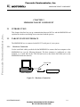
Hardware Connection
Use the serial link cables provided with the MMDS0508 to connect the host computer to the
MMDS0508 box (see the following diagram). The host computer is configured as a data
terminal, i.e. it sends data on the TxD lead and receives data on the RxD lead (refer to the
MMDS0508 hardware manual).
Serial Link
Host Computer
MMDS0508 Box
Figure 2-1. Hardware Connection
MCUEZMMDS0508/D
2-1
For More Information On This Product,
Go to: www.freescale.com
Freescale Semiconductor, Inc.
MMDS0508 TARGET COMPONENT
2.2.2
Loading The MMDS0508 Target
The target component is usually determined by the PROJECT.INI file. To make the MMDS
the target, change the “Target=” line in the PROJECT.INI file to “Target=Motosil”. The
MotoSIL driver automatically attempts to locate the MMDS. If the driver can not locate the
target, an error message appears and informs you that the target is not connected to the
expected port. The Communication Configuration dialog also appears. Using the
Communication Configuration dialog, you can change the baud rate and communication port
parameters. See the Communication Configuration section in this chapter for more details.
Freescale Semiconductor, Inc...
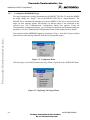
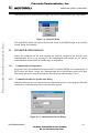
You can also load the MMDS0508 target by selecting Set Target... from the Component Menu
(shown below) and choosing MotoSIL from the list of proposed targets.
Figure 2-2. Component Menu
After the target is successfully loaded, the Target Menu is replaced by the MMDS0508 Menu.
Figure 2-3. Replacing The Target Menu
2-2
MCUEZMMDS0508/D
For More Information On This Product,
Go to: www.freescale.com
Freescale Semiconductor, Inc.
MMDS0508 TARGET COMPONENT
Freescale Semiconductor, Inc...
If the MotoSIL driver does not detect a target, the MotoSIL Menu replaces the Target Menu:
Figure 2-4. MotoSIL Menu
The MMDS0508 Menu will replace the MotoSIL Menu if the MMDS target is successfully
located during later attempts.
2.3
CONFIGURATION DIALOG
Ensure the parameters on the host computer are correctly configured and that the serial
communication device is set correctly. If the configurations and settings are not correct,
communication between MCUez and the target is not possible.
2.3.1
Communication Configuration
In a general way, the communication between MCUez and the MMDS is set automatically. If
MCUez does not detect a target, the Communication Device Specification dialog will open.
This dialog can also be opened selecting the MotoSIL menu and choosing Connect....
2.3.2
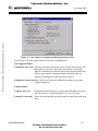
Communication Device Specification Dialog
If the host and target are not connected or the communication device is not properly indicated,
a dialog box, Communications Device Specification, appears:
Figure 2-5. Communication Device Dialog
MCUEZMMDS0508/D
2-3
For More Information On This Product,
Go to: www.freescale.com
Freescale Semiconductor, Inc.
MMDS0508 TARGET COMPONENT
The default device is COM1. To choose another available communication device, enter the
device name in the Communication Device edit box, scroll for the corresponding Baud Rate,
select it, and click Connect.
After the connection with the chosen communication device is established, the settings for
that device are saved for later debug sessions. If the connection fails, a message box will be
displayed and a new communication device can be defined. To close the dialog box without
attempting a new connection, select Cancel.
Freescale Semiconductor, Inc...
NOTE
The communication device and baud rate, which are saved through this dialog,
override the environment variables BAUDRATE and COMDEV
in the
default.env file.
2.3.3
Data Format
MCUez uses the data format: 8 data bits, 1 stop bit, no parity, and a variable baud rate. The
default baud rate is 9600 baud unless it has been redefined through the Communications
Device Specification dialog.
2.4
MCUEZ STATUS BAR FOR THE MMDS
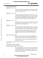
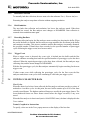
When the MMDS Target Component has been successfully loaded, the MCUez status bar
displays specific information:
Running Mode
Baud Rate
MCU Id
BUS Analyzer Mode
Debugger Status
Figure 2-6. MCUez Status Bar
Displayed from left to right are: the baud rate of serial communication, the MCUez running
mode, the BUS analyzer mode, the name of the connected MCU (depending on the MCU-Id),
and the debugger status.
2.5
MMDS0508 MENU
When the MMDS0508 is successfully set as the target, the MMDS0508 menu appears (see
Loading the MMDS0508 Target in this chapter). The MMDS0508 menu contains functions
specific to the MMDS0508.
2-4
MCUEZMMDS0508/D
For More Information On This Product,
Go to: www.freescale.com
Freescale Semiconductor, Inc.
MMDS0508 TARGET COMPONENT
2.5.1
MMDS0508 Menu Entries
Freescale Semiconductor, Inc...
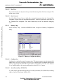
The functions in the MMDS0508 menu are specific to the MMDS0508 and are only available
with this emulator component. To use an item in the MMDS0508 menu, select the menu and
choose the desired function:
Figure 2-7. MMDS0508 Menu
The Communication..., Memory Map..., Emul Signals..., and Bus Trace functions are part of
the MMDS0508 Motorola Modular Development System and are supported by libraries that
consist of dialog boxes and routines that interface with the debugger and hardware.
2.5.1.1
Communication
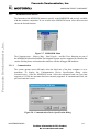
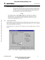
The system operates most efficiently when the baud rate of the host computer is at its
maximum. To display the Communication Device Specification dialog, select
Communication... from the MMDS0508 menu. Select the maximum baud rate your host
supports or 115200, the maximum baud rate currently supported. If communication fails, the
previous baud rate is used.
Figure 2-8. Communication Device Specification Dialog
MCUEZMMDS0508/D
2-5
For More Information On This Product,
Go to: www.freescale.com
Freescale Semiconductor, Inc.
MMDS0508 TARGET COMPONENT
2.8.0.0.1
Baud Rate
The maximum baud rate depends on the speed and the interrupt load of the host computer. The
default value is 9600.
2.8.0.0.2
Show Protocol
Freescale Semiconductor, Inc...
Check the Show Protocol box to display the communication protocol in the Command line
Component. Display from the communication protocol results in superfluous output in the in
the Command Line component. This feature should only be used for advanced debugging
issues.
2.5.1.2
Memory Map
Choose Memory Map... from the MMDS0508 menu to open the Memory Configuration
dialog:
Figure 2-9. Memory Configuration Dialog
2.9.0.0.1
Configuration
Configuration contains the target’s memory setup. The target memory setup is automatically
loaded if the Auto select according to MCU-Id box is checked. MCUez identifies and sets the
memory map through the MCU-Id. To open another configuration, select the Load... button.
To save modifications to the current configuration, select the Save... button.
2.9.0.0.2
About Personality (.MEM) Files
To work properly, the Motosil target has to load the personality file (.MEM file) matching
with the connected Emulation Module (EM).
2-6
MCUEZMMDS0508/D
For More Information On This Product,
Go to: www.freescale.com
Freescale Semiconductor, Inc.
MMDS0508 TARGET COMPONENT
The .MEM file filename is build as follows:
0nnnnVxx.MEM
where ‘nnnn’ is the four hex digit ‘MCU-Id’ number of the MCU connected, and ‘xx’ is a two
digit version number.
Freescale Semiconductor, Inc...
If this file is not found or is not valid, the ‘Configuration Error’ dialog box shown below is
displayed:
Figure 2-10. Configuration Error Dialog
When choosing ‘Cancel’, the connection is not established and the ‘Communication Device
Specification’ dialog is opened.
When choosing ‘Retry’, the ‘Open Personality File’ shown below is displayed
Figure 2-11. Open Personality File Dialog
You can browse to open the required .MEM file.
MCUEZMMDS0508/D
2-7
For More Information On This Product,
Go to: www.freescale.com
Freescale Semiconductor, Inc.
MMDS0508 TARGET COMPONENT
If the .MEM file that you selected is not valid, an error message box pops up, and then the
‘Configuration Error’ dialog box is opened again.
If the selected .MEM file is valid, it is loaded and copied into the \PROG\MEM directory with
‘V00’ as version number (e.g. 00A18V00.MEM).
NOTE
The ‘Memory Configuration’ dialog displays the current memory map.
Freescale Semiconductor, Inc...
When starting MCUez:
If the ‘Auto Select according MCU-ID’ check box is checked, the default
personality file matching with the MCU-ID is automatically loaded. If this check
box is not checked, the previous opened or saved memory map file is
automatically loaded.
The memory configuration can be modified within this ‘Memory Configuration’
dialog and saved into a memory configuration file when clicking the ‘SAVE’
button .
You can load a different memory configuration file (e.g. that you defined
yourself and saved previously) when clicking the ‘LOAD’ button of the
‘Memory Configuration’ dialog.
Also Personality files or any memory configuration files can be loaded with the
LOADMAP command line command.
2.11.0.0.1 Dual-Port RAM
Dual-Port RAM allows you to specify the base address and enable “Real-Time Memory”.
To specify the base address, enter the desired value in the Base Address edit box. To Enable
the “Real-Time Memory”, check the Enable check box. The size of the “Real-Time Memory”
is frozen to 1 kilobyte.
NOTE
Periodical update mode in the Data or Memory component is only possible for
variables or memory positions located in the Dual Port RAM area.
2.11.0.0.2 Memory
Memory allows you to specify the “Real-Time Memory”. The MMDS0508 “Real-Time
Memory” consists of dual-ported memory that can be assigned to any valid RAM or ROM
memory address. While the MMDS0508 is running, MCUez can display and modify the
“Real-Time Memory”. If a portion of the memory overlays internal MCU I/O, RAM, or
EEPROM, that portion can only be displayed, not monitored.
2-8
MCUEZMMDS0508/D
For More Information On This Product,
Go to: www.freescale.com
Freescale Semiconductor, Inc.
MMDS0508 TARGET COMPONENT
2.5.1.3
Emul Signals
Freescale Semiconductor, Inc...
Choose Emul Signals... from the MMDS0508 menu to open the Target Signals dialog shown
below:
Figure 2-12. Target Signals Dialog
The MMDS0508 emulator signals can be specified through this dialog. When the Target
Signals dialog is accessed, the settings are read from the MMDS0508. If you alter the
displayed values and select Ok, the values are written to the MMDS0508. If you check Save
and Reload, the configuration is reloaded when the MCUez debugger is started.
Target Signals dialog can also be used to alter the MCU clock and reset signal connection.
2.12.0.0.1 MCU Clock
MCU Clock allows you to change the MCU clock if the EM is correctly configured (Please
refer to your EM manual).
2.12.0.0.2 Reset
Reset allows you to control the reset signal connection with the target system.
2.5.1.4
Bus Trace
Select Bus Trace from the MMDS0508 menu to run the Bus Analyzer. See the Using The Bus
Analyzer chapter of this document for more details.
2.6
DEFAULT TARGET SETUP
The MMDS target component can be loaded from the Target menu or set as a default target in
the project.ini file, which should be in the working directory.
Example project.ini file:
MCUEZMMDS0508/D
2-9
For More Information On This Product,
Go to: www.freescale.com
Freescale Semiconductor, Inc.
Freescale Semiconductor, Inc...
MMDS0508 TARGET COMPONENT
[DEFAULTS]
Window0=Source
Window1=Assembly
Window2=Register
Window3=Memory
Window4=Data
Window5=Command
Window6=Module
Target=Motosil
[Motorola ESL]
COMDEV=COM2
BAUDRATE=57600
SHOWPROT=0
2.6.1
0
50
50
50
0
0
0
0
0
40
70
40
65
85
50
50
50
50
50
50
50
40
40
30
30
25
20
15
Motorola ESL Parameters
Normally, the Motorola ESL parameters are interactively set during installation. The settings
are stored in the project.ini file and used in the future debugging sessions.
2.6.1.1
COMDEV
The COMDEV parameter specifies the communication device to be used between the host and
MM0508. COM1 is the default communication device for PCs. The default for UNIX systems
is /dev/ttya.
For a PC: Any valid communication device (COM1,COM2,etc.).
Example:COMDEV=COM2
For SUN:Any valid communication device (/dev/ttya, etc.).
Example:comdev=/dev/ttyb
2-10
MCUEZMMDS0508/D
For More Information On This Product,
Go to: www.freescale.com
Freescale Semiconductor, Inc.
MMDS0508 TARGET COMPONENT
2.6.1.2
BAUDRATE
BAUDRATE, the rate of serial communication between the target and host systems, is preset
to 9600 bauds and may be overwritten by one of the following baud rates:
1200, 2400, 4800, 9600, 19200, 28800, 38400, 57600, or 115200.
Example:BAUDRAUTE=19200
Freescale Semiconductor, Inc...
2.6.1.3
SHOWPROT
SHOWPROT determines the display of the communication protocol. The value is set to 0 or 1
(1 to show the communication protocol, 0 to hide it) at the first communication attempt with
the target. You can check the Show Protocol checkbox in the Communication Device
Specification dialog if you want to display the communication protocol in a Command Line
window.
MCUEZMMDS0508/D
2-11
For More Information On This Product,
Go to: www.freescale.com
Freescale Semiconductor, Inc.
Freescale Semiconductor, Inc...
MMDS0508 TARGET COMPONENT
2-12
MCUEZMMDS0508/D
For More Information On This Product,
Go to: www.freescale.com
Freescale Semiconductor, Inc.
BUS ANALYZER
CHAPTER 3
BUS ANALYZER
Freescale Semiconductor, Inc...
3.1
INTRODUCTION
Except for the emulation of the target system MCU, the most important feature that can be
offered by a microcontroller development tool is an instrument to analyze program execution
activities on the target MCU bus. This analysis allows the user to determine what is occurring
in a system without actually affecting it.
NOTE
The Bus analyzer in the MMDS0508 shows the logical state of the MCU bus. It
does not show signal hold and setup times.
3.1.1
Trace Modes
To gather pertinent bus data, the Bus analyzer can be operated in different modes. The various
trace modes of the Bus analyzer make it possible to choose the actions to take when a certain
pattern (event) or sequence of patterns appears on the bus. To trigger the Bus analyzer, define
the desired bus state(s) as terms and select the desired sequence of terms as a trigger event.
3.1.2
Trace Buffer
The trace buffer contains 8,192 entries, or frames, each of which stores 96 bits. When the Bus
analyzer is activated and the emulator is running, a frame of the selected type is strobed into
the trace buffer for each bus cycle. When the event(s) to trigger the analyzer has occurred in
the specified sequence, only the specified number of additional frames are stored.
3.1.3
Textual Or Graphical
The Bus analyzer can display the data either textually or graphically. Use the horizontal and
vertical scroll bars, as in other Windows applications, to move around the display.
MCUEZMMDS0508/D
3-1
For More Information On This Product,
Go to: www.freescale.com
Freescale Semiconductor, Inc.
BUS ANALYZER
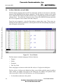
3.2
USING THE BUS ANALYZER
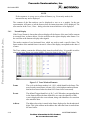
The Bus analyzer functions like any MCUez component, and has its own menu to control the
features of the MMDS0508 Bus analyzer hardware. The Bus Analyzer window is also called
Trace. Indeed the Bus Analyzer matches with the Trace Component and can also be loaded by
choosing Open... Trace from the Component menu. Choose the MMDS0508 menu and select
Bus Trace to open the Trace window or the Bus Analyzer.
Freescale Semiconductor, Inc...
From the user's perspective, using the Bus analyzer requires three steps. These steps are,
defining the data collection parameters, collecting the desired bus data (running the program),
and viewing the collected data.
Figure 3-1. Trace Window
The Bus analyzer contains setup pages for these functions:
•
Triggers
•
Pattern
•
Sequencer
•
Time Tag Clock
These setup pages are shown as tabs in the Bus Analyzer Configuration dialog box.
The Bus Analyzer Configuration dialog box allows you to define symbolic names for address
values. When you change setup pages in the dialog box, the address and symbolic name
values must match. If there is an inconsistency, you will be prompted to:
•
Use the address and remove the symbol.
3-2
MCUEZMMDS0508/D
For More Information On This Product,
Go to: www.freescale.com
Freescale Semiconductor, Inc.
BUS ANALYZER
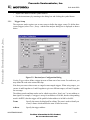
3.2.1
•
Replace the address with the symbol address.
•
Fix the inconsistency by returning to the dialog box and clicking the symbol button.
Trigger Setup
Freescale Semiconductor, Inc...
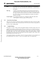
The sequencer mode requires one or more terms to define the trigger events. To define these
events (triggers) select Trace | Setup... and the Bus analyzer dialog box is displayed as shown
below.
Figure 3-2. Bus Analyzer Configuration Dialog
Use the Triggers tab to define a trigger in terms of from one to four events. For each term, you
may define the read-write actions and clips.
Note that you can use these terms as ranged or non-ranged triggers. When using ranges, you
can use A and B together or C and D together to give two different ranges, or B and C together
for one range.
The address masks and data masks can be edited to provide a “don’t care” on any address or
data signal. For example, if a trigger is set up for an address of 0x1000, but the corresponding
mask is 0xFFFE, then the trigger will be qualified when address is 0x1000 or 0x1001.
Terms
Specify the term to be displayed for editing. The term is used to identify an
event (A frame which satisfies the term is called an event).
Address
Specify the trigger address .
MCUEZMMDS0508/D
3-3
For More Information On This Product,
Go to: www.freescale.com
Freescale Semiconductor, Inc.
BUS ANALYZER
Data
Specify the trigger data .
Strobes
Specify the state of R/W on which to trigger.
Group A Clips
Toggle to specify each logic clip as High, Low or Don’t Care.
The clips buttons show the Group A logic clips with their respective colors.
Freescale Semiconductor, Inc...
Logic clips are used to trace the signals in your target system as it runs under the control of the
software. When a trigger occurs, a breakpoint is provided that shows you the states of
significant logic signals before, at, and after the breakpoint.
3.2.2
Invert
To specify that a term, previously defined as triggered within a range, is to
be triggered outside that range, select Invert.
Disable
To disable the trigger for a specific term, select Disable.
Clear
To clear all the changes on the Bus Analyzer Configuration press Clear.
Sequencer Setup
To choose one of the recording modes, select the menu item Trace | Setup... which pops up the
Bus Analyzer Configuration dialog box and then click on the tab labelled Sequencer (see
figure below).
In Non-triggered modes (continuous and counted modes), the collection does not stop until
the analyzer is terminated (Analyze stpos when execution of the application stops or when the
bus analyzer is disarmed).
In triggered modes, the defined terms are used to track the occurrence of events, and the
collection of data is stopped based on some combination of the events. Each term has an
associated Pre Event count which will count events for that term. The sequencer condition
will use that term when the count is reached.
An event is a pattern of bus signals (which can include addresses and data values) to which the
analyzer is connected by logic clips and miscellaneous MCU signals. An event can also be the
negation of a defined pattern. Each signal can be defined as asserted, negated, or ignored
(don't care).
3-4
MCUEZMMDS0508/D
For More Information On This Product,
Go to: www.freescale.com
Freescale Semiconductor, Inc.
Freescale Semiconductor, Inc...
BUS ANALYZER
Figure 3-3. Bus Analyzer Configuration Dialog (Sequencer Tab)
Click on one of the nine option buttons to select the recording mode:
Non-Triggered Modes:
Continuous: All Cycles Provides a real-time, non-invasive trace of MCU bus activities. The
Bus analyzer stores all cycles. When used in this way, the Bus
analyzer continuously records bus data in the trace buffer whenever
the user target system is being emulated. No qualifications for
triggering or halting data collection can be defined.
Continuous: Events OnlyStores all events. Events are defined by the terms set up in the
Triggers dialog box.
Counted Modes:
Counted: All Cycles
Configures the Bus analyzer to record a specified number of cycles.
The user can trace a specified number of cycles of all types.
Counted: Events Only Stores all events until the specified count is reached, then collection
stops.
MCUEZMMDS0508/D
3-5
For More Information On This Product,
Go to: www.freescale.com
Freescale Semiconductor, Inc.
BUS ANALYZER
Triggered/Sequential Modes:
Sequential: A + B + C + D
Select this option for the bus analyzer to start recording after either
event A or B or C or D. Storing data terminates after the specified
number of post-trigger cycles.
Freescale Semiconductor, Inc...
Sequential: A + B -> C + D
Select this option to start the bus analyzer on either of two events
(event A or B) followed by either of two other events (event C or D).
The sequencer can be simplified to involve fewer than four events
by leaving unused events defined with all signals ignored. Data
storage ends after the specified number of post-trigger cycles.
Sequential: A -> B -> C -> D
Select this option to start the bus analyzer after four events, A then
B then C then D, occuring in sequence. Storing data terminates after
specified number of post-trigger cycles.
Sequential: A -> B -> C, D<Select this option to start the bus analyzer on cycles of 3 events in
sequence, A then B then C, provided that the fourth event, D remains
false. When the fourth event, D occurs, the sequence starts again
with the first event. This sequence can be used as a three-event
sequence by leaving event D defined with all signals ignored.
Storing data terminates after specified number of post-trigger
cycles.
Nth Event After A+B+C+D
Select this option for the bus analyzer to begin storing data that
matches event A, event B, event C, and event D, until Nth event is
stored. Then the next 4096 cycles are stored. This allows for a
maximum of 4096 events to be stored (including the Nth event),
followed by 4096 cycles.
For all Triggered/Sequential modes, data storage ends after the specified number of posttrigger cycles.
Counted/Sequential Recording Mode:
Terminal Count/Post Trigger Cycles (1..8191)
Enter a number in the range of 1 to 8191. If one of the counted modes
was selected, this number is the count of bus cycles to trace. If one
of the sequential modes was selected, this is the number of posttrigger cycles to trace. If one of the continuous recording modes was
selected, this value is ignored.
3-6
MCUEZMMDS0508/D
For More Information On This Product,
Go to: www.freescale.com
Freescale Semiconductor, Inc.
BUS ANALYZER
Stop the emulator when recording completes
The stop of the collection of bus cycles does not stop the emulation unless
this check box is checked. Click on the check box Stop the emulator when
recording completes to enable or disable this feature. Then click the OK
button to apply your choice and close the dialog box.
Freescale Semiconductor, Inc...
NOTE
The terminal count or post trigger cycles are valid only for counted or
sequential modes. For a counted mode, this field specifies the number of cycles
to be stored. For a sequential mode, this field specifies the number of cycles to be
stored after the trigger sequence occurs.
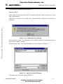
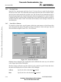
3.2.3
Time Tag Clock Setup
The Bus analyzer uses a clock for the time tag, which provides a time reference value in every
frame of the trace buffer. To change the clock, select the menu entry Trace | Setup... and then
click on the tab labelled Time Tag Clock.
Use this dialog box to specify the clock frequency for time stamping frames in the Bus
analyzer.
Figure 3-4. Bus Analyzer Configuration Dialog (Time Tag Clock Tab)
MCUEZMMDS0508/D
3-7
For More Information On This Product,
Go to: www.freescale.com
Freescale Semiconductor, Inc.
BUS ANALYZER
Clock Frequency In the Clock Frequency area, select one clock frequency to be used; either
an internal oscillator at 1, 2, 4, 8, or 16 Mhz, a bus Clock or a Programmable
clock. In general, the faster clock rates provide higher resolution and are
appropriate for faster emulator clock rates.
Freescale Semiconductor, Inc...
The programmable clock has to be programmed over a range of clock rates from 50 to 50,000
Hz. Entering a Nominal value causes the closest Actual value to be calculated and used. If the
nominal value is an integer that is a quotient of dividing 500,000 Hz by an integer, the
nominal value is also the actual value. If this is not the case, the nominal value is rounded up
to the next valid frequency and that frequency is displayed as the actual value.
Click on the OK button to apply your choice.
Close the dialog box.
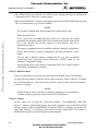
3.3
COLLECTING DATA
When the emulator and the Bus analyzer have been initialized, and the logic clips in the
defined events that are used (if any) have been connected, emulation can begin.
3.3.1
Arming The Analyzer
To collect data the Bus analyzer has to be armed. Choose the menu entry Trace | Arm Analyzer
to arm the Bus analyzer. After the Arm Analyzer entry is clicked, the entry changes to Disarm
Analyzer.
3.3.2
Disarming The Analyzer
To stop the analyzer, select the entry Trace | Disarm Analyzer. After the Disarm Analyzer
entry is clicked, the entry changes to Arm Analyzer.
The status of the Bus analyzer is shown in the status bar of the main window.
3.3.3
Start Emulation
To begin emulation use the command Run | Continue in MCUez or any other command that
starts program execution. Emulation continues until it is stopped by either a breakpoint by the
Bus analyzer or manually. When the emulation stops, the data in the Bus analyzer window is
updated (see below).
3.3.4
Status Bar
When the Bus analyzer is activated, the Bus analyzer status shown on the status bar at the
bottom of the main window changes to Armed, to indicate that the Bus analyzer is ready to
collect data. When emulation begins, the MCU status shown on the status bar changes to
RUNNING. Whenever the Bus analyzer collects data, the Bus analyzer state changes to
ANALYZING.
3-8
MCUEZMMDS0508/D
For More Information On This Product,
Go to: www.freescale.com
Freescale Semiconductor, Inc.
BUS ANALYZER
3.3.5
Halt Data Collection
To manually halt data collection, the user must select the submenu Trace | Disarm Analyzer.
Disarming the analyzer stops data collection without stopping emulation.
3.3.6
Halt Emulation
Freescale Semiconductor, Inc...
The stop halts data collection and emulation, but leaves the analyzer armed. When data
collection has ceased, the Bus analyzer state changes to DISARMED. Data collection is
resumed when emulation starts again.
3.3.7
Recording Bus Data
When data collection begins, the Bus analyzer starts recording bus data into the buffer. When
the end of the buffer is reached, the Bus analyzer wraps around to the first frame in the buffer
and continues recording. This process continues until the Bus analyzer is manually disarmed,
the specified number of frames have been recorded, or the specified number of post-trigger
cycles following the trigger event, have been recorded.
3.3.8
Trigger Event
When a trigger event is detected, the event cycle is latched into the buffer and the Bus
analyzer continues recording data until the specified number of post-trigger cycles has been
collected. When the required post-trigger cycles have been collected, the Bus analyzer stops
collecting data, and the status changes to DISARMED.
With the first post-trigger cycle, the Bus analyzer automatically begins searching for the next
trigger event.
If other events occur while collecting the post-trigger cycles for the first event, the Bus
analyzer marks those event cycles while continuing to collect the post-trigger cycles.
3.4
VIEWING COLLECTED DATA
View Cycles
When the desired cycles have been collected, the Bus analyzer software provides a variety of
methods to view those cycles. At this point, the trace buffer contains up to 8192 of the most
recently stored frames. The highest numbered frames are usually the post-trigger frames. The
lower-numbered frames are those frames stored before the trigger occurred, if any were
stored.
When the Bus analyzer is deactivated (not in ANALYZING state), the data is displayed in the
Trace window.
Textual, Graphical or Instructions
To specify, select one in the Trace popup menu to set the display of the bus data.
MCUEZMMDS0508/D
3-9
For More Information On This Product,
Go to: www.freescale.com
Freescale Semiconductor, Inc.
BUS ANALYZER
NOTE
If the sequencer is set up not to collect all frames (e.g. Event only modes) the
instructions may not be displayed.
The contents of the Bus analyzer can be displayed as text or as a graphic. In the text
representation, all frames or just the frames where an instruction starts, can be displayed. The
user can also in the Trace | Items... dialog select the items which have to be displayed.
3.4.1
Textual Display
Freescale Semiconductor, Inc...
If the Textual format is chosen the software displays all the frames of the trace buffer contents
in a textual form, as shown below. Use the scroll bar at the right to display other frames. Use
the scroll bar at the bottom to display other signals.
The marker consists of two horizontal lines, which are used to mark a specific frame. The
frame number of the marked frame is inverted. A line of the display corresponds to the data of
a frame.
The Trace window contains the following basic items described below. It is possible to add or
remove any item. Please see section Adding / Removing Items in the Trace Window.
Figure 3-5. Trace Window Elements
Frame
The cycle or the frame number is 0 - 8191, which identifies the frame. The
most recently stored frame is frame 8191 (or the highest-numbered frame
that has been stored when less than 8192 frames have been stored).
Events
The defined Trigger identifier is A, B, C, or D. When the corresponding data
in the frame matches the data defined for an event, the identifier of that
event is displayed in the event column, along with identifiers of events that
also match the data.
Address
The address bus value is stored in the frame; displayed as four hexadecimal
digits. This is the address on the address bus when the frame is strobed into
the trace buffer.
3-10
MCUEZMMDS0508/D
For More Information On This Product,
Go to: www.freescale.com
Freescale Semiconductor, Inc.
Freescale Semiconductor, Inc...
BUS ANALYZER
Data
The data bus value is stored in the frame; displayed as two hexadecimal
digits. This is the value on the data bus when the frame is strobed into the
trace buffer.
Time Tag
Contains a representation of the time tag count stored when the frame is
strobed into the trace buffer. When the bus clock is the time tag clock, the
time tag is a number of time tag clock cycles. When a clock other than the
bus clock is chosen, the time tag is displayed as a number of seconds or
fractions of seconds.
Control Signals The remaining fields in the Trace dialog box contain the values of the
control signals or of the two groups of the logic clips.
3.4.2
Instructions Only Display
If the Instructions format is chosen the software only displays those frames of the trace buffer
contents in a text format where an instruction starts. The Instructions format is not possible in
the Events Only recording mode.
3.4.3
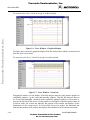
Graphical Display
The figures 3-6 and 3-7 below shows the graphical display of the Bus analyzer data. The
graphical representation of the Bus analyzer data gives a better overview than the textual one.
Switching between the different display formats can easily be done at any time by selecting
the menu entries in the Trace menu. The leftmost sections of the figure display a textual
description of the current frame with information about frame number, events, values on the
data and address bus, time tag value, etc.
In the graphical display it is possible to 'zoom in' or 'zoom out' either to see more details or to
get a better general view. Zoom in / Zoom out are available in the Trace popup menu.
MCUEZMMDS0508/D
3-11
For More Information On This Product,
Go to: www.freescale.com
Freescale Semiconductor, Inc.
BUS ANALYZER
Freescale Semiconductor, Inc...
To zoom in select Trace | Zoom In or type 'I' on the keyboard.
Figure 3-6. Trace Window - Graphical Display
The figure above shows the graphical display of the Bus analyzer data which is zoomed in and
therefore shows more detail.
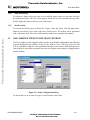
To zoom out select Trace | Zoom Out or type O on the keyboard.
Figure 3-7. Trace Window - Zoom Out
Dragging the marker over the display of the Bus analyzer data may also generate updates in
component windows, e.g. the source and assembly windows. Thus the Bus analyzer data can
be viewed and thoroughly examined in the continually updated windows as the marker is
moved with the help of the cursor over the graphic or text display of the Bus analyzer data. In
Graphical mode, the vertical bar indicates the position of the marker and displays all the
information of the current frame. In Textual and Instructions modes, the horizontal bar
indicates the position of the marker and displays the information for the current trace buffer.
3-12
MCUEZMMDS0508/D
For More Information On This Product,
Go to: www.freescale.com
Freescale Semiconductor, Inc.
BUS ANALYZER
3.4.4
Time Mesasuring
To reference a frame with a tag value of zero, hold the mouse arrow over an entry and click
the right mouse button. The Trace menu appears. Select Set Time Base and the time tag values
will be displayed relative to the bus cycle of the frame.
3.4.5
ShowLocation
Freescale Semiconductor, Inc...
To activate the ShowLocation selection for a frame, select the frame, click the right mouse
button to activate the Trace menu, and select ShowLocation. The marker can be positioned
with a left mouse click. The source and assembly windows are automatically updated.
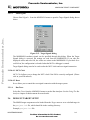
3.5
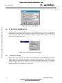
ADD / REMOVE ITEMS IN THE TRACE WINDOW
The Trace window can be supplied with new items. In the default configuration, the following
items are displayed in the window: Frame, Events, Address, Data, Time Tag, Instruction and
R/W. It is possible to add new items (predefined and given in a list box in this dialog) and to
remove them. It is possible to permute items in text or graphic mode simply by dragging them
into the window.
Figure 3-8. Items Configuration Dialog
To edit an item, to set its color or to give a specific name, select More.
MCUEZMMDS0508/D
3-13
For More Information On This Product,
Go to: www.freescale.com
Freescale Semiconductor, Inc.
Freescale Semiconductor, Inc...
BUS ANALYZER
Figure 3-9. Item Content Dialog
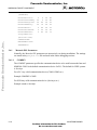
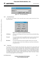
3.6
SCROLLING THE DISPLAY
Scrolling can be done in different ways. The scrollbars can be used as in Windows
applications or the display can be scrolled to a specific trace buffer frame. It is also possible to
search for one or more of the events that are defined to trigger the Bus analyzer or to search
for a specific pattern (see below).
Figure 3-10. Search For Event Or Pattern
3.6.1
Search For A Frame
Select Trace | Go to Frame... to search for an occurrence of a frame and enter the desired
frame number. If a frame with this number is found, the frame is selected. If the selected frame
is not visible, the Bus analyzer window is scrolled to make the frame visible. If the frame
number is bigger than the last frame stored in the trace buffer, the Bus Analyzer scrolls to
display the last frame availabel in the trace buffer.
3-14
MCUEZMMDS0508/D
For More Information On This Product,
Go to: www.freescale.com
Freescale Semiconductor, Inc.
BUS ANALYZER
Figure 3-11. Search Frame Dialog
Freescale Semiconductor, Inc...
3.6.2
Search For Events
To search for an occurrence of an event select one or more events in the Search Event
Specification box.
Figure 3-12. Search Event Specification Dialog
3.6.3
OK Button
If you press the OK button, the selected event(s) is(are) stored and the dialog
box closes.
Forward
To search forward select Forward and the search event is set to the selected
event and a search is done to find the next frame which matches the
specified event.
Backward
To search backward select Backward and the search event is set to the
selected event and a search is done to find the previous frame which matches
the specified event.
Next Event
To search for the next occurrence of the selected events, open the Trace pup-up menu and
select Search | Next Event. This command searches forward from the selected frame to find
the next frame which matches the specified event. The Next Event command can also be
activated without opening the Trace menu by pressing the key N on the keyboard, without
activating the Trace menu. If a frame is found, this frame is selected. If the selected frame is
not visible, the Bus analyzer window scrolls to make the frame visible. If no frame is found,
an error message appears in an error dialog box.
MCUEZMMDS0508/D
3-15
For More Information On This Product,
Go to: www.freescale.com
Freescale Semiconductor, Inc.
BUS ANALYZER
3.6.4
Previous Event
Open the Trace pop-up menu and select Search | Previous Event to search for the previous
occurrence of the event. This command searches backwards from the selected frame to find a
previous frame which matches the specified event. The Previous Event command can also be
activated by pressing the key P on the keyboard, without activating the Trace menu. If a frame
is found, this frame is selected. If the selected frame is not visible, the Bus analyzer window is
scrolled to make the frame visible. If no frame can be found, an error message is shown in an
error dialog box.
Freescale Semiconductor, Inc...
3.6.5
Search For A Pattern
To search for a frame with a specific pattern, define the search pattern, to find all stored bus
cycles that match the pattern. The pattern consists of an address, a data word, logic clips and
four miscellaneous signals. Select Trace | Search|Pattern...
Figure 3-13. Search For Pattern
Within the above dialog box, the search pattern can be defined in the same way as it is defined
in the Trigger Specification Dialog Box.
The Bus analyzer will look at specific collected cycles, match the specific frame that shows
the pattern and display this area in the window of the Debugger.
Address
Specify the Address that should be matched.
Data
Specify the Data value that should be matched.
3-16
MCUEZMMDS0508/D
For More Information On This Product,
Go to: www.freescale.com
Freescale Semiconductor, Inc.
BUS ANALYZER
Strobes
Specify the state of R/W and LIR-X that should be matched.
Group A Clips
Toggle to specify each logic clip as High, Low or Don’t Care.
The clips buttons show the Group A and B logic clips with their respective colors.
Freescale Semiconductor, Inc...
Logic clips are used to trace the signals in your target system; the way they run under the
control of the software. When a trigger occurs, a breakpoint is provided that shows the states
of significant logic signals before, at, and after the breakpoint. That can be used as a pattern to
match.
Invert
To match any frame without the defined pattern select Invert.
OK Button
To store the specified values, select OK then close the box.
Cancel Button
To remove the dialog box without any parameter being changed, select
Cancel.
Next Pattern
To search for the next occurrence of the pattern select the entry Trace
|Search | Next Pattern. If the pattern is not found, an error message is shown
in an error dialog box.
Previous Pattern Select Trace |Search | Previous Pattern to search for the previous occurrence
of the pattern. If the pattern is not found, an error message is shown in an
error dialog box.
MCUEZMMDS0508/D
3-17
For More Information On This Product,
Go to: www.freescale.com
Freescale Semiconductor, Inc.
BUS ANALYZER
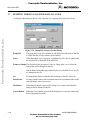
3.7
DUMPING THE BUS ANALYZER DATA TO A FILE
Freescale Semiconductor, Inc...
To dump the Bus analyzer data to a file, open the Trace pop-up menu and select Dump...
Figure 3-14. Dump Bus Analyzer Frames Dialog
Dump File
The group box Dump File contains an edit field where the name of the file
to which the data is to be written, can be entered.
Select
When the button Select is pressed, a standard file select box is opened and
the selected file is displayed in the edit field.
Frames to Dump The elements in the group box Frames to Dump allow you to select the
frames that will be dumped to the file.
Just the frames within the range defined by the two edit fields From: and To:
are dumped to the file.
All
To dump all the frames within the selected range to the file, select All.
Instructions
To dump just the frames where an instruction starts (and instruction is in the
selected range), select Instructions.
OK Button
When the OK button is pressed, the dialog box is removed and the Bus
analyzer data is dumped to the file.
Cancel Button
When the Cancel button is pressed, the dialog box is removed without any
data being dumped to a file.
3-18
MCUEZMMDS0508/D
For More Information On This Product,
Go to: www.freescale.com
Freescale Semiconductor, Inc.
MMDS COMMANDS
CHAPTER 4
MMDS COMMANDS
Freescale Semiconductor, Inc...
4.1
INTRODUCTION
This section describes MMDS-specific commands. MMDS-specific commands are typed in
the Command Line component or inserted into a command file.
For further details about commands, refer to the MCUez Debugger User’s Manual.
4.2
BAUD RATE COMMAND
BAUD
Description:
Syntax:
baud rate.
BAUD [rate]
rate: Specifies the new baud rate, and must be an integer constant with
one of the following specific values (decimal):
1200, 2400, 4800, 9600, 19200, 28800, 38400, 57600, 115200.
Description:
The BAUD command sets the baud rate for communication between the system controller and
the host computer. For maximum performance, the baud rate should be set as high as the host
computer can accommodate. The maximum rate is 115200; the default baud rate is 9600.
If no baud rate is entered, the command displays the Communications Baud Rate
Specification dialog window for interactive selection of the baud rate. If the system does not
support a baud rate, a red error message, “Error: <baud rate> is not a supported baud rate.”is
displayed in the Command Line window.
Example:
BAUD 57600
Changes the communication baud rate to 57600.
MCUEZMMDS0508/D
4-1
For More Information On This Product,
Go to: www.freescale.com
Freescale Semiconductor, Inc.
MMDS COMMANDS
4.3
TRIGGER COMMANDS
CT
Description:
Syntax:
clear trigger.
CT <list> | *
list: A list of trigger identifiers.
*: All triggers (A, B, C and D).
Freescale Semiconductor, Inc...
Description:
The CT command clears the values of specified bus analyzer triggers (events), A, B, C and/or
D. The command also disables the cleared triggers. The trigger values are set by the Set
Trigger (ST) command, and the bus analyzer configuration dialog windows. Triggers are
enabled by the Trigger Enable (TE) command; Triggers are disabled by the Trigger Disable
(TD) command.
Examples:
CT A B
Clears triggers A and B.
CT *
Clears all triggers.
When clearing a trigger which is part of a range, the second trigger in the range is cleared at
the same time.
Example:
If a range is defined between triggers C and D, CT C clears both trigger C and D.
4-2
MCUEZMMDS0508/D
For More Information On This Product,
Go to: www.freescale.com
Freescale Semiconductor, Inc.
MMDS COMMANDS
Freescale Semiconductor, Inc...
ST
Description:
Syntax:
set trigger.
ST[<id> [[!] [(<address> |<address range> | ,)
[(<data> | <data range> | ,)
[(<clips> | ,)[LIR= (X | H | L)]]]] [;R | ;W|
;RW] [;D] ]]
Description:
The ST command sets the value of one of the four bus analyzer triggers. If value is set, or if
only the triggered id is entered, the command interpreter displays the Trigger Specification
dialog window, with which the user sets a trigger value interactively.
id
Specifies the trigger id of the analyzer trigger, A, B, C, or D.
!
The inversion operator, which applies to the entire trigger, as defined. When ! is
specified, and an address, data value, and clip value are specified, the trigger
occurs when the address is not the specified value, or the data value is not the
specified value, or the clip value is not the specified value. When ! is specified
and a range is specified, the trigger occurs at values outside the range and also at
the lowest value in the range.
address
An address to which a trigger is set. The address is specified with an address
constant, as follows:
<address>[:<mask>]
When a mask is entered, only the bits of the address that correspond to ones in the mask are
used in the comparison.
address rangeA range of addresses within which a trigger is set. The address range can
be specified with a start and end address constant, or with a starting address
and a length value, as follows:
<start-address>[:<mask>][..<end-address>]
or
<start-address>[:<mask>][::length]
When a mask is entered, only the bits of the address that correspond to one bits (1s) in the
mask are used in the comparison. When a length and mask are entered, the length is added to
the start address and the mask is applied to the start address and sum to obtain the end address.
,
The comma indicates that the address, address range, data, data range, clips, or clips
range has been omitted. The omitted item is ignored in the trigger.
MCUEZMMDS0508/D
4-3
For More Information On This Product,
Go to: www.freescale.com
Freescale Semiconductor, Inc.
MMDS COMMANDS
data
A data value that defines the trigger. The value is specified as follows:
<value>[:<mask>]
When a mask is entered, only the bits of the value that correspond to ones in the mask are used
in the comparison.
data-range
A range of data values that defines the trigger. The data range can be
specified with a start value and an end value, or with a starting value and a
length, as follows:
Freescale Semiconductor, Inc...
<start-value>[:<mask>][..<end-value>]
or
<start-value>[:<mask>][::<length>]
When a mask is entered, only the bits of the value that correspond to one bits (1s) in the mask
are used in the comparison. When a length and a mask are entered, the length is added to the
start value; the mask is applied to the start value and to “start-value + length” to obtain the end
address.
clips
A15-bit value that defines logic clip signals on the MMDS0508 analyzer for the
trigger. The value is specified as follows:
<clips>[:<mask>]
When a mask is entered, only the bits of the value that correspond to ones in the mask are used
in the comparison. For example, the code 0x1F:0x1F, sets all clips of Term A to H. If a
mask is not specified, the value 0x1F will be assigned by default.
Each trigger clip line has three options:
•
•
•
H - High
L - Low
X - Don’t Care
The bits of the clips and mask words are as follows:
;R
;W
;RW
;D
LIR
Bit:
Signal:
0
Group ABRN
1
RED
2
ORG
3
YEL
4
GRN
6
LIR (active low)
Trigger on a read bus cycle only.
Trigger on a write bus cycle only.
Trigger on a read or write bus cycle.
Disable trigger; i.e., set trigger value and disable trigger.
Trigger on a specific value for LIR signal.
4-4
MCUEZMMDS0508/D
For More Information On This Product,
Go to: www.freescale.com
Freescale Semiconductor, Inc.
MMDS COMMANDS
LIR=H triggers when LIR is high.
LIR=L triggers when LIR is low.
LIR=X triggers when LIR is high or low.
;
When you specify a range for one of the address or data options, the other option is also seen
as a range. For example, the command STC 8 20..40 is interpreted as STC 8.. 8
20..40, and the command STC 8..9 20 is interpreted as STC 8..9 20..20.
If neither R nor W is specified, the trigger defaults to a read/write bus cycle.
Freescale Semiconductor, Inc...
You can set the LIR signal with the clips (bit 6) or the LIR option.
The address, data, or clips will be ignored if the matching mask is specified as zero.
If a bit is set in both the clips and masks, the trigger is set to high (-H). If a bit is not set in clips
and is set in masks, the trigger is set to low (-L). If a bit is not set in mask, the trigger does not
depend on the state of the clip.
Examples:
STA 0x1000
Sets analyzer trigger A to match accesses at address $1000.
STB , 4
Sets analyzer triggers B to match accesses with a value of 4, at any address.
STC 8 20..40
Sets analyzer triggers C and D to match accesses using a value from 20 to 40 at address 8.
STC 8..10 20
Sets analyzer triggers C and D to match accesses using value 20 at an address from 8 to 10.
NOTE
Bits set to 0 are “Don’t Care” bits. Bits set to 1 are bits that expect the value for
Address, Data, or Clip. Bits set to 0 are in a position that accepts 0 or 1. Bits set
to 1 are in a position that only accepts values from the address fields. For the
code: Address 0xC000 Mask 0xFFFC, the trigger is detected for 0xC000
and 0xC001, 0xC002, or 0xC003 is loaded in the address bus. For the code:
Address 0x00B0 Mask 0x00F0, the trigger is detected when an address in
the range [0xB0..0xBF] is loaded.
MCUEZMMDS0508/D
4-5
For More Information On This Product,
Go to: www.freescale.com
Freescale Semiconductor, Inc.
MMDS COMMANDS
TD
Description:
Syntax:
trigger disable.
TD <list> | *
list: A list of triggers to disable; each trigger is either A, B, C or D,
separated from following triggers by a comma or space character.
*: All triggers (A, B, C and D).
Description:
Freescale Semiconductor, Inc...
The TD command disables specified triggers. Triggers are set by the Set Trigger (ST)
command, and are enabled by the Trigger Enable (TE) command. Another related command,
the Trigger Clear (CT) command, clears all triggers.
Examples:
TD A,B
Disables triggers A and B.
TD *
Disables all triggers.
TE
Description:
Syntax:
trigger enable.
TE <list> | *
list: A list of triggers to enable; each trigger is either A, B, C or D,
separated from following triggers by a comma or a space character.
*: All triggers (A, B, C and D).
Description:
The TE command enables specified triggers. Triggers are set by the Set Trigger (ST)
command, and are disabled by the Trigger Disable (TD) command. Another related command,
the Trigger Clear (CT) command, clears all triggers.
Examples:
TE A B
Enables triggers A and B.
TE *
Enables all triggers.
4-6
MCUEZMMDS0508/D
For More Information On This Product,
Go to: www.freescale.com
Freescale Semiconductor, Inc.
MMDS COMMANDS
4.4
BUS ANALYZER COMMANDS
ARM
Description:
Syntax:
arm bus analyzer.
ARM
Freescale Semiconductor, Inc...
Description:
The ARM command arms the bus analyzer. When armed, the analyzer records bus cycles when
the emulator is executing user code. Arming the analyzer clears the current contents of the
trace buffer. Use the disarm analyzer (DARM) command to disarm the analyzer.
DARM
Description:
Syntax:
disarm bus analyzer.
DARM
Description:
DARM disarms the bus analyzer. When disarmed, the analyzer does not record bus cycles. If
the bus analyzer is disarmed, this command does nothing. ARM arms the analyzer.
GE
Description:
Syntax:
go to event.
GE <list> | * [;B]
;B: Specifies backward search. When this option is omitted, a forward
search is performed.
list: A list of events (A, B, C and D) separated by a space character or
a comma.
Description:
The GE command searches forward or backward in the analyzer trace buffer for a frame that
matches the search event defined with this command. For a forward search, the search begins
at the frame immediately following the current frame; a backward search begins at the frame
immediately preceding the current frame.This is a specific bus analyzer command and can not
be used if the bus analyzer is not opened.
Example:
GE A B
Moves the cursor to the next frame which contains the event A and/or B.
MCUEZMMDS0508/D
4-7
For More Information On This Product,
Go to: www.freescale.com
Freescale Semiconductor, Inc.
MMDS COMMANDS
GF
Description:
Syntax:
go to frame.
GF <frame>
frame: Specifies a frame number in the range of 1..8191. The frame is
always specified as a decimal number, regardless of the current default
number base.
Description:
Freescale Semiconductor, Inc...
GF moves the cursor to a specified trace buffer frame. When the number of the specified
frame is greater than the number of frames currently stored in the buffer, the command moves
to the last frame.This is a specific bus analyzer command and can not be used if the bus
analyzer is not opened.
Examples:
GF 4096
Moves the cursor to frame 4096.
GF 32768
Moves the cursor to the last frame in the buffer.
GP
Description:
Syntax:
Go to Analyzer Search Pattern.
GP [;B]
;B: Specifies a backward search. When this option is omitted, a forward
search is performed.
Description:
GP searches forward or backward in the analyzer trace buffer for a frame that matches the
search pattern defined with the SP command. A forward search, begins at the frame following
the current frame. A backward search begins at the frame preceding the current frame. When
the search finds a frame that matches the search pattern, the command positions the line cursor
on the matching frame in the center of the screen, vertically. When a matching frame is not
found, the line cursor is not moved. When no search pattern is defined, the command searches
for any pattern, i.e. the line cursor moves to the next line (or preceding line).This is a specific
bus analyzer command and can not be used if the bus analyzer is not opened.
Examples:
GP
Searches forward for the next frame that matches the search pattern.
GP ;B
Searches backward for the previous frame that matches the search pattern.
4-8
MCUEZMMDS0508/D
For More Information On This Product,
Go to: www.freescale.com
Freescale Semiconductor, Inc.
MMDS COMMANDS
LT
Description:
Syntax:
log trace.
LT [<range>]
range: Specifies a range of frames to be copied. If range is omitted, all
frames in the trace buffer are copied. The default number base for range
is decimal.
Freescale Semiconductor, Inc...
Description:
The LT command copies the content of the bus analyzer trace buffer to the log file. The trace
buffer is logged in the current view format. An LF command to initiate logging must be
executed before entering an LT command. The target must be stopped to execute an LT
command. This is a specific bus analyzer command and can not be used if the bus analyzer is
not opened.
Examples:
LF logfile
Open the logging file.
LT
Copy all the trace buffer to the logging file.
NOLF
Close the logging file.
MCUEZMMDS0508/D
4-9
For More Information On This Product,
Go to: www.freescale.com
Freescale Semiconductor, Inc.
MMDS COMMANDS
Freescale Semiconductor, Inc...
SC
Description:
Syntax:
set analyzer clock.
SC [<timetag> [<frequency>]]
timetag: Specifies one of the sources of the time tag clock:
OSC1MHZ: Selects the 1 Mhz oscillator.
OSC2MHZ: Selects the 2 Mhz oscillator.
OSC4MHZ: Selects the 4 Mhz oscillator.
OSC8MHZ: Selects the 8 Mhz oscillator.
OSC16MHZ: Selects the 16 Mhz oscillator.
EXT: Selects the external clock.
BUS: Selects the bus clock.
PROGRAM: Selects the programmable clock. When the programmable
clock is selected and the <frequency> parameter is omitted, the
default frequency is 50 Hz.
frequency: Specifies the time tag clock frequency for the programmable clock, which is in the range of 50 Hz to 50 kHz. The frequency is
entered as a decimal hertz value. The programmable clock source has a
fundamental frequency of 500,000 Hz, and the frequency should be the
quotient of division of 500,000 Hz by an integer. Thus, 50000 is valid,
but 49000 is invalid; an invalid frequency is rounded up to the next
higher frequency, 50000 in this case.
Description:
The SC command sets the source for the time tag clock, which increments the trace buffer
time tag. If no parameters are specified, the command interpreter displays the Bus Analyzer
Configuration dialog window. From the Bus Analyzer Configuration dialog, select the Time
Tag Clock to reach the Clock Specification dialog and set the clock sources interactively.
Examples:
SC PROGRAM 100
Sets the programmable clock, running at 100Hz, as the time clock source.
SC OSC8MHZ
Sets the 8 Mhz oscillator as the time tag clock source.
4-10
MCUEZMMDS0508/D
For More Information On This Product,
Go to: www.freescale.com
Freescale Semiconductor, Inc.
MMDS COMMANDS
SP
Description:
Syntax:
set analyzer search pattern.
SP [!] [(<address> | ,) [(<data> | ,) [(<clips> |
,)[LIR = (X | L | H)]]]][;R | ;W| ;RW]
Freescale Semiconductor, Inc...
Description:
The SP command defines a pattern for searching the bus analyzer trace buffer. The go to
search pattern (GP) command performs the search for the pattern defined by the most recent
SP command. If no parameter is specified for the command, the Bus Analyzer Search Pattern
Specification dialog window is displayed for defining the pattern interactively.
!
The inversion operator, which applies to a specified single address or data value.
When ! is specified, the command sets a pattern on addresses and/or data values
other than the specified address or data value.
address
An address to which a pattern is set. The address is specified with a constant:
address [:mask]
When a mask is entered, only the bits corresponding to one bits (1s) in the mask are effective
in the pattern.
,
The comma indicates that the address, data, or clips byte has been omitted. The
omitted item matches any value of the omitted type (don’t care).
data
Data value that defines the trigger. The value is specified as follows:
value [:mask]
When a mask is entered, only the bits corresponding to one bits (1s) in the mask are effective
in the pattern.
clips
16-bit value that defines logic clip signals on the for the trigger. The value is
specified as follows:
clips [:mask]
When a mask is entered, only the bits corresponding to one bits (1s) in the mask are effective
in the pattern.
MCUEZMMDS0508/D
4-11
For More Information On This Product,
Go to: www.freescale.com
Freescale Semiconductor, Inc.
MMDS COMMANDS
The bits of the clips and mask words are as follows:
Freescale Semiconductor, Inc...
Bit:
0
1
2
3
4
5
6
7
Group A -
Signal:
BRN
RED
ORG
YEL
GRN
BLU
LIR
GRY
Bit:
8
9
10
11
12
13
14
15
Group B -
Signal:
BRN
RED
ORG
YEL
GRN
BLU
VLT
GRY
Search for a read bus cycle only.
Search for a write bus cycle only.
Trigger on a read or write bus cycle.
Disable trigger; i.e., set trigger value and disable trigger.
Trigger on a specific value for LIR signal.
LIR=H triggers when LIR is high.
LIR=L triggers when LIR is low.
LIR=X triggers when LIR is high or low.
;R
;W
;RW
;D
LIR
If a bit is set in both “clips” and “masks”, the pattern is detected when the bit is high (-H). If a
bit is set in “masks” but not in “clips”, the pattern is detected when the bit is low (-L). If a bit
is not set in “masks”, the pattern does not depend on the state of the clip.
Examples:
SP 0x1000
Sets analyzer search pattern to search for accesses at address $1000.
SP , 4
Sets analyzer search pattern to search for accesses with a data value of 4, at any address.
SP 8 20
Sets analyzer search pattern to search for accesses using a value of 20 at address 8.
NOTE
Bits set to 0 are “Don’t Care” bits. Bits set to 1 are bits that expect the value for
Address, Data, or Clip. Bits set to 0 accept 0 or 1. Bits set to 1 only accept values
from address fields. For Address 0xC000 Mask 0xFFFC, the search
pattern is detected for 0xC000 and 0xC001, 0xC002, or 0xC003 is loaded in
the address bus. For Address 0x00B0 Mask 0x00F0, the search pattern is
detected when an address in the range [0x00B0..0xFFBF] is loaded.
4-12
MCUEZMMDS0508/D
For More Information On This Product,
Go to: www.freescale.com
Freescale Semiconductor, Inc.
MMDS COMMANDS
Freescale Semiconductor, Inc...
SQ
Description:
Syntax:
set sequencer.
SQ [<mode> [<count>] [;S] ]
mode: Selects the sequencer mode, one of the following:
ALL Records all bus cycles.
EVENT Records events only.
SEQ0 Sequential recording mode “A+B+C+D”.
SEQ1 Sequential recording mode “A+B->C+D”.
SEQ2 Sequential recording mode “A->B->C D<-”.
SEQ3 Sequential recording mode “A->B->C ->D”.
SEQ4 nth event after “A+B+C+D”.
count: Specifies terminal count for the ALL and EVENT modes as a
decimal value. Causes count frames of the appropriate type to be
recorded. Then the analyzer stops recording and is disarmed. If count is
omitted, the analyzer records continuously whenever the emulator is
running. Specifies post-trigger count (decimal) for the sequential modes.
Causes count bus cycles to be recorded after the trigger point. If count is
omitted, the default is 1. If <count> is not included after ALL, the frames
for all cycles are recorded. If <count> is not included after EVENT, all
the events are recorded.
;S: Specifies stopping the emulator when recording stops. Thus the analyzer can be used as a sequenced breakpoint machine.
Description:
The SQ command sets the analyzer sequencer mode. If no parameters are specified, the
command interpreter displays the Bus Analyzer Configuration Dialog, so you can select the
Sequencer Setup dialog window and program the sequencer interactively. The Sequencer
Setup dialog window can also be invoked from the Setup menu.
Examples:
SQ ALL 100
Specifies 100 bus cycles. After 100 cycles, the analyzer disarms and stops recording.
SQ EVENT 10 ;S
Specifies recording 10 event cycles, then stopping the emulator.
MCUEZMMDS0508/D
4-13
For More Information On This Product,
Go to: www.freescale.com
Freescale Semiconductor, Inc.
MMDS COMMANDS
TT
Description:
Syntax:
display time tag difference.
TT [<sframe> [<eframe>]]
sframe: The starting frame number.
eframe: The ending frame number. When eframe is omitted, the end
frame in the trace buffer is used in calculating the difference.
Freescale Semiconductor, Inc...
Description:
The TT command displays the difference between the time tags in the two trace frames of the
analyzer display. When frame numbers are not entered, the command displays the difference
between the beginning and ending frames.
Examples:
TT
Displays the difference between the beginning and ending frames in the trace buffer.
TT 80
Displays the difference between frame 80 and the ending frame in the trace buffer.
TT 10 40
Displays the difference between frames 10 and 40 in the trace buffer.
VA
Description:
Syntax:
analyzer view.
VA [MODE=(MIX | INS | GRAPH)]
MODE=: When followed by one of the three following keywords, selects
the mode of the bus analyzer window display.
MIX: Mixed view mode.
INS: Instruction view mode.
GRAPH: Graphical view mode.
Description:
The VA command selects the display format of the analyzer trace buffer. This is a specific bus
analyzer command and can not be used if the bus analyzer is not opened.
Example:
VA MODE=MIX
Selects mixed view mode.
4-14
MCUEZMMDS0508/D
For More Information On This Product,
Go to: www.freescale.com
Freescale Semiconductor, Inc.
MMDS COMMANDS
4.5
TARGET SIGNAL EMULATION COMMANDS
Freescale Semiconductor, Inc...
SIG
Description:
Syntax:
set emulator signals.
SIG [ [ENABLE] <signal> {<signal>}] [ DISABLE
<signal> {<signal>}]
signal: The signal to be enabled or disabled. Available signals are
RESETIN and RESETOUT.
ENABLE: Connect the signal from the target system.
DISABLE: Disconnect the signal from the target system.
Description:
The SIG command enables or disables control signals from the target MCU, and controls
emulation. If a signal or list of signals is entered with neither ENABLE nor DISABLE, the
signal(s) are enabled.
Example:
SIG ENABLE RESETIN
Enables the ‘reset in’ signal from the target system.
4.6
RESET COMMANDS
RESET
Description:
Syntax:
reset target MCU.
reset [GO | STOP]
GO: Resets the MCU and does a Go from Reset.
STOP: Resets the MCU and stops (default).
Description:
The RESET command resets the target MCU.
Examples:
Reset Go
Resets the MCU and does a GO from Reset.
Reset
Resets the MCU and stops (default setting).
MCUEZMMDS0508/D
4-15
For More Information On This Product,
Go to: www.freescale.com
Freescale Semiconductor, Inc.
MMDS COMMANDS
4.7
PROTOCOL COMMANDS
PROTOCOL
Description:
Syntax:
Display communication protocol between the server and the debugger in
the Command Line component Window.
PROTOCOL [ON | OFF]
Freescale Semiconductor, Inc...
ON: Protocol displayed in the command line window (default value).
OFF: Protocol is not displayed in the command line window or logged
in the log file.
Description:
The PROTOCOL command allows user to display or not the communication protocol
between the debugger and the server in the command line window. If no parameter is
specified, the default is ON.
4-16
MCUEZMMDS0508/D
For More Information On This Product,
Go to: www.freescale.com