1
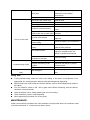
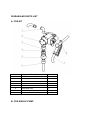
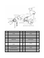
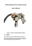
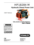
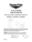
DC/AC Standard Fuel Transfer Pumps User’s Manual Sku No. 1031938 WARNING Read carefully and understand all INSTRUCTIONS before operating. Failure to follow the safety rules and other basic safety precautions may result in serious personal injury. Save these instructions in a safe place and on hand so that they can be read when required. SAFETY INSTRUCTIONS To ensure safe and efficient operation, it is essential to read and follow each of these warnings and precautions. 1. DO NOT smoke near pump or use pump near an open flame. Fire could result. 2. Disconnect power to pump before servicing pump. 3. Turn off the switch before connecting power. 4. Take motors needing service to an authorized repair shop or return to factory to maintain. 5. A filter should be used on pump outlet to ensure that no foreign material is transferred to fuel tank. 6. Tank or barrel should be anchored to prevent tipping in both the full and empty conditions. WARNING 1. Electrical wiring should be done a licensed electrician in compliance with local codes. Rigid conduit should be used and proper ground must be provided to avoid the possibility of electrical shock. Failure to comply with this warning could result in serious injury and/or loss of property. 2. This product should not be used for fluid transfer into aircraft. This product is not suited for use with fluids for human consumption or fluids containing water. 3. Extreme operating conditions with working cycles longer than 30 minutes can cause the motor temperature to rise, thus damaging the motor itself. Each 30-minute working cycle should always be followed by a 30-minute power-off cooling phase. GENERAL DESCRIPTION These products are positive displacement, rotary vane pumps. Depending on installation and viscosity, these pumps can deliver up to 8GPM or 30LPM. Their rugged design makes for a long life of dependability. TECHNICAL INFORMATION ¾ ¾ ¾ ¾ Inlet: 2” male on tank adapter, 3/4” female on pump Outlet: 3/4” female for 8GPM/30LPM Built-in bypass valve. Furnished with: 13ft/4m delivery hose 1pc steel suction pipe 1pc Aluminum manual nozzle. 2” Quick change coupling ¾ Electrical Specification ELECTRICAL POWER CURRENT PUMP MODEL 1031938 Current Voltage Maximum (Amp) DC 12 25 Flow Rate (L/min /GPM) 30/8 OPERATING CONDITIONS Temperature: min -20°C / max +60°C Relative Humidity: max 90% FLUID COMPATIBILITY These products are compatible with the following fluids: Diesel, Kerosene, Mineral Spirits Do NOT use with other fluids without consulting manufacturer. INSTALLATION INSTRUCTIONS 1. 2. 3. 4. 5. 6. 7. 8. Tightly screw suction pipe into inlet coupling of pumping unit. Extend suction pipe into truck tank or barrel to within 3” of tank bottom. Screw inlet coupling of pump into 2” tank or barrel opening. Inlet coupling must be completely and securely threaded into an undamaged tank or barrel bung. During installation and maintenance, make sure that the electric supply lines are not live. Always turn off the switch before supplying electrical power. Check the correct rotation direction of the DC pump. If it is inverted, check the polarity of the connection cable. a) RED cable: positive pole (+) b) BLACK cable: negative pole (-) Systems should be designed to require a minimum amount of suction lift. Maximum “equivalent feet of lift” is 8’ for diesel fuel. Tank or barrel must be properly vented. A water separator should be used for pumping diesel fuel. Power to the unit should be supplied from a dedicated 30 amp circuit breaker. No other equipment should be powered from this breaker. If two pumps are supplied from one breaker, that breaker must be capable of handing the load of both motors. PROBLEMS AND SOLUTIONS Problem Possible Cause Lack of electric power Corrective Action Check the electrical connections and the safety systems Rotor jams Check for possible damage or obstruction of the rotating components. Motor problems Contact with the service department Low level in the suction tank Refill the tank Foot valve blocked Clean and/or replace the valve Filter clogged Clean the filter Excessive suction pressure Lower the pump with respect to the Level High loss of head in the circuit Use shorter tubing or of greater (working with the by-pass open) Diameter Low or no flow rate By-pass valve blocked Dismantle the valve, clean and/or replace it Air entering the pump or the suction tubing Check the seals of the connections A narrowing in the suction Tubing Use tubing suitable for working under suction pressure Low rotation speed Check the voltage at the pump. Adjust the voltage and/or use cables of greater cross-section The suction tubing is resting on Raise the tubing the bottom of the tank Increased pump noise Leakage from the pump body Cavitations occurring Reduce suction pressure Irregular functioning of the by-pass Dispense until the air is purged from the circuit Air present in the diesel fuel Verify the suction connections Seal damaged Check and replace the mechanical seal Daily Use If using flexible tubing, attach the ends of the tubing to the tanks. In the absence of an appropriate slot, solidly grasp the delivery tube before beginning dispensing. Before starting the pump make sure that the delivery valve is closed (dispensing nozzle or line valve). Turn the ON/OFF switch to ON. The by-pass valve allows functioning with the delivery closed for only brief periods. Open the delivery valve, solidly grasping the end of the tubing. Close the delivery valve to stop dispensing. When dispensing is finished, turn off the pump. MAINTENANCE Under normal working conditions the noise emission from all models does not exceed the value of 80 db at a distance of 1 meter from the electric pump. DIGRAM AND PARTS LIST A. FOR KIT Part No Component Description Quantity 1 90° Elbow 1 2 Fuel pump 1 3 Nut 1 4 Adapter 1 5 Tank Adapter 1 6 Extensible Pipe 1 7 4m Delivery hose 1 8 Manual nozzle 1 B. FOR SINGLE PUMP No. Description Qty. No. Description Qty. 1 Front cover 1 17 Washer 1 2 O-ring 1 18 O-ring 1 3 Blade 5 19 Seal 1 4 Rotor 1 20 Fork for turning switch 1 5 Pump chamber 1 21 Switch 1 6 Seals 1 22 Bolt 2 7 Spring collar 1 23 Switch bracket 1 8 Hex bolt 1 24 Hexagon flange bolts 11 9 Electric Motor 1 25 Junction box 1 10 DC Power cable with Fuse carrier 1 26 O-ring 1 11 Fuse 1 27 Valve 1 12 Cable clip 1 28 Spring 1 13 Junction box cover 1 29 O-ring 1 14 Nozzle holder 1 30 Sealed screw 1 15 nylon self-locking screw 1 16 Switch connector 1