1
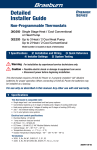
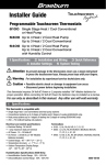
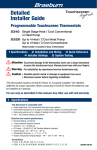
Mitsubishi Industrial Robot / MELFA RV-2SDB/RV-2SQB Series
Product Configuration
RV-2SDB
RV-2SQB
MR-J3
MITSUBISHI INDUSTRIAL ROBOT
<Must be prepared by the customer>
Ethernet
Robot arm
RV-2SD
Robot arm
RV-2SQ
SSCNET III
(Optical
communications)
iQ Platform-compliant
programmable controller
RV-2SDB/RV-2SQB Series
Vision system
GOT
GOT
Additional axis function
Robot CPU (RCPU)
Additional axis function
USB communications
<Optional>
<Optional>
CR1DA-771
Encoder input function
Pulse encoder
Standard High-functionality
version
version
Teaching pendant
Equipped with various
interfaces as standard
<Must be prepared
by the customer>
Standard High-functionality
version
version
Teaching pendant
MR-J3
Drive unit
(DU1A)
<Must be prepared
by the customer>
Configurations Options
Classification
Name
Solenoid valve set
Robot arm
Hand output cable
Hand input cable
Hand curl tube
Stopper for changing motion space
Machine cable, for extension/fixed
Controller
Machine cable, for extension/flexible
Teaching pendant, standard version
High-function teaching pendant
Air hand interface
Parallel I/O unit
External I/O cable
Parallel I/O interface
External I/O cable
CC-Link interface
PROFIBUS interface
DeviceNet Slave interface
Additional memory
Perssonal computer support softwware
Perssonal computer support softwware-mini
Personal computer cable
MELFA-Vision
3D simulator (MELFA-Works)
Service part Backup battery
Type
1E-VD01/VD01E
1E-VD02/VD02E
1E-GR35S
1S-HC30C-11
1E-ST0402C
1E-ST0404C
1S-DH-11J1
1S-DH-11J2
1S-DH-11J3
1S-10CBL-03
1S-15CBL-03
1S-10LCBL-03
1S-15LCBL-03
R32TB
R56TB
2A-RZ365/375
2A-RZ361/371
2A-CBL05/2A-CBL15
2D-TZ368/378
2D-CBL05/2D-CBL15
2D-TZ576
2A-RZ577
2D-TZ571
2D-TZ454
3D-11C-WINJ
3D-12C-WINJ
2D-232CBL03M
3D-51C-WINJ
3D-21C-WINJ
ER6
Q6BAT
Specification overview
Solenoid valve (with an output cable, 1 valve) (sink/source)
Solenoid valve (with an output cable, 2 valves) (sink/source)
With a robot-side connector, not terminated at another end
With a robot-side connector, not terminated at another end
4 tube, number of sets - 2
4 tube, number of sets - 4
For effecting change to J1 axis mechanism (±210 deg., ±150 deg., ±90 deg.)
For effecting change to J2 axis mechanism (±30 deg.)
For effecting change to J3 axis mechanism (+70 deg.)
Replacement type: 10m
Replacement type: 15m
Replacement type: 10m
Replacement type: 15m
7m: Standard / 15m: Custom
7m: Standard / 15m: Custom
8 output points, used exclusively for hand (sink/source)
32 output points / 32 input points (sink/source)
Cable length: 5m / 15m, not terminated at one end (for 2A-RZ361/371)
32 output points / 32 input points (sink/source)
Cable length: 5m / 15m, not terminated at one end (for 2D-TZ368/378)
CC-Link intelligent device station, Version 2.0, 1 to 4 stations
Slave station, combined total number of input and output data: 192 words
Slave station, Release 2.0 is supported
User program area with additional memory: 2MB
With simulation function (CD-ROM)
Simple version (CD-ROM)
For PC-AT compatible machine, 3m
COGNEX Vision System-compliant
Add-in to Solidworks software
Installed in the robot arm (Quantity: 4pcs)
Installed in the controller (Quantity: 1pc)
RV-2SDB
RV-2SQB
RV-2SDB / RV-2SQB
RV-2SDB/RV-2SQB
HEAD OFFICE: TOKYO BUILDING, 2-7-3, MARUNOUCHI, CHIYODA-KU, TOKYO 100-8310, JAPAN
http://Global.MitsubishiElectric.com/
L(NA)-09044ENG 1003(MEE)
This brochure has been issued in Mar. 2010. The contents of this brochure are subject to change
for improvements without notice. Contact with Mitsubishi when referring to this brochure.
Date of issue:Mar. 2010
MELFA RV-2SDB/RV-2SQB Series Coming Along!! A Slim, High-speed, High-functionality Robot with a 2-kg Carrying Capacity
[Robot's Outer Dimensions and Motion Space]
-240
504
70
4
75
5
31.
View A
50
100
Arm design that allows for coordination
with the peripheral apparatuses
• Flap arm construction further cuts back robot's minimum operating
radius, securing a necessary motion space.
• Reduced protrusion of the elbow arm lessens possible interference in
the rear space.
• The wrist section which is made less bulky provides easy access
through a narrow opening.
Our assembly operation requires robot to take
different posture from one step to another...
Axes at the end of the robot arm (J4
through J6) move at a high speed.
The robot's ability to handle
work near at hand permits
a compact layout.
We have had to allow some of the space
adjacent to the robot to be wasted...
The upper (No. 1) arm (between J2 and J3
axes) employs a flap (collapsible) construction.
The arm is of flap
construction.
A large variety of interfaces are offered
to assure a high degree of scalability
• The robot comes standard with additional axis control interface,
Ethernet interface, and encoder interface (for tracking purpose,
available with SD Series only). This makes it easy to build a
manufacturing system with robot placed at its heart.
• Input/output to and from the robot can be controlled directly from GOT
without the intermediary of a sequencer. A simplified operating panel
can be created without using ladder programs. (This feature is available
with SD Series only.)
A rich new selection of software programs
that guide users through their startup phases
• RT ToolBox2 : A computer software containing varied features
essential for startup such as program editing, debugging
and cycle time planning (optional).
• MELFA-Vision: Software designed to employ vision system for
maximum ease of use (optional).
• MELFA-Works: A 3D robot simulator that provides powerful support for
system design and preliminary study (optional).
The robot can cover a larger
operating area with its arm
oriented as it is.
Robot has an omnidirectional
(360-degree) reach.
Even with a ceiling-hung unit used
with a compactly-built assembly cell...
We want to set up a work position in four
directions to render our system compact...
The shoulder (J2 axis) is provided with
an extended motion space.
Unlike its
conventional
varieties, the robot
can even extend
back into its rear
space.
700mm
Robot's
forward
direction
The waist (J1 axis) is provided with
a motion space beyond 360 .
Apparatus 1 Apparatus 2
Delivery
Apparatus 3
Cycle time has been reduced by
increasing the speed of axes J4, J5,
and J6 up about 10% from our
high-end model (RB-3SDB).
Layout is made Position/posture at minimum
operating radius
more compact.
The arm of flap construction further cuts
back on minimum operating radius!!
R139.5mm
Also, a broad motion space (maximum
radius - minimum radius) is insured
despite of reduced operating radius!!
About 360mm
A compact layout can be obtained
by making the most of the motion
space thus secured.
(Installation
reference surface)
94
Specification
Robot Arm
Item
Type
Protection class
Unit
Installation
Structure
Degrees of freedom
Arm length
Maximum reach radius
J1
J2
J3
Operating
J4
range
J5
J6
J1
J2
J3
Maximum
J4
speed
J5
J6
Maximum composite speed
Cycle time
Mass load Rated
capacity Maximum
Position repeatability
Mass
mm
mm
deg
deg/s
mm/s
kg
kg
mm
kg
Specification
RV-2SDB / RV-2SQB
IP30
Floorstanding, ceiling-hung,
and wall-mounted *1
Vertical articulated arm robot
6
230+270
504
480 (-240 to +240)
240 (-120 to +120)
160 (0 to +160)
400 (-200 to +200)
240 (-120 to +120)
720 (-360 to +360)
225
150
275
412
450
720
4400
On the order of 0.6 sec.
2.0
3.0 (wrist, downward)
±0.02
19
380mm
380mm
Removal
CL
The motion space of the shoulder (J2
axis) is extended on the minus side so that
it can be rotated into a space in the
backward direction. An ample work area is
insured in a ceiling-hung installation, too.
A larger operating area obtained
without the need to change the
orientation of the robot means that
needless motion will be lessened
and cycle time will be shortened.
Examples of
moving paths
The motion space for the wais (J1
axis) is broadened to 480 (±240 ) so
that it can rotate 360 and more (360
+ ).
Shortest motion distance cuts back
on cycle time and raises degree of
freedom in robot arrangement.
(40)
4- 9
instration hole
82
(135)
67.5 67.5
(120)
295
Wrist's downward
singularity boundary
280
(160)
View B
Rear view/details of installation dimensions
Side View
B
Top view
Work
Analyses indicate that making the
arm change its posture faster is
effective at achieving speedup of
assembly operation. Therefore,
provision is made to let axes at the
end of the robot arm (J4, J5, and J6)
move at a greater speed!!
0
+24
CR1QA-771
*1 There are limits to the motion space of J1.
*2 All axes are equipped with a brake.
Close proximity
is permitted!!
Assembly cell
389
40
RV-2SDB/RV-2SQB
(135)
Rz 25
R1
CR1DA-771
82
67.5 67.5
(Installation
reference surface)
R504
Robot Arm
The robot can quickly change its
posture in response to needs frequently
arising during assembly operation.
799
623
• Maximum combined speed is 4,400 mm/sec. Furthermore, the speed at
which the wrist section (secondary arm) moves is boosted to cut down
on cycle time in assembly operation.
• A positioning repeatability of as high as ±0.02 mm is realized. Highrigidity arm and active-gain control are combined to achieve a high
straight-ahead motion accuracy.
230
185
Advanced servo control backs up a high-speed
high-accuracy operation
0
R140
Reduced in profile yet has a large operating radius
• The length and shape of the arm are designed for optimum performance
with a maximum reach being further extended yet the ability retained to
cover work area near to the unit.
• A greater operating radius is insured in applications calling for a ceilinghung unit, as well.
• The robot has an enlarged swing area (-240 to +240 ), enabling the rear
space to be put to good use, too.
0
+12
-12
Motion space
at Point P
20H7, dept
h6
40h
8, d
epth
6
Detail of mechanical interface section
504
A
Point P
4-M5 screw, depth 8
504
270
160
R50
Features
5H7, depth 8
45
Wrist's downward limit
Motion space at Point P
(160)
Motion space at Point P
Rz 25
A compactly-built, vertical multi-axis articulated
arm robot ideally suited for future-oriented
assembly cells manufacturing a wide variety of
products, each in varying quantities.
Controller
Item
Type designation
Robot language
Position teaching method
Unit
Specification
CR1DA-771 (RV-2SDB)
CR1QA-771 (RV-2SQB)
MELFA-BASIC V
Teaching method, MDI method
0 input / 0 output
8192 / 8192
Input/output
Point
(maximum 256/256, available as option)
(between sequencer and robot)
Dedicated input/output
Point
Assigned according to general-purpose I/O.
Input for shutdown purpose only Point
1
External Hand open/close input/output
Point
4 inputs / 0 output
External emergency shutdown input Point
input/
1
Door switch input
output
Point
1
1
Enabling device input
Point
1
Synchronization of additional axes Point
1
Mode output
Point
1
Error output
Point
RS-232
ports
1
1
RS-422
ports
Ethernet
ports
1 (dual-use, user and TB)
1
USB
ports
1
Interface
1
Additional-axis I/F
channels
Tracking I/F
channels
1
1
Slot for hand
slots
Extension slot
slots
1
Single phase, AC200 to 230±10% (180 to 253)
Input voltage range
V
Power
0.5
Power capacity
KVA
supply
50 / 60
Frequency
Hz
240(W) x 290(D) x 200(H)
External dimensions
mm
Approx. 9
Weight
kg
Self-contained floor type / open structure (IP20)
Structure
Type designation
CPU
Q172DRCPU
Remark
4 additional outputs are available as option.
Double-redundant
Double-redundant
Double-redundant
Double-redundant
Double-redundant
Double-redundant
Extensions for computer, vision sensor, etc.
I/F dedicated to TB
10BASE-T / 100BASE-TX
Device function only, mini-B terminal
SSCNET III
For connecting encoder cable
Slot dedicated to air hand I/F
For installing optional I/F
Not including in-rush current
Protrusions excluded
iQ Platform-compliant
SQ Series Controller - New Capabilities
iQ Platform-Compliant High-Speed Communications
Robot CPU mounted on the basis of an iQ Platform-compliant
sequencer enables data communications between the
sequencer which controls and the robot which is controlled
to occur much faster and in much greater volumes.
Input/output to and from external apparatuses can be controlled
by each sequencer. This leads to a neat, clutter-free cabling.
Easily legible, information-rich robot status indication
The operational status of the robot is expanded on the
sequencer-side memory without the intervention of software
programs. Connection of GOT enables the robot's current data
values, error description, etc. to be indicated on-screen. The
result is a vividly-expressed, human-friendly display system.
Robot can be readily operated under the control
of sequencer language alone.
You do not have to get acquainted with robot language!
MELFA Series RV-2SDB/2SQB comes provided with features
which let the sequencer control the robot as if it were a single
piece of actuator, thus doing away with the intervention of
robot language.
Sequencer language is all that is needed to control the robot
as it performs varied tasks including pick-and-place and
aligning of workpieces.
(MELFA Series can run just as well on ordinary robot
language, too.)
Robot can be readily operated under the
control of sequencer language alone!!
We wonder if time it
takes for us to get
acquainted with robot
language wouldn't
justify ...
Programming can be
accomplished by the
sequencer language you
are accustomed
to use.
No robot
programs are
needed.
Operation commands
Hand
are issued to the robot
in sequencer
language.
Conveyor
Work
MELFA Series RV-S2SDB/2SQB come with features capable
of implementing robot control directly from a sequencer.
You can save on the time required to get
acquainted with robot language!!
Your robot system can be started simply and
quickly by a sequencer language.
Setting of robot's internal data can be
easily achieved and displayed on GOT.
It would be nice if we can
keep track of robot
information together with
all other associated
information on a single
system operation console.
Various essential data
and information on the
robot are displayed on
GOT without the
intervention of robot
programs.
GOT display panels
Sample graphics data
• Robot operation window
• Current values display window
• Maintenance forecast window
• User Manual window
• Error indication
GOT1000
Various data is stored in a memory shared by
sequencer multi-CPUs.
Sample graphics data can be downloaded from
MELFANSWeb website.
Mitsubishi Industrial Robot / MELFA RV-2SDB/RV-2SQB Series
Product Configuration
RV-2SDB
RV-2SQB
MR-J3
MITSUBISHI INDUSTRIAL ROBOT
<Must be prepared by the customer>
Ethernet
Robot arm
RV-2SD
Robot arm
RV-2SQ
SSCNET III
(Optical
communications)
iQ Platform-compliant
programmable controller
RV-2SDB/RV-2SQB Series
Vision system
GOT
GOT
Additional axis function
Robot CPU (RCPU)
Additional axis function
USB communications
<Optional>
<Optional>
CR1DA-771
Encoder input function
Pulse encoder
Standard High-functionality
version
version
Teaching pendant
Equipped with various
interfaces as standard
<Must be prepared
by the customer>
Standard High-functionality
version
version
Teaching pendant
MR-J3
Drive unit
(DU1A)
<Must be prepared
by the customer>
Configurations Options
Classification
Name
Solenoid valve set
Robot arm
Hand output cable
Hand input cable
Hand curl tube
Stopper for changing motion space
Machine cable, for extension/fixed
Controller
Machine cable, for extension/flexible
Teaching pendant, standard version
High-function teaching pendant
Air hand interface
Parallel I/O unit
External I/O cable
Parallel I/O interface
External I/O cable
CC-Link interface
PROFIBUS interface
DeviceNet Slave interface
Additional memory
Perssonal computer support softwware
Perssonal computer support softwware-mini
Personal computer cable
MELFA-Vision
3D simulator (MELFA-Works)
Service part Backup battery
Type
1E-VD01/VD01E
1E-VD02/VD02E
1E-GR35S
1S-HC30C-11
1E-ST0402C
1E-ST0404C
1S-DH-11J1
1S-DH-11J2
1S-DH-11J3
1S-10CBL-03
1S-15CBL-03
1S-10LCBL-03
1S-15LCBL-03
R32TB
R56TB
2A-RZ365/375
2A-RZ361/371
2A-CBL05/2A-CBL15
2D-TZ368/378
2D-CBL05/2D-CBL15
2D-TZ576
2A-RZ577
2D-TZ571
2D-TZ454
3D-11C-WINJ
3D-12C-WINJ
2D-232CBL03M
3D-51C-WINJ
3D-21C-WINJ
ER6
Q6BAT
Specification overview
Solenoid valve (with an output cable, 1 valve) (sink/source)
Solenoid valve (with an output cable, 2 valves) (sink/source)
With a robot-side connector, not terminated at another end
With a robot-side connector, not terminated at another end
4 tube, number of sets - 2
4 tube, number of sets - 4
For effecting change to J1 axis mechanism (±210 deg., ±150 deg., ±90 deg.)
For effecting change to J2 axis mechanism (±30 deg.)
For effecting change to J3 axis mechanism (+70 deg.)
Replacement type: 10m
Replacement type: 15m
Replacement type: 10m
Replacement type: 15m
7m: Standard / 15m: Custom
7m: Standard / 15m: Custom
8 output points, used exclusively for hand (sink/source)
32 output points / 32 input points (sink/source)
Cable length: 5m / 15m, not terminated at one end (for 2A-RZ361/371)
32 output points / 32 input points (sink/source)
Cable length: 5m / 15m, not terminated at one end (for 2D-TZ368/378)
CC-Link intelligent device station, Version 2.0, 1 to 4 stations
Slave station, combined total number of input and output data: 192 words
Slave station, Release 2.0 is supported
User program area with additional memory: 2MB
With simulation function (CD-ROM)
Simple version (CD-ROM)
For PC-AT compatible machine, 3m
COGNEX Vision System-compliant
Add-in to Solidworks software
Installed in the robot arm (Quantity: 4pcs)
Installed in the controller (Quantity: 1pc)
RV-2SDB
RV-2SQB
RV-2SDB / RV-2SQB
RV-2SDB/RV-2SQB
HEAD OFFICE: TOKYO BUILDING, 2-7-3, MARUNOUCHI, CHIYODA-KU, TOKYO 100-8310, JAPAN
http://Global.MitsubishiElectric.com/
L(NA)-09044ENG 1003(MEE)
This brochure has been issued in Mar. 2010. The contents of this brochure are subject to change
for improvements without notice. Contact with Mitsubishi when referring to this brochure.
Date of issue:Mar. 2010